Power Integrations 5245 Hellyer Avenue, San Jose, CA 95138 USA. Tel: +1 408 414 9200 Fax: +1 408 414 9201 www.power.com Title Reference Design Report for a 150 W Power Factor Corrected LLC Power Supply Using HiperPFS TM -2 (PFS7326H) and HiperLCS TM (LCS702HG) Specification 90 VAC – 265 VAC Input; 150 W (~43 V at 0 - 3.5 A) Output (Constant Current) Application LED Streetlight Author Applications Engineering Department Document Number RDR-382 Date June 28, 2017 Revision 6.5 Summary and Features Integrated PFC and LLC stages for a very low component count design Continuous mode PFC using low cost ferrite core High frequency (250 kHz) LLC for extremely small transformer size. >95% full load PFC efficiency at 115 VAC >95% full load LLC efficiency System efficiency 91% / 93% at 115 VAC / 230 VAC Start-up circuit eliminates the need for a separate bias supply On-board current regulation and analog dimming PATENT INFORMATION The products and applications illustrated herein (including transformer construction and circuits external to the products) may be covered by one or more U.S. and foreign patents, or potentially by pending U.S. and foreign patent applications assigned to Power Integrations. A complete list of Power Integrations' patents may be found at www.powerint.com. Power Integrations grants its customers a license under certain patent rights as set forth at <http://www.powerint.com/ip.htm>.
Transcript
Power Integrations 5245 Hellyer Avenue, San Jose, CA 95138 USA. Tel: +1 408 414 9200 Fax: +1 408 414 9201
www.power.com
Title
Reference Design Report for a 150 W Power Factor Corrected LLC Power Supply Using HiperPFS TM -2 (PFS7326H) and HiperLCSTM (LCS702HG)
Specification 90 VAC – 265 VAC Input; 150 W (~43 V at 0 - 3.5 A) Output (Constant Current)
Application LED Streetlight
Author Applications Engineering Department
Document Number RDR-382
Date June 28, 2017
Revision 6.5
Summary and Features Integrated PFC and LLC stages for a very low component count design Continuous mode PFC using low cost ferrite core High frequency (250 kHz) LLC for extremely small transformer size. >95% full load PFC efficiency at 115 VAC >95% full load LLC efficiency
System efficiency 91% / 93% at 115 VAC / 230 VAC Start-up circuit eliminates the need for a separate bias supply On-board current regulation and analog dimming
PATENT INFORMATION The products and applications illustrated herein (including transformer construction and circuits external to the products) may be covered by one or more U.S. and foreign patents, or potentially by pending U.S. and foreign patent applications assigned to Power Integrations. A complete list of Power Integrations' patents may be found at www.powerint.com. Power Integrations grants its customers a license under certain patent rights as set forth at <http://www.powerint.com/ip.htm>.
RDR-382, 150 W Street Light Power Supply 28-Jun-17
Page 2 of 82
Power Integrations, Inc. Tel: +1 408 414 9200 Fax: +1 408 414 9201 www.power.com
5 PCB Layout ...................................................................................................... 15 6 Bill of Materials ................................................................................................ 17 7 LED Panel Characterization ............................................................................... 20
7.1 LED Panel Current Sharing ......................................................................... 21 7.2 Constant Voltage Load ............................................................................... 22
12 RD-382 Performance Data ............................................................................. 53 12.1 LLC Stage Efficiency ................................................................................... 53 12.2 Total Efficiency .......................................................................................... 54 12.3 Power Factor ............................................................................................. 55 12.4 Harmonic Distribution ................................................................................ 56 12.5 THD, 100% Load ....................................................................................... 56 12.6 Output Current vs. Dimming Input Voltage .................................................. 57
13 Waveforms ................................................................................................... 58 13.1 Input Current, 100% Load .......................................................................... 58 13.2 LLC Primary Voltage and Current ................................................................ 59 13.3 Output Rectifier Peak Reverse Voltage ......................................................... 60 13.4 PFC Inductor + Switch Voltage and Current, 100% Load .............................. 61 13.5 AC Input Current and PFC Output Voltage during Start-up ............................ 62 13.6 LLC Start-up Output Voltage and Transformer Primary Current Using LED Output Load 62 13.7 Output Voltage / Current Start-up Using LED Load ....................................... 63 13.8 LLC Output Short-Circuit ............................................................................. 64 13.9 Output Ripple Measurements ...................................................................... 65
17.1 Line Surge Test Set-up ............................................................................... 79 17.2 Differential Mode Surge, 1.2 / 50 sec ......................................................... 80 17.3 Common Mode Surge, 1.2 / 50 sec ............................................................ 80
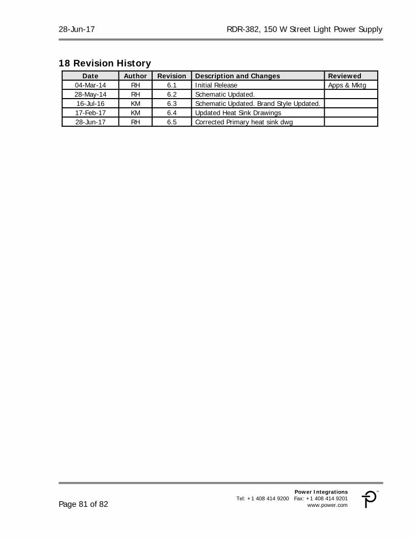
18 Revision History ............................................................................................ 81
RDR-382, 150 W Street Light Power Supply 28-Jun-17
Page 4 of 82
Power Integrations, Inc. Tel: +1 408 414 9200 Fax: +1 408 414 9201 www.power.com
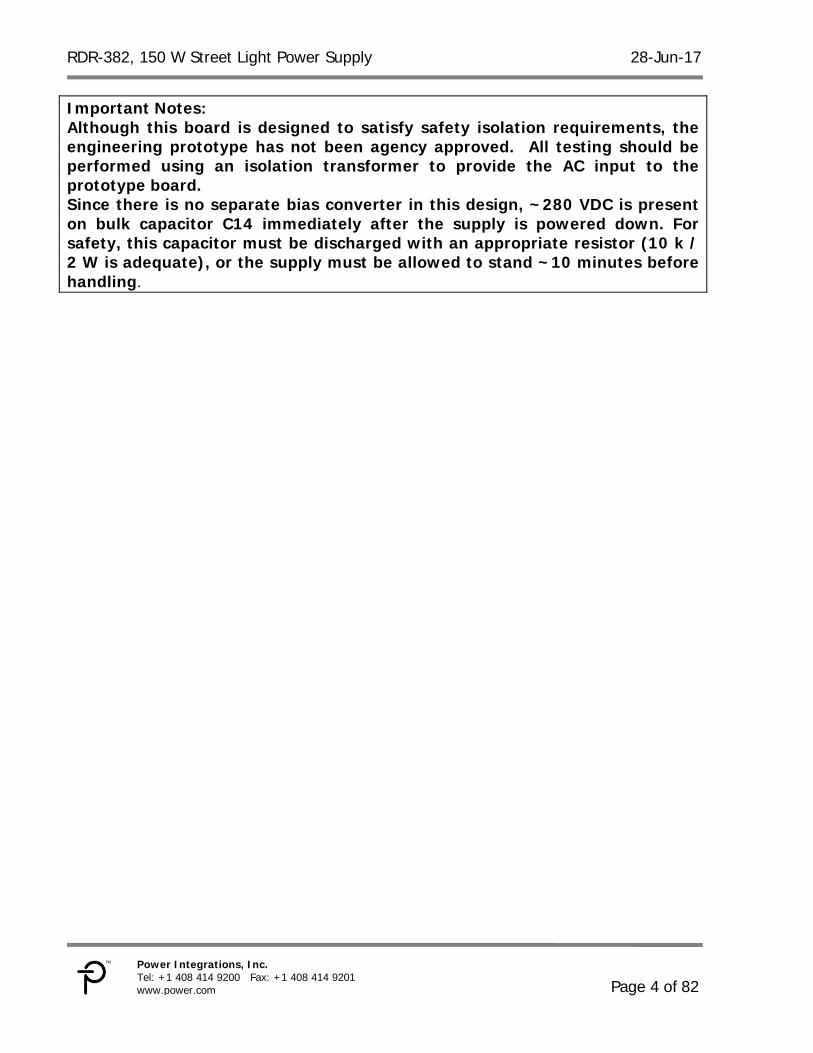
Important Notes: Although this board is designed to satisfy safety isolation requirements, the engineering prototype has not been agency approved. All testing should be performed using an isolation transformer to provide the AC input to the prototype board. Since there is no separate bias converter in this design, ~280 VDC is present on bulk capacitor C14 immediately after the supply is powered down. For safety, this capacitor must be discharged with an appropriate resistor (10 k / 2 W is adequate), or the supply must be allowed to stand ~10 minutes before handling.
28-Jun-17 RDR-382, 150 W Street Light Power Supply
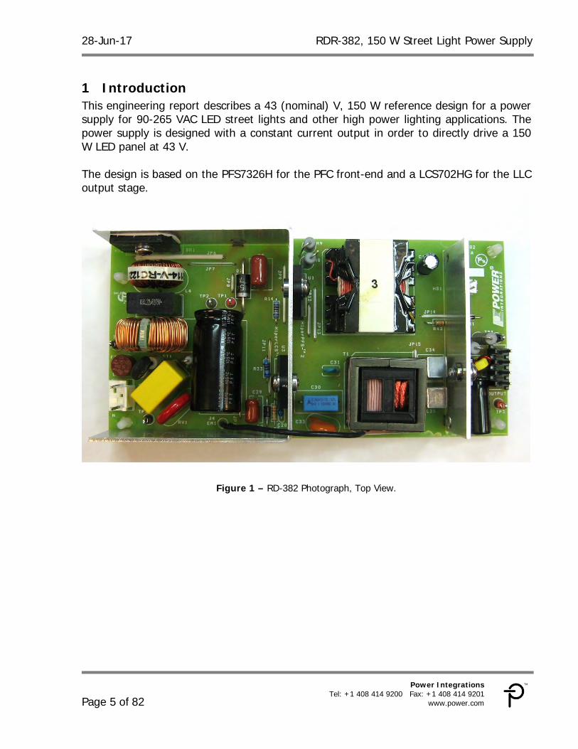
1 Introduction This engineering report describes a 43 (nominal) V, 150 W reference design for a power supply for 90-265 VAC LED street lights and other high power lighting applications. The power supply is designed with a constant current output in order to directly drive a 150 W LED panel at 43 V. The design is based on the PFS7326H for the PFC front-end and a LCS702HG for the LLC output stage.
Figure 1 – RD-382 Photograph, Top View.
RDR-382, 150 W Street Light Power Supply 28-Jun-17
Page 6 of 82
Power Integrations, Inc. Tel: +1 408 414 9200 Fax: +1 408 414 9201 www.power.com
Figure 2 – RD-382 Photograph, Bottom View.
28-Jun-17 RDR-382, 150 W Street Light Power Supply
2 Power Supply Specification The table below represents the minimum acceptable performance for the design. Actual performance is listed in the results section.
Description Symbol Min Typ Max Units Comment Input Voltage VIN 90 265 VAC 3 Wire input.
Frequency fLINE 47 50/60 64 Hz
Power Factor PF 0.97 Full load, 230 VAC
Main Converter Output
Output Voltage VLG 43 V 43 VDC (nominal - defined by LED load)
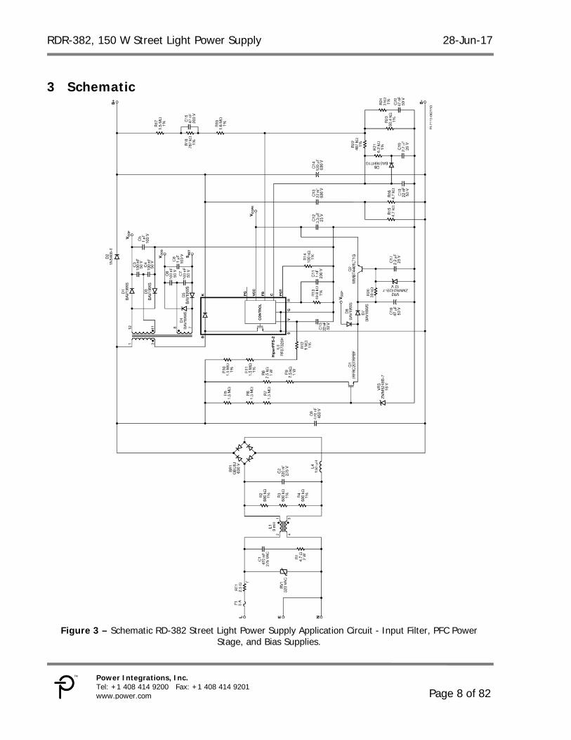
Figure 4 – Schematic of RD-382 Street light Power Supply Application Circuit, LLC Stage.
RDR-382, 150 W Street Light Power Supply 28-Jun-17
Page 10 of 82
Power Integrations, Inc. Tel: +1 408 414 9200 Fax: +1 408 414 9201 www.power.com
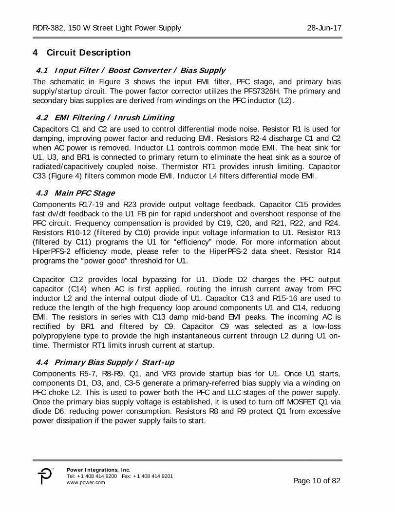
4 Circuit Description
4.1 Input Filter / Boost Converter / Bias Supply The schematic in Figure 3 shows the input EMI filter, PFC stage, and primary bias supply/startup circuit. The power factor corrector utilizes the PFS7326H. The primary and secondary bias supplies are derived from windings on the PFC inductor (L2).
4.2 EMI Filtering / Inrush Limiting Capacitors C1 and C2 are used to control differential mode noise. Resistor R1 is used for damping, improving power factor and reducing EMI. Resistors R2-4 discharge C1 and C2 when AC power is removed. Inductor L1 controls common mode EMI. The heat sink for U1, U3, and BR1 is connected to primary return to eliminate the heat sink as a source of radiated/capacitively coupled noise. Thermistor RT1 provides inrush limiting. Capacitor C33 (Figure 4) filters common mode EMI. Inductor L4 filters differential mode EMI.
4.3 Main PFC Stage Components R17-19 and R23 provide output voltage feedback. Capacitor C15 provides fast dv/dt feedback to the U1 FB pin for rapid undershoot and overshoot response of the PFC circuit. Frequency compensation is provided by C19, C20, and R21, R22, and R24. Resistors R10-12 (filtered by C10) provide input voltage information to U1. Resistor R13 (filtered by C11) programs the U1 for “efficiency” mode. For more information about HiperPFS-2 efficiency mode, please refer to the HiperPFS-2 data sheet. Resistor R14 programs the “power good” threshold for U1. Capacitor C12 provides local bypassing for U1. Diode D2 charges the PFC output capacitor (C14) when AC is first applied, routing the inrush current away from PFC inductor L2 and the internal output diode of U1. Capacitor C13 and R15-16 are used to reduce the length of the high frequency loop around components U1 and C14, reducing EMI. The resistors in series with C13 damp mid-band EMI peaks. The incoming AC is rectified by BR1 and filtered by C9. Capacitor C9 was selected as a low-loss polypropylene type to provide the high instantaneous current through L2 during U1 on-time. Thermistor RT1 limits inrush current at startup.
4.4 Primary Bias Supply / Start-up Components R5-7, R8-R9, Q1, and VR3 provide startup bias for U1. Once U1 starts, components D1, D3, and, C3-5 generate a primary-referred bias supply via a winding on PFC choke L2. This is used to power both the PFC and LLC stages of the power supply. Once the primary bias supply voltage is established, it is used to turn off MOSFET Q1 via diode D6, reducing power consumption. Resistors R8 and R9 protect Q1 from excessive power dissipation if the power supply fails to start.
28-Jun-17 RDR-382, 150 W Street Light Power Supply
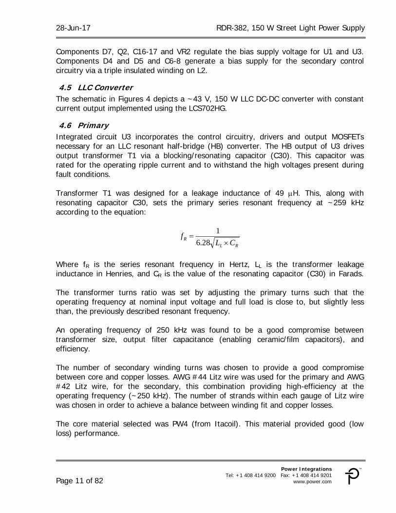
Components D7, Q2, C16-17 and VR2 regulate the bias supply voltage for U1 and U3. Components D4 and D5 and C6-8 generate a bias supply for the secondary control circuitry via a triple insulated winding on L2.
4.5 LLC Converter The schematic in Figures 4 depicts a ~43 V, 150 W LLC DC-DC converter with constant current output implemented using the LCS702HG.
4.6 Primary Integrated circuit U3 incorporates the control circuitry, drivers and output MOSFETs necessary for an LLC resonant half-bridge (HB) converter. The HB output of U3 drives output transformer T1 via a blocking/resonating capacitor (C30). This capacitor was rated for the operating ripple current and to withstand the high voltages present during fault conditions. Transformer T1 was designed for a leakage inductance of 49 H. This, along with resonating capacitor C30, sets the primary series resonant frequency at ~259 kHz according to the equation:
RL
RCL
f
28.6
1
Where fR is the series resonant frequency in Hertz, LL is the transformer leakage inductance in Henries, and CR is the value of the resonating capacitor (C30) in Farads. The transformer turns ratio was set by adjusting the primary turns such that the operating frequency at nominal input voltage and full load is close to, but slightly less than, the previously described resonant frequency. An operating frequency of 250 kHz was found to be a good compromise between transformer size, output filter capacitance (enabling ceramic/film capacitors), and efficiency. The number of secondary winding turns was chosen to provide a good compromise between core and copper losses. AWG #44 Litz wire was used for the primary and AWG #42 Litz wire, for the secondary, this combination providing high-efficiency at the operating frequency (~250 kHz). The number of strands within each gauge of Litz wire was chosen in order to achieve a balance between winding fit and copper losses. The core material selected was PW4 (from Itacoil). This material provided good (low loss) performance.
RDR-382, 150 W Street Light Power Supply 28-Jun-17
Page 12 of 82
Power Integrations, Inc. Tel: +1 408 414 9200 Fax: +1 408 414 9201 www.power.com
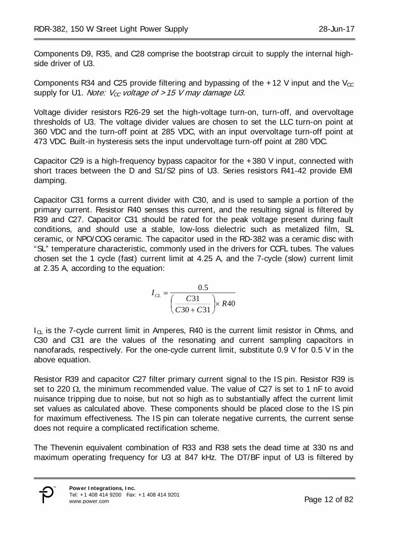
Components D9, R35, and C28 comprise the bootstrap circuit to supply the internal high- side driver of U3. Components R34 and C25 provide filtering and bypassing of the +12 V input and the VCC supply for U1. Note: VCC voltage of >15 V may damage U3. Voltage divider resistors R26-29 set the high-voltage turn-on, turn-off, and overvoltage thresholds of U3. The voltage divider values are chosen to set the LLC turn-on point at 360 VDC and the turn-off point at 285 VDC, with an input overvoltage turn-off point at 473 VDC. Built-in hysteresis sets the input undervoltage turn-off point at 280 VDC. Capacitor C29 is a high-frequency bypass capacitor for the +380 V input, connected with short traces between the D and S1/S2 pins of U3. Series resistors R41-42 provide EMI damping. Capacitor C31 forms a current divider with C30, and is used to sample a portion of the primary current. Resistor R40 senses this current, and the resulting signal is filtered by R39 and C27. Capacitor C31 should be rated for the peak voltage present during fault conditions, and should use a stable, low-loss dielectric such as metalized film, SL ceramic, or NPO/COG ceramic. The capacitor used in the RD-382 was a ceramic disc with “SL” temperature characteristic, commonly used in the drivers for CCFL tubes. The values chosen set the 1 cycle (fast) current limit at 4.25 A, and the 7-cycle (slow) current limit at 2.35 A, according to the equation:
403130
315.0
RCC
CICL
ICL is the 7-cycle current limit in Amperes, R40 is the current limit resistor in Ohms, and C30 and C31 are the values of the resonating and current sampling capacitors in nanofarads, respectively. For the one-cycle current limit, substitute 0.9 V for 0.5 V in the above equation. Resistor R39 and capacitor C27 filter primary current signal to the IS pin. Resistor R39 is set to 220 the minimum recommended value. The value of C27 is set to 1 nF to avoid nuisance tripping due to noise, but not so high as to substantially affect the current limit set values as calculated above. These components should be placed close to the IS pin for maximum effectiveness. The IS pin can tolerate negative currents, the current sense does not require a complicated rectification scheme. The Thevenin equivalent combination of R33 and R38 sets the dead time at 330 ns and maximum operating frequency for U3 at 847 kHz. The DT/BF input of U3 is filtered by
28-Jun-17 RDR-382, 150 W Street Light Power Supply
C23. The combination of R33 and R38 also selects burst mode “1” for U3. This sets the lower and upper burst threshold frequencies at 382 kHz and 437 kHz, respectively. The FEEDBACK pin has an approximate characteristic of 2.6 kHz per A into the FEEDBACK pin. As the current into the FEEDBACK pin increases so does the operating frequency of U3, reducing the output voltage. The series combination of R30 and R31 sets the minimum operating frequency for U3 at ~160 kHz. This value was set to be slightly lower than the frequency required for regulation at full load and minimum bulk capacitor voltage. Resistor R30 is bypassed by C21 to provide output soft start during start-up by initially allowing a higher current to flow into the FEEDBACK pin when the feedback loop is open. This causes the switching frequency to start high and then decrease until the output voltage reaches regulation. Resistor R31 is typically set at the same value as the parallel combination of R33 and R38 so that the initial frequency at soft-start is equal to the maximum switching frequency as set by R33 and R38. If the value of R31 is less than this, it will cause a delay before switching occurs when the input voltage is applied. Optocoupler U4 drives the U3 FEEDBACK pin through R32, which limits the maximum optocoupler current into the FEEDBACK pin. Capacitor C26 filters the FEEDBACK pin. Resistor R36 loads the optocoupler output to force it to run at a relatively high quiescent current, increasing its gain. Resistors R32 and R36 also improve large signal step response and burst mode output ripple. Diode D10 isolates R36 from the FMAX/soft start network.
4.7 Output Rectification The output of transformer T1 is rectified and filtered by D11 and C34-35. These capacitors have a polyester dielectric, chosen for output ripple current rating. Output rectifier D11 is a 150 V Schottky rectifier chosen for high efficiency. Intertwining the transformer secondary halves (see transformer construction details in section 8) reduces leakage inductance between the two secondary halves, reducing the worst-case peak inverse voltage and allowing use of a 150V Schottky diode with consequent higher efficiency. Additional output filtering is provided by L3 and C36. Capacitor C36 also damps the LLC output impedance peak at ~30 kHz caused by the LLC “virtual” output series R-L and output capacitors C34-35.
4.8 Output Current and Voltage Control Output current is sensed via resistors R52 and R53. These resistors are clamped by diode D13 to avoid damage to the current control circuitry during an output short circuit. Components R45 and U2 provide a voltage reference for current sense amplifier U5. The reference voltage is divided down by R46-47 and R50, and filtered by C39. Voltage from the current sense resistor is filtered by R51 and C41 and applied to the non-inverting input of U5. Opamp U5 drives optocoupler U4 via D12 and R25. Components R25, R44, R51, C38, and C41 are used for frequency compensation of the current loop.
RDR-382, 150 W Street Light Power Supply 28-Jun-17
Page 14 of 82
Power Integrations, Inc. Tel: +1 408 414 9200 Fax: +1 408 414 9201 www.power.com
Components VR1 and R43 provide output voltage sensing to protect the power supply in case the output load is removed. These components were selected using a relatively large value for R43 and a relatively low voltage for VR1 to provide a soft voltage limiting characteristic. This helps prevent oscillation at the knee of the V-I curve and improves the startup characteristics of the supply into the specified LED load. Components J3, Q3-4, R48-49, R54-55, R46, and C40 are used to provide a remote dimming capability. A dimming voltage at J3 is converted to a current by R54 and R55 and applied to R46 via current mirror Q3-Q4. This current pulls down on the reference voltage to current sense amplifier U5 and reduces the programmed output current. A dimming voltage of 0-10 VDC provides an output current range of 100% at 0 V to ~20% at 10 VDC input.
28-Jun-17 RDR-382, 150 W Street Light Power Supply
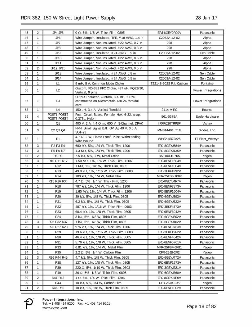
103 2 TP1 TP3 Test Point, RED, THRU-HOLE MOUNT 5010 Keystone 104 4 TP2 TP4 TP5 TP6 Test Point, BLK, THRU-HOLE MOUNT 5011 Keystone 105 1 U1 HiperPFS-2, ESIP16/13 PFS7326H Power Integrations 106 1 U2 IC, REG ZENER SHUNT ADJ SOT-23 LM431AIM3/NOPB National Semi 107 1 U3 HiperLCS, ESIP16/13 LCS702HG Power Integrations 108 1 U4 Optocoupler, 80 V, CTR 80-160%, 4-Mini Flat PC357N1TJ00F Sharp 109 1 U5 OP AMP SINGLE LOW PWR SOT23-5 LM321MF National Semi 110 1 VR1 39 V, 5%, 500 mW, DO-35 1N5259B-T Diodes, Inc. 111 1 VR2 12 V, 5%, 500 mW, DO-213AA (MELF) ZMM5242B-7 Diodes, Inc. 112 1 VR3 18 V, 5%, 500 mW, DO-213AA (MELF) ZMM5248B-7 Diodes, Inc.
114 4
WASHER1 WASHER2 WASHER3 WASHER4
Washer Flat #6, SS, Zinc Plate, 0.267 OD x 0.143 ID x 0.032 Thk 620-6Z Olander
RDR-382, 150 W Street Light Power Supply 28-Jun-17
Page 20 of 82
Power Integrations, Inc. Tel: +1 408 414 9200 Fax: +1 408 414 9201 www.power.com
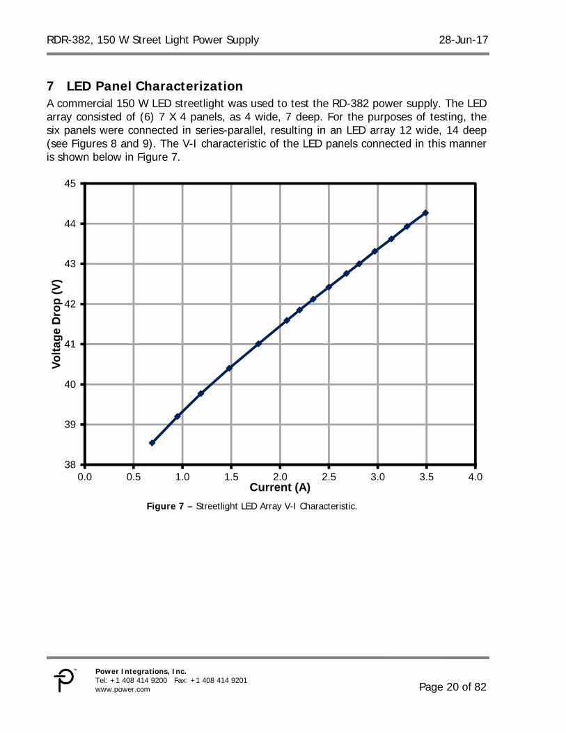
7 LED Panel Characterization A commercial 150 W LED streetlight was used to test the RD-382 power supply. The LED array consisted of (6) 7 X 4 panels, as 4 wide, 7 deep. For the purposes of testing, the six panels were connected in series-parallel, resulting in an LED array 12 wide, 14 deep (see Figures 8 and 9). The V-I characteristic of the LED panels connected in this manner is shown below in Figure 7.
Figure 7 – Streetlight LED Array V-I Characteristic.
38
39
40
41
42
43
44
45
0.0 0.5 1.0 1.5 2.0 2.5 3.0 3.5 4.0
Vo
lta
ge
Dro
p (
V)
Current (A)
28-Jun-17 RDR-382, 150 W Street Light Power Supply
7.1 LED Panel Current Sharing For the purpose of this report, the six LED panels in the street light were partitioned into 3 sections, each section consisting of two LED panels in series. Each panel was internally connected as an array of LEDs 4 wide and 7 deep so that two panels connected in series consisted of an array of LEDS 4 wide by 14 deep. The three sections were connected in parallel, forming a total LED load 12 wide and 14 deep. Using a DC current probe, the current in each 4 wide by 14 deep section was measured to determine the current distribution between sections, with results shown below. 1 2 3
Figure 8 – LED Test Panel Layout. Figure 9 – Array of LEDs in Each Test Panel.
Section # 1 2 3 Current (A) 1.113 A 1.159 A 1.126 A Maximum difference between sections was <5%.
RDR-382, 150 W Street Light Power Supply 28-Jun-17
Page 22 of 82
Power Integrations, Inc. Tel: +1 408 414 9200 Fax: +1 408 414 9201 www.power.com
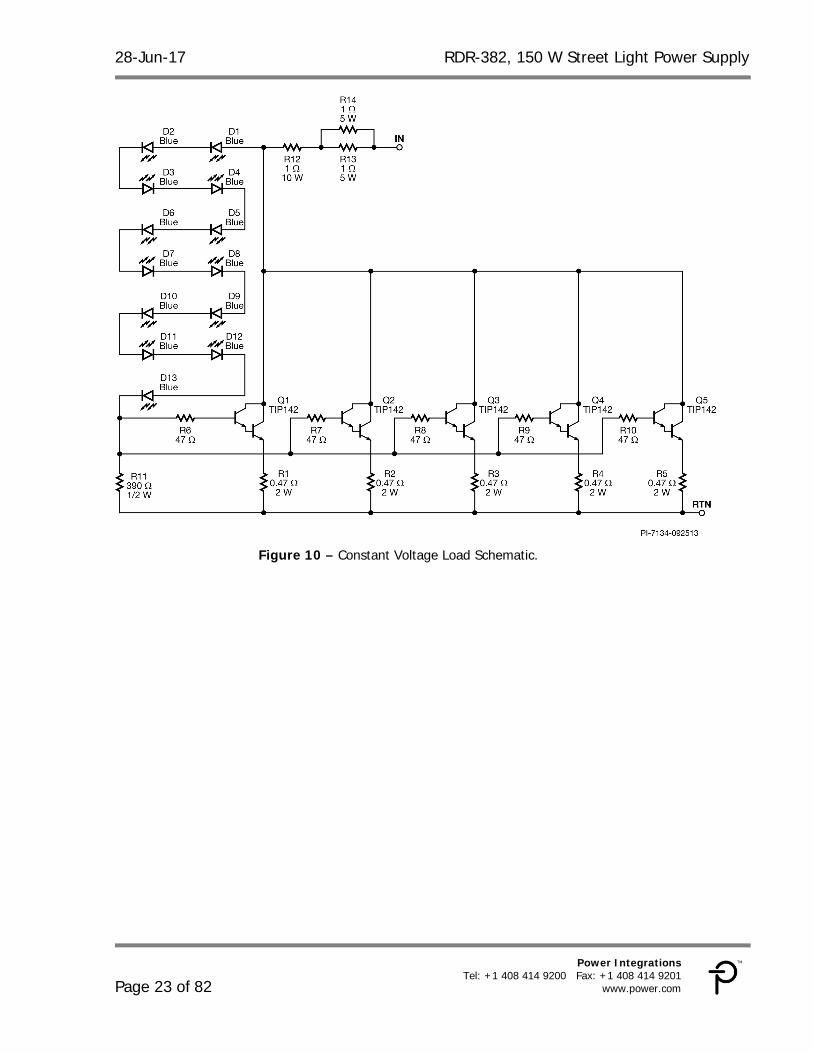
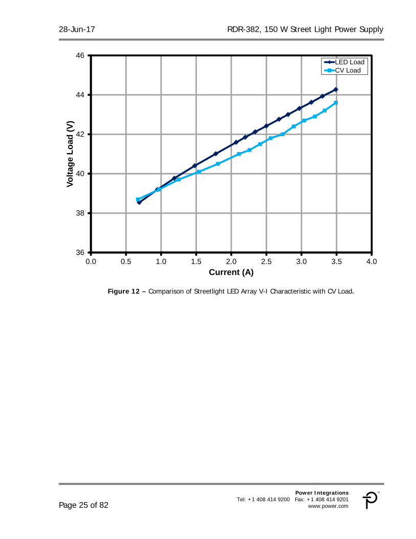
7.2 Constant Voltage Load Since this power supply has a constant current output tailored for a relatively fixed constant voltage load, the usual constant current electronic load cannot be used for testing. For bench testing at maximum power, a constant resistance load can be used, set such that the supply output is at maximum current and an output voltage of 43-44 V, as indicated by the V-I curve shown in Figure 7. Other testing, including dimming and gain-phase, will require the actual LED load or a constant voltage load that closely mimics its characteristics. The streetlight LED as a load was both large and heavy. In order to facilitate EMI and surge testing, a constant voltage load was constructed to emulate the behavior of the LED array in a much smaller package. The circuit is shown in Figure 8. The load consists of paralleled power Darlington transistors Q1-5, each with an emitter resistor (R1-5) to facilitate current sharing. Base resistors R6-10 help prevent oscillation. A string of thirteen 3 mm blue LEDs (D1-13) are used as a voltage reference to mimic the characteristics of the LED panel. Resistor R11 is adjusted to vary the voltage at which the load turns on to match the characteristics of the LED panel. Resistors R12-14 add extra impedance in series with the load to approximate the characteristics of the LED panel. The completed array with heat sink is shown in Figure 9. A small fan was used to cool the heat sink when the load was operated for extended periods at full power. The V-I characteristics of the CV load are shown superimposed on those of the LED array in Figure 10. An electronic load with appropriate rating and a constant voltage option (with some series resistance) could also be used for testing, but this load has the advantage that no external AC power is needed.
28-Jun-17 RDR-382, 150 W Street Light Power Supply
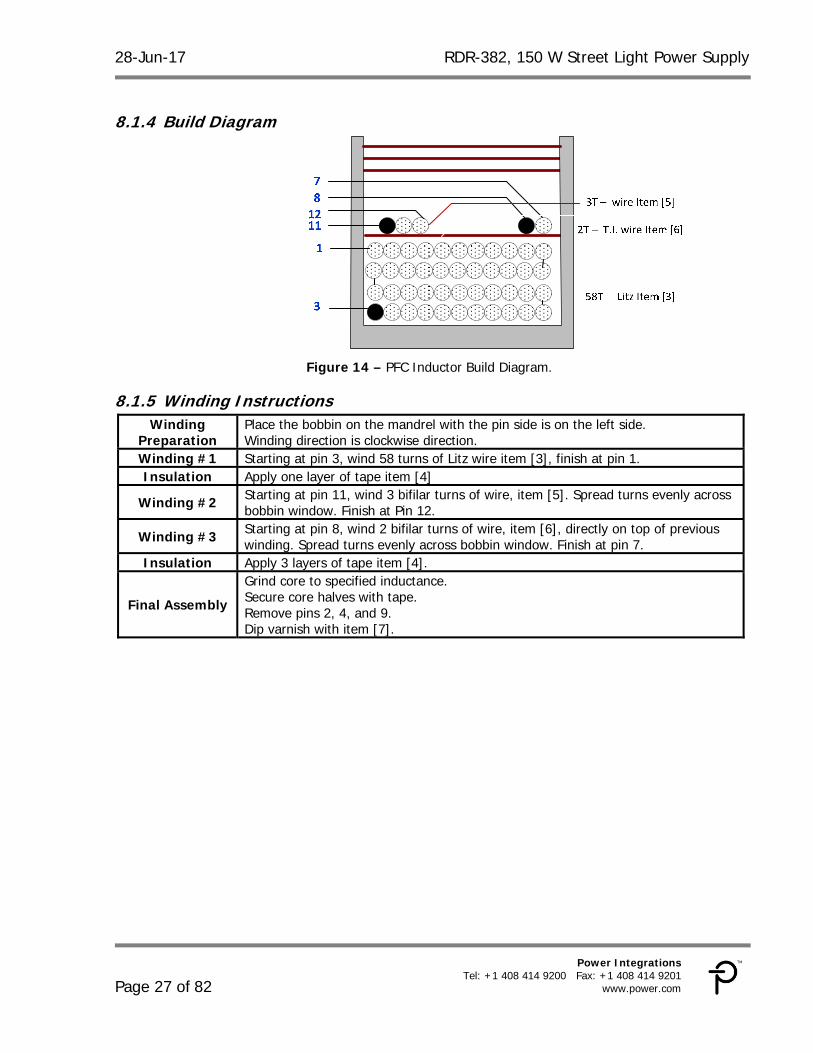
Preparation Place the bobbin on the mandrel with the pin side is on the left side. Winding direction is clockwise direction.
Winding #1 Starting at pin 3, wind 58 turns of Litz wire item [3], finish at pin 1. Insulation Apply one layer of tape item [4]
Winding #2 Starting at pin 11, wind 3 bifilar turns of wire, item [5]. Spread turns evenly across bobbin window. Finish at Pin 12.
Winding #3 Starting at pin 8, wind 2 bifilar turns of wire, item [6], directly on top of previous winding. Spread turns evenly across bobbin window. Finish at pin 7.
Insulation Apply 3 layers of tape item [4].
Final Assembly
Grind core to specified inductance. Secure core halves with tape. Remove pins 2, 4, and 9. Dip varnish with item [7].
RDR-382, 150 W Street Light Power Supply 28-Jun-17
Page 28 of 82
Power Integrations, Inc. Tel: +1 408 414 9200 Fax: +1 408 414 9201 www.power.com
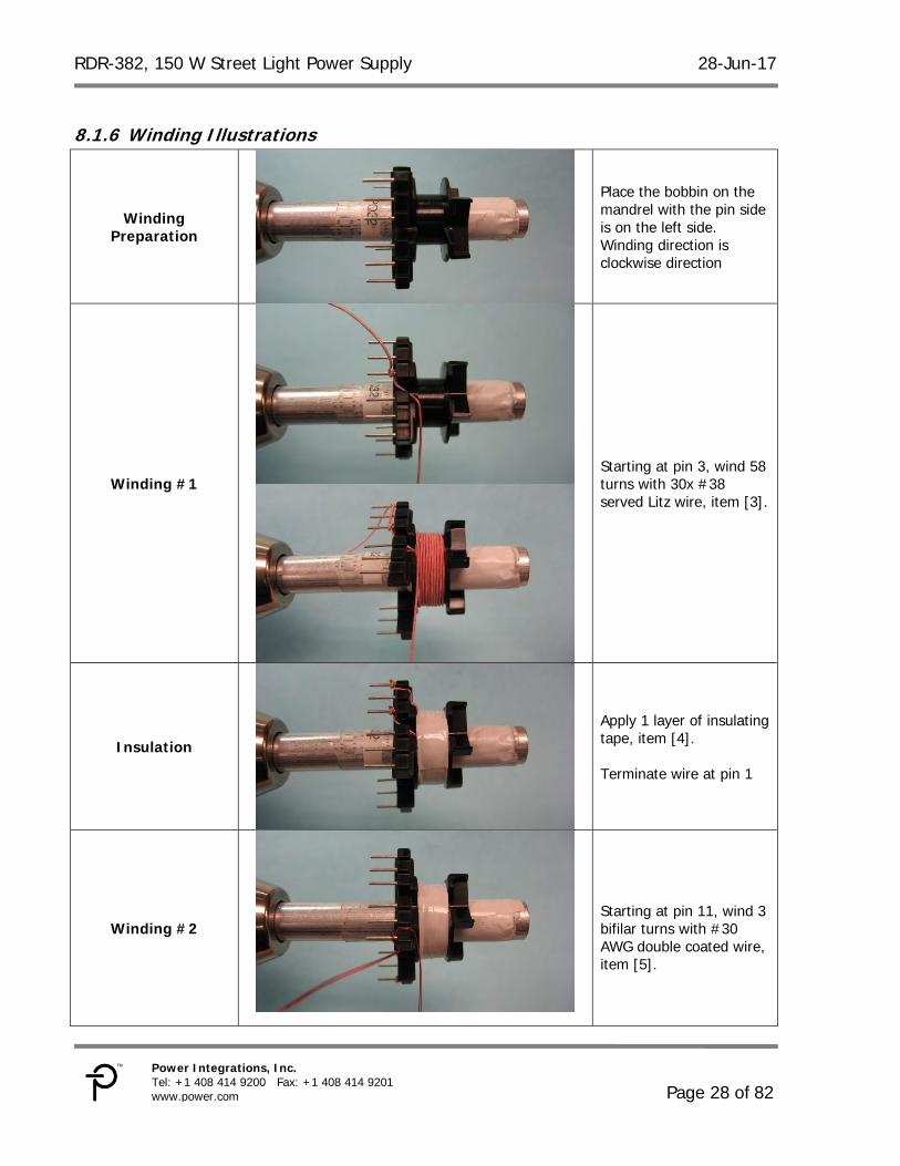
8.1.6 Winding Illustrations
Winding Preparation
Place the bobbin on the mandrel with the pin side is on the left side. Winding direction is clockwise direction
Winding #1
Starting at pin 3, wind 58 turns with 30x #38 served Litz wire, item [3].
Insulation
Apply 1 layer of insulating tape, item [4]. Terminate wire at pin 1
Winding #2
Starting at pin 11, wind 3 bifilar turns with #30 AWG double coated wire, item [5].
28-Jun-17 RDR-382, 150 W Street Light Power Supply
RDR-382, 150 W Street Light Power Supply 28-Jun-17
Page 32 of 82
Power Integrations, Inc. Tel: +1 408 414 9200 Fax: +1 408 414 9201 www.power.com
8.2.4 Build Diagram
Figure 16 – LLC Transformer Build Diagram.
8.2.5 Winding Instructions
Secondary Wire Preparation
Prepare 2 strands of wire item [5] 12” length, tin ends. Label one strand to distinguish from other and designate it as FL1, FL2. Other strand will be designated as FL3 and FL4. Twist these 2 strands together ~20 twists evenly along length leaving 1” free at each end. See pictures below.
WD1 (Primary)
Place the bobbin item [2] on the mandrel with primary chamber on the left side. Note: primary chamber is wider than secondary chamber. Starting on pin 3, wind 29 turns of served Litz wire item [6] in 5 layers, and finish on Pin 1.
WD2A & WD2B (Secondary)
Using unserved Litz assembly prepared in step 1, start with FL1 on pins 5 and FL3 on pin 6, tightly wind 6 turns in secondary chamber. Finish with FL2 on pin 6 and FL4 on pin 8.
Bobbin Cover Slide bobbin cover [3] into grooves in bobbin flanges as shown. Make sure cover is securely seated.
Finish
Remove pins 2, 4 of bobbin. Grind core halves [1] for specified inductance. Assemble and secure core halves using circumferential turn of copper tape [7] as shown, overlap ends, and solder. Solder 3” termination lead of stranded wire item [8] to core band close to pin 4 as shown, secure with two turns of tape item [4].
3
1
5
7
6
8
WD2B: 6T – 165/#42 Unserved Litz
..is twisted and wound in parallel with...
WD2A: 6T – 165/#42 Unserved Litz
WD1: 29T – 125/#44 Served Litz
28-Jun-17 RDR-382, 150 W Street Light Power Supply
Prepare 2 strands of wire item [7] 12” length, tin ends. Label one strand to distinguish from other and designate it as FL1, FL2. Other strand will be designated as FL3 and FL4. Twist these 2 strands together ~20 twists evenly along length leaving 1” free at each end.
WD1
(Primary)
Place the bobbin item [2] on the mandrel with primary chamber on the left side. Note: primary chamber is wider than secondary chamber. Starting on pin 3,
WD1 (Primary) (Cont’d)
Wind 29 turns of served Litz wire item [6] in 5 layers, and finish on pin 1.
FL1
FL2
FL3
FL4
FL1
FL3
FL2
FL4
RDR-382, 150 W Street Light Power Supply 28-Jun-17
Page 34 of 82
Power Integrations, Inc. Tel: +1 408 414 9200 Fax: +1 408 414 9201 www.power.com
WD2A & WD2B
(Secondary)
Using unserved Litz assembly prepared in step 1, start with FL1 on pins 5 and FL3 on pin 6, tightly wind 6 turns in secondary chamber. Finish with FL2 on pin 6 and FL4 on pin 8.
28-Jun-17 RDR-382, 150 W Street Light Power Supply
Slide bobbin cover [3] into grooves in bobbin flanges as shown. Make sure cover is securely seated.
Finish
Remove pins 2, 4 of bobbin. Grind core halves [1] for specified inductance. Assemble and secure core halves using circumferential turn of copper tape [7] as shown, overlap ends, and solder. Solder 3” termination lead of stranded wire item [8] to core band close to pin 4 as shown, secure with two turns of tape item [4].
RDR-382, 150 W Street Light Power Supply 28-Jun-17
Page 36 of 82
Power Integrations, Inc. Tel: +1 408 414 9200 Fax: +1 408 414 9201 www.power.com
28-Jun-17 RDR-382, 150 W Street Light Power Supply
Inductance Pins FL1-FL2, all other windings open, measured at 100 kHz, 0.4 VRMS.
300 nH, ±15%
8.3.3 Material List Item Description [1] Powdered Iron Toroidal Core: Micrometals T30-26. [2] Magnet wire: #19 AWG Solderable Double Coated.
8.3.4 Construction Details
Figure 16 – Finished Part, Front View. Tin Leads to within ~ 1/8” of Toroid Body.
3T – 19AWG
FL1
FL2
RDR-382, 150 W Street Light Power Supply 28-Jun-17
Page 38 of 82
Power Integrations, Inc. Tel: +1 408 414 9200 Fax: +1 408 414 9201 www.power.com
9 PFC Design Spreadsheet In this design, the spreadsheet generated warnings concerning the high value of KP selected, and for the operating current density of the Litz wire size selected for this design. A high KP value can impact power factor and distortion, so a design generating this warning should be checked for any adverse impact. This design met the requirements for power factor and harmonic distortion, and the high KP value allowed selection of a ferrite core for the PFC inductor, with consequent efficiency improvement. A warning for current density indicates that the design should be checked in its initial stages for excessive temperature rise in the PFC inductor. The guidelines incorporated the spreadsheet are conservative, so that a warning does not necessarily mean that a given design will fail thermally. The measured temperature rise for this design was satisfactory.
Hiper_PFS-II_Boost_062013; Rev.1.1; Copyright Power Integrations
2013
INPUT INFO OUTPUT UNITS Hiper_PFS-II_Boost_062013_Rev1-1.xls; Continuous Mode Boost Converter Design Spreadsheet
Enter Applications Variables Input Voltage Range Universal Input voltage range VACMIN 90 V Minimum AC input voltage VACMAX 265 V Maximum AC input voltage VBROWNIN 76.69 Expected Minimum Brown-in Voltage VBROWNOUT 68.33 V Specify brownout voltage. VO 385.00 V Nominal Output voltage PO 160.00 160.00 W Nominal Output power fL 50 Hz Line frequency TA Max 40 deg C Maximum ambient temperature
n 0.93 Enter the efficiency estimate for the boost converter at VACMIN
KP 0.750 Warning 0.75 !!!Warning. KP is too high. Reduce KP to below 0.675 for Ferrite cores and to below 0.8 for other core types
VO_MIN 365.75 V Minimum Output voltage VO_RIPPLE_MAX 20 V Maximum Output voltage ripple tHOLDUP 18.00 18 ms Holdup time
VHOLDUP_MIN 310 V Minimum Voltage Output can drop to during holdup
I_INRUSH 40 A Maximum allowable inrush current
Forced Air Cooling no no Enter "Yes" for Forced air cooling. Otherwise enter "No"
PFS Parameters PFS Part Number PFS7326H PFS7326H Selected PFS device
MODE EFFICIENCY EFFICIENCY Mode of operation of PFS. For full mode enter "FULL" otherwise enter "EFFICIENCY" to indicate efficiency mode
R_RPIN 49.9 k-ohms R pin resistor value
28-Jun-17 RDR-382, 150 W Street Light Power Supply
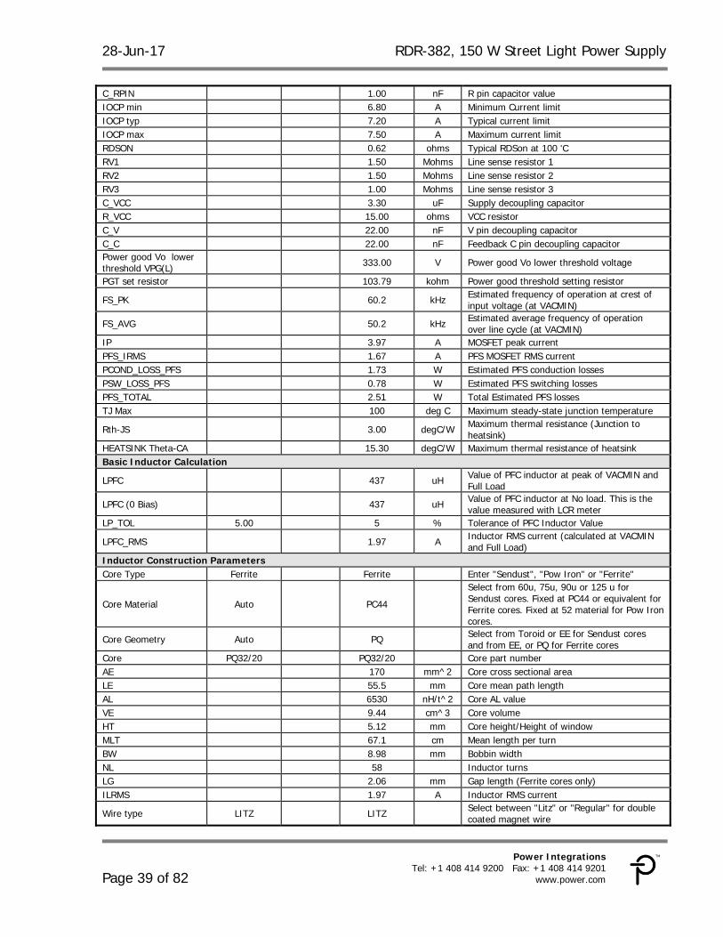
C_RPIN 1.00 nF R pin capacitor value IOCP min 6.80 A Minimum Current limit IOCP typ 7.20 A Typical current limit IOCP max 7.50 A Maximum current limit RDSON 0.62 ohms Typical RDSon at 100 'C RV1 1.50 Mohms Line sense resistor 1 RV2 1.50 Mohms Line sense resistor 2 RV3 1.00 Mohms Line sense resistor 3 C_VCC 3.30 uF Supply decoupling capacitor R_VCC 15.00 ohms VCC resistor C_V 22.00 nF V pin decoupling capacitor C_C 22.00 nF Feedback C pin decoupling capacitor Power good Vo lower threshold VPG(L) 333.00 V Power good Vo lower threshold voltage
PGT set resistor 103.79 kohm Power good threshold setting resistor
FS_PK 60.2 kHz Estimated frequency of operation at crest of input voltage (at VACMIN)
FS_AVG 50.2 kHz Estimated average frequency of operation over line cycle (at VACMIN)
IP 3.97 A MOSFET peak current PFS_IRMS 1.67 A PFS MOSFET RMS current PCOND_LOSS_PFS 1.73 W Estimated PFS conduction losses PSW_LOSS_PFS 0.78 W Estimated PFS switching losses PFS_TOTAL 2.51 W Total Estimated PFS losses TJ Max 100 deg C Maximum steady-state junction temperature
Rth-JS 3.00 degC/W Maximum thermal resistance (Junction to heatsink)
HEATSINK Theta-CA 15.30 degC/W Maximum thermal resistance of heatsink Basic Inductor Calculation
LPFC 437 uH Value of PFC inductor at peak of VACMIN and Full Load
LPFC (0 Bias) 437 uH Value of PFC inductor at No load. This is the value measured with LCR meter
LP_TOL 5.00 5 % Tolerance of PFC Inductor Value
LPFC_RMS 1.97 A Inductor RMS current (calculated at VACMIN and Full Load)
Inductor Construction Parameters Core Type Ferrite Ferrite Enter "Sendust", "Pow Iron" or "Ferrite"
Core Material Auto PC44
Select from 60u, 75u, 90u or 125 u for Sendust cores. Fixed at PC44 or equivalent for Ferrite cores. Fixed at 52 material for Pow Iron cores.
Core Geometry Auto PQ Select from Toroid or EE for Sendust cores and from EE, or PQ for Ferrite cores
Core PQ32/20 PQ32/20 Core part number AE 170 mm^2 Core cross sectional area LE 55.5 mm Core mean path length AL 6530 nH/t^2 Core AL value VE 9.44 cm^3 Core volume HT 5.12 mm Core height/Height of window MLT 67.1 cm Mean length per turn BW 8.98 mm Bobbin width NL 58 Inductor turns LG 2.06 mm Gap length (Ferrite cores only) ILRMS 1.97 A Inductor RMS current
Wire type LITZ LITZ Select between "Litz" or "Regular" for double coated magnet wire
RDR-382, 150 W Street Light Power Supply 28-Jun-17
Page 40 of 82
Power Integrations, Inc. Tel: +1 408 414 9200 Fax: +1 408 414 9201 www.power.com
AWG 38 38 AWG Inductor wire gauge Filar 30 30 Inductor wire number of parallel strands OD 0.102 mm Outer diameter of single strand of wire
AC Resistance Ratio 1.01 Ratio of AC resistance to the DC resistance (using Dowell curves)
J Warning 8.11 A/mm^2
!!! Warning Current density is too high and may cause heating in the inductor wire. Reduce J
BP_TARGET 3500 Gauss Target flux density at VACMIN (Ferrite cores only)
BM 1757 Gauss Maximum operating flux density BP 3487 Gauss Peak Flux density (Estimated at VBROWNOUT) LPFC_CORE_LOSS 0.09 W Estimated Inductor core Loss LPFC_COPPER_LOSS 1.80 W Estimated Inductor copper losses LPFC_TOTAL LOSS 1.89 W Total estimated Inductor Losses FIT 79.72% % Estimated FIT factor for inductor Layers 5.1 Estimated layers in winding Critical Parameters IRMS 1.91 A AC input RMS current IO_AVG 0.42 A Output average current Output Diode (DO) Part Number Auto INTERNAL PFC Diode Part Number
Type SPECIAL Diode Type - Special - Diodes specially catered for PFC applications, SiC - Silicon Carbide type, UF - Ultrafast recovery type
Manufacturer PI Diode Manufacturer VRRM 600 V Diode rated reverse voltage IF 3 A Diode rated forward current TRR 31 ns Diode Reverse recovery time VF 1.47 V Diode rated forward voltage drop PCOND_DIODE 0.61 W Estimated Diode conduction losses PSW_DIODE 0.16 W Estimated Diode switching losses P_DIODE 0.77 W Total estimated Diode losses TJ Max 100 deg C Maximum steady-state operating temperature
Rth-JS 3.85 degC/W Maximum thermal resistance (Junction to heatsink)
HEATSINK Theta-CA 15.30 degC/W Maximum thermal resistance of heatsink Output Capacitor CO Auto 120.00 uF Minimum value of Output capacitance
VO_RIPPLE_EXPECTED 11.9 V Expected ripple voltage on Output with selected Output capacitor
T_HOLDUP_EXPECTED 19.5 ms Expected holdup time with selected Output capacitor
ESR_LF 1.38 ohms Low Frequency Capacitor ESR ESR_HF 0.55 ohms High Frequency Capacitor ESR IC_RMS_LF 0.29 A Low Frequency Capacitor RMS current IC_RMS_HF 0.85 A High Frequency Capacitor RMS current
CO_LF_LOSS 0.12 W Estimated Low Frequency ESR loss in Output capacitor
CO_HF_LOSS 0.39 W Estimated High frequency ESR loss in Output capacitor
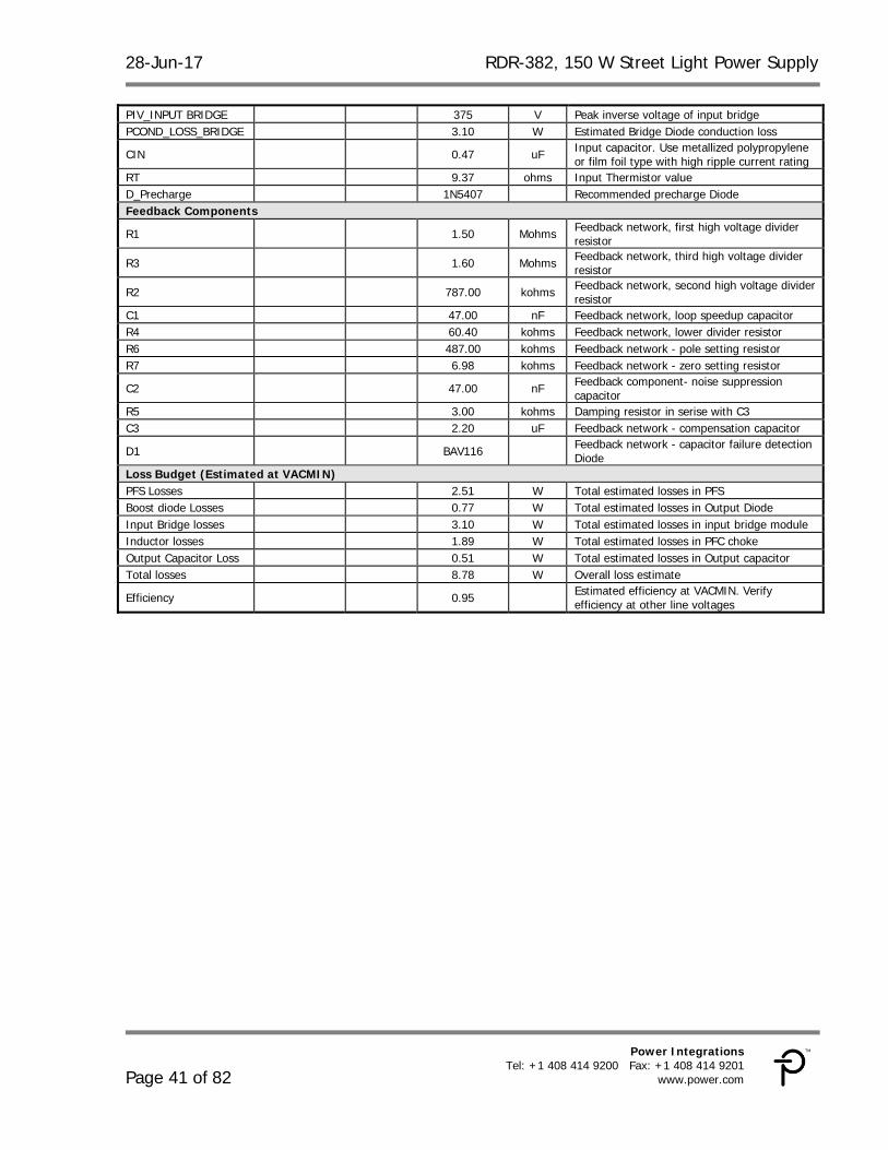
Total CO LOSS 0.51 W Total estimated losses in Output Capacitor Input Bridge (BR1) and Fuse (F1) I^2t Rating 8.43 A^2s Minimum I^2t rating for fuse Fuse Current rating 3.00 A Minimum Current rating of fuse VF 0.90 V Input bridge Diode forward Diode drop IAVG 1.86 A Input average current at 70 VAC.
28-Jun-17 RDR-382, 150 W Street Light Power Supply
Loss Budget (Estimated at VACMIN) PFS Losses 2.51 W Total estimated losses in PFS Boost diode Losses 0.77 W Total estimated losses in Output Diode Input Bridge losses 3.10 W Total estimated losses in input bridge module Inductor losses 1.89 W Total estimated losses in PFC choke Output Capacitor Loss 0.51 W Total estimated losses in Output capacitor Total losses 8.78 W Overall loss estimate
Efficiency 0.95 Estimated efficiency at VACMIN. Verify efficiency at other line voltages
RDR-382, 150 W Street Light Power Supply 28-Jun-17
Page 42 of 82
Power Integrations, Inc. Tel: +1 408 414 9200 Fax: +1 408 414 9201 www.power.com
INPUTS INFO OUTPUTS UNITS HiperLCS_040312_Rev1-3.xls; HiperLCS Half-Bridge, Continuous mode LLC Resonant Converter Design Spreadsheet
Enter Input Parameters Vbulk_nom 380 V Nominal LLC input voltage
Vbrownout 287 287 V Brownout threshold voltage. HiperLCS will shut down if voltage drops below this value. Allowable value is between 65% and 76% of Vbulk_nom. Set to 65% for max holdup time
Vbrownin 362 V Startup threshold on bulk capacitor VOV_shut 476 V OV protection on bulk voltage VOV_restart 459 V Restart voltage after OV protection.
CBULK 120.00 120 uF Minimum value of bulk cap to meet holdup time requirement; Adjust holdup time and Vbrownout to change bulk cap value
tHOLDUP 23.8 ms Bulk capacitor hold up time Enter LLC (secondary) outputs The spreadsheet assumes AC stacking of the secondaries
VO1 43.00 43.0 V Main Output Voltage. Spreadsheet assumes that this is the regulated output
IO1 3.50 3.5 A Main output maximum current VD1 0.70 0.70 V Forward voltage of diode in Main output PO1 151 W Output Power from first LLC output VO2 0.0 V Second Output Voltage IO2 0.0 A Second output current VD2 0.70 V Forward voltage of diode used in second output PO2 0.00 W Output Power from second LLC output P_LLC 151 W Specified LLC output power LCS Device Selection Device LCS702 LCS702 LCS Device RDS-ON (MAX) 1.39 ohms RDS-ON (max) of selected device Coss 250 pF Equivalent Coss of selected device Cpri 40 pF Stray Capacitance at transformer primary Pcond_loss 1.5 W Conduction loss at nominal line and full load Tmax-hs 90 deg C Maximum heatsink temperature
Theta J-HS 9.1 deg C/W Thermal resistance junction to heatsink (with grease and no insulator)
Expected Junction temperature 103 deg C Expectd Junction temperature Ta max 50 deg C Expected max ambient temperature Theta HS-A 27 deg C/W Required thermal resistance heatsink to ambient LLC Resonant Parameter and Transformer Calculations (generates red curve)
Vres_target 380 380 V Desired Input voltage at which power train operates at resonance. If greater than Vbulk_nom, LLC operates below resonance at VBULK.
Po 153 W LLC output power including diode loss
Vo 43.70 V Main Output voltage (includes diode drop) for calculating Nsec and turns ratio
f_target 250 kHz Desired switching frequency at Vbulk_nom. 66 kHz to 300 kHz, recommended 180-250 kHz
Lpar 291 uH Parallel inductance. (Lpar = Lopen - Lres for integrated transformer; Lpar = Lmag for non-integrated low-leakage transformer)
Lpri 341 uH
Primary open circuit inductance for integrated transformer; for low-leakage transformer it is sum of primary inductance and series inductor. If left blank, auto-calculation shows value necessary for slight loss of ZVS at ~80% of Vnom
Lres 50.00 50.0 uH Series inductance or primary leakage inductance of integrated transformer; if left blank auto-calculation is for K=4
28-Jun-17 RDR-382, 150 W Street Light Power Supply
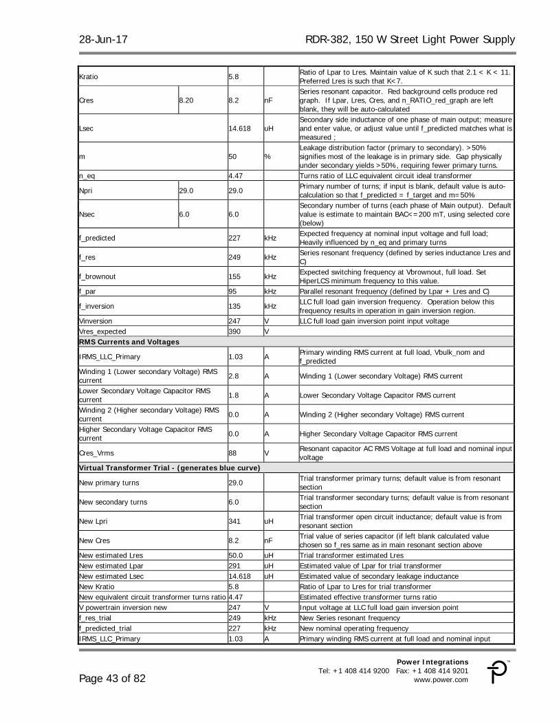
Kratio 5.8 Ratio of Lpar to Lres. Maintain value of K such that 2.1 < K < 11. Preferred Lres is such that K<7.
Cres 8.20 8.2 nF Series resonant capacitor. Red background cells produce red graph. If Lpar, Lres, Cres, and n_RATIO_red_graph are left blank, they will be auto-calculated
Lsec 14.618 uH Secondary side inductance of one phase of main output; measure and enter value, or adjust value until f_predicted matches what is measured ;
m 50 % Leakage distribution factor (primary to secondary). >50% signifies most of the leakage is in primary side. Gap physically under secondary yields >50%, requiring fewer primary turns.
n_eq 4.47 Turns ratio of LLC equivalent circuit ideal transformer
Npri 29.0 29.0 Primary number of turns; if input is blank, default value is auto-calculation so that f_predicted = f_target and m=50%
Nsec 6.0 6.0 Secondary number of turns (each phase of Main output). Default value is estimate to maintain BAC<=200 mT, using selected core (below)
f_predicted 227 kHz Expected frequency at nominal input voltage and full load; Heavily influenced by n_eq and primary turns
f_res 249 kHz Series resonant frequency (defined by series inductance Lres and C)
f_brownout 155 kHz Expected switching frequency at Vbrownout, full load. Set HiperLCS minimum frequency to this value.
f_par 95 kHz Parallel resonant frequency (defined by Lpar + Lres and C)
f_inversion 135 kHz LLC full load gain inversion frequency. Operation below this frequency results in operation in gain inversion region.
Vinversion 247 V LLC full load gain inversion point input voltage Vres_expected 390 V RMS Currents and Voltages
IRMS_LLC_Primary 1.03 A Primary winding RMS current at full load, Vbulk_nom and f_predicted
Winding 1 (Lower secondary Voltage) RMS current 2.8 A Winding 1 (Lower secondary Voltage) RMS current
Lower Secondary Voltage Capacitor RMS current 1.8 A Lower Secondary Voltage Capacitor RMS current
Winding 2 (Higher secondary Voltage) RMS current 0.0 A Winding 2 (Higher secondary Voltage) RMS current
Higher Secondary Voltage Capacitor RMS current 0.0 A Higher Secondary Voltage Capacitor RMS current
Cres_Vrms 88 V Resonant capacitor AC RMS Voltage at full load and nominal input voltage
Virtual Transformer Trial - (generates blue curve)
New primary turns 29.0 Trial transformer primary turns; default value is from resonant section
New secondary turns 6.0 Trial transformer secondary turns; default value is from resonant section
New Lpri 341 uH Trial transformer open circuit inductance; default value is from resonant section
New Cres 8.2 nF Trial value of series capacitor (if left blank calculated value chosen so f_res same as in main resonant section above
New estimated Lres 50.0 uH Trial transformer estimated Lres New estimated Lpar 291 uH Estimated value of Lpar for trial transformer New estimated Lsec 14.618 uH Estimated value of secondary leakage inductance New Kratio 5.8 Ratio of Lpar to Lres for trial transformer New equivalent circuit transformer turns ratio 4.47 Estimated effective transformer turns ratio V powertrain inversion new 247 V Input voltage at LLC full load gain inversion point f_res_trial 249 kHz New Series resonant frequency f_predicted_trial 227 kHz New nominal operating frequency IRMS_LLC_Primary 1.03 A Primary winding RMS current at full load and nominal input
RDR-382, 150 W Street Light Power Supply 28-Jun-17
Page 44 of 82
Power Integrations, Inc. Tel: +1 408 414 9200 Fax: +1 408 414 9201 www.power.com
voltage (Vbulk) and f_predicted_trial Winding 1 (Lower secondary Voltage) RMS current 2.7 A RMS current through Output 1 winding, assuming half sinusoidal
waveshape Lower Secondary Voltage Capacitor RMS current 1.6 A Lower Secondary Voltage Capacitor RMS current
Winding 2 (Higher secondary Voltage) RMS current 2.7 A RMS current through Output 2 winding; Output 1 winding is AC
stacked on top of Output 2 winding Higher Secondary Voltage Capacitor RMS current 0.0 A Higher Secondary Voltage Capacitor RMS current
Vres_expected_trial 390 V Expected value of input voltage at which LLC operates at resonance.
Transformer Core Calculations (Calculates From Resonant Parameter Section) Transformer Core Auto EEL25 Transformer Core Ae 0.76 0.76 cm^2 Enter transformer core cross-sectional area Ve 5.35 5.35 cm^3 Enter the volume of core Aw 107.9 mm^2 Area of window Bw 15.50 15.5 mm Total Width of Bobbin
Loss density 200.0 mW/cm^3 Enter the loss per unit volume at the switching frequency and BAC (Units same as kW/m^3)
MLT 5.20 5.2 cm Mean length per turn Nchambers 2 2 Number of Bobbin chambers Wsep 1.60 1.6 mm Winding separator distance (will result in loss of winding area) Ploss 1.1 W Estimated core loss Bpkfmin 155 mT First Quadrant peak flux density at minimum frequency.
BAC 211 mT AC peak to peak flux density (calculated at f_predicted, Vbulk at full load)
Primary Winding Npri 29.0 Number of primary turns; determined in LLC resonant section Primary gauge 44 AWG Individual wire strand gauge used for primary winding Equivalent Primary Metric Wire gauge 0.050 mm Equivalent diameter of wire in metric units
Primary litz strands 125 125 Number of strands in Litz wire; for non-litz primary winding, set to 1
Primary Winding Allocation Factor 50 % Primary window allocation factor - percentage of winding space allocated to primary
AW_P 48 mm^2 Winding window area for primary Fill Factor 25% % % Fill factor for primary winding (typical max fill is 60%) Resistivity_25 C_Primary 75.42 m-ohm/m Resistivity in milli-ohms per meter Primary DCR 25 C 113.73 m-ohm Estimated resistance at 25 C
Primary DCR 100 C 152.40 m-ohm Estimated resistance at 100 C (approximately 33% higher than at 25 C)
Primary RMS current 1.03 A Measured RMS current through the primary winding
ACR_Trf_Primary 259.81 m-ohm Measured AC resistance (at 100 kHz, room temperature), multiply by 1.33 to approximate 100 C winding temperature
Primary copper loss 0.27 W Total primary winding copper loss at 85 C Primary Layers 3.02 Number of layers in primary Winding Secondary Winding 1 (Lower secondary voltage OR Single output)
Note - Power loss calculations are for each winding half of secondary
Output Voltage 43.00 V Output Voltage (assumes AC stacked windings) Sec 1 Turns 6.00 Secondary winding turns (each phase )
Sec 1 RMS current (total, AC+DC) 2.8 A RMS current through Output 1 winding, assuming half sinusoidal waveshape
Winding current (DC component) 1.75 A DC component of winding current Winding current (AC RMS component) 2.17 A AC component of winding current Sec 1 Wire gauge 42 AWG Individual wire strand gauge used for secondary winding Equivalent secondary 1 Metric Wire gauge 0.060 mm Equivalent diameter of wire in metric units
Sec 1 litz strands 165 165 Number of strands used in Litz wire; for non-litz non-integrated transformer set to 1
28-Jun-17 RDR-382, 150 W Street Light Power Supply
Resistivity_25 C_sec1 35.93 m-ohm/m Resistivity in milli-ohms per meter DCR_25C_Sec1 11.21 m-ohm Estimated resistance per phase at 25 C (for reference)
DCR_100C_Sec1 15.02 m-ohm Estimated resistance per phase at 100 C (approximately 33% higher than at 25 C)
DCR_Ploss_Sec1 0.37 W Estimated Power loss due to DC resistance (both secondary phases)
ACR_Sec1 15.25 m-ohm
Measured AC resistance per phase (at 100 kHz, room temperature), multiply by 1.33 to approximate 100 C winding temperature. Default value of ACR is twice the DCR value at 100 C
ACR_Ploss_Sec1 0.14 W Estimated AC copper loss (both secondary phases) Total winding 1 Copper Losses 0.51 W Total (AC + DC) winding copper loss for both secondary phases Capacitor RMS current 1.8 A Output capacitor RMS current Co1 1.8 uF Secondary 1 output capacitor Capacitor ripple voltage 3.0 % Peak to Peak ripple voltage on secondary 1 output capacitor
Output rectifier RMS Current 2.8 A Schottky losses are a stronger function of load DC current. Sync Rectifier losses are a function of RMS current
Secondary 1 Layers 1.00 Number of layers in secondary 1 Winding
Secondary Winding 2 (Higher secondary voltage) Note - Power loss calculations are for each winding half of secondary
Output Voltage 0.00 V Output Voltage (assumes AC stacked windings)
Sec 2 Turns 0.00 Secondary winding turns (each phase) AC stacked on top of secondary winding 1
Sec 2 RMS current (total, AC+DC) 2.8 A RMS current through Output 2 winding; Output 1 winding is AC stacked on top of Output 2 winding
Winding current (DC component) 0.0 A DC component of winding current Winding current (AC RMS component) 0.0 A AC component of winding current Sec 2 Wire gauge 42 AWG Individual wire strand gauge used for secondary winding Equivalent secondary 2 Metric Wire gauge 0.060 mm Equivalent diameter of wire in metric units
Sec 2 litz strands 0 Number of strands used in Litz wire; for non-litz non-integrated transformer set to 1
Resistivity_25 C_sec2 59292.53 m-ohm/m Resistivity in milli-ohms per meter Transformer Secondary MLT 5.20 cm Mean length per turn DCR_25C_Sec2 0.00 m-ohm Estimated resistance per phase at 25 C (for reference)
DCR_100C_Sec2 0.00 m-ohm Estimated resistance per phase at 100 C (approximately 33% higher than at 25 C)
DCR_Ploss_Sec1 0.00 W Estimated Power loss due to DC resistance (both secondary halves)
ACR_Sec2 0.00 m-ohm
Measured AC resistance per phase (at 100 kHz, room temperature), multiply by 1.33 to approximate 100 C winding temperature. Default value of ACR is twice the DCR value at 100 C
ACR_Ploss_Sec2 0.00 W Estimated AC copper loss (both secondary halves) Total winding 2 Copper Losses 0.00 W Total (AC + DC) winding copper loss for both secondary halves Capacitor RMS current 0.0 A Output capacitor RMS current Co2 N/A uF Secondary 2 output capacitor Capacitor ripple voltage N/A % Peak to Peak ripple voltage on secondary 1 output capacitor
Output rectifier RMS Current 0.0 A Schottky losses are a stronger function of load DC current. Sync Rectifier losses are a function of RMS current
Secondary 2 Layers 1.00 Number of layers in secondary 2 Winding Transformer Loss Calculations Does not include fringing flux loss from gap Primary copper loss (from Primary section) 0.27 W Total primary winding copper loss at 85 C Secondary copper Loss 0.51 W Total copper loss in secondary winding Transformer total copper loss 0.78 W Total copper loss in transformer (primary + secondary) AW_S 48.38 mm^2 Area of window for secondary winding
Secondary Fill Factor 19% % % Fill factor for secondary windings; typical max fill is 60% for served and 75% for unserved Litz
RDR-382, 150 W Street Light Power Supply 28-Jun-17
Page 46 of 82
Power Integrations, Inc. Tel: +1 408 414 9200 Fax: +1 408 414 9201 www.power.com
Signal Pins Resistor Values
f_min 155 kHz Minimum frequency when optocoupler is cut-off. Only change this variable based on actual bench measurements
Dead Time 320 ns Dead time
Burst Mode 1 1 Select Burst Mode: 1, 2, and 3 have hysteresis and have different frequency thresholds
f_max 847 kHz Max internal clock frequency, dependent on dead-time setting. Is also start-up frequency
f_burst_start 382 kHz Lower threshold frequency of burst mode, provides hysteresis. This is switching frequency at restart after a bursting off-period
f_burst_stop 437 kHz Upper threshold frequency of burst mode; This is switching frequency at which a bursting off-period stops
DT/BF pin upper divider resistor 6.79 k-ohms Resistor from DT/BF pin to VREF pin DT/BF pin lower divider resistor 129 k-ohms Resistor from DT/BF pin to G pin
Rstart 5.79 k-ohms Start-up resistor - resistor in series with soft-start capacitor; equivalent resistance from FB to VREF pins at startup. Use default value unless additional start-up delay is desired.
Start up delay 0.0 ms Start-up delay; delay before switching begins. Reduce R_START to increase delay
Rfmin 46.2 k-ohms Resistor from VREF pin to FB pin, to set min operating frequency; This resistor plus Rstart determine f_MIN. Includes 7% HiperLCS frequency tolerance to ensure f_min is below f_brownout
C_softstart 0.33 uF Softstart capacitor. Recommended values are between 0.1 uF and 0.47 uF
Ropto 1.2 k-ohms Resistor in series with opto emitter OV/UV pin lower resistor 19.60 19.6 k-ohm Lower resistor in OV/UV pin divider OV/UV pin upper resistor 2.93 M-ohm Total upper resistance in OV/UV pin divider LLC Capacitive Divider Current Sense Circuit
Slow current limit 2.35 A 8-cycle current limit - check positive half-cycles during brownout and startup
Fast current limit 4.24 A 1-cycle current limit - check positive half-cycles during startup
LLC sense capacitor 47 pF HV sense capacitor, forms current divider with main resonant capacitor
RLLC sense resistor 37.3 ohms LLC current sense resistor, senses current in sense capacitor
IS pin current limit resistor 220 ohms Limits current from sense resistor into IS pin when voltage on sense R is < -0.5V
IS pin noise filter capacitor 1.0 nF IS pin bypass capacitor; forms a pole with IS pin current limit capacitor
IS pin noise filter pole frequency 724 kHz This pole attenuates IS pin signal Loss Budget LCS device Conduction loss 1.5 W Conduction loss at nominal line and full load Output diode Loss 2.5 W Estimated diode losses Transformer estimated total copper loss 0.78 W Total copper loss in transformer (primary + secondary) Transformer estimated total core loss 1.1 W Estimated core loss Total transformer losses 1.9 W Total transformer losses Total estimated losses 5.8 W Total losses in LLC stage Estimated Efficiency 96% % Estimated efficiency PIN 156 W LLC input power
28-Jun-17 RDR-382, 150 W Street Light Power Supply
12 RD-382 Performance Data All measurements were taken at room temperature and 60 Hz (input frequency) unless otherwise specified. Output voltage measurements were taken at the output connectors.
12.1 LLC Stage Efficiency To make this measurement, the LLC stage was supplied by connecting an external 380 VDC source across bulk capacitor C14, with a 2-channel bench supply to source the primary and secondary bias voltages. The output of the supply was used to power the LED streetlight described in Section 7, and the dimming input of the supply was used to program the current delivered to this load in order to vary the output power.
RDR-382, 150 W Street Light Power Supply 28-Jun-17
Page 54 of 82
Power Integrations, Inc. Tel: +1 408 414 9200 Fax: +1 408 414 9201 www.power.com
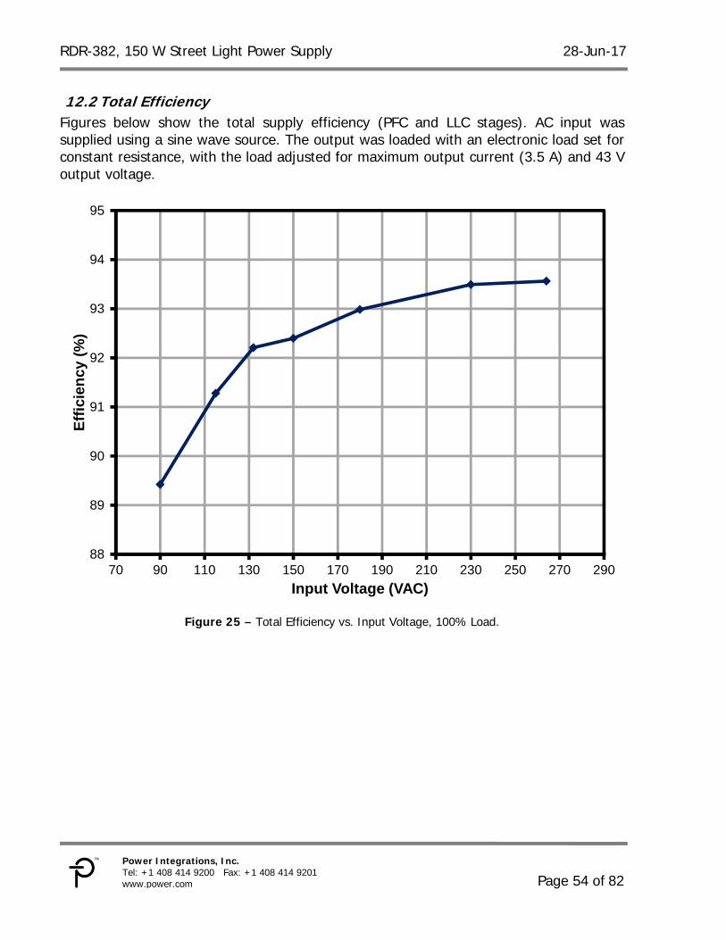
12.2 Total Efficiency Figures below show the total supply efficiency (PFC and LLC stages). AC input was supplied using a sine wave source. The output was loaded with an electronic load set for constant resistance, with the load adjusted for maximum output current (3.5 A) and 43 V output voltage.
Figure 25 – Total Efficiency vs. Input Voltage, 100% Load.
88
89
90
91
92
93
94
95
70 90 110 130 150 170 190 210 230 250 270 290
Eff
icie
ncy
(%
)
Input Voltage (VAC)
28-Jun-17 RDR-382, 150 W Street Light Power Supply
12.3 Power Factor Power factor measurements were made using a sine wave AC source and a constant resistance electronic load as described in section 12.2.
Figure 26 – Power Factor vs. Input Voltage, 100% Load.
0.90
0.92
0.94
0.96
0.98
1.00
1.02
1.04
70 90 110 130 150 170 190 210 230 250 270 290
Po
wer
Fac
tor
Input Voltage (VAC)
RDR-382, 150 W Street Light Power Supply 28-Jun-17
Page 56 of 82
Power Integrations, Inc. Tel: +1 408 414 9200 Fax: +1 408 414 9201 www.power.com
12.4 Harmonic Distribution Input current harmonic distribution was measured using a sine wave source and an LED load (Section 7).
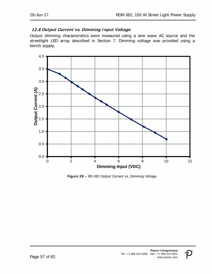
12.6 Output Current vs. Dimming Input Voltage Output dimming characteristics were measured using a sine wave AC source and the streetlight LED array described in Section 7. Dimming voltage was provided using a bench supply.
Figure 28 – RD-382 Output Current vs. Dimming Voltage.
0.0
0.5
1.0
1.5
2.0
2.5
3.0
3.5
4.0
0 2 4 6 8 10 12
Ou
tpu
t C
urr
ent
(A)
Dimming Input (VDC)
RDR-382, 150 W Street Light Power Supply 28-Jun-17
Page 58 of 82
Power Integrations, Inc. Tel: +1 408 414 9200 Fax: +1 408 414 9201 www.power.com
13 Waveforms
13.1 Input Current, 100% Load
Figure 29 – Input Current, 90 VAC, 150 W Load,
2 A, 5 ms / div Figure 30 – Input Current, 115 VAC, 150 W Load,
2 A, 5 ms / div.
Figure 31 – Input Current, 230 VAC, 150 W Load,
2 A, 5 ms / div. Figure 32 – Input Current, 265 VAC, 150 W Load,
2 A, 5 ms / div.
28-Jun-17 RDR-382, 150 W Street Light Power Supply
13.2 LLC Primary Voltage and Current The LLC stage current was measured by inserting a current sensing loop in series with the ground side of resonating capacitor C30 that measures the LLC transformer (T2) primary current. The output was loaded with an electronic load set for constant resistance, with the load adjusted for maximum output current and 43 V output voltage.
Figure 33 – LLC Stage Primary Voltage and Current, 100% Load. Upper: Current, 2 A / div. Lower: Voltage, 200 V, 2 s / div.
RDR-382, 150 W Street Light Power Supply 28-Jun-17
Page 60 of 82
Power Integrations, Inc. Tel: +1 408 414 9200 Fax: +1 408 414 9201 www.power.com
13.4 PFC Inductor + Switch Voltage and Current, 100% Load Since the PFC in this power supply utilizes the internal output diode of the HiperPFS-2, the measured drain current cannot be separated from the PFC inductor current.
Figure 36 – PFC Stage Drain Voltage and Current, Full
Load, 115 VAC. Upper: Switch + Inductor Current, 2 A / div. Lower: VDRAIN, 200 V, 2 ms / div.
Figure 37 – PFC Stage Drain Voltage and Current, Full Load, 115 VAC. Upper: Switch + Inductor Current, 2 A / div. Lower: VDRAIN, 200 V, 20 s / div.
Figure 38 – PFC Stage Drain Voltage and Current, Full
Load, 230 VAC. Upper: Switch + Inductor Current, 2 A / div. Lower: VDRAIN, 200 V, 2 ms / div.
Figure 39 – PFC Stage Drain Voltage and Current, Full Load, 230 VAC. Upper: Switch + Inductor Current, 2 A / div. Lower: VDRAIN, 200 V, 10 s / div.
RDR-382, 150 W Street Light Power Supply 28-Jun-17
Page 62 of 82
Power Integrations, Inc. Tel: +1 408 414 9200 Fax: +1 408 414 9201 www.power.com
13.5 AC Input Current and PFC Output Voltage during Start-up
Figure 40 – AC Input Current vs. PFC Output Voltage at
Start-up, Full Load, 115 VAC. Upper: AC Input Current, 25 A /div. Lower: PFC Voltage, 100 V, 50 ms / div.
Figure 41 – AC Input Current vs. PFC Output Voltage at Start-up, Full Load, 230 VAC. Upper: AC Input Current, 5 A / div. Lower: PFC Voltage, 200 V, 50 ms / div.
13.6 LLC Start-up Output Voltage and Transformer Primary Current Using LED Output Load
Figure 42 – LLC Start-up. 115 VAC, 100% Load.
Upper: LLC Primary Current, 2 A / div. Lower: LLC VOUT, 20 V, 2 ms / div.
28-Jun-17 RDR-382, 150 W Street Light Power Supply
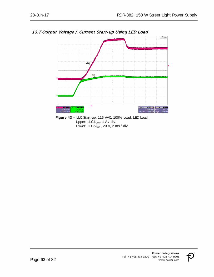
Upper: LLC IOUT, 1 A / div. Lower: LLC VOUT, 20 V, 2 ms / div.
RDR-382, 150 W Street Light Power Supply 28-Jun-17
Page 64 of 82
Power Integrations, Inc. Tel: +1 408 414 9200 Fax: +1 408 414 9201 www.power.com
13.8 LLC Output Short-Circuit The figure below shows the effect of an output short circuit on the LLC primary current and on the output current. A mercury displacement relay was used to short the output to get a fast, bounce-free connection.
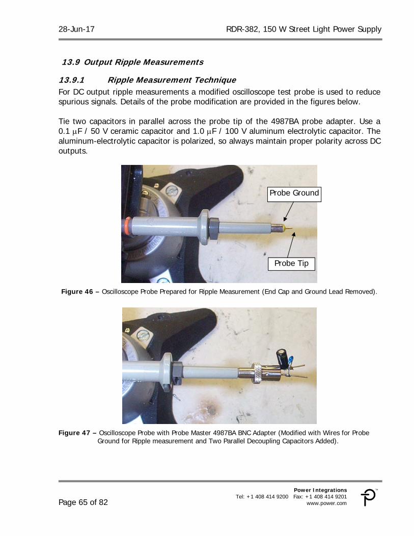
13.9.1 Ripple Measurement Technique For DC output ripple measurements a modified oscilloscope test probe is used to reduce spurious signals. Details of the probe modification are provided in the figures below. Tie two capacitors in parallel across the probe tip of the 4987BA probe adapter. Use a 0.1 F / 50 V ceramic capacitor and 1.0 F / 100 V aluminum electrolytic capacitor. The aluminum-electrolytic capacitor is polarized, so always maintain proper polarity across DC outputs.
Figure 46 – Oscilloscope Probe Prepared for Ripple Measurement (End Cap and Ground Lead Removed).
Figure 47 – Oscilloscope Probe with Probe Master 4987BA BNC Adapter (Modified with Wires for Probe
Ground for Ripple measurement and Two Parallel Decoupling Capacitors Added).
Probe Ground
Probe Tip
RDR-382, 150 W Street Light Power Supply 28-Jun-17
Page 66 of 82
Power Integrations, Inc. Tel: +1 408 414 9200 Fax: +1 408 414 9201 www.power.com
13.9.2 Ripple Measurements
Figure 48 – Output Ripple, Full Load, 115 VAC.
Upper: IOUT, 1 A / div. Lower: Output Voltage Ripple, 100 mV, 5 ms / div.
28-Jun-17 RDR-382, 150 W Street Light Power Supply
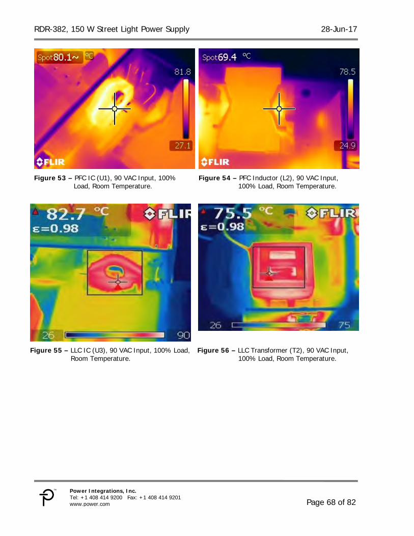
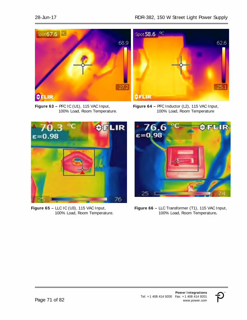
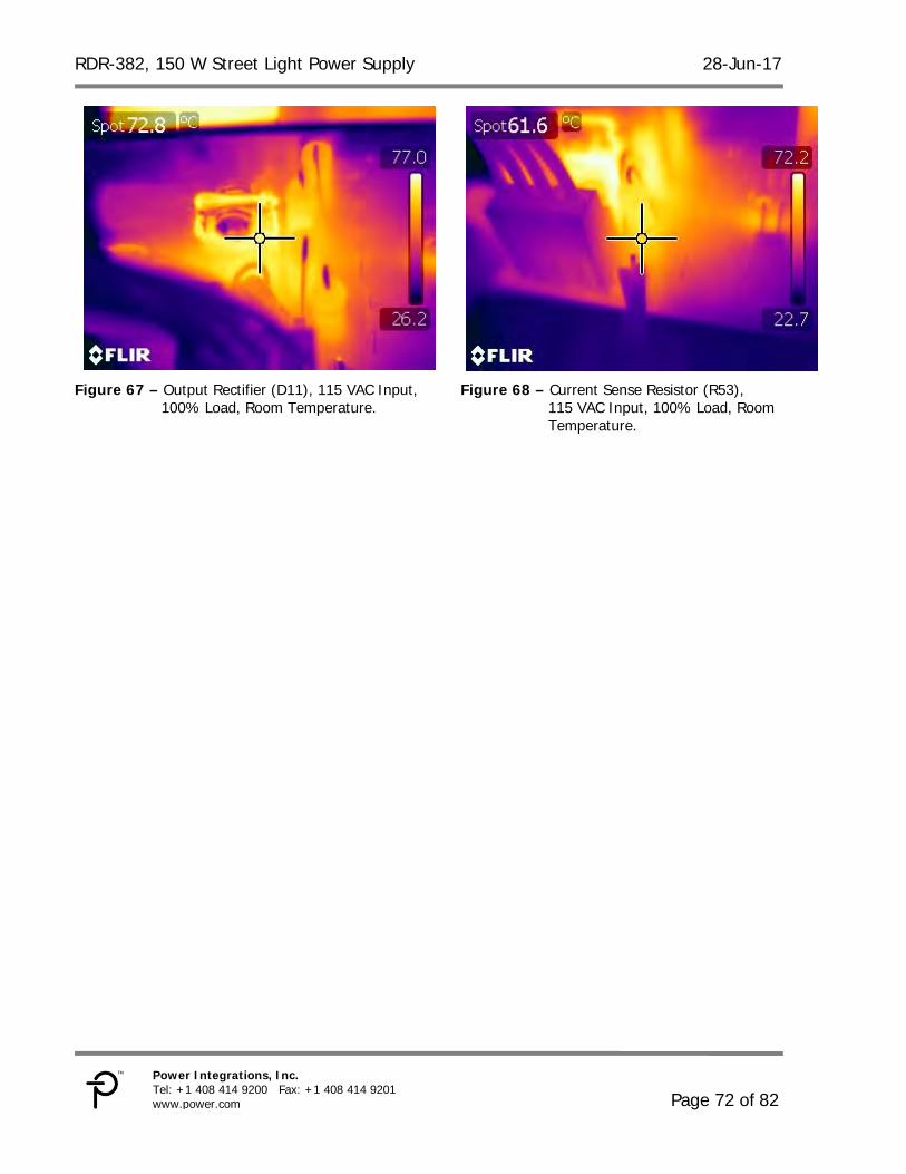
14 Temperature Profiles The board was operated at room temperature, with output set at maximum using a constant resistance load. For each test condition the unit was allowed to thermally stabilize (~1 hr) before measurements were made.
14.1 90 VAC, 60 Hz, 150 W Output, Room Temperature
100% Load, Room Temperature. Figure 78 – Current Sense Resistor (R53),
230 VAC Input, 100% Load, Room Temperature.
RDR-382, 150 W Street Light Power Supply 28-Jun-17
Page 76 of 82
Power Integrations, Inc. Tel: +1 408 414 9200 Fax: +1 408 414 9201 www.power.com
15 Output Gain-Phase Gain-phase was tested a maximum load using the constant voltage load described in Section 7.1. It is important to use the actual LED load or a load with similar characteristics during gain-phase testing, as a load with different output characteristic will yield inaccurate results.
16 Conducted EMI Conducted EMI tests were performed using the constant voltage load described in Section 7.1. The output return was connected to the LISN artificial hand to simulate the capacitance of a typical set of LED panels to chassis ground. The step change in readings at 80 MHz is due to an automatic 10 dB scale change of the EMI receiver rather than an actual peak at 80 MHz.
Figure 80 – Conducted EMI, 115 VAC, Full Load.
RDR-382, 150 W Street Light Power Supply 28-Jun-17
Page 78 of 82
Power Integrations, Inc. Tel: +1 408 414 9200 Fax: +1 408 414 9201 www.power.com
Figure 81 – Conducted EMI, 230 VAC, Full Load.
28-Jun-17 RDR-382, 150 W Street Light Power Supply
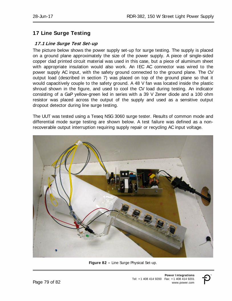
17.1 Line Surge Test Set-up The picture below shows the power supply set-up for surge testing. The supply is placed on a ground plane approximately the size of the power supply. A piece of single-sided copper clad printed circuit material was used in this case, but a piece of aluminum sheet with appropriate insulation would also work. An IEC AC connector was wired to the power supply AC input, with the safety ground connected to the ground plane. The CV output load (described in section 7) was placed on top of the ground plane so that it would capacitively couple to the safety ground. A 48 V fan was located inside the plastic shroud shown in the figure, and used to cool the CV load during testing. An indicator consisting of a GaP yellow-green led in series with a 39 V Zener diode and a 100 ohm resistor was placed across the output of the supply and used as a sensitive output dropout detector during line surge testing. The UUT was tested using a Teseq NSG 3060 surge tester. Results of common mode and differential mode surge testing are shown below. A test failure was defined as a non-recoverable output interruption requiring supply repair or recycling AC input voltage.
Figure 82 – Line Surge Physical Set-up.
RDR-382, 150 W Street Light Power Supply 28-Jun-17
Page 80 of 82
Power Integrations, Inc. Tel: +1 408 414 9200 Fax: +1 408 414 9201 www.power.com
17.2 Differential Mode Surge, 1.2 / 50 sec AC Input Voltage (VAC)
RDR-382, 150 W Street Light Power Supply 28-Jun-17
Page 82 of 82
Power Integrations, Inc. Tel: +1 408 414 9200 Fax: +1 408 414 9201 www.power.com
For the latest updates, visit our website: www.power.com Power Integrations reserves the right to make changes to its products at any time to improve reliability or manufacturability. Power Integrations does not assume any liability arising from the use of any device or circuit described herein. POWER INTEGRATIONS MAKES NO WARRANTY HEREIN AND SPECIFICALLY DISCLAIMS ALL WARRANTIES INCLUDING, WITHOUT LIMITATION, THE IMPLIED WARRANTIES OF MERCHANTABILITY, FITNESS FOR A PARTICULAR PURPOSE, AND NON-INFRINGEMENT OF THIRD PARTY RIGHTS.
JAPAN Kosei Dai-3 Building 2-12-11, Shin-Yokohama, Kohoku-ku, Yokohama-shi, Kanagawa 222-0033 Japan Phone: +81-45-471-1021 Fax: +81-45-471-3717 e-mail: [email protected]
TAIWAN 5F, No. 318, Nei Hu Rd., Sec. 1 Nei Hu District Taipei 11493, Taiwan R.O.C. Phone: +886-2-2659-4570 Fax: +886-2-2659-4550 e-mail: [email protected]
INDIA #1, 14th Main Road Vasanthanagar Bangalore-560052 India Phone: +91-80-4113-8020 Fax: +91-80-4113-8023 e-mail: [email protected]
KOREA RM 602, 6FL Korea City Air Terminal B/D, 159-6 Samsung-Dong, Kangnam-Gu, Seoul, 135-728 Korea Phone: +82-2-2016-6610 Fax: +82-2-2016-6630 e-mail: [email protected]
UK First Floor, Unit 15, Meadway Court, Rutherford Close, Stevenage, Herts. SG1 2EF United Kingdom Phone: +44 (0) 1252-730-141 Fax: +44 (0) 1252-727-689 e-mail: [email protected]