Reference Standard 5 81 REFERENCE STANDARD RS-5 FIRE PROTECTION CONSTRUCTION REQUIREMENTS * LIST OF REFERENCED NATIONAL STANDARDS AISG Fire Resistance Ratings, as Modified …………………………………………………………………1985 AISI FT-900-0480 Designing Fire Protection for Steel Columns, Third Edition ………………………………………... 1980 AISI FT-901-0481 Fire Resistant Rating of Load Bearing Steel Stud Walls ……………………………………………..1981 AISI FT-902-0285 Designing Fire Protection for Steel Beams .........……………….…………………………………… 1984 AISI FT-227-1281 Designing Fire Protection for Steel Trusses, Second Edition ………………………………………...1981 GA-600 Fire Resistance Design Manual, Twelfth Edition, as Modified……………………………………….1988 NFoPA Report No. WHI-694-020, Report of Testing on a Load Bearing Stud Partition …………………….1981 NFoPA Report No. WHI-690-003, Report of Testing on a Load-Bearing Stud Partition ...…………………..1981 ASTM/E 119 Standard Methods of Fire Tests of Building Construction and Materials .....……. ………………….1988 AWPA C 20 Structural Lumber-Fire Retardant Treatment by Pressure Processes ............. ………………………. 1988 AWPA C 27 Plywood Fire Retardant Treatment by Pressure Processes……………………………………………1988 ASTM E 84 Standard Method of Test for Surface Burning Characteristics of Building Materials ….…………… 1987 ANSI/ASTM E 69 Standard Test Method for Combustible Properties of Treated Wood by Fire-Tube Apparatus ……...1980 ANSI/ASTM E 160 Standard Test Method for Combustible Properties of Treated Wood by Crib Test ……………….… 1980 ANSI/ASTM E 152 Standard Methods of Fire Test of Door Assemblies ..........................………………………..……… 1981a ANSI/ASTM E 163 Standard Methods of Fire Test of Window Assemblies ..........………………………………………. 1984 NFiPA 80 Standard for Fire Doors and Windows ………….............................………………………………… 1986 ANSI/ASTM E 108 Standard Methods of Fire Test of Roof Coverings .........………………………………………….….1983 NFiPA 204M Guide for Smoke and Heat Venting ..............................………...…………………………………….1985 ANSI/ASTM D635 Standard Test for Rate of Burning and/or Extent and Time of Burning of Self-Supporting Plastics in a Horizontal Position ..........................……….………………………………………………………… 1981 ANSI/ASTM D568 Standard Test Method for Rate of Burning and/or Extent and Time of Burning of Flexible Plastics in a Vertical Position …..........…………………………………………………………………………… 1977 ANSI/ASTM D374 Standard Test Methods for Thickness of Solid Electrical Insulation ………………………………... 1979 ASTM E 814 Standard Method of Fire Tests of Through-Penetration Fire Stops ............................................……. 1983 DOC FF1 Methanine Pill Test …………………………………………………………………….......................1970 ASTM E 648 Standard Test Method for Critical Radiant Flux of Floor Covering Systems using a Radiant Heat Energy Source ......………............……………….……………………………………………………………1988 ASTM E 662 Standard Test Method for Specific Optical Density of Smoke Generated by Solid Materials .......…. 1983 ***UBC Std. 26-9 Method of Test for the Evaluation of Flammability Characteristics of Exterior, Nonload-Bearing Wall Containing Combustible Components Using the Intermediate Scale,Multistory Test Apparatus…….1997 *Local Law 13-1987; Local Law 16-1984; 242-90 BCR; 1343-88 BCR; 236-87 BCR; 1076-86 BCR; 262-86 BCR; 435-85 BCR; 252-82 BCR ***DOB 3-4-01 **REFERENCE STANDARD RS 5-1A AISG 1985-Fire Resistance Ratings, as modified. MODIFICATIONS-The provisions of the AISG Fire Resistance Ratings shall be subject to the following modifications: 1. Delete the following pages in their entirety: 22, 24, 45, 46***, 48, 52, 54, 76, 84, 97, 98, 99, 102, 110, 115, 117. 2. Delete the specified items on the following pages: PAGE DESCRIPTION-SPECIFIED ITEMS 25 Protection Type-Unprotected Rating(s) of 45 and 30 min. comb. 28 Protection Type-None Rating(s) of 45 min. comb. 29 2 1/2 slab thickness-Rating 30 min.
Transcript
Reference Standard 5
81
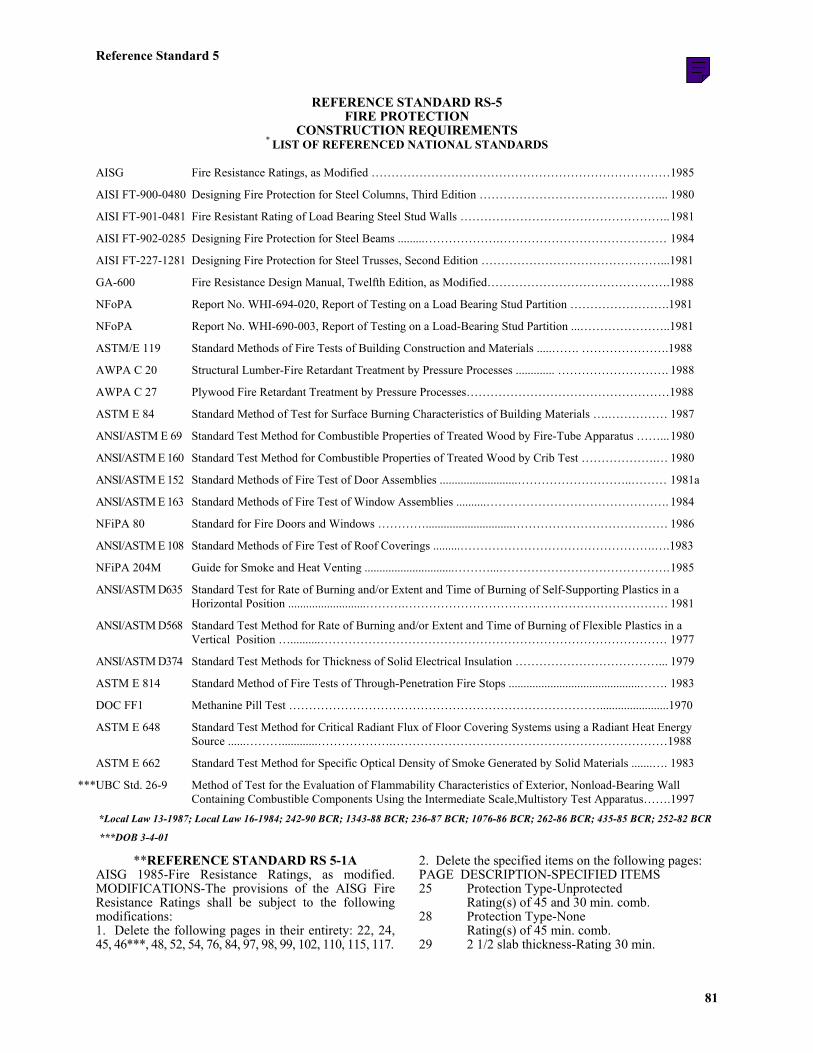
REFERENCE STANDARD RS-5FIRE PROTECTION
CONSTRUCTION REQUIREMENTS* LIST OF REFERENCED NATIONAL STANDARDS
AISG Fire Resistance Ratings, as Modified …………………………………………………………………1985
AISI FT-900-0480 Designing Fire Protection for Steel Columns, Third Edition ………………………………………... 1980
AISI FT-901-0481 Fire Resistant Rating of Load Bearing Steel Stud Walls ……………………………………………..1981
AISI FT-902-0285 Designing Fire Protection for Steel Beams .........……………….…………………………………… 1984
AISI FT-227-1281 Designing Fire Protection for Steel Trusses, Second Edition ………………………………………...1981
GA-600 Fire Resistance Design Manual, Twelfth Edition, as Modified……………………………………….1988
NFoPA Report No. WHI-694-020, Report of Testing on a Load Bearing Stud Partition …………………….1981
NFoPA Report No. WHI-690-003, Report of Testing on a Load-Bearing Stud Partition ...…………………..1981
ASTM/E 119 Standard Methods of Fire Tests of Building Construction and Materials .....……. ………………….1988
AWPA C 20 Structural Lumber-Fire Retardant Treatment by Pressure Processes ............. ………………………. 1988
AWPA C 27 Plywood Fire Retardant Treatment by Pressure Processes……………………………………………1988
ASTM E 84 Standard Method of Test for Surface Burning Characteristics of Building Materials ….…………… 1987
ANSI/ASTM E 69 Standard Test Method for Combustible Properties of Treated Wood by Fire-Tube Apparatus ……...1980
ANSI/ASTM E 160 Standard Test Method for Combustible Properties of Treated Wood by Crib Test ……………….… 1980
ANSI/ASTM E 152 Standard Methods of Fire Test of Door Assemblies ..........................………………………..……… 1981a
ANSI/ASTM E 163 Standard Methods of Fire Test of Window Assemblies ..........………………………………………. 1984
NFiPA 80 Standard for Fire Doors and Windows ………….............................………………………………… 1986
ANSI/ASTM E 108 Standard Methods of Fire Test of Roof Coverings .........………………………………………….….1983
NFiPA 204M Guide for Smoke and Heat Venting ..............................………...…………………………………….1985
ANSI/ASTM D635 Standard Test for Rate of Burning and/or Extent and Time of Burning of Self-Supporting Plastics in aHorizontal Position ..........................……….………………………………………………………… 1981
ANSI/ASTM D568 Standard Test Method for Rate of Burning and/or Extent and Time of Burning of Flexible Plastics in aVertical Position …..........…………………………………………………………………………… 1977
ANSI/ASTM D374 Standard Test Methods for Thickness of Solid Electrical Insulation ………………………………... 1979
ASTM E 814 Standard Method of Fire Tests of Through-Penetration Fire Stops ............................................……. 1983
DOC FF1 Methanine Pill Test …………………………………………………………………….......................1970
ASTM E 648 Standard Test Method for Critical Radiant Flux of Floor Covering Systems using a Radiant Heat EnergySource ......………............……………….……………………………………………………………1988
ASTM E 662 Standard Test Method for Specific Optical Density of Smoke Generated by Solid Materials .......…. 1983
***UBC Std. 26-9 Method of Test for the Evaluation of Flammability Characteristics of Exterior, Nonload-Bearing WallContaining Combustible Components Using the Intermediate Scale,Multistory Test Apparatus…….1997
*Local Law 13-1987; Local Law 16-1984; 242-90 BCR; 1343-88 BCR; 236-87 BCR; 1076-86 BCR; 262-86 BCR; 435-85 BCR; 252-82 BCR
***DOB 3-4-01
**REFERENCE STANDARD RS 5-1AAISG 1985-Fire Resistance Ratings, as modified.MODIFICATIONS-The provisions of the AISG FireResistance Ratings shall be subject to the followingmodifications:1. Delete the following pages in their entirety: 22, 24,45, 46***, 48, 52, 54, 76, 84, 97, 98, 99, 102, 110, 115, 117.
2. Delete the specified items on the following pages:PAGE DESCRIPTION-SPECIFIED ITEMS25 Protection Type-Unprotected
Rating(s) of 45 and 30 min. comb.28 Protection Type-None
Rating(s) of 45 min. comb.29 2 1/2 slab thickness-Rating 30 min.
Disclaimer
The Department of Buildings provides this Web version of the Building Code for reference and informational purposes only. The print version of the Building Code, together with any Local Laws (amendments) adopted by the City Council subsequent to the most recent update to the print version, remains the official version. For those discrepancies that exist between the print and Web versions of the Building Code, the print version, together with any City Council amendments, shall be considered correct. This web version may also include amendments that are not yet on the printed version.
Rating of 30 min. comb.48 Ceiling Type-Gypsum Wallboard Rating of 25
min. comb.50 Ceiling Type-Plaster on Gypsum Lath
Rating(s) of 45 min. and 30 min. comb.62 Type-Calcareous Gravel
Rating(s) 30 min. and 20 min. comb.63 Type-Cinder Rating 45 min.65 Type-Expanded clay, shale or slate (Rotary
kiln) Rating 45 min.68 Type-Siliceous Gravel
Rating(s) 20 min. and 15 min.77 Plaster Type-Gypsum Neat Rating 45 min.83 Plaster Type-Gypsum and Sand Rating 45 min.91 Plaster Type-Portland Cement and Sand
Rating(s) 45 min. and 30 min.95 Type-Clay or Shale Rating 45 min.103 Finish Type-Laminated Wood Rating(s) 45 min.,
30 min., 25 min., 15 min. and 10 min. comb.104 Finish Type-Asbestos Cement Board
Rating(s) 40 min. and 30 min. comb.107 Plaster Type (4)-Gypsum and Sand
Rating(s) 45 min. and 30 min. comb.109 Plaster Type (5)-Gypsum and Sand
Rating(s) 45 min., 30 min. and 20 min. comb.111 Plaster Type-Gypsum and Sand Rating 30
min. comb. Lime and Sand Rating(s) 45 min.,30 min. and 25 min. comb.
112 Finish Type-Asbestos Cement BoardRating(s) 30 min. and 10 min. comb.
114 Finish Type-Gypsum WallboardRating(s) 45 min., 30 min., and 25 min. comb.
117 Finish Type-Wood Rating 45 min. comb.3. An equivalent blend of mineral fibers andcementitious binders may be substituted for asbestos-cement material on the following pages: 46, 51, 52, 92,104, 112, 114.**
1076-86 BCR***
As enacted, but “46” probably intended to be omitted.
* REFERENCE STANDARD RS 5-1BGA-600 1988-Fire Resistance Design Manual, TwelfthEdition, as Modified.MODIFICATIONS.-The provisions of GA-600-1988shall be subject to the following modifications:1. Revise the heading on the top of page five in thesection on USE OF MANUAL to read as follows:
LIMITING HEIGHTS(a) NONLOAD-BEARING PARTITIONS2. Insert the following after the paragraphs on (a)NONLOAD-BEARING PARTITIONS and before theheading PERFORMANCE OF PLASTER:(b) LOAD BEARING PARTITIONSLateral bracing and height limitations shall be designedin accordance with the applicable reference standardindependent of the sheathing.
3. In the section on GENERAL EXPLANATORYNOTES under the heading USE OF MANUAL, add thefollowing paragraph:15. All concrete slabs shall be structurally adequate.Such slabs shall have a minimum compressive strengthof 3000 psi., with the reinforcement and thickness atleast that as shown in the test.4. In the assemblies listed under the heading WALLSAND INTERIOR PARTITIONS, NONCOMBUSTIBLE,the following requirements are added to the DetailedDescription for (LOAD BEARING) assemblies:WP 1204, WP 1206, WP 1635, WP 1714 and WP 1716under the GA and Company Codes:Steel Studs.-Steel studs shall be a minimum of 3 1/2inches wide and a minimum galvanized steel or 18 GA(.0478) or heavier, primed steel, cold-formed, and shallcomply with Reference Standard RS 10-6 (Specificationfor the Design of Cold-Formed Steel Structuralmembers by AISI, as modified). Lateral supportingmembers and all details enhancing the structuralintegrity of the wall assembly shall be as specified bythe steel stud designer, and shall meet the applicablerequirements of the Code.5. In the assemblies listed under METAL CLADEXTERIOR WALLS, assemblies WP 9010, WP 9060,WP 9225, WP 9325, under the GA File No. heading,are deleted in its entirety.6. Insert the following heading after the paragraph onUSE OF PLENUM SPACE in the section on FLOOR-CEILINGS:
SUSPENSION SYSTEMSSuspended ceilings contained herein shall comply withthe requirements of Reference Standard RS 5-16.7. In the assemblies listed under FLOOR-CEILINGASSEMBLIES, NON-COMBUSTIBLE, assembly FC4120, under the GA File No. heading, is deleted in itsentirety.8. In the assemblies listed under FLOOR-CEILINGASSEMBLIES, WOOD-FRAMED, assembly FC 5105,under the GA File No. heading, is deleted in theirentirety.9. In the assemblies listed under BEAMS, GIRDERS,AND TRUSSES, assemblies BM 3310, BM 4410 andBM 4420, under the GA File No. heading, are deletedin their entirety.10. The following assemblies which were listed in theGypsum Association Fire Resistance Manual, EleventhEdition, but do not appear in the Twelfth Edition, maycontinue to be used:
** REFERENCE STANDARD RS 5-1C MISCELLANEOUS TEST REPORTS
FOR LOAD-BEARING WALL ASSEMBLIES NON-COMBUSTIBLE: ONE, ONE AND ONE-
HALF, AND TWO-HOUR FIRE RATINGS.
AISI FT-901-0481-1981- Fire Resistance of Load-Bearing Steel Stud Walls with Gypsum Wallboard Protection with or without Cavity Insulation. MODIFICATIONS: The provisions of AISI FT-901-1981, are modified as follows: 1. Delete all Fire Resistive Assemblies with 45 minute ratings. 2. Substitute the following for paragraph 2: Steel Studs-Corrosion-Protected steel studs, min. 3 1/2 inches wide, min. No. 18 GSG (0.047 inch thick) galvanized steel or No. 18 MSG (0.043 inch thick) primed steel, cold-formed, shall be designed in accordance with Reference Standard RS 10-6 (Specification for the Design of Cold-Formed Steel Structural members by AISI, as modified). All design details enhancing the structural integrity of the wall assembly including the axial design load of the studs, shall be as specified by the steel stud designer and/or the producer, and shall meet all applicable requirements of the code. The maximum stud spacing of wall assemblies shall not exceed 24 inches. Studs shall be attached to floor and ceiling tracks with 1/2 inch long Type S-12 pan head, self-drilling, self-tapping steel screws on both sides of the studs, or welded in accordance with RS 10-6. 3. Substitute the following for paragraph 3: Lateral Supporting Members (not shown)-Lateral support or bracing shall be provided in accordance with Reference Standard RS 10-6 independent sheathing. 4. Substitute the following for paragraph 4: Wallboard, Gypsum-Gypsum wallboard shall conform to ASTM C 36 Type X and be identified as such. The wallboard shall be applied vertically with joints between layers staggered. Outer layer of three-layer construction may be applied horizontally. The thickness and number of layers and percent of design load for the 1 hour, 1 1/2 hour and 2 hour ratings shall be as specified in the table above. 5. Substitute the following for paragraph 7: Batts and Blankets-All insulation and noise control materials included in wall assemblies shall be Approved by the Board of Standards and Appeals or Accepted by the Materials and Equipment Acceptance Division of the Department of Buildings for the intended use. **252-82 BCR
UL FIRE RESISTANCE DIRECTORY Design U 425
Interior Walls-Wallboard Protection Both Sides of Wall
Rating
Number of Layers and Thickness of Boards in Each Layer
Percent of Design Load
1 hr. 1 layer, 5/8 in. thick 100 1 1/2 hr. 2 layers, 1/2 in. thick 100 2 hr. 2 layers, 5/8 in. thick or 80 *3 layers, 1/2 in. thick 100
*Ratings applicable to assemblies serving as exterior walls where Classified fire resistive gypsum sheathing type wallboard is substituted on the exterior face.
*Bearing the UL Classification Marking. Exterior Walls-Wallboard Protection on Interior
Side of Wall
Rating
Number of Layers and Thickness of Boards in Each Layer
Percent of Design Load
1 hr. 2 layer, 1/2 in. thick 100 1 1/2 hr. 2 layers, 5/8 in. thick 100 2 hr 3 layers, 1/2 in. thick 100
6. Steel Floor and Ceiling Tracks-Top and bottom
tracks of wall assemblies shall consist of steel members, min. No. 20 GSG (0.036 in. thick) galv. steel or No. 20 MSG (0.033 in.) thick primed steel, that provide a sound structural connection between steel studs and to adjacent assemblies such as a floor, ceiling and or other walls. Attached to floor and ceiling, assemblies with steel fasteners spaced not greater than 24 in.
7. Fasteners-Screws used to attach wallboard to studs: self-tapping bugle head sheet steel type, spaced 12 in. o.c. First layer Type S-12 by 1 in. long; second layer Type S-12 by 1 3/8 in. long: third layer Type S-12 by 1 7/8 in. long.
8. Joint Tape and Compound-Vinyl or casein, dry or premixed joint compound applied in two coats to joints and screwheads of outer layer. Perforated paper tape, 2
in. wide, embedded in first layer of compound over all joints of outer layer. Report of Testing on a Load-Bearing Wood Stud Partition -Dated - October 19, 1981 Wall is constructed using 2 in. x 4 in. (nominal) wood studs spaced 16 in. on center. Fire exposed (interior) side is covered with 5/8 in. Type X Gypsum Wallboard applied vertically and fastened with 6d box nails on 7
83 revision: July 1, 2008
Reference Standard 5
in. centers. Unexposed side (exterior) is faced with a layer of 1/2 in. thick Fiberboard Sheathing (0.835 psf) applied vertically and fastened with 1 1/2 in. roofing nails on 3 in. centers at edges and 6 in. centers at intermediate supports. Hardboard Shiplap Edge Panel Siding, 3/8 in. thick (1.84 psf) is applied vertically over the Fiberboard Sheathing and fastened with 8d nails on 4 in. centers at edges and 8 in. centers at intermediate supports. The Cavity Spaces (stud spaces) are filled with Mineral Wool Batts having a density of 2.14 lbs./cu ft. (Mineral wool may be rock wool or slag wool of equivalent density.) All insulation and noise control materials included in wall assemblies shall be Approved by the Board of Standards and Appeals or Accepted by the Material and Equipment Acceptance Division of the Department of Buildings for the intended use. The maximum load permissible on the studs in this assembly shall be 2000 lbs. each.
Report of Testing on a Load-Bearing Wood Stud Partition - Dated - October 9, 1981 Wall is constructed using 2 in. x 4 in. (nominal) wood
studs spaced 16 in. on centers. Fire exposed side (interior) is covered with 5/8 in. Type X Gypsum Wallboard applied vertically and fastened with 6d box nails on 7 in. centers. Unexposed side (exterior) is faced with 3/8 in. thick (5/8 in. between grooves) exterior grade plywood panels applied vertically and fastened with 8d nails on 6 in. centers around edges and 12 in. centers at intermediate supports. The Cavity (stud) Spaces are filled with Mineral Wool Batts having a density of 2 lbs./cu. ft. (Mineral wool may be rock wool or slag wool of equivalent density.) All insulation and noise control materials included in wall assemblies shall be Approved by the Board of Standards and Appeals or Accepted by the Material and Equipment Acceptance Division of the Department of Buildings for the intended use. The maximum load permissible on the studs in this assembly shall be 2000 lbs. each. * REFERENCE STANDARD 5-1D MISCELLANEOUS TEST REPORTS FOR LOAD BEARING STEEL COLUMN ASSEMBLIES NONCOMBUSTIBLE: DESIGN OF ONE, ONE AND ONE-HALF, TWO, THREE AND FOUR HOUR FIRE RATINGS OF PROTECTED COLUMNS AISI FT-900-0480-1980 Designing Fire Protection for Steel Columns, third edition. MODIFICATIONS: The provisions of AISI FT-900-0480-1980 are modified as follows: 1. In Part I-Fire Resistance Ratings for Columns Protected with Gypsum Wallboard values determined by formula shall govern when interpolating graphical or tabular results. 2. In Part I-Fire Resistance Ratings for Columns Protected with Gypsum Wallboard, all reference to approved gypsum wallboard shall infer material conforming to ASTM C36 Type X and be identified as such. All gypsum wallboard used in fire resistive steel column assemblies designed in accordance with this Reference Standard shall be installed in accordance with one of the methods recommended in this reference standard. 3. Constants C1 and C2 shall be applicable only to the materials identified in Section C of Part II-Calculating Fire Resistance Ratings for Columns Protected with Spray-Applied Materials. Constants for other spray-applied fire proofing materials shall be determined by ASTM E 119 fire tests. The tests and their evaluation shall be submitted to the Material and Acceptance Division (MEA) for acceptance. 4. The formulas for determining thickness of fire protection materials shall not be used with columns or built-up sections that have W/D ratios larger than those of the W14x233 shape. Fire protection thickness may be applied to columns larger than the W14x233 provided the thickness of fire protection materials to be applied to columns are the same as those required for the W14x233 column. 5. In absence of substantiating fire endurance test results, ducts, conduit, piping and similar mechanical, electrical and plumbing installations shall not be
84
Reference Standard 5
85
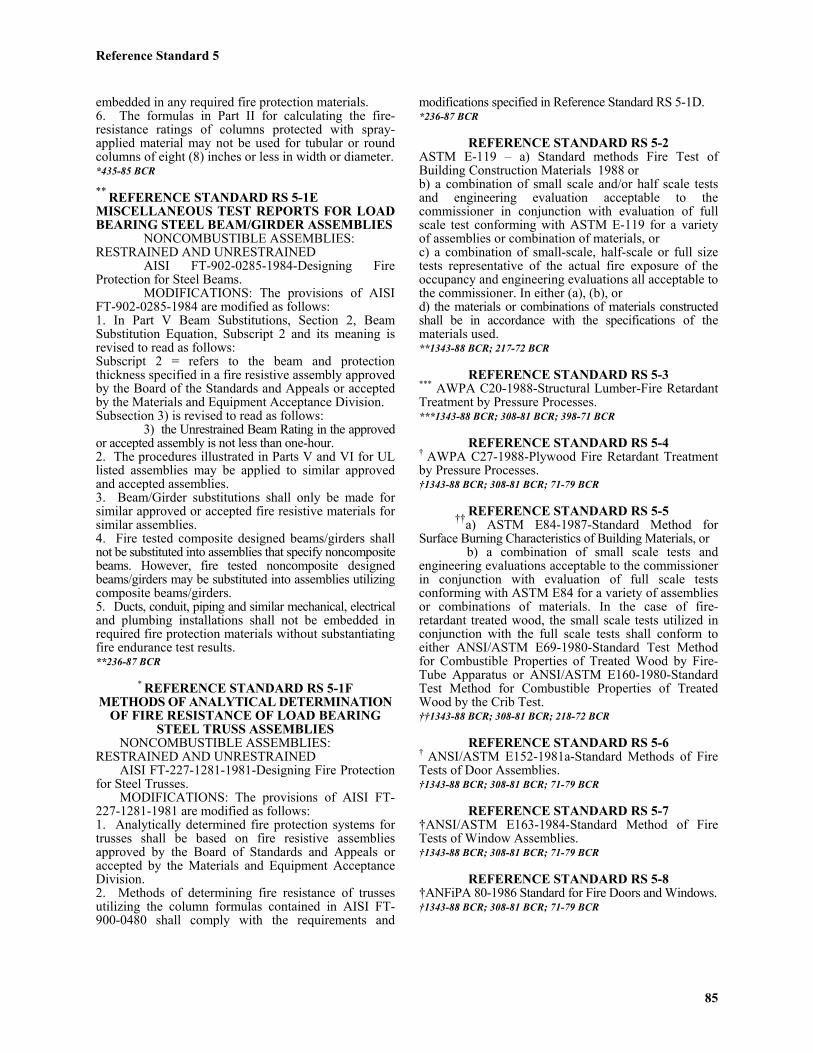
embedded in any required fire protection materials.6. The formulas in Part II for calculating the fire-resistance ratings of columns protected with spray-applied material may not be used for tubular or roundcolumns of eight (8) inches or less in width or diameter.*435-85 BCR
** REFERENCE STANDARD RS 5-1EMISCELLANEOUS TEST REPORTS FOR LOADBEARING STEEL BEAM/GIRDER ASSEMBLIES
NONCOMBUSTIBLE ASSEMBLIES:RESTRAINED AND UNRESTRAINED
AISI FT-902-0285-1984-Designing FireProtection for Steel Beams.
MODIFICATIONS: The provisions of AISIFT-902-0285-1984 are modified as follows:1. In Part V Beam Substitutions, Section 2, BeamSubstitution Equation, Subscript 2 and its meaning isrevised to read as follows:Subscript 2 = refers to the beam and protectionthickness specified in a fire resistive assembly approvedby the Board of the Standards and Appeals or acceptedby the Materials and Equipment Acceptance Division.Subsection 3) is revised to read as follows:
3) the Unrestrained Beam Rating in the approvedor accepted assembly is not less than one-hour.2. The procedures illustrated in Parts V and VI for ULlisted assemblies may be applied to similar approvedand accepted assemblies.3. Beam/Girder substitutions shall only be made forsimilar approved or accepted fire resistive materials forsimilar assemblies.4. Fire tested composite designed beams/girders shallnot be substituted into assemblies that specify noncompositebeams. However, fire tested noncomposite designedbeams/girders may be substituted into assemblies utilizingcomposite beams/girders.5. Ducts, conduit, piping and similar mechanical, electricaland plumbing installations shall not be embedded inrequired fire protection materials without substantiatingfire endurance test results.**236-87 BCR
* REFERENCE STANDARD RS 5-1FMETHODS OF ANALYTICAL DETERMINATION
OF FIRE RESISTANCE OF LOAD BEARINGSTEEL TRUSS ASSEMBLIES
NONCOMBUSTIBLE ASSEMBLIES:RESTRAINED AND UNRESTRAINED
AISI FT-227-1281-1981-Designing Fire Protectionfor Steel Trusses.
MODIFICATIONS: The provisions of AISI FT-227-1281-1981 are modified as follows:1. Analytically determined fire protection systems fortrusses shall be based on fire resistive assembliesapproved by the Board of Standards and Appeals oraccepted by the Materials and Equipment AcceptanceDivision.2. Methods of determining fire resistance of trussesutilizing the column formulas contained in AISI FT-900-0480 shall comply with the requirements and
modifications specified in Reference Standard RS 5-1D.*236-87 BCR
REFERENCE STANDARD RS 5-2ASTM E-119 – a) Standard methods Fire Test ofBuilding Construction Materials 1988 orb) a combination of small scale and/or half scale testsand engineering evaluation acceptable to thecommissioner in conjunction with evaluation of fullscale test conforming with ASTM E-119 for a varietyof assemblies or combination of materials, orc) a combination of small-scale, half-scale or full sizetests representative of the actual fire exposure of theoccupancy and engineering evaluations all acceptable tothe commissioner. In either (a), (b), ord) the materials or combinations of materials constructedshall be in accordance with the specifications of thematerials used.**1343-88 BCR; 217-72 BCR
REFERENCE STANDARD RS 5-3*** AWPA C20-1988-Structural Lumber-Fire RetardantTreatment by Pressure Processes.***1343-88 BCR; 308-81 BCR; 398-71 BCR
REFERENCE STANDARD RS 5-4† AWPA C27-1988-Plywood Fire Retardant Treatmentby Pressure Processes.†1343-88 BCR; 308-81 BCR; 71-79 BCR
REFERENCE STANDARD RS 5-5††a) ASTM E84-1987-Standard Method forSurface Burning Characteristics of Building Materials, or
b) a combination of small scale tests andengineering evaluations acceptable to the commissionerin conjunction with evaluation of full scale testsconforming with ASTM E84 for a variety of assembliesor combinations of materials. In the case of fire-retardant treated wood, the small scale tests utilized inconjunction with the full scale tests shall conform toeither ANSI/ASTM E69-1980-Standard Test Methodfor Combustible Properties of Treated Wood by Fire-Tube Apparatus or ANSI/ASTM E160-1980-StandardTest Method for Combustible Properties of TreatedWood by the Crib Test.††1343-88 BCR; 308-81 BCR; 218-72 BCR
REFERENCE STANDARD RS 5-6† ANSI/ASTM E152-1981a-Standard Methods of FireTests of Door Assemblies.†1343-88 BCR; 308-81 BCR; 71-79 BCR
REFERENCE STANDARD RS 5-7†ANSI/ASTM E163-1984-Standard Method of FireTests of Window Assemblies.†1343-88 BCR; 308-81 BCR; 71-79 BCR
REFERENCE STANDARD RS 5-8†ANFiPA 80-1986 Standard for Fire Doors and Windows.†1343-88 BCR; 308-81 BCR; 71-79 BCR
Reference Standard 5
86
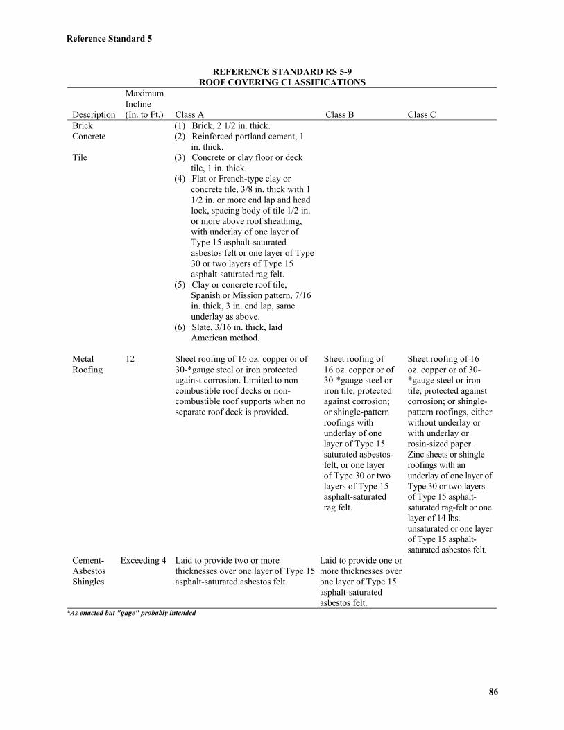
REFERENCE STANDARD RS 5-9ROOF COVERING CLASSIFICATIONS
Description
MaximumIncline(In. to Ft.) Class A Class B Class C
BrickConcrete
Tile
(1) Brick, 2 1/2 in. thick.(2) Reinforced portland cement, 1
in. thick.(3) Concrete or clay floor or deck
tile, 1 in. thick.(4) Flat or French-type clay or
concrete tile, 3/8 in. thick with 11/2 in. or more end lap and headlock, spacing body of tile 1/2 in.or more above roof sheathing,with underlay of one layer ofType 15 asphalt-saturatedasbestos felt or one layer of Type30 or two layers of Type 15asphalt-saturated rag felt.
(5) Clay or concrete roof tile,Spanish or Mission pattern, 7/16in. thick, 3 in. end lap, sameunderlay as above.
(6) Slate, 3/16 in. thick, laidAmerican method.
MetalRoofing
12 Sheet roofing of 16 oz. copper or of30-*gauge steel or iron protectedagainst corrosion. Limited to non-combustible roof decks or non-combustible roof supports when noseparate roof deck is provided.
Sheet roofing of16 oz. copper or of30-*gauge steel oriron tile, protectedagainst corrosion;or shingle-patternroofings withunderlay of onelayer of Type 15saturated asbestos-felt, or one layerof Type 30 or twolayers of Type 15asphalt-saturatedrag felt.
Sheet roofing of 16oz. copper or of 30-*gauge steel or irontile, protected againstcorrosion; or shingle-pattern roofings, eitherwithout underlay orwith underlay orrosin-sized paper.Zinc sheets or shingleroofings with anunderlay of one layer ofType 30 or two layersof Type 15 asphalt-saturated rag-felt or onelayer of 14 lbs.unsaturated or one layerof Type 15 asphalt-saturated asbestos felt.
Cement-AsbestosShingles
Exceeding 4 Laid to provide two or morethicknesses over one layer of Type 15asphalt-saturated asbestos felt.
Laid to provide one ormore thicknesses overone layer of Type 15asphalt-saturatedasbestos felt.
*As enacted but "gage" probably intended
Reference Standard 5
87
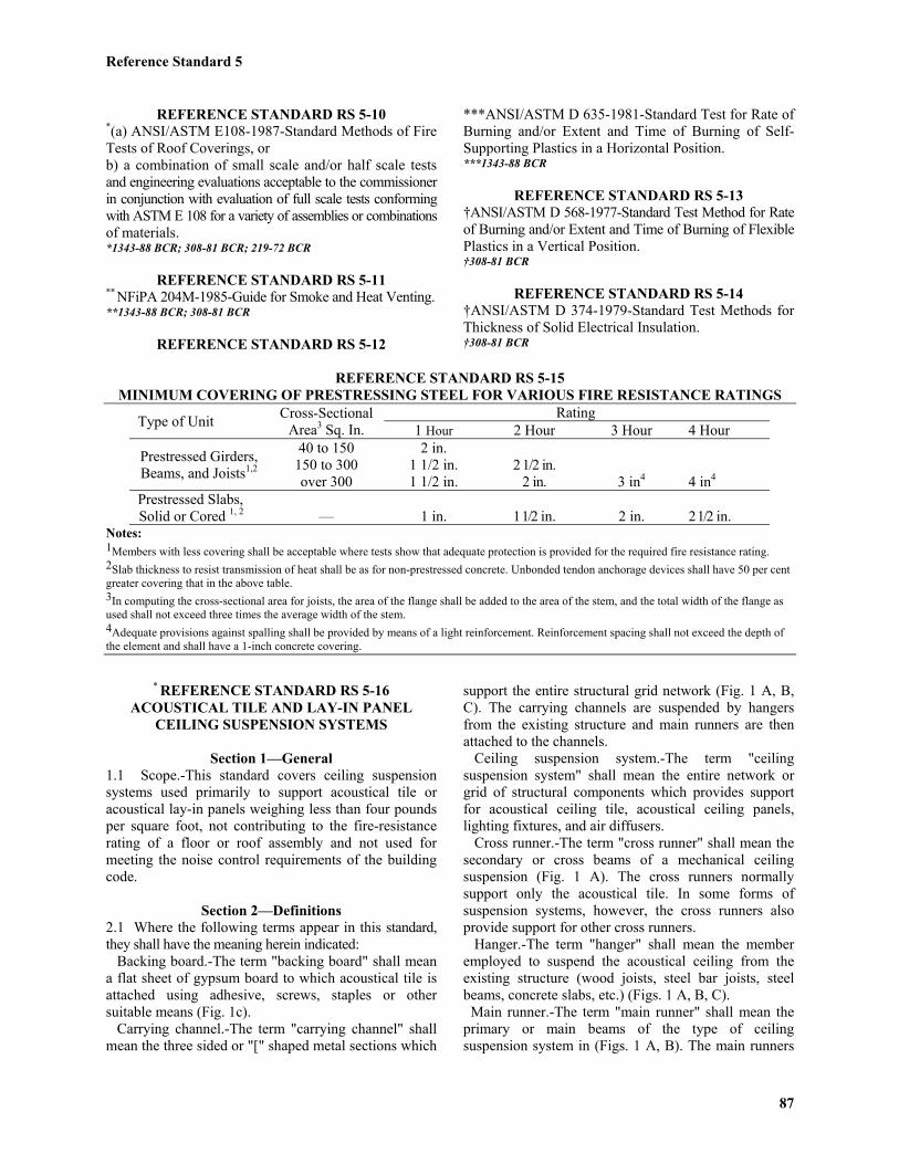
REFERENCE STANDARD RS 5-10*(a) ANSI/ASTM E108-1987-Standard Methods of FireTests of Roof Coverings, orb) a combination of small scale and/or half scale testsand engineering evaluations acceptable to the commissionerin conjunction with evaluation of full scale tests conformingwith ASTM E 108 for a variety of assemblies or combinationsof materials.*1343-88 BCR; 308-81 BCR; 219-72 BCR
REFERENCE STANDARD RS 5-11** NFiPA 204M-1985-Guide for Smoke and Heat Venting.**1343-88 BCR; 308-81 BCR
REFERENCE STANDARD RS 5-12
***ANSI/ASTM D 635-1981-Standard Test for Rate ofBurning and/or Extent and Time of Burning of Self-Supporting Plastics in a Horizontal Position.***1343-88 BCR
REFERENCE STANDARD RS 5-13†ANSI/ASTM D 568-1977-Standard Test Method for Rateof Burning and/or Extent and Time of Burning of FlexiblePlastics in a Vertical Position.†308-81 BCR
REFERENCE STANDARD RS 5-14†ANSI/ASTM D 374-1979-Standard Test Methods forThickness of Solid Electrical Insulation.†308-81 BCR
REFERENCE STANDARD RS 5-15MINIMUM COVERING OF PRESTRESSING STEEL FOR VARIOUS FIRE RESISTANCE RATINGS
RatingType of Unit Cross-SectionalArea3 Sq. In. 1 Hour 2 Hour 3 Hour 4 Hour
Prestressed Girders,Beams, and Joists1,2
40 to 150150 to 300over 300
2 in.1 1/2 in.1 1/2 in.
2 1/2 in.2 in. 3 in4 4 in4
Prestressed Slabs,Solid or Cored 1, 2 — 1 in. 1 1/2 in. 2 in. 2 1/2 in.
Notes:1Members with less covering shall be acceptable where tests show that adequate protection is provided for the required fire resistance rating.2Slab thickness to resist transmission of heat shall be as for non-prestressed concrete. Unbonded tendon anchorage devices shall have 50 per centgreater covering that in the above table.3In computing the cross-sectional area for joists, the area of the flange shall be added to the area of the stem, and the total width of the flange asused shall not exceed three times the average width of the stem.4Adequate provisions against spalling shall be provided by means of a light reinforcement. Reinforcement spacing shall not exceed the depth ofthe element and shall have a 1-inch concrete covering.
* REFERENCE STANDARD RS 5-16ACOUSTICAL TILE AND LAY-IN PANEL
CEILING SUSPENSION SYSTEMS
Section 1—General1.1 Scope.-This standard covers ceiling suspensionsystems used primarily to support acoustical tile oracoustical lay-in panels weighing less than four poundsper square foot, not contributing to the fire-resistancerating of a floor or roof assembly and not used formeeting the noise control requirements of the buildingcode.
Section 2—Definitions2.1 Where the following terms appear in this standard,they shall have the meaning herein indicated: Backing board.-The term "backing board" shall meana flat sheet of gypsum board to which acoustical tile isattached using adhesive, screws, staples or othersuitable means (Fig. 1c). Carrying channel.-The term "carrying channel" shallmean the three sided or "[" shaped metal sections which
support the entire structural grid network (Fig. 1 A, B,C). The carrying channels are suspended by hangersfrom the existing structure and main runners are thenattached to the channels. Ceiling suspension system.-The term "ceilingsuspension system" shall mean the entire network orgrid of structural components which provides supportfor acoustical ceiling tile, acoustical ceiling panels,lighting fixtures, and air diffusers. Cross runner.-The term "cross runner" shall mean thesecondary or cross beams of a mechanical ceilingsuspension (Fig. 1 A). The cross runners normallysupport only the acoustical tile. In some forms ofsuspension systems, however, the cross runners alsoprovide support for other cross runners. Hanger.-The term "hanger" shall mean the memberemployed to suspend the acoustical ceiling from theexisting structure (wood joists, steel bar joists, steelbeams, concrete slabs, etc.) (Figs. 1 A, B, C). Main runner.-The term "main runner" shall mean theprimary or main beams of the type of ceilingsuspension system in (Figs. 1 A, B). The main runners
Reference Standard 5
88
provide direct support for cross runners, and they maysupport lighting fixtures and air diffusers. In addition,the acoustical tile may also be directly supported by themain runners.Nailing bar.-The term "nailing bar" or "furring bar"shall mean the continuous sheet metal strips to which abacking board is attached using either nails or screws(Fig. 1 C). The nailing bars are installed perpendicularto and supported by the carrying channels. Spline.-The term "spline" shall mean a strip of sheetmetal or fiber inserted in the kerfs of adjacentacoustical tile to form a concealed mechanical joint seal(Fig 1 B). Wall molding.-The term "wall molding" shall meanthe edge angles or channels of a mechanical ceilingsuspension system which are attached to a wall (Figs. 1A, B). The wall molding provides support for acousticaltile, and cross runners which are located at the peripheryof the ceiling.
Section 3—Design3.1 The provisions of the building code for stresses
shall apply.3.2 The hangers shall be spaced at 4'-6" or less on
centers. Each hanger shall be capable of carrying allloads suspended therefrom plus an additional 200pounds located at midspan. The midspan deflection asattested in accordance with the test method described inSection 6 of this standard or as calculated shall notexceed 1/360 of the span. The connections of thecarrying channel to the hangers shall be adequate forthe load supported by the carrying channel plus 200pounds.
3.4 The main runner or nailing bar shall be capableof carrying all loads suspended therefrom. The midspandeflection as tested in accordance with the test methoddescribed in Section 6 of this standard or as calculatedshall not exceed 1/360 of the span. Each connection ofthe main runner or nailing bar to the carrying channelsshall be adequate for the load supported by the mainrunner plus two hundred (200) pounds.*
353-72BCR
3.5 Cross runners shall be capable of carrying allloads suspended therefrom. The midspan deflection astested in accordance with the test method described inSection 6 of this standard or as calculated shall notexceed 1/360 of the span.
3.6 Splines shall not be considered as providingnor shall be used for providing structural support for theceiling material.
3.7 All connection devices other than bolts shallbe approved by the Board of Standards and Appeals.However, they may be accepted under the code testmethod when test results indicating a factor of safety offour are filed in accordance with the provisions of
which oxidize or corrode when exposed to normal useenvironments shall be provided with protective coatings.
4.1.1 Sheet steel.-Components fabricated from sheetsteel shall be given an electro-galvanized, hot dippedgalvanized cadmium coating, or zinc coating.
4.1.2 Aluminum alloy.-Components fabricatedfrom aluminum alloys shall be anodized when exposedto a corrosive atmosphere.
Section 5—Installation5.1 Installation of components.-The components
of acoustical ceiling suspension systems shall beinstalled in accordance with the following requirementsand Figures 2A and 2B.
5.1.1 Hangers5.1.1.1 Buildings of construction group I.-For
requirements see Figs. 2A and 2B.5.1.1.2 Buildings of construction group II.-Every
other hanger supported from wood members shall be
Reference Standard 5
89
attached by two 1/4" diameter through bolts or clinchednails. The remaining hangers shall be attached asdescribed above or by two 1/4" diameter barbed anchornails 2 1/4" long with oval heads. All bolts and nailsshall be at least 2 in. above the bottom of the woodmembers.
5.1.1.3 Spacing.-Hangers for carrying channels shall bespaced at most 4'-6" on centers.5.1.1.4 Minimum sizes and quality.-Hangers forsuspending carrying channels shall be a minimum of1/4" diameter galvanized steel rods or flat bars at least1" x 1/8".5.1.1.5 Use of existing hangers.-Existing hangers maynot be used unless they comply, or are made to comply,with all the above provisions relating to hangers.
shall be installed so that they are level within 1/8 in. in
12 ft. leveling shall be performed with the supportinghangers taut. Local kinks or bends shall not be made inhangers as a means of leveling the carrying channels.
5.1.2.2 Attachment to hangers.-Carrying channelsshall be attached to the hangers in a manner that willprevent any vertical movement or rotation.
(See Figure 2-A and 2-B)
5.1.3 Main runners5.1.3.1 Leveling requirements.- Main runners shall
be installed so that they are all level within 1/8 in. in 12ft. Leveling shall be performed with the main runner infirm contact with the carrying channel.
5.1.3.2 Attachment to carrying channels.- Main runnersshall be attached to the carrying channels in a mannerthat will prevent any vertical movement or rotation.
*353-72 BCR
*353-72 BCR
Reference Standard 5
90
5.2 New suspended ceilings below existing suspendedceilings
5.2.1 Buildings of construction group 1.-Inbuildings of construction group 1 not more than oneexisting suspended ceiling may be retained above thenew suspended ceiling. All other existing ceilings mustbe removed. Where an existing ceiling is retained, thenew main runners shall be supported directly from thecarrying channels adjacent to the hangers.
5.2.2 Buildings of construction group II.-In buildings ofconstruction group II, all existing suspended ceilings shallbe removed prior to installation of new suspended ceiling.
5.2.3 Existing hangers.-Existing hangers shall notbe used for new suspended ceilings unless found to bein sound structural condition and comply with all therequirements of this standard relating to hangers.
5.3 Ceiling fixtures5.3.1 General.-Fixtures installed in acoustical tile or
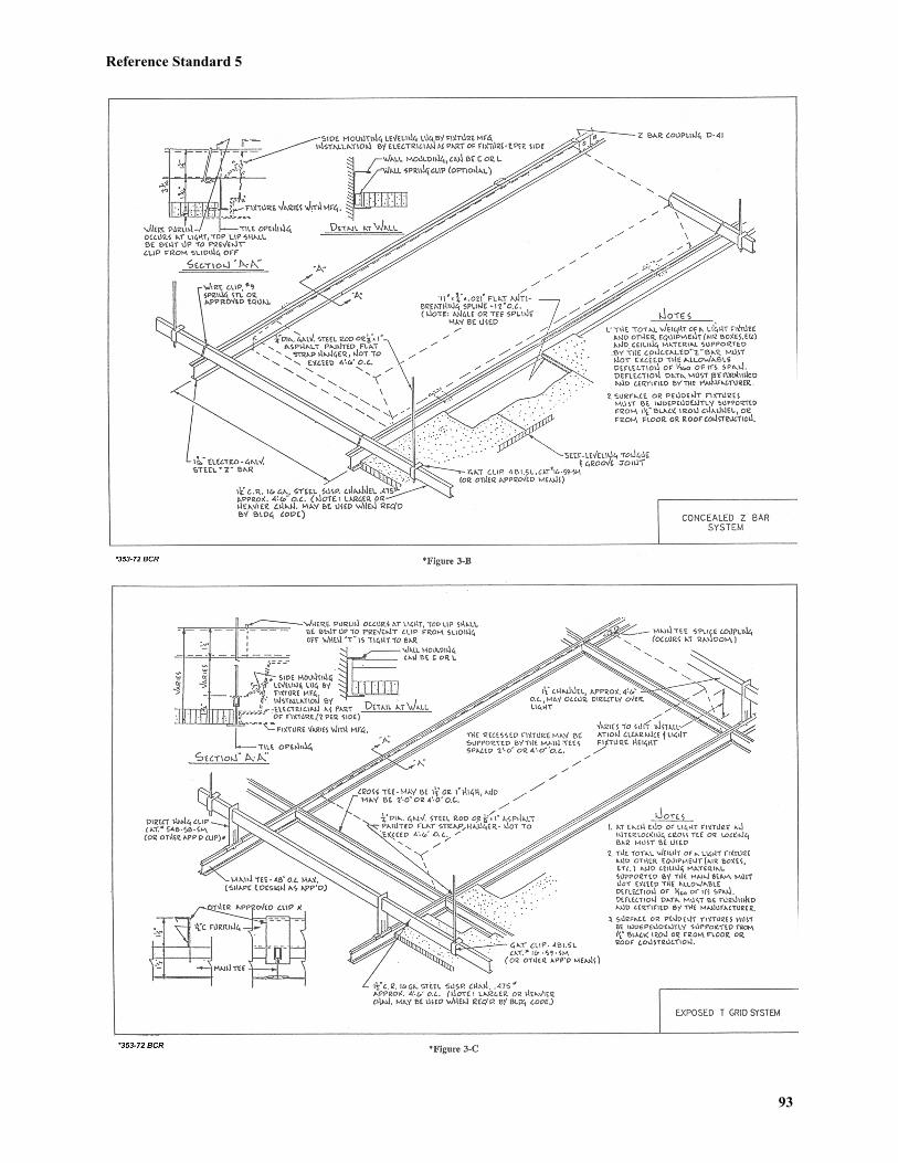
lay-in panel ceilings shall be mounted in a manner thatwill not compromise ceiling performance. Figures 3A,3B and 3C are to be used as a guide.
5.3.2 Maximum fixture weights.-Fixtures exceeding80 lbs. in weight shall be supported independent ofceiling suspension system. Fixtures weighing 80 lbs. orless may be supported from the carrying channels.Fixtures weighing 50 lbs. or less may be supportedfrom the main runners.
5.3.3 Eccentric loading.-Fixtures shall be installedso that the main runners or carrying channels will beeccentrically loaded unless suitable accessory devices(Figs. 3 A, B, C) are employed and the main runnerand/or carrying channel design provides for the torsionalstresses.
5.3.4 Plans.-The plans shall show the necessarydetails of the acoustical ceiling to satisfactorily identifythe number, size, spacing, location, weights, and typesof fixtures and means employed to comply with thissection.
Section 6—Test Method for Determining Deflection6.1 Introduction.-The test method outlined
provides the means by which data can be secured forcharacterizing the structural performance of individualsuspension systems. The method consists of placingstructural members as beams on simple supports, andsubjecting them to simulated uniformly distributedloads over their length. The loading is incrementallyimposed and the performance of the structural memberis obtained from observing the resulting beam deflections.
6.2 Scope.-The test method shall be used forevaluating the load deflection performance of structuralmembers of all acoustical tile and lay-in panelsuspension systems. A simple experimental facility isdescribed which can be adjusted as required to permit
testing of structural members of different sizes, havingvarious section configurations, and on different appropriatespan lengths.
Some suspension systems incorporate a lockingassembly system which enhances performance byproviding some continuity or load transfer capabilitybetween adjacent sections of the ceiling grid. This testmethod does not provide the means for making acomplete evaluation of continuous beam systems, norfor assessing the continuity contribution to overallsystem performance. However, the method can be usedfor evaluating primary structural members in conjunctionwith secondary members which interlock, as well aswith those of noninterlocking type.
6.3 Loading facility.-The loading of structuralmembers shall be performed in a manner which closelysimulates their use in suspension systems. Spandistances, spacing between secondary supports, etc.,shall be typical of ceiling grid designs in which thestructural member is used.
6.3.1 Support frame.-A rectangular support framehaving the essential features of the unit described belowshall be provided.
6.3.1.1 The frame (Fig. 4) shall have the capabilityfor length adjustment to permit testing of structuralmembers on clear spans for a maximum of 8 ft. to aminimum of 3 ft. It shall have the capability for overallwidth adjustment with a maximum length of 4 ft. and aminimum length of 1 ft.
6.3.1.2 The support frame shall have sufficientstiffness so that no significant deflection occurs withinthe frame during load tests of suspension systemstructural members.
6.3.1.3 The support frame may either be ceilingmounted or floor supported.
6.3.2 Test loading.-The main runner weight shallnot be used for evaluating load-deflection performance.One-half the weight of the cross runners shall beincluded as part of the test load.
6.3.2.1 Individual test weights appropriate forevaluating the structural member shall be provided.Loads weighing up to 1 lb. shall be provided so thattheir actual weight is within 0.01 lb. of their markedweight. Weights over 1 lb. shall be within 1 percent oftheir marked weight. Loading weights of the sizesrequired can be conveniently provided by weighinglead shot into cloth bags and tying them closed.
6.3.2.2 A sufficient number of weights of suitablemass shall be provided to permit evaluation of thestructural member through its elastic range by loadingin approximately ten equal load increments. Whenelastic performance of the member under test isexceeded, loading shall continue using a suitablyreduced load increment until significant sectioningyielding has been produced.
Reference Standard 5
91
6.3.2.3 A complete load increment shall be appliedsimulating a uniformly distributed load imposed overthe entire section length before measuring the deflection ofthe structural member.
6.3.2.4 Provision shall be made for imposing testloads on the structural member in a symmetrical manner.
6.3.3 Deflection measurements.-The deflection ofstructural members shall be observed after applicationof each full load increment during the entre test.
6.3.3.1 The deflection of structural members beingtested shall be measured with dial indicators capable ofdirect reading to 0.001 in.
6.3.3.2 Dial indicators shall be mounted from aseparate gauge frame (Fig. 4) having three points ofsupport. The gauge frame shall be supported from thetest loading frame and be properly positioned to locatethe dial stems vertically over the structural memberbeing tested.
6.3.3.3 The dial indicators used shall have sufficienttravel capability to permit the deflection performance ofthe structural members to be observed during the entiretest without requiring resetting.
6.4 Structural members.-The manufacturer,installer, or architect or engineer, shall determine theload-deflection performance.
6.4.1 The structural members tested shall beidentical to the sections used in the final system design.All cutouts, slots, etc., as exist in the system componentshall be included in the sections evaluated.
6.4.2 Allowable mill variations of sheet stockthickness have a significant effect on section stiffnessand load carrying ability. Consequently, load-deflectionstudies of structural members shall utilize sections fabricatedin accordance with system manufacturers publishedmetal thicknesses and dimensions.
6.5 Procedure.-The procedures used for evaluatingperformance of suspension system structural membersshall utilize the general principle of following actualfield installation practice wherever possible. As anexample of the general procedure to be followed, thesetup and testing of a primary structural member isdescribed below.
6.5.1 Experimental setup.-In preparation for testing,the length and width of the support frame shall be adjustedto the typical grid dimensions that are established asappropriate to the evaluation of the structural member.The primary structural member shall be installed alongthe longitudinal centerline of the frame and supported atits end as an essentially simply supported beam (Fig. 4).Where secondary members are used, they shall beinstalled normal to the direction of the primary structuralmember and at the midpoint and quarterpoint locationsalong the test span length. One end of such secondarymembers shall be supported from the side of the test
frame and at the other from the flange of the primarystructural member (Fig. 4.). Clearances between ends ofthe secondary structural member in the test setup shallbe typical of that which exists in the actual ceiling grid.
Where interlocking secondary structural membersare used, they shall be assembled into the centralprimary structural member being tested in customaryfashion and using conventional center distance spacing.The other end of the secondary member shall be simplysupported from the perimeter support frame. Nointerlocking of the secondary member and the perimetersupport frame shall be permitted.
6.5.2 Section loading.-With the structural memberto be evaluated installed in the support frame, the gaugeframe shall be positioned to mount the vertical displacementdeflection dials directly over the test section at themidspan and quarterspan locations at which time dialsare positioned to read zero (Fig. 4). The test loads shallbe applied to the structural member in a mannerrepresentative of that which exists in service. For testpurposes simple wire hangers shall be provided tosuitably introduce the load to the section. Extendingfrom such hangers, attachment wires, cords or lightweightchains shall be provided to permit the preweighedincremental test weights to be added as required. Theweight of hangers, wires, pans, etc. shall be incorporatedas part of the test load.
The test weights, simulating the weight of ceilingtile or panel, shall be applied to the structural memberstarting 6 in. from the end supports, and at 1 ft. intervalsthereafter, always proceeding from the ends toward thecenter of the span in applying load. After the first uniformlydistributed load increment has been applied, the midspanand quarterspan deflection of the structural member shallbe measured and recorded. Loading of the structuralmember shall be continued in the same manner, applyingsuccessive increments of uniformly distributed load andobserving deflections after each increment. Loading shall becontinued until it is apparent that the test section has yielded.
The load deflection performance of secondarystructural members of acoustical tile and lay-in panelceiling systems shall be similarly determined. Theunits shall be set up and tested in a manner appropriateto their use in actual grid systems.
6.6 Experimental data.-A test log shall be preparedto record all pertinent data regarding the structural memberbeing evaluated and the principal accessory items used.Such information as the following shall be provided:
Manufacturer's name.Suspension system identification.Test section identification.Description of section: Measured overall height and
thickness of basic stock, type of material, sectionweight, etc.
Test span length.
Reference Standard 5
92
Spacing of lateral supports.Identification of accessory items and how used.Sketch of experimental setup, giving dimensions of
grid, dial gauge locations, load spacing, etc.Record of the incrementally applied uniformly
distributed loads and the resultant midspan andquarterspan deflection and the resultant midspan andquarterspan deflection measurements for each loading.
6.7 Section performance.-The performance ofstructural members of suspension systems shall berepresented by individual load-deflection plots obtainedfrom tests performed at each different span length usedin service.
6.7.2 The results of replicate tests of threeindividual sections each tested on the same span length,shall be plotted and averaged to obtain a characteristicload-deflection curve for the structural member.
6.7.3 The average load-deflection curve shall beused to establish the maximum uniformly distributed
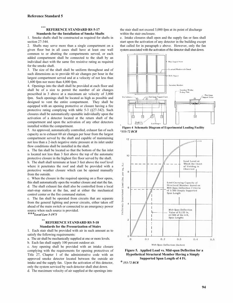
load which the structural member can successfullysustain prior to reaching the deflection limit of 3/360thof the span length in inches (Fig. 5.).
6.7.4 The load-deflection curve shall be used toestablish the maximum loading intensity beyond whichthe structural member begins to yield.
6.8 Suspension system performance.-Publishedperformance data for individual suspension systemsshall be developed by the manufacturer upon the basisof results obtained from load-deflection tests of itsprincipal structural members. Where a ceiling designincorporates a number of components, each of whichexperiences some deflection as used in the system, theadditive nature of these displacements shall be recognizedin setting an allowable system deflection criteria.*
353-72 BCR
Reference Standard 5
93
Reference Standard 5
94
*** REFERENCE STANDARD RS 5-17Standards for the Installation of Smoke Shafts
1. Smoke shafts shall be constructed as required for shafts insection 27-344.2. Shafts may serve more than a single compartment on agiven floor but in all cases shall have at least one wallcommon to or abutting the compartments served, or eachadded compartment shall be connected to the shaft by anindividual duct with the same fire resistive rating as requiredfor the smoke shaft.3. The size of the shaft shall be uniform throughout and ofsuch dimensions as to provide 60 air changes per hour in thelargest compartment served and at a velocity of not less than1,600 fpm nor more than 4,000 fpm.4. Openings into the shaft shall be provided at each floor andshall be of a size to permit the number of air changesprescribed in 3 above at a maximum air velocity of 3,000fpm. Such openings shall be located as high as possible anddesigned to vent the entire compartment. They shall beequipped with an opening protective or closure having a fireprotective rating complying with table 5-3 (§27-342). Suchclosures shall be automatically openable individually upon theactivation of a detector located at the return shaft of thecompartment and upon the activation of any other detectorsinstalled within the compartment.5. An approved, automatically controlled, exhaust fan of suchcapacity as to exhaust 60 air changes per hour from the largestcompartment served by the shaft and capable of maintainingnot less than a 2-inch negative static pressure at its inlet underflow conditions shall be installed in the shaft.a. The fan shall be located so that the bottom of the fan inletis located not less than 3 feet above the top of the automaticprotective closure in the highest fire floor served by the shaft.b. The shaft shall terminate at least 3 feet above the roof levelwhere it penetrates the roof and shall be provided with aprotective weather closure which can be opened manuallyfrom the outside.c. When the closure in the required opening on a floor opens,this shall automatically open the weather closure and start the fan.d. The shaft exhaust fan shall also be controlled from a localstart-stop station at the fan, and at either the mechanicalcontrol center or the fire command station.e. The fan shall be operated from circuits that are separatefrom the general lighting and power circuits, either taken offahead of the main switch or connected to an emergency powersource when such source is provided.***Local Law 5-1973
** REFERENCE STANDARD RS 5-18Standards for the Pressurization of Stairs
1. Each stair shall be provided with air in such amount as tosatisfy the following requirements:a. The air shall be mechanically supplied at one or more levels.b. Each fan shall supply 100 percent outdoor air.c. Any opening shall be provided with an intake closurecomplying with the requirements for opening protectives ofTitle 27, Chapter 1 of the administrative code with anapproved smoke detector located between the outside airintake and the supply fan. Upon the activation of this detector,only the system serviced by such detector shall shut down.d. The maximum velocity of air supplied at the openings into
the stair shall not exceed 3,000 fpm at its point of dischargewithin the stair enclosure.e. Intake closures shall open and the supply fan or fans shallstart upon the activation of any detector in the building exceptthat called for in paragraph c above. However, only the fansystem associated with the activation of the detector shall shut down.
* Figure 4 Schematic Diagram of Experimental Loading Facility*353-72 BCR
* Figure 5. Applied Load vs. Mid-span Deflection for aHypothetical Structural Member Having a Simply
Supported Span Length of 4 Ft.* 353-72 BCR
Reference Standard 5
2. An approved, automatically controlled louver and weather closure open to the exterior at the highest floor served by the stair shall be installed in the case of a fan or fans producing an upward flow of air, or at the furthest point or points from the fan or fans when more than one fan is used, or at the lower end of the stair venting to outside if a single fan is located at the upper end of the shaft. The size shall be not less than 2 sq. in. per 100 cu. ft. of total shaft volume. Any existing fixed ventilating opening may be included in meeting this requirement. The louver shall be normally closed and shall open automatically by fusible link or other approved device when subjected to a temperature of 135oF. or to a rapid rise in temperature at a rate of 15 to 20oF. per minute, and the louver shall also be remotely operable from the fire command center. Such louver shall also satisfy the requirements of subdivision d of section 27-344. 3. The total supply of air introduced into each stair shall be equal to and not less than the algebraic sum of 24,000 cfm plus 200 cfm per story of stair. 4. Other operating requirements. a. All weather closures may normally be in closed position. b. The air supply fans shall provide positive pressure differential between the stair shaft and each floor at a maximum of 0.4 inches of water column whether doors are open or closed. Minimum positive pressure differentials between the stair shafts and each floor of 0.10 inches of water column when all doors are closed, and no less than 0.050 inches of water column when any three doors are open, shall be maintained. As an alternative to the maintenance of 0.050 inches of water column, a minimum average velocity of 400 feet per minute, measured in the plane of any open door, with any three doors open, shall be maintained. c. Excess positive pressure within the stair closure may be relieved at one or more levels through protected openings in the stair enclosure in the following manner: (1) Each opening shall be provided with an approved adjustable barometric backdraft damper so arranged as to permit air flow out of the stair enclosure only and shall be adjusted to close if the pressure differential is less than 0.05 inches of water column, and to remain open if the pressure differential is greater than 0.4 inches of water column. (2) Each opening shall be protected with two 1 1/2-hour fire dampers arranged in series, each with fusible links rated to melt at 125oF. (3) Acceptable alternative systems for the relief of excessive positive pressure other than through the protective openings in the stair enclosure may be installed, subject to the approval of the Commissioner. (4) Spill ducts located entirely within the stair enclosure and utilizing barometric dampers may be installed as an acceptable alternative system referred to in sub-paragraph 3 above. d. Air supply fans shall also be controlled from a local
start-stop station at the fans and from the fire command station. In addition, fan controls may also be located at the mechanical control center. These controls shall over-ride the automatic detection shut-down. e. The fans shall be operated from circuits that are separate from the general lighting and power circuits taken off ahead of the main switch and connected to an emergency power source when such source is provided. *** 5. Full system testing shall be required for each installation and shall be subject to controlled inspection. Pressure or velocity measurements shall be taken for the purpose of determining whether the desired control of smoke will be established and reports of such measurements shall be made and copies thereof filed with the department as provided in Section 27-132 for controlled inspection. A full system test shall be performed after any construction and/or modifications to the stair enclosures altering the volume of such enclosures. *** 6. Operational tests of the stair pressurization systems shall be conducted every twelve months by building maintenance personnel and witnessed by the Fire Safety Director or by a Registered Architect or Professional Engineer to ensure that each system functions. The owner or his authorized representative shall retain at the premises a record of each test performed for Building and Fire Departments' use. *** 7. Operational tests shall determine that initiating devices such as fire alarms, sprinkler alarms, elevator recall, manual switches, and smoke detectors other than those designed to cause the shutdown of outside air intake systems, will cause the stair pressurization systems' intake dampers to open and fans to start. ** Local Law 84-1979 ***DOB 8-26-98
* REFERENCE STANDARD RS 5-19 ASTM E814-1983 Standard Method of Fire Tests of Through-Penetration Fire Stops. *Local Law 16-1984; 1343-88 BCR
* REFERENCE STANDARD RS 5-20 Standards for the flammability of Carpets
DOC FF 1-1970 Methane Pill Test. ASTM E648-1988 Standard Test Method for Critical Radiant Flux of Floor Covering Systems Using a Radiant Heat Source. ASTM E662-1988 Standard Test Method for Specific Optical Density of Smoke Generated by Solid Materials. *Local Law 16-1984; 1343-88 BCR
*** REFERENCE STANDARD RS 5-21 UBC Std. 26-9-1997 Method of Test for the Evaluation of Flammability Characteristics of Exterior, NonloadBearing Wall Assemblies Containing Combustible Components Using the Intermediate-Scale,Multistory Test Apparatus. ***DOB 3-4-01; Local Law 13-1987; 1343-88 BCR