27
Refill Friction Spot Joining Hideki Okada Kawasaki Heavy Industries, Ltd., Japan 7 th International EWI/TWI Seminar on Joining Aerospace Materials September 17, 2014 – September 18, 2014

Refill Friction Spot Joining
Hideki Okada
Kawasaki Heavy Industries, Ltd., Japan
7th International EWI/TWI Seminar on
Joining Aerospace Materials
September 17, 2014 – September 18, 2014
© 2014 Kawasaki Heavy Industries, Ltd. All Rights Reserved 2
INDEX
1.Introduction
2.Process and features of FSJ
3.Evaluation of Joint properties
4. Actual prototype trial
5.Conclusion

© 2014 Kawasaki Heavy Industries, Ltd. All Rights Reserved 3
1.Introduction
About us, Kawasaki Heavy Industries,LTD.
© 2014 Kawasaki Heavy Industries, Ltd. All Rights Reserved 4
1.Introduction
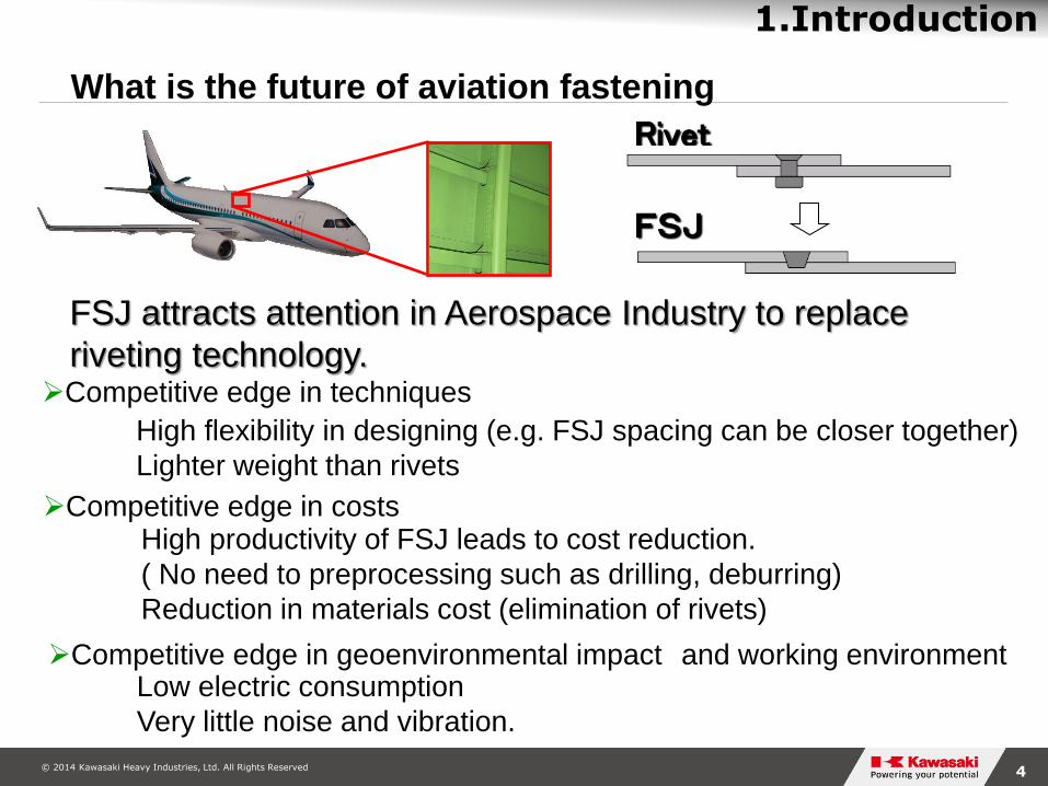
Rivet
FSJ attracts attention in Aerospace Industry to replace
riveting technology.
FSJ
Competitive edge in techniques
Competitive edge in costs
Competitive edge in geoenvironmental impact and working environment
High flexibility in designing (e.g. FSJ spacing can be closer together)
Lighter weight than rivets
Low electric consumption
Very little noise and vibration.
High productivity of FSJ leads to cost reduction.
( No need to preprocessing such as drilling, deburring)
Reduction in materials cost (elimination of rivets)
What is the future of aviation fastening
© 2014 Kawasaki Heavy Industries, Ltd. All Rights Reserved 5
1.Introduction
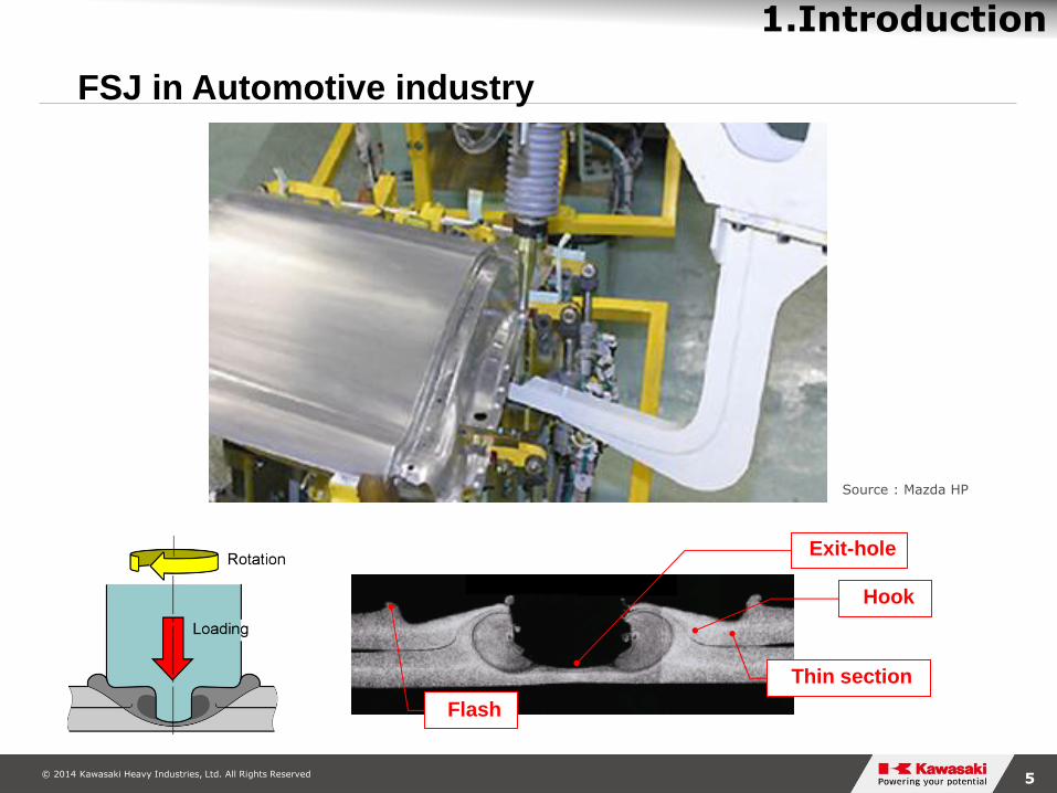
FSJ in Automotive industry
Exit-hole
Flash
Hook
Thin section
Source : Mazda HP
© 2014 Kawasaki Heavy Industries, Ltd. All Rights Reserved 6
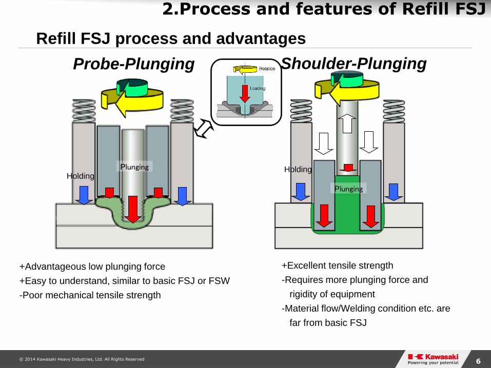
Plunging Holding
Probe-Plunging
Refill FSJ process and advantages
+Advantageous low plunging force
+Easy to understand, similar to basic FSJ or FSW
-Poor mechanical tensile strength
Plunging
Holding
Shoulder-Plunging
2.Process and features of Refill FSJ
+Excellent tensile strength
-Requires more plunging force and
rigidity of equipment
-Material flow/Welding condition etc. are
far from basic FSJ

© 2014 Kawasaki Heavy Industries, Ltd. All Rights Reserved 7
2.Process and features of Refill FSJ
Cut model animation of shoulder plunging process

© 2014 Kawasaki Heavy Industries, Ltd. All Rights Reserved 8
2.Process and features of Refill FSJ
3 servo motors in refill FSJ gun provides tools rotation, shoulder and probe motions independently.
Refill FSJ gun has high Z force (up to 14.7kN) and can join up to t4mm(Upper-sheet) of aluminum alloy and some other materials.
Refill FSJ systems developed by KHI

© 2014 Kawasaki Heavy Industries, Ltd. All Rights Reserved 9
3.Evaluation of Joint properties
1) Al2024C-T3 .032InT
evaluation of material lot 2) Al2024C-T3 Alodine
coated material
evaluation of ED,
fatigue etc.
3) Within sealant material
© 2014 Kawasaki Heavy Industries, Ltd. All Rights Reserved 10
3.Evaluation of Joint properties
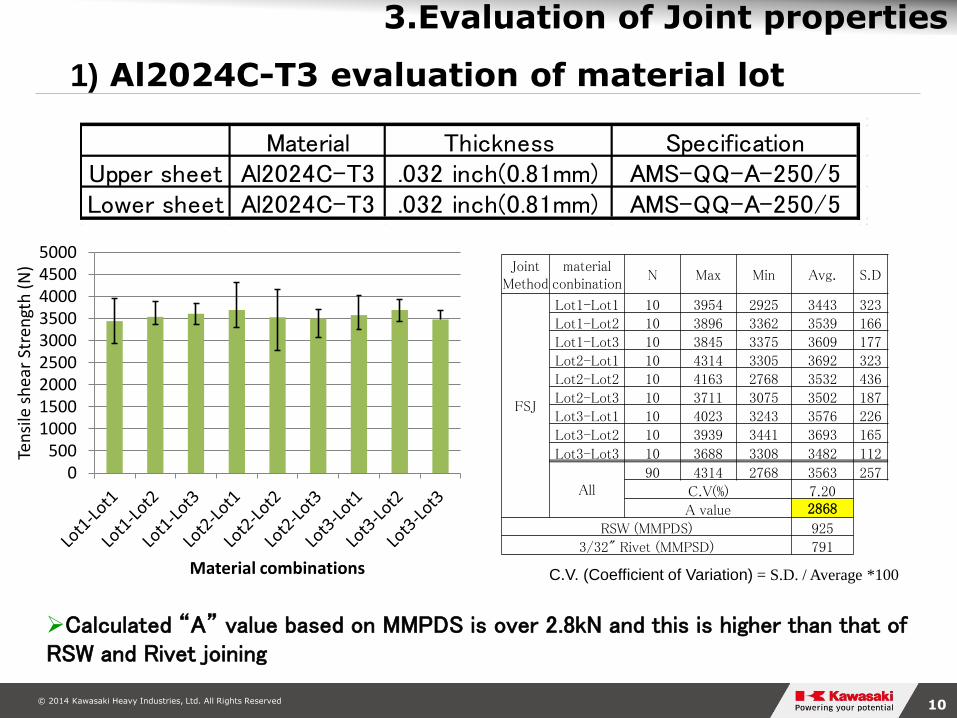
1) Al2024C-T3 evaluation of material lot
Material Thickness SpecificationUpper sheet Al2024C-T3 .032 inch(0.81mm) AMS-QQ-A-250/5Lower sheet Al2024C-T3 .032 inch(0.81mm) AMS-QQ-A-250/5
Joint Method
material conbination
N Max Min Avg. S.D
FSJ
Lot1-Lot1 10 3954 2925 3443 323
Lot1-Lot2 10 3896 3362 3539 166
Lot1-Lot3 10 3845 3375 3609 177
Lot2-Lot1 10 4314 3305 3692 323
Lot2-Lot2 10 4163 2768 3532 436
Lot2-Lot3 10 3711 3075 3502 187
Lot3-Lot1 10 4023 3243 3576 226
Lot3-Lot2 10 3939 3441 3693 165
Lot3-Lot3 10 3688 3308 3482 112
All 90 4314 2768 3563 257
C.V(%) 7.20
A value 2868
RSW (MMPDS) 925
3/32" Rivet (MMPSD) 791
Calculated “A” value based on MMPDS is over 2.8kN and this is higher than that of RSW and Rivet joining
C.V. (Coefficient of Variation) = S.D. / Average *100
0500
100015002000250030003500400045005000
Ten
sile
sh
ear
Stre
ngt
h (
N)
Material combinations

© 2014 Kawasaki Heavy Industries, Ltd. All Rights Reserved 11
3.Evaluation of Joint properties
0
500
1000
1500
2000
2500
3000
3500
1) Relationship between thickness and tensile shear strength
Thickness of upper sheet [inch]
Shea
r str
ength
[N
]
0.020 0.025 0.032 0.040
0.020”
0.025”
0.032”
0.040”
Thickness of lower
shetet
0.020”/0.020”
0.020”/0.025”
0.020”/0.032”
0.020”/0.040”
0.025”/0.020”
0.025”/0.025”
0.025”/0.032”
0.025”/0.040”
0.032”/0.025”
0.032”/0.032”
0.032”/0.040”
0.040”/0.032”
0.040”/0.040”
Thickness of
upper sheet[inch]
Thickness of
lower sheet[inch]0.020 0.025 0.032 0.040 0.020 0.025 0.032 0.040 0.025 0.032 0.040 0.032 0.040
Number 10 10 10 10 10 10 10 10 10 10 10 10 10
Max [N] 2101 1890 2205 2600 1705 2090 2231 2355 2202 2741 2345 2851 3117
Min [N] 1433 1568 1744 2055 1317 1578 1964 2178 1680 2323 2140 2394 2702
Average [N] 1854 1787 1929 2277 1548 1880 2082 2281 1973 2560 2249 2611 2960
0.020 0.025 0.0400.032
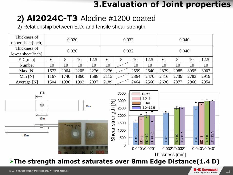
2) Al2024C-T3 Alodine #1200 coated
The strength tends to increase with increasing the thickness of upper and lower sheets.
© 2014 Kawasaki Heavy Industries, Ltd. All Rights Reserved 12
3.Evaluation of Joint properties
0
500
1000
1500
2000
2500
3000
3500ED
Shea
r str
ength
[N
]
Thickness [mm]
Thickness of
upper sheet[inch]
Thickness of
lower sheet[inch]
ED [mm] 6 8 10 12.5 6 8 10 12.5 6 8 10 12.5
Number 10 10 10 10 10 10 10 10 10 10 10
Max [N] 1672 2064 2205 2276 2276 2599 2640 2879 2985 3095 3007
Min [N] 1167 1740 1860 1588 2115 2364 2470 2416 2739 2783 2919
Average [N] 1504 1930 1993 2037 2189 2464 2560 2636 2877 2966 2954
0.020 0.032 0.040
0.020 0.032 0.040
0.020”/0.020” 0.032”/0.032” 0.040”/0.040”
ED=6
ED=8
ED=10
ED=12.5
ED
=6
ED
=8
ED
=1
0
ED
=1
2.5
ED
=6
ED
=10
ED
=1
2.5
ED
=6
ED
=8
ED
=1
0
ED
=12
.5
2) Relationship between E.D. and tensile shear strength
2) Al2024C-T3 Alodine #1200 coated
The strength almost saturates over 8mm Edge Distance(1.4 D)

© 2014 Kawasaki Heavy Industries, Ltd. All Rights Reserved 13
3.Evaluation of Joint properties
Pitch
72mm
Thickness of
upper sheet[inch]
Thickness of
lower sheet[inch]
Pitch [mm] 6 10 20 24 6 10 20 24 6 10 20 24
Number 10 10 10 10 10 10 10 10 10 10 10 10
Max [N] 4420 5363 6057 6563 5869 7608 8323 8182 5946 7666 8712 8911
Min [N] 3977 4807 5047 4673 4971 7126 7679 7656 5493 6997 8078 8461
Average [N] 4141 5049 5543 5610 5392 7317 8057 7922 5757 7391 8520 8636
0.020 0.032 0.040
0.020 0.032 0.040
0
2000
4000
6000
8000
10000
She
ar
str
eng
th [
N]
0.020”/0.020” 0.032”/0.032” 0.040”/0.040”
Pitch=6
Pitch=10
Pitch=20
Pitch=24
Pitch
=6
Pitch
=1
0
Pitch
=2
0
Pitch
=2
4
Pitch
=6
Pitch
=1
0
Pitch=
20
Pitch
=2
4
Pitch
=6
Pitch
=1
0
Pitch
=2
0
Pitch
=2
4
3) Relationship between Joint pitch and tensile shear strength
2) Al2024C-T3 Alodine #1200 coated

© 2014 Kawasaki Heavy Industries, Ltd. All Rights Reserved 14
3.Evaluation of Joint properties
Number of Cycles
Parc
ent
of sta
tic s
trength
of
join
t (%
)
0.040”/0.020”
0.040”/0.025”
0.040”/0.032”
0.040”/0.040”
Spot Welding Joint (MMPDS)
125
25
25
12.5
Thickness
[inch]
0.020
/0.040
0.025
/0.040
0.032
/0.040
0.040
/0.040Rifill FSJ [N]
(Average)2277 2281 2249 2960
RSW [N]
(MMPDS)498 658 925 1228
4) Joint lap fatigue test(unguided)
2) Al2024C-T3 Alodine #1200 coated

© 2014 Kawasaki Heavy Industries, Ltd. All Rights Reserved 15
3.Evaluation of Joint properties
Clad material
Disappearance of interface
Φ 6.11mm = SZ
Al Cu
Cr O
Upper sheet
Al2024C-T3
Lower sheet
Al2024C-T3
2) Al2024C-T3 Alodine #1200 coated 5) Cross section and EPMA analysis
Scattered chrome and oxygen were observed in the clad material., but enough mixing and dividing by mechanical stirring

© 2014 Kawasaki Heavy Industries, Ltd. All Rights Reserved 16
3.Evaluation of Joint properties
Al Cu
Upper sheet
Al2024C-T3
Lower sheet
Al2024C-T3
50mm
450mm
750mm 950mm
2) Al2024C-T3 Alodine #1200 coated 6) Tomographic EPMA analysis
Clad material was observed all circumferences of stir zone.
© 2014 Kawasaki Heavy Industries, Ltd. All Rights Reserved 17
3.Evaluation of Joint properties
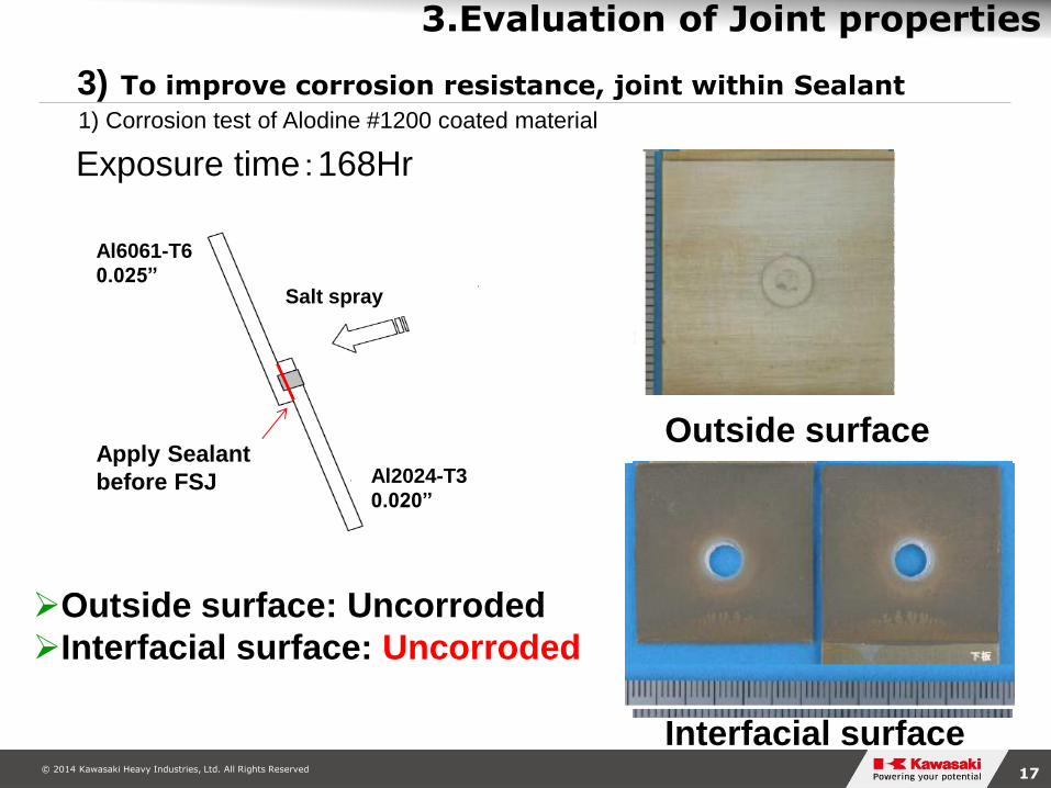
Exposure time:168Hr
Al2024-T3
0.020”
Salt spray
Al6061-T6
0.025”
Apply Sealant
before FSJ
Outside surface
Interfacial surface
Outside surface: Uncorroded
Interfacial surface: Corroded
Outside surface: Uncorroded
Interfacial surface: Uncorroded
3) To improve corrosion resistance, joint within Sealant
1) Corrosion test of Alodine #1200 coated material
© 2014 Kawasaki Heavy Industries, Ltd. All Rights Reserved 18
3.Evaluation of Joint properties
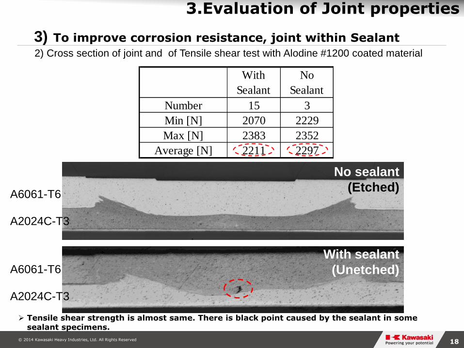
With
Sealant
No
Sealant
Number 15 3
Min [N] 2070 2229
Max [N] 2383 2352
Average [N] 2211 2297
A6061-T6
A2024C-T3
With sealant
(Unetched)
A6061-T6
A2024C-T3
No sealant
(Etched)
3) To improve corrosion resistance, joint within Sealant
2) Cross section of joint and of Tensile shear test with Alodine #1200 coated material
Tensile shear strength is almost same. There is black point caused by the sealant in some sealant specimens.
© 2014 Kawasaki Heavy Industries, Ltd. All Rights Reserved 19
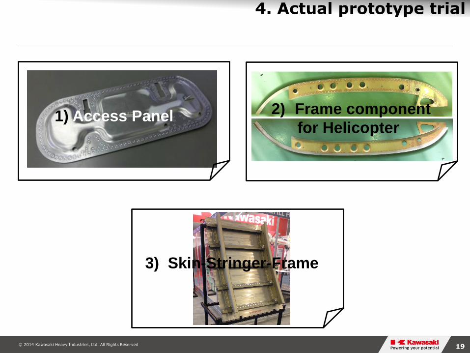
1) Access Panel 2) Frame component
for Helicopter
3) Skin-Stringer-Frame
4. Actual prototype trial

© 2014 Kawasaki Heavy Industries, Ltd. All Rights Reserved 20
4. Actual prototype trial
1) Access Panel
Material ThicknessOuter Skin Al2024C-T42 .032 inch(0.81mm)Inner Skin Al2024C-T42 .032 inch(0.81mm)Small crip Al2024C-T3 .032 inch(0.81mm)
Parts before joining
Outside view of joined panel
Inside view of joined panel
© 2014 Kawasaki Heavy Industries, Ltd. All Rights Reserved 21
4. Actual prototype trial
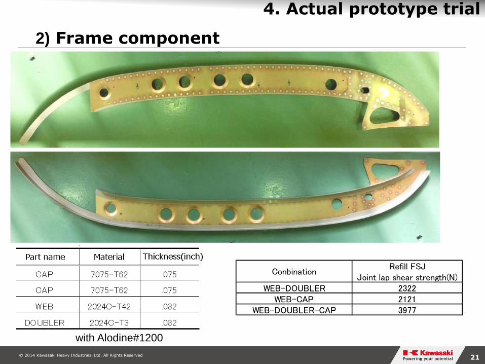
with Alodine#1200
ConbinationRefill FSJ
Joint lap shear strength(N)WEB-DOUBLER 2322
WEB-CAP 2121WEB-DOUBLER-CAP 3977
2) Frame component

© 2014 Kawasaki Heavy Industries, Ltd. All Rights Reserved 22
4. Actual prototype trial
2) Frame component
Riveted Frame(as reference)
Refill-FSJed Frame

© 2014 Kawasaki Heavy Industries, Ltd. All Rights Reserved 23
4. Actual prototype trial
With Anodize Faying sealant at the interface
3) Skin-Stringer-Frame

© 2014 Kawasaki Heavy Industries, Ltd. All Rights Reserved 24
4. Actual prototype trial
3) Skin-Stringer-Frame(Close up picture)

© 2014 Kawasaki Heavy Industries, Ltd. All Rights Reserved 25
4. Actual prototype trial
3) Skin-Stringer-Frame (1st Trial movie)

© 2014 Kawasaki Heavy Industries, Ltd. All Rights Reserved 26
5.Conclusion
Refill FSJ Joint lap shear strength is impressive in
comparison to RSW and riveting.Even though Alodine,
Chromic Acid Anodize material, and with faying sealant
material.
Newly developed refill FSJ robot system can join aircraft
trial parts successfully. This technology has a potential
to produce parts at a high rate with high quality.
© 2014 Kawasaki Heavy Industries, Ltd. All Rights Reserved 27
Thank you for your kind attention


