In optical shop testing the evaluation of aberrationsis a very important issue. A variety of optical inter-ferometric techniques have been developed and pro-posed for this purpose. Basically there are twoclasses of interferometric methods: that of theTwyman–Green and the Mach-Zendher interferom-eters that directly map the wave front W~x, y! and inwhich the aberrated tested wave front is made tointerfere with a reference wave front and that ofshearing interferometers in which the aberratedtested wave front is made to interfere with its ownreplica after it has been sheared in some directionand amount. The shear can be lateral, angular, ra-dial, or reversal. In shearing interferometry thefringe pattern gives direct information about theslope of the wave front rather than the wave frontW~x, y! itself. In this case, to obtain the wave front,it is necessary to integrate the fringe shape, and er-rors become large with the increasing the shear. Re-versal interferometers ~RIs! have a special propertythat distinguishes them from other interferometers.
The authors are with Istituto di Cibernetica del Consiglio Na-zionale delle Ricerche, Via Toiano 6, I-80072 Arco Felice ~NA!,Italy. P. Ferraro is also with Istituto Tecnico Industriale Statale“VIII-Augusto Righi,” V. le J. F. Kennedy 112, 80125 Napoli, Italy.S. De Nicola’s e-mail address is [email protected].
Received 19 January 1999; revised manuscript received 10 May1999.
In fact, RI’s can be made with no sensitivity to sym-metric aberrations like defocusing, spherical aberra-tion, and astigmatism. They are sensitive only toasymmetric aberrations and are widely used when iso-lated measurement of coma is desired. Two extensivereviews about the RI and its applications are reportedby Bryngdahl1 and Malacara.2 Moreover, the RI havethe prerogative to be doubly sensitive to coma. In theliterature, several reversal or inverting interferom-eters are reported, and essentially, three basic types ofRI’s have been invented: ~a! slight modifications ofthe Twyman–Green and the Fizeau interferometers3,4;b! prism RI’s5–7; and ~c! configurations that make use
of holographic optical elements.8,9 Interferometers oftype ~a! and ~b! generally make use of custom-madeoptics; both configurations are expensive for that rea-son. Furthermore, the alignment procedures arerather tedious in these configurations. Type ~c! inter-ferometers seem to be more flexible but involve a two-step process: recording and reconstruction of ahologram. This process can be very time consumingand impractical.
We describe the reflective grating interferometer~RGI! as a new and alternative folded and reversalconfiguration. The RGI interferometer has been al-ready proposed for measurement of the index of re-fraction of solids10 and liquids11 and for measurementof the focal length of lenses.12,13 Here, the RGI isinterpreted as a folded and reversing interferometer.We propose this wave front RI for detection of aber-rations introduced by optical systems and especiallywhen isolated detection of coma is necessary.
The RGI can also be used in an asymmetric config-
1 August 1999 y Vol. 38, No. 22 y APPLIED OPTICS 4845
a
g
c
wbr
Tccerao
np
4
uration in respect to the tested wavefront; in this caseit behaves like a reversing shearing interferometer,becoming sensitive also to symmetrical third-orderaberrations. The interferometer is simple to alignand is made only of two components: a mirror and areflective grating. It is very flexible because a car-rier can simply be added in the fringe pattern, allow-ing the use of the digital Fourier transform methodfor fringe pattern analysis.
2. Theory and Principle of Operation of theInterferometer
Only two optical components, a mirror and a reflec-tive diffraction grating that is 1200 linesymm makethe RGI. A collimated wavefront W~x, y! is dividedspatially in two half-wave-fronts W1~x, y! for y . 0nd W2~x, y! for y , 0 by the mirror and the grating
~Fig. 1!. The wavefront W2~x, y! is reflected onto thegrating by the mirror. The angle of incidence of thetwo wavefronts W1~x, y! and W2~x, y! on the grating
Fig. 1. RGI; M, mirror; and G, diffraction grating. The wave-front W~x, y! is divided spatially by the RGI. The half-wave-frontW2~x, y! is folded and reversed onto the half-wave-front W1~x, y!.For clarity, the wave front W~x, y! has been represented with onlycoma aberration. OPD is the optical path difference produced bythe two comatic half and reversed wave fronts.
846 APPLIED OPTICS y Vol. 38, No. 22 y 1 August 1999
is such that both are diffracted along the normal ofthe reflective grating. The wavefront W2~x, y! isclearly folded on the other wavefront W1~x, y!. Thetwo wavefronts interfere, giving place to a nonlocal-ized fringe pattern in front of the grating. A CCDcamera allows the visualization of the resultingfringe pattern.
Different cases can occur. The wavefront W~x, y!is an aberration-free plane wave, which, in this case,makes the two wavefronts W1~x, y! and W2~x, y! alsoplane waves and produces a null fringe pattern. Ifthe mirror and the grating are not mutually perpen-dicular, then a fringe pattern made of parallel andequally spaced fringes is obtained. A second case isthat of the wavefront W~x, y! being nearly a planewave ~collimated beam! but affected by third-orderprimary aberrations; if the wavefront is symmetricwith respect to the mirror and grating, then one halfof the wavefront is folded onto the other. As derivedby Kingslake14 in 1925, the wave-front distortionW~x, y! due to primary aberrations is given by theeneral expression
W~x, y! 5 A~x2 1 y2!2 1 By~x2 1 y2! 1 C~x2 1 3y2!
1 D~x2 1 y2! 1 Ex 1 Fy, (1)
where each term represents a different type of aber-ration as follows: A 5 spherical aberration, B 5oma, C 5 astigmatism, D 5 defocusing, E 5 tilt
about the y axis, and F 5 tilt about the x axis. Theave-front division and folding operations producedy the mirror and the grating of the RGI cause aeversal of the wavefront W2~x, y!. Then the two
half-wave-fronts as divided by the RGI, W1~x, y! andW2~x, y!, can be written as
he interferometer can be aligned in such a way toompensate for tilt along the y axis. In fact, theouple grating mirror can be positioned having themerging diffracted wavefronts along the normal di-ection of the grating. The resulting fringe patternt the exit port of the interferometer is due to theptical phase difference
OPD~x, y! 5 W1~x, y! 2 W2~x, y! 2 2Fy
~Fig. 1!, resulting in
OPD~x, y! 5 2By~x2 1 y2!. (3)
The only term contained in this expression is comaaberration; in this case the interferometer is sensitiveonly to the asymmetric terms, and all symmetricterms of Eq. ~1! disappear.
A third case occurs when the wavefront W~x, y! isearly a plane wave that is affected by third-orderrimary aberrations but that does not impinge on the
ofo
hf
5Tt
a
a
T
a
couple mirror grating symmetrically with respect to zaxis of Fig. 1. Then the wavefront is not foldedabout the diameter but about another axis parallel tothe x axis. In this case if we consider the wavefrontW~x, y! expressed by the Eq. ~1!, then the fringe pat-tern is produced by the optical phase difference
OPD~x, y! 5 W1~x, y! 2 W2~x, S 2 y!.
In this case the wavefront W2~x, y! is folded but alsolaterally sheared in respect to W1~x, y!. The RGI inthis configuration becomes a half-folded reversalshearing interferometer. The amount of the shear Sdepends on the amount of asymmetry, as shown inFig. 1. In particular, a shear S is obtained when thewavefront is shifted laterally by an amount of Sy2 inrespect to the z axis. In this configuration RGI issensitive to all terms of aberrations, both symmetricand asymmetric. In this paper we limit the discus-sion to the symmetric case when the RGI is sensitiveonly to coma. It is important to say that in case of anoncollimated beam, the RGI introduces, in both thecited configurations, also a longitudinal shear, owingto the different optical path lengths experienced bythe two half-wave-fronts in reaching the diffractiongrating.
3. Third-Order Aberration of a Parabolic Mirror UsedOff Axis
An example of the application of the RGI as a RI is indetection of the third-order aberrations that are pro-duced by a centered parabolic mirror used at fieldangle u to collimate a He–Ne laser beam ~wavelengthl 5 632.8 nm!. The system geometry is shown inFig. 2. The parabolic mirror, which has a diameterof 20 cm and a focal length of f 5 750 mm, is set atapproximately one focal length from the microscopeobjective ~253! used to expand the beam. The widthf the grating is D 5 44 3 44 mm, and its spatialrequency is 1200 linesymm corresponding to a pitchf d 5 0.83 mm.
Fig. 2. Experimental configuration for testing coma of a parabolicmirror used at angle u. G, grating; M, mirror; and PP, photoplate.
The half-wave-front WA, reflected onto the gratingby the mirror, is folded around the x axis onto the
alf-wave-front WB and diffracted along the 21 dif-raction order. The half-wave-front WB incident
onto the diffraction grating at angle a 5 arcsin~lyd!49.4° is diffracted along the 11 diffraction order.
he mirror M and the grating G are positioned at 90°o each other such that the two 11 and 21 interfering
diffraction orders are collinearly directed along thegrating normal. Since we are interested in analyz-ing the whole interference fringe pattern diffractedby the grating, we used a photoplate to record it. Asa second step, we have imaged by a suitable imagingoptic the negative of the photoplate onto the smallerarea of a CCD camera so that a fringe pattern digi-tized into a 512 3 512 pixel array for subsequentfringe analysis could be obtained.
Referring to Fig. 2, we assume without loss of gen-erality that the spherical source S~h, j! is located inthe horizontal y–z plane and that its coordinates aregiven j ' f and h ' 2SV tan~u! ' 2fu for small angleu, with SV ' fycos~u! ' f ~1 1 u2y2! being the distanceof the source from the paraboloid vertex. Now theoptical path length OPLSVH of a ray reflected at thevertex of the parabolic mirror V, which intercepts atpoint H the aberrated wavefront A9B9 is given by
OPLSVH 5 SV 1 VH.
The point H is the origin of the coordinate system ~x9y9 z9! counterclockwise rotated of angle u around thex axis. If we take into account that the coordinateszH and yH of the point H are given by
zH 5 cos2~u!z 1 sin~u!cos~u!y, (4a)
yH 5 sin~u!cos~u!z 1 sin2~u!y, (4b)
respectively, where z and y are the coordinates of And satisfy the paraboloid equation
z 5 ~x2 1 y2!y4f
nd if we approximate the distance
VH 5 ~yH2 1 zH
2!1y2
to the second order in u by
VH < ~1 2 u2y2!z 1 uy,
the optical path length OPLH, can be written as
OPLSVH 5 f 1 z 1 ~ f 2 z!u2
21 uy. (5)
he optical path length OPLSAA of a ray reflected ata point A of the paraboloid ~Fig. 2!, which interceptst point A9 the wavefront A9B9, is given by
OPLSAA9 5 @x2 1 ~y 2 h!2 1 ~z 2 j!2#1y2 1 z9 (6)
where z9 5 AA9 is coordinate of a point A9 of theaberrated wavefront in the rotated system. To de-termine z9~x, y, z! as a function of the coordinates ofA, we equate Eqs. ~5! and ~6! and consider that in ourcondition ~zyf !2 ,, 1. Hence by developing the
1 August 1999 y Vol. 38, No. 22 y APPLIED OPTICS 4847
t
wa
t
4
square root in Eq. ~6! to the second order and byretaining terms up to u2 we obtain
where the coma coefficient is B 5 uy4f2, the astigma-ism is C 5 u2y4f, and the defocusing is D 5 2u2y4f.
A ray reflected from a generic point A of the parabo-loid mirror with coordinates x, y, and z intercepts thex9–y9 plane of the rotated system at coordinates x9and y9 related to the unprimed quantities by the fol-lowing relations
x 5 x9, (7a)
y 5 y9 1 uz, (7b)
which hold for small angle u. Hence if we substituteEqs. ~7a! and ~7b! into Eq. ~7! and, according to ourapproximations, neglect terms of order higher thanu2, we easily verify that Eq. ~7! still holds in theprimed system of coordinates with x and y replaced byx9 and y9.
The anamorphic shaping of the wavefront due tothe grating illumination at angle a needs to be takeninto account to determine the interference betweenthe two half-wave-fronts WA and WB. In fact, theeffective dimension H9B0 5 D cos~a! 5 28.6 mm alongthe y9 axis of half the reflected wavefront that isincident onto the grating corresponds to a width ofD 5 44 mm of the interference pattern recorded ontothe photoplate ~Fig. 2!, whereas the shape of the
avefront along the vertical x9 axes is unmodifiedfter being diffracted by the grating.According to the considerations of the previous sec-
ion, the intensity distribution I~x, y! of the interfer-ence fringe pattern in the x–y plane of the photoplate
Fig. 3. Fringe pattern recorded by the photoplate.
848 APPLIED OPTICS y Vol. 38, No. 22 y 1 August 1999
is essentially determined by the coma coefficient B 5uy4f2 and can be written in the following form
I~x, y! 5 I0~x, y!@1 1 cos DF~x, y!#, (8)
where the phase term is given
DF~x, y! 52p
lOPD~x, y!, (9)
and the optical path difference between the wave-fronts WA and WB is given by
OPD~x, y! 5 2B cos~a!y@x2 1 cos2~a!y2#. (10)
Figure 3 shows the recorded fringe pattern with asmall carrier added to allow the application of theFourier-transform-based algorithm for phase retriev-al.13 The parabolic mirror was set off axis with anangle of u 5 15°.
We added the carrier by slightly tilting the mirrorof the interferometer. The RGI is very flexible be-
Fig. 4. Wrapped phase map computed of the fringe pattern shownin Fig. 3.
Fig. 5. Unwrapped phase map of the comatic interference pat-tern.
1
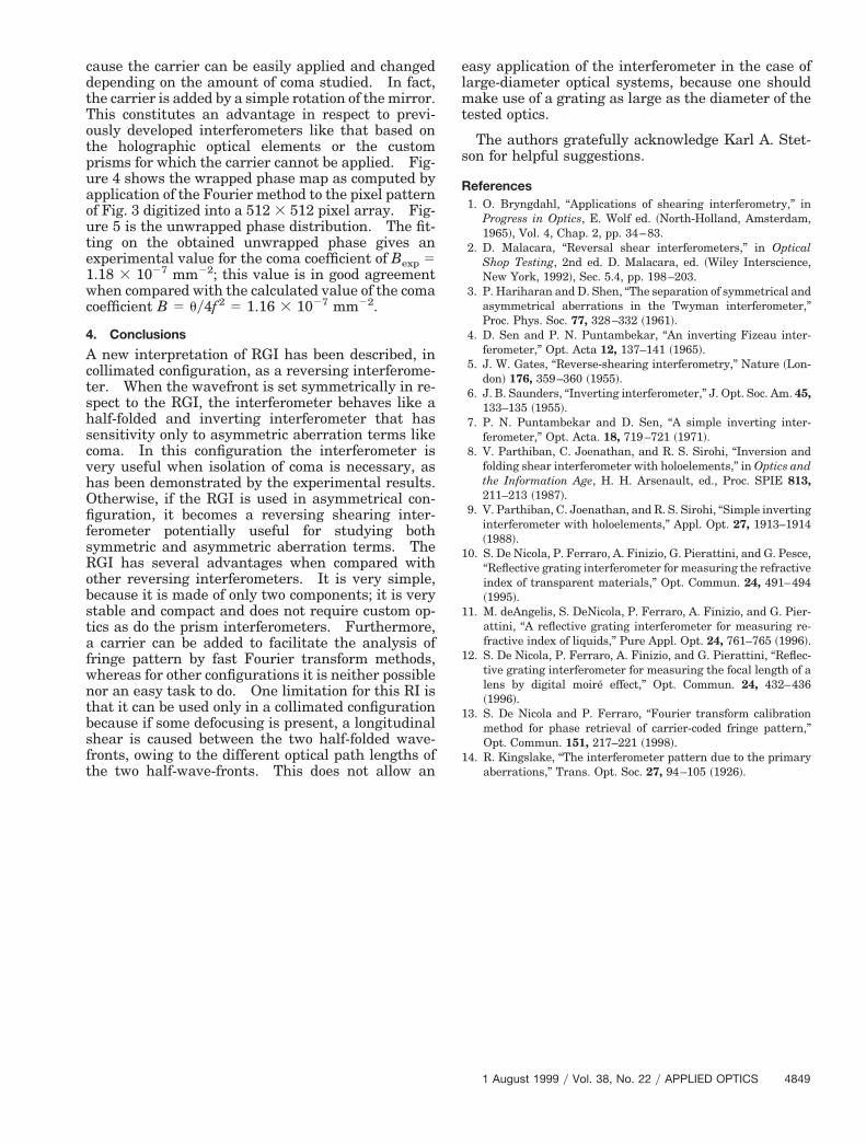
cause the carrier can be easily applied and changeddepending on the amount of coma studied. In fact,the carrier is added by a simple rotation of the mirror.This constitutes an advantage in respect to previ-ously developed interferometers like that based onthe holographic optical elements or the customprisms for which the carrier cannot be applied. Fig-ure 4 shows the wrapped phase map as computed byapplication of the Fourier method to the pixel patternof Fig. 3 digitized into a 512 3 512 pixel array. Fig-ure 5 is the unwrapped phase distribution. The fit-ting on the obtained unwrapped phase gives anexperimental value for the coma coefficient of Bexp 5.18 3 1027 mm22; this value is in good agreement
when compared with the calculated value of the comacoefficient B 5 uy4f2 5 1.16 3 1027 mm22.
4. Conclusions
A new interpretation of RGI has been described, incollimated configuration, as a reversing interferome-ter. When the wavefront is set symmetrically in re-spect to the RGI, the interferometer behaves like ahalf-folded and inverting interferometer that hassensitivity only to asymmetric aberration terms likecoma. In this configuration the interferometer isvery useful when isolation of coma is necessary, ashas been demonstrated by the experimental results.Otherwise, if the RGI is used in asymmetrical con-figuration, it becomes a reversing shearing inter-ferometer potentially useful for studying bothsymmetric and asymmetric aberration terms. TheRGI has several advantages when compared withother reversing interferometers. It is very simple,because it is made of only two components; it is verystable and compact and does not require custom op-tics as do the prism interferometers. Furthermore,a carrier can be added to facilitate the analysis offringe pattern by fast Fourier transform methods,whereas for other configurations it is neither possiblenor an easy task to do. One limitation for this RI isthat it can be used only in a collimated configurationbecause if some defocusing is present, a longitudinalshear is caused between the two half-folded wave-fronts, owing to the different optical path lengths ofthe two half-wave-fronts. This does not allow an
easy application of the interferometer in the case oflarge-diameter optical systems, because one shouldmake use of a grating as large as the diameter of thetested optics.
The authors gratefully acknowledge Karl A. Stet-son for helpful suggestions.
References1. O. Bryngdahl, “Applications of shearing interferometry,” in
Progress in Optics, E. Wolf ed. ~North-Holland, Amsterdam,1965!, Vol. 4, Chap. 2, pp. 34–83.
2. D. Malacara, “Reversal shear interferometers,” in OpticalShop Testing, 2nd ed. D. Malacara, ed. ~Wiley Interscience,New York, 1992!, Sec. 5.4, pp. 198–203.
3. P. Hariharan and D. Shen, “The separation of symmetrical andasymmetrical aberrations in the Twyman interferometer,”Proc. Phys. Soc. 77, 328–332 ~1961!.
4. D. Sen and P. N. Puntambekar, “An inverting Fizeau inter-ferometer,” Opt. Acta 12, 137–141 ~1965!.
5. J. W. Gates, “Reverse-shearing interferometry,” Nature ~Lon-don! 176, 359–360 ~1955!.
6. J. B. Saunders, “Inverting interferometer,” J. Opt. Soc. Am. 45,133–135 ~1955!.
7. P. N. Puntambekar and D. Sen, “A simple inverting inter-ferometer,” Opt. Acta. 18, 719–721 ~1971!.
8. V. Parthiban, C. Joenathan, and R. S. Sirohi, “Inversion andfolding shear interferometer with holoelements,” in Optics andthe Information Age, H. H. Arsenault, ed., Proc. SPIE 813,211–213 ~1987!.
9. V. Parthiban, C. Joenathan, and R. S. Sirohi, “Simple invertinginterferometer with holoelements,” Appl. Opt. 27, 1913–1914~1988!.
10. S. De Nicola, P. Ferraro, A. Finizio, G. Pierattini, and G. Pesce,“Reflective grating interferometer for measuring the refractiveindex of transparent materials,” Opt. Commun. 24, 491–494~1995!.
11. M. deAngelis, S. DeNicola, P. Ferraro, A. Finizio, and G. Pier-attini, “A reflective grating interferometer for measuring re-fractive index of liquids,” Pure Appl. Opt. 24, 761–765 ~1996!.
12. S. De Nicola, P. Ferraro, A. Finizio, and G. Pierattini, “Reflec-tive grating interferometer for measuring the focal length of alens by digital moire effect,” Opt. Commun. 24, 432–436~1996!.
13. S. De Nicola and P. Ferraro, “Fourier transform calibrationmethod for phase retrieval of carrier-coded fringe pattern,”Opt. Commun. 151, 217–221 ~1998!.
14. R. Kingslake, “The interferometer pattern due to the primaryaberrations,” Trans. Opt. Soc. 27, 94–105 ~1926!.
1 August 1999 y Vol. 38, No. 22 y APPLIED OPTICS 4849