Refractive Shape from Light Field Distortion Gordon Wetzstein 1 David Roodnick 1 Wolfgang Heidrich 1 Ramesh Raskar 2 1 University of British Columbia 2 MIT Media Lab Abstract Acquiring transparent, refractive objects is challenging as these kinds of objects can only be observed by analyzing the distortion of reference background patterns. We present a new, single image approach to reconstructing thin trans- parent surfaces, such as thin solids or surfaces of fluids. Our method is based on observing the distortion of light field background illumination. Light field probes have the potential to encode up to four dimensions in varying col- ors and intensities: spatial and angular variation on the probe surface; commonly employed reference patterns are only two-dimensional by coding either position or angle on the probe. We show that the additional information can be used to reconstruct refractive surface normals and a sparse set of control points from a single photograph. 1. Introduction The reconstruction of transparent, refractive, and specu- lar surfaces from photographs has been a target for active investigation in computer vision, but also other areas, in- cluding computer graphics and fluid imaging. One strategy for dealing with such surfaces is to alter the reflectance or transmission characteristics of the surface under investigation to simplify the scanning. This can be achieved through coating with diffuse materials [9] or im- mersion in special liquids [32, 13]. However, such intrusive methods are not always desirable or feasible, for example when the object under investigation is itself a liquid. A popular alternative is the analysis of refractive distor- tions of diffuse background or illumination pattern [23, 28, 5, 1, 17, 21, 31, 6, 22]. Such approaches typically require multiple cameras, or multiple images from the same camera taken with varying illumination or background patterns. In our work, we aim for a single camera, single image method more similar in spirit to photometric stereo [34], and especially to single-image variants using colored light sources [10]. We propose to reconstruct transparent sur- faces from the observed distortion of higher-dimensional reference patterns, called light field probes [33]. These probes can encode the 2D spatial and the 2D angular do- main on their surface; possible implementations include lenslet arrays, parallax-barriers, or holograms. The distor- tion of a light field emitted by such a probe allows us to simultaneously reconstruct the normals and a sparse set of absolute 3D points representing either a single refractive boundary surface or a thin refractive solid. Specifically, our method combines the following characteristics: • Only a single image is required for reconstruction, making the method suitable for both static and dy- namic surface reconstruction using a single, calibrated camera. • Our reconstruction assumes a single refractive event along each camera ray. Thin solids can be recon- structed by applying an approximation similar to the thin lens model in optics. • The acquisition setup is inexpensive due to the use of a single camera and a light field probe that is easily manufactured from off-the-shelf parts. 2. Related Work Light fields are ray-based representations of the 4D spatio-angular light distribution [18]. Lenslet arrays and parallax-barriers in combination with interlaced 2D sensors or displays have been used for more than a century to record and synthesize light fields [27]. Light field illumination can be integrated into microscopes to produce exotic lighting effects on reflective, microscopic specimen [19]. Recently, light field probes have been used to qualitatively visualize refractions caused by macroscopic, transparent solids and liquids [33]. While these approaches are successful in vi- sualizing complex reflective and refractive events, we are the first to use them for acquiring quantitative data to recon- struct the shapes of certain classes of refractive objects. Schlieren and phase imaging are non-intrusive, op- tical approaches to visualize and quantify refraction in transparent media. These techniques have been devel- oped in the fluid mechanics community over centuries [29]. Approaches to phase-contrast microscopy [24], such as Zernike phase contrast and differential interference contrast (DIC), also encode refractions caused by transparent spec- imen in changes of intensity and color. Traditional and 1
Transcript
Refractive Shape from Light Field Distortion
Gordon Wetzstein1 David Roodnick1 Wolfgang Heidrich1 Ramesh Raskar21University of British Columbia 2MIT Media Lab
Abstract
Acquiring transparent, refractive objects is challengingas these kinds of objects can only be observed by analyzingthe distortion of reference background patterns. We presenta new, single image approach to reconstructing thin trans-parent surfaces, such as thin solids or surfaces of fluids.Our method is based on observing the distortion of lightfield background illumination. Light field probes have thepotential to encode up to four dimensions in varying col-ors and intensities: spatial and angular variation on theprobe surface; commonly employed reference patterns areonly two-dimensional by coding either position or angle onthe probe. We show that the additional information can beused to reconstruct refractive surface normals and a sparseset of control points from a single photograph.
1. IntroductionThe reconstruction of transparent, refractive, and specu-
lar surfaces from photographs has been a target for activeinvestigation in computer vision, but also other areas, in-cluding computer graphics and fluid imaging.
One strategy for dealing with such surfaces is to alterthe reflectance or transmission characteristics of the surfaceunder investigation to simplify the scanning. This can beachieved through coating with diffuse materials [9] or im-mersion in special liquids [32, 13]. However, such intrusivemethods are not always desirable or feasible, for examplewhen the object under investigation is itself a liquid.
A popular alternative is the analysis of refractive distor-tions of diffuse background or illumination pattern [23, 28,5, 1, 17, 21, 31, 6, 22]. Such approaches typically requiremultiple cameras, or multiple images from the same camerataken with varying illumination or background patterns.
In our work, we aim for a single camera, single imagemethod more similar in spirit to photometric stereo [34],and especially to single-image variants using colored lightsources [10]. We propose to reconstruct transparent sur-faces from the observed distortion of higher-dimensionalreference patterns, called light field probes [33]. Theseprobes can encode the 2D spatial and the 2D angular do-
main on their surface; possible implementations includelenslet arrays, parallax-barriers, or holograms. The distor-tion of a light field emitted by such a probe allows us tosimultaneously reconstruct the normals and a sparse set ofabsolute 3D points representing either a single refractiveboundary surface or a thin refractive solid. Specifically, ourmethod combines the following characteristics:
• Only a single image is required for reconstruction,making the method suitable for both static and dy-namic surface reconstruction using a single, calibratedcamera.
• Our reconstruction assumes a single refractive eventalong each camera ray. Thin solids can be recon-structed by applying an approximation similar to thethin lens model in optics.
• The acquisition setup is inexpensive due to the use ofa single camera and a light field probe that is easilymanufactured from off-the-shelf parts.
2. Related WorkLight fields are ray-based representations of the 4D
spatio-angular light distribution [18]. Lenslet arrays andparallax-barriers in combination with interlaced 2D sensorsor displays have been used for more than a century to recordand synthesize light fields [27]. Light field illumination canbe integrated into microscopes to produce exotic lightingeffects on reflective, microscopic specimen [19]. Recently,light field probes have been used to qualitatively visualizerefractions caused by macroscopic, transparent solids andliquids [33]. While these approaches are successful in vi-sualizing complex reflective and refractive events, we arethe first to use them for acquiring quantitative data to recon-struct the shapes of certain classes of refractive objects.
Schlieren and phase imaging are non-intrusive, op-tical approaches to visualize and quantify refraction intransparent media. These techniques have been devel-oped in the fluid mechanics community over centuries [29].Approaches to phase-contrast microscopy [24], such asZernike phase contrast and differential interference contrast(DIC), also encode refractions caused by transparent spec-imen in changes of intensity and color. Traditional and
1
background-oriented Schlieren [7] techniques are success-ful in coding two-dimensional light ray deflections with ahigh precision [12]. Light field probes, as employed in thispaper, can encode up to four dimensions, thereby allowingboth normals and some positions of thin refractive surfacesto be reconstructed independently. As opposed to phase-contrast methods, light field probes do not require coherentillumination and are fabricated from off-the-shelf parts.
Transparent and specular object reconstruction hasrecently gained a lot of traction [16]. Kutulakos and Ste-ger [17] analyze the space of these reconstructions basedon acquisition setup and number of refractive events in theoptical path of light rays. Generally, refractive object cap-ture and reconstruction can be performed using a singlecamera but multiple images or, alternatively, using multi-ple cameras. Ben-Ezra and Nayar [5] reconstruct smooth,parameterized refractive objects from the distortions of adiffuse background in an image sequence from a fixed view-point. Optical flow can be formulated to account for refrac-tion [1, 30] or reflection [8]. Miyazaki and Ikeuchi [20] andHuynh et al. [14] exploit the polarization of refracted lightto estimate transparent surfaces. A tomographic reconstruc-tion of transparent solids from multiple images was pro-posed by Trifonov et al. [32]. Ihrke et al. [15] compute theshape of flowing water by dying it with fluorescent chem-icals. Range scanning can be used for the acquisition ofrefractive solids, if they are immersed in a fluorescent liq-uid [13]. Morris and Kutulakos show that the surface ofcomplex refractive objects can be reconstructed from mul-tiple photographs with changing illumination [22]. Further-more, specular objects can be acquired using shape fromdistortion [31, 6]. Multiple cameras have been used for dy-namic refractive stereo [21] and for the reconstruction ofsmooth gas flows [4]. As opposed to all of these approaches,our method only requires a single image.
Alternative single image reconstruction techniques in-clude the seminal work by Murase [23], where a wavy wa-ter surface is reconstructed by observing the distortions ofa diffuse probe under water with an orthographic camera.Zhang and Cox [35] also reconstruct a water surface with anorthographic camera by placing a big lens and a 2D screenat its focal length in the water. This allows the surface gradi-ents to be measured, which can subsequently be integratedto compute the surface shape. For both approaches the meanwater level needs to be known. Savarese et al. [28] presentan analysis of single image reconstruction of smooth mir-roring objects using shape from distortion. Compared tothese techniques, our approach also assumes that there isonly a single refractive or reflective event; however, no con-straints are placed on the camera setup. Furthermore, weshow how to reconstruct both surface points and normalssimultaneously from a captured photograph.
light
fie
ld p
robe
lenslet array
transparency
light box
cam
era
refractive surface
n1n2
nin
out vinvout
d
angleposition
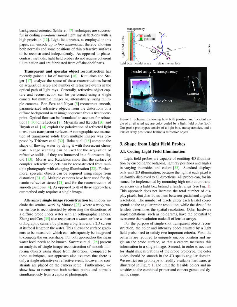
Figure 1. Schematic showing how both position and incident an-gle of a refracted ray are color coded by a light field probe (top).Our probe prototypes consist of a light box, transparencies, and alenslet array positioned behind a refractive object.
3. Shape from Light Field Probes3.1. Coding Light Field Illumination
Light field probes are capable of emitting 4D illumina-tion by encoding the outgoing light ray positions and anglesin varying intensities and colors [33]. Standard displaysonly emit 2D illumination, because the light at each pixel isuniformly displayed to all directions. 4D probes can, for in-stance, be implemented by mounting high-resolution trans-parencies on a light box behind a lenslet array (see Fig. 1).This approach does not increase the total number of dis-play pixels, but distributes them between spatial and angularresolution. The number of pixels under each lenslet corre-sponds to the angular probe resolution, while the size of thelenslets determines the spatial resolution. Other hardwareimplementations, such as holograms, have the potential toovercome the resolution tradeoff of lenslet arrays.
For the purpose of single-shot transparent object recon-struction, the color and intensity codes emitted by a lightfield probe need to satisfy two important criteria. First, thepatterns are required to uniquely encode position and an-gle on the probe surface, so that a camera measures thisinformation in a single image. Second, in order to accountfor slight miscalibrations of the probe prototype, the colorcodes should be smooth in the 4D spatio-angular domain.We restrict our prototype to readily available hardware, asillustrated in Figure 1, and limit the feasible colors and in-tensities to the combined printer and camera gamut and dy-namic range.
The most intuitive coding scheme satisfying the aboverequirements are color gradients. In our implementation,we use red, blue, and green gradients to code the 2D direc-tions and a 1D vertical position, respectively. As demon-strated in Section 3.3, the missing second spatial dimen-sion can be recovered through geometric constraints in post-processing. This encoding is illustrated for a 1D case in Fig-ure 1 (top). Here, the incident angle is coded in a shade ofred and the position on the probe surface is coded in green.
This simple, yet effective coding scheme allows both an-gle and position of light rays to be encoded in observed col-ors and intensities. Without refraction in the optical path,the measured colors at each pixel of a calibrated cameracorrespond to the information predicted by the calibration,but in the presence of refraction these differ. In the follow-ing subsections we show how to reconstruct refractive sur-faces from such measurements. The employed color codesignore the wavelength-dependency of refraction as well asattenuation and scattering caused by the medium.
3.2. Reconstructing Surface Normals
The normal of each surface point imaged by a camerapixel can be computed using Snell’s law: n1 sin θin =n2 sin θout. In our application, we seek the unknown nor-mals given the incoming normalized rays vin, which areknown from camera calibration, and the refracted ray di-rections vout, which are extracted from the imaged probecolor (Fig. 1, top). The absolute angles θin and θout are un-known, but we can compute the difference θd between thetwo as cos θd = vin · vout. For known refractive indices ofthe two media n1 and n2, the angle between incoming rayand surface normal is then given as
θin = tan−1
(n2 sin θd
n2 cos θd − n1
). (1)
Therefore, the surface normal n can be computed inde-pendently for each camera pixel by rotating vin by the an-gle θin. The rotation is performed on the plane spanned byvin and vout, so
n = R (θin,vin × vout) (−vin) , (2)
where R(θ,v) is a rotation matrix defined by angle θaround an axis v.
3.3. Point Cloud Estimation
In order to triangulate absolute 3D surface points foreach camera pixel, we need to determine the intersectionof the lines c + tvin and p + svout. The camera positionc as well as the unrefracted ray directions vin are knownfrom camera calibration and uniquely define a line in 3Dspace. The direction vout is estimated from the observedcolors of the light field probe refracted by an object, how-ever, only a single spatial coordinate is coded by the probe
Cam
era
Imag
eN
orm
al M
ap
Original No Noise Noise, Noise,
Tri
angu
late
d P
osit
ions
Rec
onst
ruct
ed S
urfa
ce
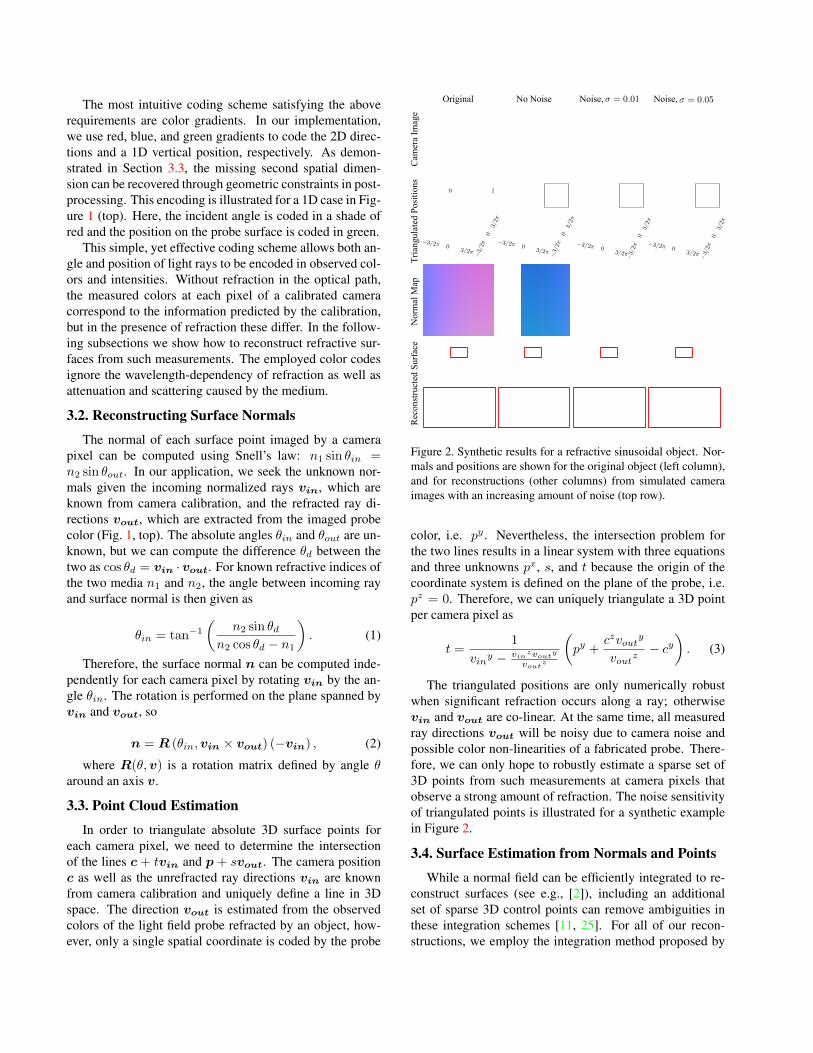
Figure 2. Synthetic results for a refractive sinusoidal object. Nor-mals and positions are shown for the original object (left column),and for reconstructions (other columns) from simulated cameraimages with an increasing amount of noise (top row).
color, i.e. py . Nevertheless, the intersection problem forthe two lines results in a linear system with three equationsand three unknowns px, s, and t because the origin of thecoordinate system is defined on the plane of the probe, i.e.pz = 0. Therefore, we can uniquely triangulate a 3D pointper camera pixel as
t =1
viny − vinzvout
y
voutz
(py +
czvouty
voutz− cy
). (3)
The triangulated positions are only numerically robustwhen significant refraction occurs along a ray; otherwisevin and vout are co-linear. At the same time, all measuredray directions vout will be noisy due to camera noise andpossible color non-linearities of a fabricated probe. There-fore, we can only hope to robustly estimate a sparse set of3D points from such measurements at camera pixels thatobserve a strong amount of refraction. The noise sensitivityof triangulated points is illustrated for a synthetic examplein Figure 2.
3.4. Surface Estimation from Normals and Points
While a normal field can be efficiently integrated to re-construct surfaces (see e.g., [2]), including an additionalset of sparse 3D control points can remove ambiguities inthese integration schemes [11, 25]. For all of our recon-structions, we employ the integration method proposed by
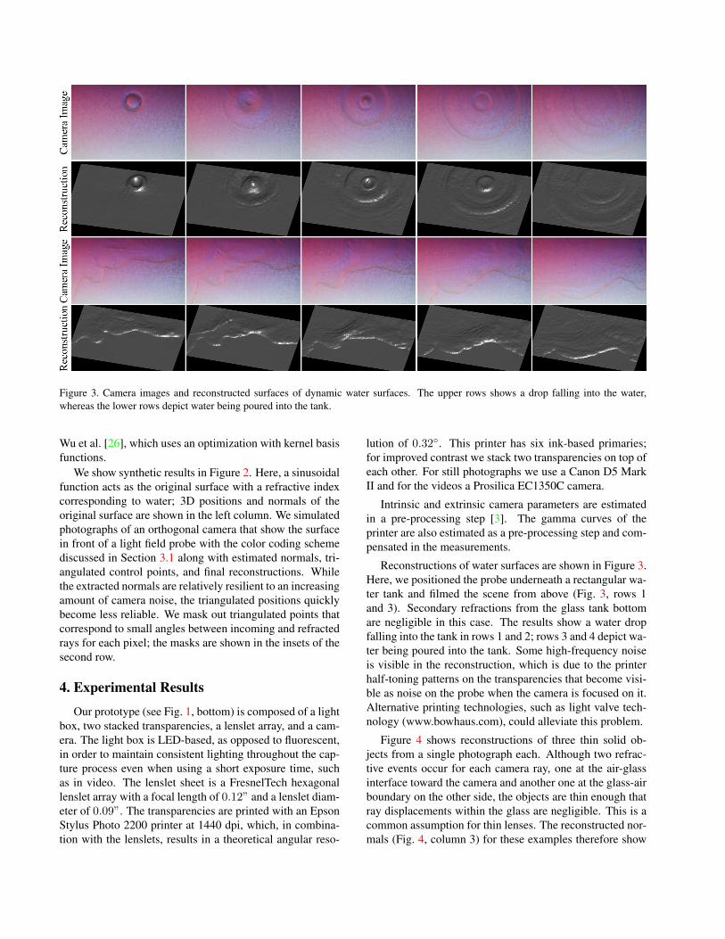
Figure 3. Camera images and reconstructed surfaces of dynamic water surfaces. The upper rows shows a drop falling into the water,whereas the lower rows depict water being poured into the tank.
Wu et al. [26], which uses an optimization with kernel basisfunctions.
We show synthetic results in Figure 2. Here, a sinusoidalfunction acts as the original surface with a refractive indexcorresponding to water; 3D positions and normals of theoriginal surface are shown in the left column. We simulatedphotographs of an orthogonal camera that show the surfacein front of a light field probe with the color coding schemediscussed in Section 3.1 along with estimated normals, tri-angulated control points, and final reconstructions. Whilethe extracted normals are relatively resilient to an increasingamount of camera noise, the triangulated positions quicklybecome less reliable. We mask out triangulated points thatcorrespond to small angles between incoming and refractedrays for each pixel; the masks are shown in the insets of thesecond row.
4. Experimental Results
Our prototype (see Fig. 1, bottom) is composed of a lightbox, two stacked transparencies, a lenslet array, and a cam-era. The light box is LED-based, as opposed to fluorescent,in order to maintain consistent lighting throughout the cap-ture process even when using a short exposure time, suchas in video. The lenslet sheet is a FresnelTech hexagonallenslet array with a focal length of 0.12” and a lenslet diam-eter of 0.09”. The transparencies are printed with an EpsonStylus Photo 2200 printer at 1440 dpi, which, in combina-tion with the lenslets, results in a theoretical angular reso-
lution of 0.32◦. This printer has six ink-based primaries;for improved contrast we stack two transparencies on top ofeach other. For still photographs we use a Canon D5 MarkII and for the videos a Prosilica EC1350C camera.
Intrinsic and extrinsic camera parameters are estimatedin a pre-processing step [3]. The gamma curves of theprinter are also estimated as a pre-processing step and com-pensated in the measurements.
Reconstructions of water surfaces are shown in Figure 3.Here, we positioned the probe underneath a rectangular wa-ter tank and filmed the scene from above (Fig. 3, rows 1and 3). Secondary refractions from the glass tank bottomare negligible in this case. The results show a water dropfalling into the tank in rows 1 and 2; rows 3 and 4 depict wa-ter being poured into the tank. Some high-frequency noiseis visible in the reconstruction, which is due to the printerhalf-toning patterns on the transparencies that become visi-ble as noise on the probe when the camera is focused on it.Alternative printing technologies, such as light valve tech-nology (www.bowhaus.com), could alleviate this problem.
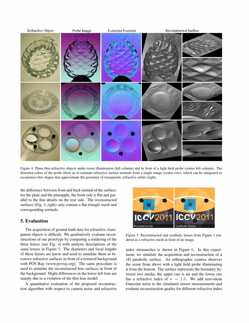
Figure 4 shows reconstructions of three thin solid ob-jects from a single photograph each. Although two refrac-tive events occur for each camera ray, one at the air-glassinterface toward the camera and another one at the glass-airboundary on the other side, the objects are thin enough thatray displacements within the glass are negligible. This is acommon assumption for thin lenses. The reconstructed nor-mals (Fig. 4, column 3) for these examples therefore show
Figure 4. Three thin refractive objects under room illumination (left column) and in front of a light field probe (center left column). Thedistorted colors of the probe allow us to estimate refractive surface normals from a single image (center row), which can be integrated toreconstruct thin shapes that approximate the geometry of transparent, refractive solids (right).
the difference between front and back normal of the surface;for the plate and the pineapple, the front side is flat and par-allel to the fine details on the rear side. The reconstructedsurfaces (Fig. 4, right) only contain a flat triangle mesh andcorresponding normals.
5. Evaluation
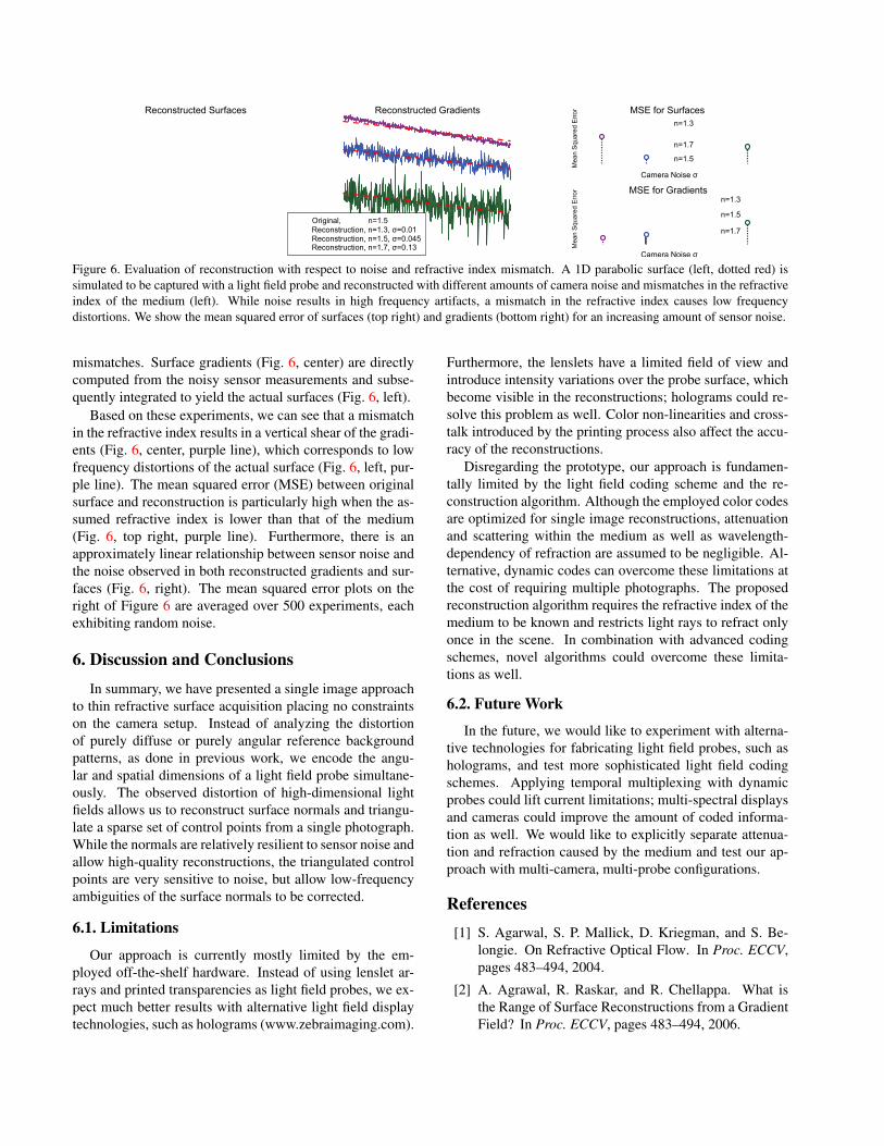
The acquisition of ground truth data for refractive, trans-parent objects is difficult. We qualitatively evaluate recon-structions of our prototype by comparing a rendering of thethree lenses (see Fig. 4) with analytic descriptions of thesame lenses in Figure 5. The diameters and focal lengthsof these lenses are know and used to simulate them as bi-convex refractive surfaces in front of a textured backgroundwith POV-Ray (www.povray.org). The same procedure isused to simulate the reconstructed lens surfaces in front ofthe background. Slight differences in the lower left lens aremainly due to a violation of the thin lens model.
A quantitative evaluation of the proposed reconstruc-tion algorithm with respect to camera noise and refractive
Figure 5. Reconstructed and synthetic lenses from Figure 4 ren-dered as a refractive mesh in front of an image.
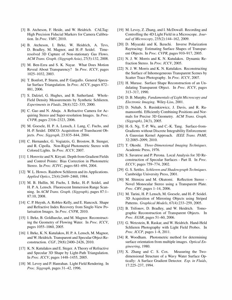
index mismatches is shown in Figure 6. In this experi-ment, we simulate the acquisition and reconstruction of a1D parabolic surface. An orthographic camera observesthe scene from above with a light field probe illuminatingit from the bottom. The surface represents the boundary be-tween two media, the upper one is air and the lower onehas a refractive index of n = 1.5. We add zero-meanGaussian noise to the simulated sensor measurements andevaluate reconstruction quality for different refractive index
Reconstructed Surfaces Reconstructed Gradients MSE for Surfacesn=1.3
Figure 6. Evaluation of reconstruction with respect to noise and refractive index mismatch. A 1D parabolic surface (left, dotted red) issimulated to be captured with a light field probe and reconstructed with different amounts of camera noise and mismatches in the refractiveindex of the medium (left). While noise results in high frequency artifacts, a mismatch in the refractive index causes low frequencydistortions. We show the mean squared error of surfaces (top right) and gradients (bottom right) for an increasing amount of sensor noise.
mismatches. Surface gradients (Fig. 6, center) are directlycomputed from the noisy sensor measurements and subse-quently integrated to yield the actual surfaces (Fig. 6, left).
Based on these experiments, we can see that a mismatchin the refractive index results in a vertical shear of the gradi-ents (Fig. 6, center, purple line), which corresponds to lowfrequency distortions of the actual surface (Fig. 6, left, pur-ple line). The mean squared error (MSE) between originalsurface and reconstruction is particularly high when the as-sumed refractive index is lower than that of the medium(Fig. 6, top right, purple line). Furthermore, there is anapproximately linear relationship between sensor noise andthe noise observed in both reconstructed gradients and sur-faces (Fig. 6, right). The mean squared error plots on theright of Figure 6 are averaged over 500 experiments, eachexhibiting random noise.
6. Discussion and Conclusions
In summary, we have presented a single image approachto thin refractive surface acquisition placing no constraintson the camera setup. Instead of analyzing the distortionof purely diffuse or purely angular reference backgroundpatterns, as done in previous work, we encode the angu-lar and spatial dimensions of a light field probe simultane-ously. The observed distortion of high-dimensional lightfields allows us to reconstruct surface normals and triangu-late a sparse set of control points from a single photograph.While the normals are relatively resilient to sensor noise andallow high-quality reconstructions, the triangulated controlpoints are very sensitive to noise, but allow low-frequencyambiguities of the surface normals to be corrected.
6.1. Limitations
Our approach is currently mostly limited by the em-ployed off-the-shelf hardware. Instead of using lenslet ar-rays and printed transparencies as light field probes, we ex-pect much better results with alternative light field displaytechnologies, such as holograms (www.zebraimaging.com).
Furthermore, the lenslets have a limited field of view andintroduce intensity variations over the probe surface, whichbecome visible in the reconstructions; holograms could re-solve this problem as well. Color non-linearities and cross-talk introduced by the printing process also affect the accu-racy of the reconstructions.
Disregarding the prototype, our approach is fundamen-tally limited by the light field coding scheme and the re-construction algorithm. Although the employed color codesare optimized for single image reconstructions, attenuationand scattering within the medium as well as wavelength-dependency of refraction are assumed to be negligible. Al-ternative, dynamic codes can overcome these limitations atthe cost of requiring multiple photographs. The proposedreconstruction algorithm requires the refractive index of themedium to be known and restricts light rays to refract onlyonce in the scene. In combination with advanced codingschemes, novel algorithms could overcome these limita-tions as well.
6.2. Future Work
In the future, we would like to experiment with alterna-tive technologies for fabricating light field probes, such asholograms, and test more sophisticated light field codingschemes. Applying temporal multiplexing with dynamicprobes could lift current limitations; multi-spectral displaysand cameras could improve the amount of coded informa-tion as well. We would like to explicitly separate attenua-tion and refraction caused by the medium and test our ap-proach with multi-camera, multi-probe configurations.
References[1] S. Agarwal, S. P. Mallick, D. Kriegman, and S. Be-
longie. On Refractive Optical Flow. In Proc. ECCV,pages 483–494, 2004.
[2] A. Agrawal, R. Raskar, and R. Chellappa. What isthe Range of Surface Reconstructions from a GradientField? In Proc. ECCV, pages 483–494, 2006.
[3] B. Atcheson, F. Heide, and W. Heidrich. CALTag:High Precision Fiducial Markers for Camera Calibra-tion. In Proc. VMV, 2010.
[4] B. Atcheson, I. Ihrke, W. Heidrich, A. Tevs,D. Bradley, M. Magnor, and H.-P. Seidel. Time-resolved 3D Capture of Non-stationary Gas Flows.ACM Trans. Graph. (Siggraph Asia), 27(5):132, 2008.
[5] M. Ben-Ezra and S. K. Nayar. What Does MotionReveal About Transparency? In Proc. ICCV, pages1025–1032, 2003.
[6] T. Bonfort, P. Sturm, and P. Gargallo. General Specu-lar Surface Triangulation. In Proc. ACCV, pages 872–881, 2006.
[7] S. Dalziel, G. Hughes, and B. Sutherland. Whole-Field Density Measurements by Synthetic Schlieren.Experiments in Fluids, 28(4):322–335, 2000.
[8] C. Gao and N. Ahuja. A Refractive Camera for Ac-quiring Stereo and Super-resolution Images. In Proc.CVPR, pages 2316–2323, 2006.
[9] M. Goesele, H. P. A. Lensch, J. Lang, C. Fuchs, andH.-P. Seidel. DISCO: Acquisition of Translucent Ob-jects. Proc. Siggraph, 23:835–844, 2004.
[10] C. Hernandez, G. Vogiatzis, G. Brostow, B. Stenger,and R. Cipolla. Non-Rigid Photometric Stereo withColored Lights. In Proc. ICCV, 2007.
[11] I. Horovitz and N. Kiryati. Depth from Gradient Fieldsand Control Points: Bias Correction in PhotometricStereo. In Proc. ICIVC, pages 681–694, 2004.
[12] W. L. Howes. Rainbow Schlieren and its Applications.Applied Optics, 23(4):2449–2460, 1984.
[13] M. B. Hullin, M. Fuchs, I. Ihrke, H.-P. Seidel, andH. P. A. Lensch. Fluorescent Immersion Range Scan-ning. In ACM Trans. Graph. (Siggraph), pages 87:1–87:10, 2008.
[14] C. P. Huynh, A. Robles-Kelly, and E. Hancock. Shapeand Refractive Index Recovery from Single-View Po-larisation Images. In Proc. CVPR, 2010.
[15] I. Ihrke, B. Goldluecke, and M. Magnor. Reconstruct-ing the Geometry of Flowing Water. In Proc. ICCV,pages 1055–1060, 2005.
[16] I. Ihrke, K. N. Kutulakos, H. P. A. Lensch, M. Magnor,and W. Heidrich. Transparent and Specular Object Re-construction. CGF, 29(8):2400–2426, 2010.
[17] K. N. Kutulakos and E. Steger. A Theory of Refractiveand Specular 3D Shape by Light-Path Triangulation.In Proc. ICCV, pages 1448–1455, 2005.
[18] M. Levoy and P. Hanrahan. Light Field Rendering. InProc. Siggraph, pages 31–42, 1996.
[19] M. Levoy, Z. Zhang, and I. McDowall. Recording andControlling the 4D Light Field in a Microscope. Jour-nal of Microscopy, 235(2):144–162, 2009.
[20] D. Miyazaki and K. Ikeuchi. Inverse PolarizationRaytracing: Estimating Surface Shapes of Transpar-ent Objects. In Proc. CVPR, pages 910–917, 2005.
[21] N. J. W. Morris and K. N. Kutulakos. Dynamic Re-fraction Stereo. In Proc. ICCV, 2005.
[22] N. J. W. Morris and K. N. Kutulakos. Reconstructingthe Surface of Inhomogeneous Transparent Scenes byScatter Trace Photography. In Proc. ICCV, 2007.
[23] H. Murase. Surface Shape Reconstruction of an Un-dulating Transparent Object. In Proc. ICCV, pages313–317, 1990.
[24] D. B. Murphy. Fundamentals of Light Microscopy andElectronic Imaging. Wiley-Liss, 2001.
[25] D. Nehab, S. Rusinkiewicz, J. Davis, and R. Ra-mamoorthi. Efficiently Combining Positions and Nor-mals for Precise 3D Geometry. ACM Trans. Graph.(Siggraph), 24(3), 2005.
[26] H.-S. Ng, T.-P. Wu, and C.-K. Tang. Surface-from-Gradients without Discrete Integrability Enforcement:A Gaussian Kernel Approach. IEEE Trans. PAMI,32:2085–2099, 2010.
[27] T. Okoshi. Three-Dimensional Imaging Techniques.Academic Press, 1976.
[28] S. Savarese and P. Perona. Local Analysis for 3D Re-construction of Specular Surfaces - Part II. In Proc.ECCV, pages 759–774, 2002.
[29] G. S. Settles. Schlieren and Shadowgraph Techniques.Cambridge University Press, 2001.
[30] M. Shimizu and M. Okutomi. Reflection Stereo -Novel Monocular Stereo using a Transparent Plate.Proc. CRV, pages 1–14, 2006.
[31] M. Tarini, H. P. Lensch, M. Goesele, and H.-P. Seidel.3D Acquisition of Mirroring Objects using StripedPatterns. Graphical Models, 67(4):233–259, 2005.
[32] B. Trifonov, D. Bradley, and W. Heidrich. Tomo-graphic Reconstruction of Transparent Objects. InProc. EGSR, pages 51–60, 2006.
[33] G. Wetzstein, R. Raskar, and W. Heidrich. Hand-HeldSchlieren Photography with Light Field Probes. InProc. ICCP, pages 1–8, 2011.
[34] R. Woodham. Photometric method for determiningsurface orientation from multiple images. Optical En-gineering, 1980.
[35] X. Zhang and C. S. Cox. Measuring the Two-dimensional Structure of a Wavy Water Surface Op-tically: A Surface Gradient Detector. Exp. in Fluids,17:225–237, 1994.


![Refractive Shape from Light Field Distortion · light field probes have been used to qualitatively visualize refractions caused by macroscopic, transparent solids and liquids [33].](https://static.documents.pub/doc/80x56/611a417a4da9d06d4d5f851c/refractive-shape-from-light-field-light-ield-probes-have-been-used-to-qualitatively.jpg)


