Refractory Tile Installation - Mortar or no Mortar?
Patrick M. Stephan Saint-Gobain Ceramics
1 New Bond Street Worcester, Massachusetts 01615 USA
Christian His and Nathalie Monchalin
Saint Gobain European Ceramics Research Center
Cavaillon, France
Abstract
Some domestic waste incinerators [1] have operated successfully with refractory tile systems for tube protection without using mortar to bond the tiles to the tube walls. Most tile protection systems installed around the world employ a paste of mortar behind the tiles to develop a rigid fixing system, with the presumption that the mortar provides another layer of tube protection behind the tiles. This paper examines the issues behind these approaches to tube wall protection and propose some guidelines for the use of refractories in these systems.
Introduction
Refractory materials are used on boiler tube walls to protect the tube steel from corrosion, particulate erosion, thermal damage and solid waste abrasion. In waste-to-energy facilities, refractory usage on tube walls is quite varied, ranging from cast aluminum oxide-based cements having low heat transfer capability, to engineered silicon carbide- based cements and special shapes providing higher heat transfer characteristics with longer-term performance and maintenance benefits.
Refractory tube wall protection concepts have evolved over the years with new design concepts and improvements in installation practices around the world. Most state-of-the-art refractory systems now employ silicon carbide gunned, cast or rammed cements or "tile systems", with metal anchors for attachment of tiles to the tube walls.
Conventional engineering in the development of refractory tile systems has dictated that a ceramic mortar, generally consisting of fine silicon carbide grains suspended in a calcium aluminate cement or phosphate chemical matrix, is essential for adhering
129
tiles to boiler tube walls while enhancing heat flow between the tiles and tube walls. Silicon carbide refractory tiles are pressed or cast during manufacturing and fired at high temperatures sufficient to achieve a bonded shape with good mechanical and thermal properties. Mortars are generally mixed with water and are only cured, or fired, to the temperatures they are subjected to in operation on boiler tube walls. Therefore, the heat transfer capability of mortar is lower than that for dense, bonded tile shapes, which indicates that the mortar layer between refractory tiles and tube walls should be as thin as possible to maximize heat transfer [2], yet provide a full contact surface.
Considering the interest of waste-to-energy facility operators to minimize maintenance outage time and reduce maintenance costs, a study was conducted to evaluate a refractory tube wall protection system using tiles without mortar that could be installed quickly and repaired easily. Corrosion protection, heat transfer characteristics and performance over time compared to conventional tile systems using mortar were evaluated.
A commercial waste-to-energy facility in Jamestown, NY was selected for the initial experiments. The unit has a nominal capacity of 330 tons per day and normally operates at full load. Gas temperatures in the area of the tile systems were expected to be in the range of 1100-1200C, while the steam saturation temperature in the boiler tubes was expected to be in the range of 260C.
Following an analysis of the initial results from the tile system test in Jamestown, a second test facility in Wuppertal, Germany was selected for further testing of an improved tile system concept.
A study of bolted tiles was previously conducted at the Jamestown facility and results were reported [3] showing the influence of expansion and resultant networking of tiles attached to the boiler tube walls. The study started with the intent of designing a tile system that would accommodate thermal expansion stresses while reducing installation costs, keeping in mind the need to adequately protect the boiler tubes from high temperatures and corrosive gases.
In each study, tiles at several locations in the tile arrays were prepared for insertion of thermocouples and/or motion sensors. A data logging system was set up to remotely transmit temperature and tile motion data to a computer file that could be analyzed to monitor the systems.
Thermo-mechanical models using ANSYS were developed to analyze tile temperatures under various assumptions of temperature distributions, with or without mortar between the tiles and tube walls.
Tile System Description
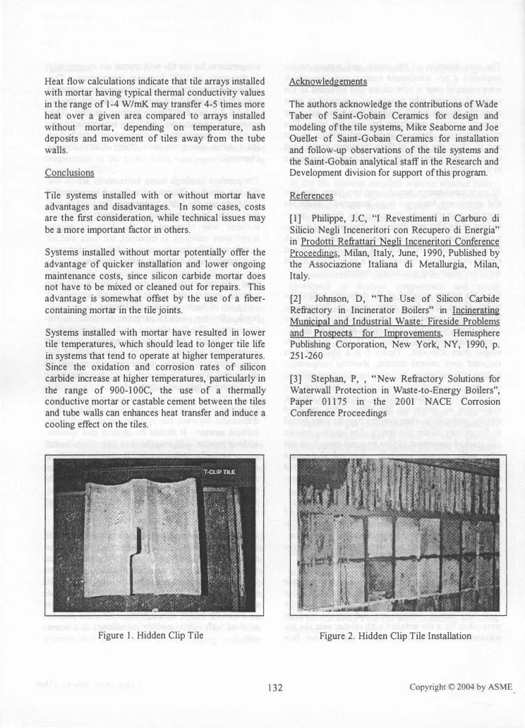
Nitride-bonded silicon carbide compositions were used for the tile panel tests. The tile shape used for these studies (Figure 1) employs a "hidden clip" for attachment to the tube wall membrane through a hidden stud, washer and nut assembly. Hidden clip tile panels installed on tube walls result in very smooth wall surfaces, with mortar (or expansion) joints between the tiles, as shown in Figure 2. In most commercial installations, these tile systems have demonstrated significantly better slagging resistance
130
than monolithic cements and have reduced long-term maintenance costs.
The stud, washer and nut are generally made of 316 stainless steel for corrosion resistance at reasonable cost. A fine-grained silicon carbide coating was applied to the boiler tubes after sandblasting and cleaning to provide an additional corrosion barrier for tube protection (Figure 3).
In the tile systems installed with or without silicon carbide mortar, a high-temperature fiber-containing compound was applied along the edges to accommodate expansion and seal the joints from gas penetration.
ANSYS Model Results
Thermo-mechanical models based on ANSYS were developed to analyze temperature and stress distributions in tiles for comparison to the field test results. The models were iteratively improved based on the field test results by varying assumptions about temperature distributions at various locations in the boilers and changing convective heat transfer coefficients.
The high thermal conductivity of silicon carbide tiles (@ 15-25 W/mK, similar to stainless steel) imparts relatively low thermal gradients in the tiles, resulting in a "cooling effect" on the hot face of the tiles (compared to gas temperature). Maximum principal stresses were calculated at nearly 90 MPa, although typical stress levels throughout the tiles were much lower.
Early attempts to model and predict the differences between tiles installed with and without mortar yielded results that did not seem possible, due to the difficulty in modeling radiative versus conductive heat transfer.
Experimental Tile System Results,
In the initial Jamestown trials using bolted tiles, the networking effect of rigidly attached tiles having mortar behind the tiles resulted in large field stresses in the tile arrays. Figure 4 shows how large areas of tiles bowed away from the wall, stretching the metal studs by 10 mm or more.
The next iteration of tile shape and system design employed a pin attachment system and tiles which were centered over a tube crown and extended to the center of adjacent tube crowns, as compared to most other tile designs which covered two tubes and were centered over the membrane between the tubes. This tile system was designed to be used without mortar and to allow the tiles to float, to some extent, and accommodate some of the thermal expansion stresses in the system.
At each maintenance period over two years, the tiles and attachment hardware were inspected. Some tile cracking over the tube crown in the thinnest crosssection of the tiles was observed (Figure 5), as well as some bending of the attachment hardware, which made maintenance more difficult. This tile shape and system design were replaced with a more conventional modified hidden clip attachment system.
For a tile system installed on the right side wall of the boiler above the feed table area at Jamestown, thermocouple readings on the hot face of the tiles ranged from 600-800C, with peaks as high as 1000C. Temperature readings on the cold face of the tiles ranged from 350-500C. Figure 6 is a chart for data recorded over several months, showing temperature swings with variations in boiler operating conditions, including downtime for a maintenance outage at two months into the chart. These temperature swings, sometimes as much as 200-300C, often occurred rapidly, particularly when overfire burners were cycled in the vicinity of the tile arrays. The motion sensors also tracked movement of tiles into and away from the tube walls. It was generally observed that rapid temperature swings resulted in the most significant tile movement and, presumably, the highest thermomechanical stresses in the tiles.
Tiles installed without mortar were generally observed to have temperature distributions in the range of 50-100C higher than those for tiles installed with mortar. This was confirmed again by analysis of the Wuppertal temperature results.
Temperature and motion readings for a thermocouple embedded near the hot face in a tile installed without mortar at Wuppertal is shown in Figure 7. During the same time period, temperature and motion readings were taken for a tile installed with mortar near the tile without mortar. Figure 8 shows that the hot face
131
temperatures for the tile with mortar are consistently in the range of 100C lower in temperature. The difference in movement of the tiles is quite apparent, with readings of 0.7-0.8 mm for the tile with mortar and 1.8-2.1 mm for the tile without mortar. This amount of motion away from the tube walls is not significant compared to readings taken in the bolted tile systems where the networking of stresses was observed.
Temperature readings taken horizontally across the tile test panel at Wuppertal reflected temperatures that were usually 100C higher near the burners and feed table. More cracking and pitting of the tile surfaces was observed in the area of higher temperature readings, as expected, but there was no significant difference in cracking behavior between tiles installed with mortar or without mortar.
One concern related to the installation of tiles without mortar was for the potential accelerated corrosion of the boiler tubes if tiles were to move or break, allowing gases to penetrate the joints in the tile system. The fine silicon carbide coating applied to the boiler tubes was examined at each maintenance interval and at the conclusion of the tests. After two years at Jamestown and one year at Wuppertal (Figure 9), no significant degradation of the coating or tubes was observed.
Consideration should be given to heat flow differences between tile systems installed with and without mortar. It should be obvious that systems without mortar will transfer less heat from boiler gases to boiler tubes under the same operating conditions. This is not neither good nor bad. In the case of a boiler that needs to be operated at high thermal efficiency and generate as much steam as possible, silicon carbide tiles installed with mortar are recommended.
However, some operators need to tailor the vertical thermal profiles in their boilers to meet environmental regulations, such as those that require a specific residence time of gases at a temperature which destroys dioxins. The use of tiles without mortar in various zones may allow the operator to adjust the heat flow and, thus, the temperature profile in the boiler, although the same effect may be attained with silicon carbide monolithics at a lower cost.
Heat flow calculations indicate that tile arrays installed with mortar having typical thermal conductivity values in the range of 1-4 W/mK may transfer 4-5 times more heat over a given area compared to arrays installed without mortar, depending on temperature, ash deposits and movement of tiles away from the tube walls.
Conclusions
Tile systems installed with or without mortar have advantages and disadvantages. In some cases, costs are the first consideration, while technical issues may be a more important factor in others.
Systems installed without mortar potentially offer the advantage of quicker installation and lower ongoing maintenance costs, since silicon carbide mortar does not have to be mixed or cleaned out for repairs. This advantage is somewhat offset by the use of a fibercontaining mortar in the tile joints.
Systems installed with mortar have resulted in lower tile temperatures, which should lead to longer tile life in systems that tend to operate at higher temperatures. Since the oxidation and corrosion rates of silicon carbide increase at higher temperatures, particularly in the range of 900-100C, the use of a thermally conductive mortar or castable cement between the tiles and tube walls can enhances heat transfer and induce a cooling effect on the tiles.
Figure 1. Hidden Clip Tile
132
Acknowledgements
The authors acknowledge the contributions of Wade Taber of Saint-Gobain Ceramics for design and modeling of the tile systems, Mike Seaborne and Joe Ouellet of Saint-Gobain Ceramics for installation and follow-up observations of the tile systems and the Saint-Gobain analytical staff in the Research and Development division for support of this program.
References
[ 1] Philippe, J. C, "I Revestimenti in Carburo di Silicio Negli Inceneritori con Recupero di Energia" in Prodotti Refrattari Negli Inceneritori Conference Proceedings, Milan, Italy, June, 1990, Published by the Associazione Italiana di Metallurgia, Milan, Italy.
[2] Johnson, D, "The Use of Silicon Carbide Refractory in Incinerator Boilers" in Incinerating Municipal and Industrial Waste: Fireside Problems and Prospects for Improvements, Hemisphere Publishing Corporation, New York, NY, 1990, p. 251-260
[3] Stephan, P, , "New Refractory Solutions for Waterwall Protection in Waste-to-Energy Boilers", Paper 0 1 175 in the 2001 NACE Corrosion Conference Proceedings