Refrigerant Containment Study Date of publication: September 2015 Conducted for ADEME by Cemafroid and IRSTEA Contract No. 1481C0048 Prepared by: Eric Devin / Thomas Michineau / Florence Moulins / Frédéric Vannson / Laurence Fournaison / Romuald Hunlede / Denis Leducq / Anthony Delahaye Technical coordination: François Heyndrickx – AFCE, Hélène Riviere-Kaluc – Service Entreprise et EcoTechnologies, ADEME, Angers [ FINAL REPORT
Transcript
Refrigerant Containment Study
Date of publication: September 2015
Conducted for ADEME by Cemafroid and IRSTEA
Contract No. 1481C0048
Prepared by: Eric Devin / Thomas Michineau / Florence Moulins / Frédéric Vannson / Laurence
Fournaison / Romuald Hunlede / Denis Leducq / Anthony Delahaye
Technical coordination: François Heyndrickx – AFCE, Hélène Riviere-Kaluc – Service Entreprise et
EcoTechnologies, ADEME, Angers
[
FINAL REPORT
Refrigerating Plant Containment Study Page 2 of 77
Acknowledgements
We would like to express our sincere gratitude to the members of the Steering Committee:
Hélène RIVIERE-KALUC, Service Entreprise et Écotechnologies, ADEME
François HEYNDRICKX (Chief Executive, Alliance Froid Climatisation Environnement)
Régis LEPORTIER, Laurent GUEGAN, Olivier ROBERT (Members of the AFCE Board of Directors)
We also wish to thank all the professionals contacted for the study, especially those we met during our
on-site visits and those who took the time to fill in the online survey.
Copyright
Any representation or reproduction, in whole or in part, made without the consent of the authors or
their successors or assigns is wrongful under the Intellectual Property Code (Art. L 122-4) and
constitutes an infringement sanctioned by the Penal Code. Only the following (Art. 122-5) are
permitted: copies or reproductions which are strictly for the purpose of the private use of the person
making the copy and not intended for collective use, and reviews and short quotations which are
justified by the critical, educational, or informative nature of the work in which they are incorporated,
on condition that the provisions of Articles L122-10 to L122-12 of the said Code relating to
reprographic reproduction are complied with.
Refrigerating Plant Containment Study Page 3 of 77
SCOPE OF THE DOCUMENT ........................................................................................................................................ 8
BENEFIT TO READERS ................................................................................................................................................ 8
1. BACKGROUND OF THE STUDY ................................................................................................................ 10
1.1. PURPOSE OF THE REPORT ........................................................................................................................... 10
1.2. OVERVIEW OF THE ORGANISATIONS WHO CARRIED OUT THE STUDY ..................................................................... 10
2. METHODOLOGICAL APPROACH OF STUDY ............................................................................................. 11
2.1. SEGMENTATION BY LINE OF ACTIVITY AND BY REFRIGERATION SYSTEM ................................................................. 11
2.2. FORMAT OF BIBLIOGRAPHIC REFERENCE SUMMARY SHEETS .............................................................................. 12
5.2. NATURE OF THE PLANTS ............................................................................................................................. 39
5.3. DATA COLLECTION .................................................................................................................................... 40
6. ON-SITE ASSESSMENT OF EQUIPMENT OR FACILITY .............................................................................. 42
7.5. PUBLIC AUTHORITIES ................................................................................................................................. 53
9. LIST OF TABLES....................................................................................................................................... 58
Refrigerating Plant Containment Study Page 4 of 77
10. LIST OF FIGURES ................................................................................................................................ 59
Refrigerating Plant Containment Study Page 9 of 77
Abstract Refrigerant leakages have an important direct impact on climate change due to their greenhouse
gaseous properties and also an indirect impact because of the energy efficiency reduction of that
equipment.
Cemafroid and Irstea, at the request of AFCE (Alliance Froid Climatisation Environnement
http://www.afce.asso.fr/) were involved from September 2014 till May 2015 in a research program in
order to develop a guidance document to help end-users or maintenance companies to detect and to
minimize refrigerant leaks.
This study was based on a general literature review in order to list best practices for a large scope of
equipment. A general approach to estimate leaks was developed in order to identify in real conditions,
the precise origins of leakages. This approach includes an online questionnaire sent to more than 500
equipment owners/installers to collect refrigerant and maintenance data. This approach was
completed by on-site visits to more than 20 different installations. The representative scope of
equipment included in this study (HVAC, refrigeration equipment, etc.) have been evaluated in order to
identify which component is commonly responsible for refrigerant losses or which procedure of
containment has to be promoted.
This report presents the result of this study which is particularly important in the field of refrigerant
especially HFC ones where the new regulation (F-Gas in Europe) reinforces all initiatives to limit
uncontrolled emission of the greenhouse gas.
Refrigerating Plant Containment Study Page 10 of 77
1. Background of the Study
1.1. Purpose of the Report AFCE is an association governed by the French law of 1901 which promotes the responsible use of
refrigerants. As such, the study reviews the regulatory work relating to HFCs and regarding all
refrigeration techniques in general.
Refrigerants are essential to the operation of refrigerating and air-conditioning plants. Leakage rates
for many applications are little known, other than by their owners. Whereas factory-charged equipment
are tested by the manufacturer and presumed to be leak-tight, plants which are assembled and then
charged onsite, on the other hand, may be subject to leakage rates greater than 30% per year. A
recent study has shown that inherent leak-tightness of the components cannot be questioned but that
the suitable containment of a plant depends on how the components are implemented, and then how
the facility is operated, and its degree of obsolescence.
The study focuses on the French territory and on plants charged with halogenated fluids (HCFC, HFC)
but also so-called natural fluids1 (CO2, Ammonia, and hydrocarbons). Factory-charged equipment are
also reviewed.
1.2. Overview of the organisations who carried out the study
The consortium who initiated the study consists of Cemafroid, a centre of expertise in the cold chain,
and IRSTEA, a research centre in refrigeration engineering.
Both entities have complementary skills. Their personnel have extensive knowledge of refrigeration
systems, a world reputation on refrigerants, and a network of relations with all the parties involved:
Ministries, the European Commission, chemical engineering companies specialised in refrigerants,
major air-conditioning and refrigeration companies, large user companies, and professional trade
unions.
Furthermore, the lines of activity of these organisations are not related to the manufacturing and
marketing activities of the technologies reviewed by the study, thus ensuring that the state of the art
techniques are assessed in an impartial and independent way. The experts who took part in the study
are listed in Appendix 6.
1 So-called « Natural Refrigerants» are described as such since they have no impact on the Environment but
they remain chemically synthetized compounds.
Refrigerating Plant Containment Study Page 11 of 77
2. Methodological Approach of Study
2.1. Segmentation by line of activity and by refrigeration system The overall refrigeration and air-conditioning applications can be broken down into 7 main fields of
application:
Domestic refrigeration;
Commercial refrigeration;
Refrigerated transport;
Industrial refrigeration (food industry);
Air-conditioning systems;
Heat pumps and
Mobile air-conditioning.
Within these fields, various types of plants or equipment are used, which can be distinguished in that
they use different technologies (e.g., centrifugal compressor, displacement compressor), different
system structures (direct expansion system, indirect system including one, or even two cooling loops),
and different refrigerants.
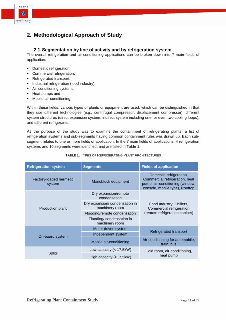
As the purpose of the study was to examine the containment of refrigerating plants, a list of
refrigeration systems and sub-segments having common containment rules was drawn up. Each sub-
segment relates to one or more fields of application. In the 7 main fields of applications, 4 refrigeration
systems and 10 segments were identified, and are listed in Table 1.
TABLE 1. TYPES OF REFRIGERATING PLANT ARCHITECTURES
Refrigeration system Segments Fields of application
Refrigerating Plant Containment Study Page 12 of 77
2.2. Format of Bibliographic Reference Summary Sheets
Bibliographic references are taken from the databases of Cemafroid and Irstea, and scientific
databases such as ScienceDirect (ELSEVIER) or Fridoc (International Institute of Refrigeration).
Title Document Title
Date Date of publication Sheet no.: 1
Author Affiliation:
Nature: Type of document: scientific paper, technical article, study report, , etc.
Source: Publishers
Summary: Abstract of document
Field of Application As defined in the segmentation
Refrigerant: Refrigerant’s ASHRAE classification if available; if not, refrigerant family
Type of machine:
Hermetic system:
Recommendations
Notes
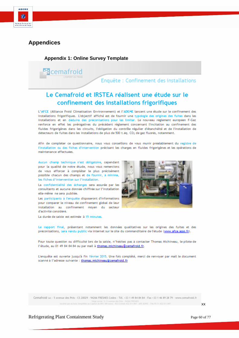
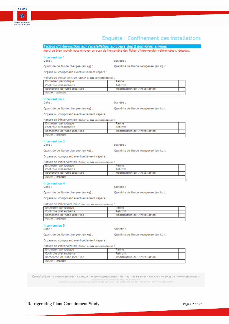
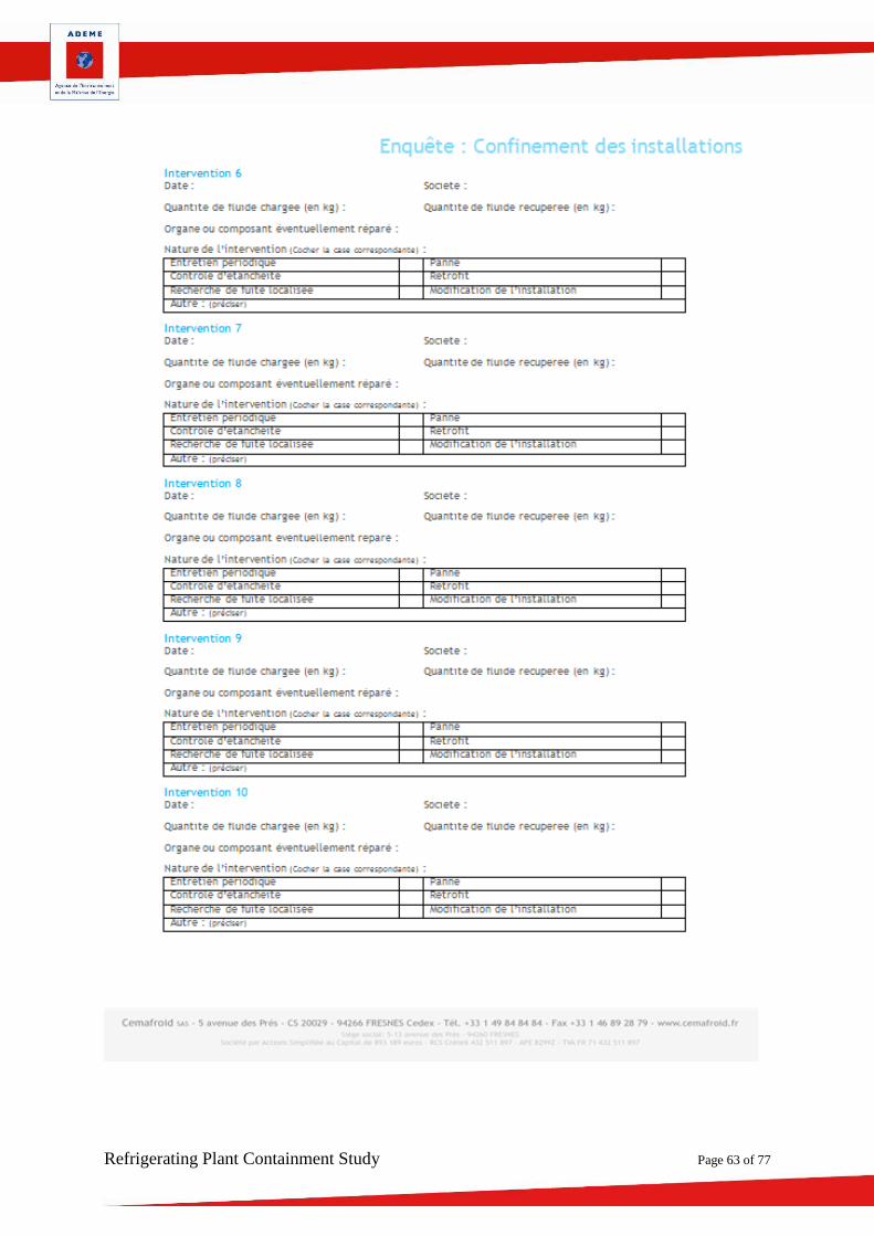
2.3. Online Survey
An online survey (see template in Appendix 1) was conducted starting in October 2014 among 500
participants to identify the causes of leakage according to the field of application and the refrigeration
system as defined in the segmentation.
To preserve the representativeness of the survey, special care was taken in the selection of facilities
according to the line of activity and the refrigeration system.
The authors of the study also offered the participants strict confidentiality agreements on the data
supplied.
2.4. Inspection Sheet
To supplement the information obtained during the online survey, Cemafroid selected a number of
plants for on-site visits. The visits were performed by auditors having refrigeration expertise. The
template for the visit report can be found in Appendix 2.
During these visits the technical documentation of the facility was examined together with the job
sheets. Where possible, experts examined the maintenance contract to check the inspection
frequency and the points periodically checked.
Refrigerating Plant Containment Study Page 13 of 77
3. Bibliography and Overview of the Current Situation
3.1. Nature of the Documents Reviewed The full list of the documents reviewed is given for reference.
3.1.1. Document Contents The documents reviewed relate to various topics:
Leakage rate calculation method;
Leakage rate data;
Leakage rate measurement method;
Good practice guide;
Recommendations;
Environmental impact.
The breakdown is given in Table 2.
TABLE 2. TOPICS ADDRESSED IN THE DOCUMENTS REVIEWED
Sheet no.
Leakage rate calculation
method
Leakage rate data
Measuring method
Good practice guide
Recommendations Environmental
impact
1 X X X
X X
2 X X X
4 X X X X X
5 X X
6 X
7 X
8 X X X
9 X X
10
11 X X
12 X X X X
14
X X
15 X
X
16
X
17 X X X
18 X
19 X X X
20 X
21
X
Refrigerating Plant Containment Study Page 14 of 77
Sheet no.
Leakage rate calculation
method
Leakage rate data
Measuring method
Good practice guide
Recommendations Environmental
impact
22 X X
23 X X X
24 X
25 X X X
26
X
27 X X X X X
28 X X X
29
X
30 X X
31 X
32
33 X X
34 X X
35 X X X X
36 X X
37 X X
38 X
X X
39
X X
40 X X X
41
X
42 X X X
43 X X
44 X
X
45 X X
46 X
X
47 X X
48
49 X
50
51 X X X
52 X
X
Total 19 20 8 11 21 22
Refrigerating Plant Containment Study Page 15 of 77
3.1.2. Typology
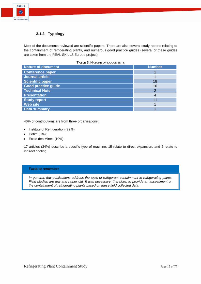
Most of the documents reviewed are scientific papers. There are also several study reports relating to
the containment of refrigerating plants, and numerous good practice guides (several of these guides
are taken from the REAL SKILLS Europe project).
TABLE 3. NATURE OF DOCUMENTS
Nature of document Number
Conference paper 1
Journal article 1
Scientific paper 18
Good practice guide 10
Technical Note 2
Presentation 4
Study report 11
Web site 1
Data summary 1
40% of contributions are from three organisations:
Institute of Refrigeration (22%);
Cetim (8%);
Ecole des Mines (10%).
17 articles (34%) describe a specific type of machine, 15 relate to direct expansion, and 2 relate to
indirect cooling.
Facts to remember
In general, few publications address the topic of refrigerant containment in refrigerating plants. Field studies are few and rather old. It was necessary, therefore, to provide an assessment on the containment of refrigerating plants based on these field collected data.
Refrigerating Plant Containment Study Page 16 of 77
3.1.3. Date of Publication A significant increase in publications on the topic of containment was observed after F-Gas (2006) was issued, intensified by the valorisation of the REALZero(2009) and REALSkills (2011) projects.
FIGURE 1: BREAKDOWN OF DOCUMENTS BY DATE OF PUBLICATION
3.2. Leakage Theory & Main Detection Methods This section describes the theoretical elements taken from the publications referred to in this report.
3.2.1. Leakage Types A leak or leakage is the transfer of a fluid (gas or liquid). There are 2 types of leakage:
Permeation leakage: this is a leak that occurs through a porous wall;
Interfacial leakage: this is a leak due to a passage (a crack, a scratch, a foreign body creating a
passage, under-tightening of 2 assembled components, etc.).
In general, permeation leakage is neglected in comparison to interfacial leakage, because the
migration of a fluid is often much slower, except for leaks in hoses, which often have elastomer walls
that may become porous with time.
3.2.2. Main Indirect Methods of Leak Detection Article 7 of European Regulation no. 1516/2007 proposes a list of indirect methods:
measurement by pressure drop;
measurement by pressure build-up;
monitoring of the plant’s operating parameters;
use of an atmosphere detector.
These methods can identify the presence of leakage, without locating it.
Measurement by pressure drop
In order to determine the overall leak-tightness of the system, prior to being evacuated and charged
the plant is pressurised to maximum operating pressure using an inert gas, commonly nitrogen. The
Refrigerating Plant Containment Study Page 17 of 77
changes in pressures are monitored, but also the changes in temperature. In fact, a change in
temperature may influence the gas pressure, and therefore lead to an incorrect result.
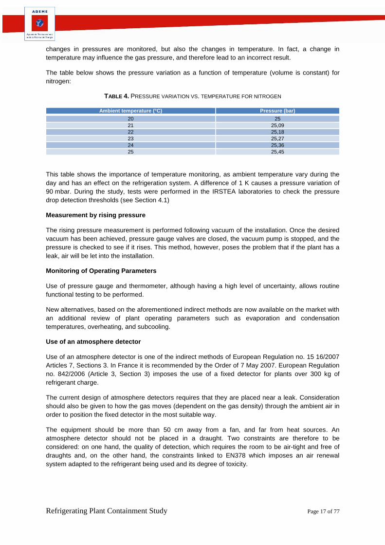
The table below shows the pressure variation as a function of temperature (volume is constant) for
nitrogen:
TABLE 4. PRESSURE VARIATION VS. TEMPERATURE FOR NITROGEN
Ambient temperature (°C) Pressure (bar)
20 25
21 25,09
22 25,18
23 25,27
24 25,36
25 25,45
This table shows the importance of temperature monitoring, as ambient temperature vary during the
day and has an effect on the refrigeration system. A difference of 1 K causes a pressure variation of
90 mbar. During the study, tests were performed in the IRSTEA laboratories to check the pressure
drop detection thresholds (see Section 4.1)
Measurement by rising pressure
The rising pressure measurement is performed following vacuum of the installation. Once the desired
vacuum has been achieved, pressure gauge valves are closed, the vacuum pump is stopped, and the
pressure is checked to see if it rises. This method, however, poses the problem that if the plant has a
leak, air will be let into the installation.
Monitoring of Operating Parameters
Use of pressure gauge and thermometer, although having a high level of uncertainty, allows routine
functional testing to be performed.
New alternatives, based on the aforementioned indirect methods are now available on the market with
an additional review of plant operating parameters such as evaporation and condensation
temperatures, overheating, and subcooling.
Use of an atmosphere detector
Use of an atmosphere detector is one of the indirect methods of European Regulation no. 15 16/2007
Articles 7, Sections 3. In France it is recommended by the Order of 7 May 2007. European Regulation
no. 842/2006 (Article 3, Section 3) imposes the use of a fixed detector for plants over 300 kg of
refrigerant charge.
The current design of atmosphere detectors requires that they are placed near a leak. Consideration
should also be given to how the gas moves (dependent on the gas density) through the ambient air in
order to position the fixed detector in the most suitable way.
The equipment should be more than 50 cm away from a fan, and far from heat sources. An
atmosphere detector should not be placed in a draught. Two constraints are therefore to be
considered: on one hand, the quality of detection, which requires the room to be air-tight and free of
draughts and, on the other hand, the constraints linked to EN378 which imposes an air renewal
system adapted to the refrigerant being used and its degree of toxicity.
Refrigerating Plant Containment Study Page 18 of 77
3.2.3. Main Direct Methods of Leak Detection There are numerous methods of locating a leak. Some can be used to perform a measurement, and
therefore to estimate the local leakage level, others to indicate whether a threshold, either
predetermined or estimated, has been exceeded (in the range of 5 g/yr.). During the study, tests were
performed in the Cemafroid laboratories to check the detection thresholds of leak detectors (see
Section 4.2)
The European F-Gas regulation refers to the following direct methods: use of gas detection devices,
fluorescent liquids more readily visible with UV rays, colorants, foaming solutions or soapy water.
These methods are associated with different types of techniques or apparatus:
- Measuring detector: a complex, costly apparatus which is used to locate, detect and estimate
the value of the leak detected;
- Electronic detector: an apparatus that detects and locates a leak by showing whether a
determined leakage value has been exceeded;
- Foaming product or soapy water, which are used to locate a major leak;
- Fluorescent fluid, which is used to locate a leak by observation of a visible spot using a UV
lamp.
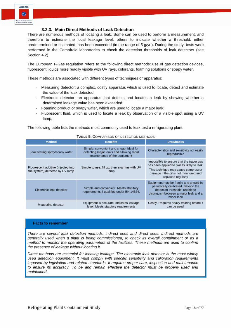
The following table lists the methods most commonly used to leak test a refrigerating plant.
TABLE 5. COMPARISON OF DETECTION METHODS
Method Benefits Drawbacks
Leak testing spray/soapy water Simple, convenient and cheap. Ideal for detecting major leaks and allowing rapid
maintenance of the equipment
Characteristics and sensitivity not easily reproducible
Fluorescent additive (injected into the system) detected by UV lamp
Simple to use: fill up, then examine with UV lamp
Impossible to ensure that the tracer gas has been applied to places likely to leak.
This technique may cause compressor damage if the oil is not monitored and
replaced regularly
Electronic leak detector Simple and convenient. Meets statutory
requirements if qualified under EN 14624.
Equipment may be fragile and should be periodically calibrated. Beyond the
detection threshold, unable to distinguish between a major leak and a
minor leak
Measuring detector Equipment is accurate. Indicates leakage
level. Meets statutory requirements Costly. Requires heavy training before it
can be used.
Facts to remember
There are several leak detection methods, indirect ones and direct ones. Indirect methods are generally used when a plant is being commissioned, to check its overall containment or as a method to monitor the operating parameters of the facilities. These methods are used to confirm the presence of leakage without locating it.
Direct methods are essential for locating leakage. The electronic leak detector is the most widely used detection equipment. It must comply with specific sensitivity and calibration requirements imposed by legislation and related standards. It requires proper care, inspection and maintenance to ensure its accuracy. To be and remain effective the detector must be properly used and maintained.
Refrigerating Plant Containment Study Page 19 of 77
3.3. Summary of the available results on the environmental impact of leakage
3.3.1. Refrigerant Bank Document [52] provides an overview of the global bank and emissions of refrigerants. HFCs are
shown to dominate the market with 75% of the bank (including 40% for R134a).
FIGURE 2. DISTRIBUTION OF REFRIGERANTS FORMING THE REFRIGERANT BANK OVER METROPOLITAN FRANCE.
FIGURE 3. DISTRIBUTION OF THE REFRIGERANT BANK BY SECTOR
Refrigerating Plant Containment Study Page 20 of 77
3.3.2. Direct Emissions Document [52] provides fugitive emission rates by field and sub-sector.
Field Sub-Sectors Average Charge Fugitive Emission Rate
Domestic refrigeration Refrigerators 46 g 0.01%
Freezers and combos 60 g 0.01%
Commercial refrigeration
Supermarket 0.2 kg/m2 30%
Hypermarket 0.14 kg/m2 35%
Hermetic units for small businesses 0.3 to 3kg 1%
Condensing units found in small businesses 2 to 20kg 15%
Refrigerated transport Driving pulley units used in road transport 1.6kg 20%
Self-contained units 6.5kg 11%
Food Industry 100 kg to a few tons 15%
Water Chillers Small capacity 0.3 kg/kW 10%
Medium and high power 0.2 kg/kW 5%
Air-conditioning
Individual, mobile, window, or console type 0.5 to 1kg 2 to 5%
Individual, small capacity split 1.5 kg 5%
Self-contained (VRF) 9kg 10%
Self-contained (Rooftop, medium/high power split) 5 to 30kg 6 to 10%
Heat pumps Residential 2.5 to 15kg 2 to 5%
TABLE 6. FUGITIVE EMISSION RATES BY FIELD AND SUB-SECTOR
This table is taken from Inventaires des Emissions des fluides frigorigènes FRANCE et DOM COM Année 2012, Armines, ERIE, Décembre 2013
(Inventory of Refrigerant Emissions from FRANCE and overseas territories in Year 2012, published in December 2013)
Refrigerating Plant Containment Study Page 21 of 77
3.3.3. Indirect Emissions In the event of leakage, impact on the greenhouse effect is due not only to the emission of refrigerants
but also to the indirect effect of the facility’s lower performance. The proportion of the refrigeration
machine’s indirect effect, therefore, is substantial when leakage occurs. However, a less than 20%
variation in charge has little impact on energy consumption. Higher than this, overconsumption is
significant [26].
FIGURE 4 REFRIGERATING CAPACITY VARIATION VS. FLUID CHARGE
On the above Figure, it is shown that for a 25% loss in charge, the capacity is decreased by 14%, and
for a loss of 50%, a 40% decrease in refrigerating capacity can be observed.
It should be noted that the average emission in CO2 eq. of a heat pump in the UK is estimated to be
greater than or equal to that of a fuel combustion heating solution [6].
Facts to remember
The global leakage rate for all refrigerants appears to be in the range of 17%. Leakage rate data vary widely according to the documents reviewed, especially for commercial refrigeration, where leakage rates vary from 6.5% to 30% depending on the publications. When leakage occurs, impact on the greenhouse effect is due not only to the emission of refrigerants but also to the indirect effect of the facility’s lower performance.
Refrigerating Plant Containment Study Page 22 of 77
3.4. Summary of existing guidelines and recommendations
3.4.1. Main Causes of Leakage The level of leakage depends on the refrigeration technology. Direct expansion systems are more
susceptible to leakage.
Heat stresses (evaporator defrosting period) are the cause of major fatigue and increased risk of
leakage at evaporator return bends.
Mechanical stresses are high in refrigerating plants. Liquid hammering or repeated vibration may
cause pipe ruptures leading to severe leakage.
3.4.2. Aggravating Factors The detection systems in place do not always warn the plant maintainer, any rapid onsite response
thus being delayed.
The funds allocated to maintenance are not always sufficient to provide quality maintenance.
3.4.3. Main Leaking Components in a Refrigerating Plant By definition there is no such thing as absolute dynamic sealing: it is an ideal to which technology is
aspiring.
Many documents agree with the results of the European REALSKILLS Europe Project. Few
documents provide leakage rates by component. Document [16] indicates that flare joints are
responsible for 50% of the losses.
The AHRTI Report [1] highlights the problem of the tightening torque for these connections. Tightening
test results are shown below:
3/8 flare joints under test ½ flare joints under test 3 sizes of joints
FIGURE 5. ILLUSTRATION OF A TIGHTENING TEST
TABLE 7. LEAK FLOW RATES OF FLARE JOINTS AS A FUNCTION OF TORQUE (TAKEN FROM THE AHRTI REPORT
[1])
Refrigerating Plant Containment Study Page 23 of 77
High leakage rates occur when the optimum tightening torque has not been achieved. Tightening torques also depend on how the joint was made.
The following classification was established according to how often the leak-causing components were
mentioned in the documents:
FIGURE 6. CLASSIFICATION OF LEAKS BY COMPONENT ACCORDING TO OCCURRENCE IN THE REFERENCED
DOCUMENTS
This classification is complementary to the illustrated guide to 13 common leaks shown hereafter.
Facts to remember
The level of leakage depends on the refrigeration technology. Direct expansion systems are more susceptible to leakage. The components that make up assemblies used in refrigeration and air-conditioning are not inherently leak-prone. What is questioned is how they are assembled. The tightening torque is an important piece of information supplied by the manufacturer, which must be complied with by using a torque wrench. Following analysis of the bibliographic references, a classification of the components having caused the largest number of leaks was established according to how often they occurred in the documents. This classification corresponds to the Guide to Good Practice published in the context of the European Real Skills Europe [33] Project and presented hereafter.
Refrigerating Plant Containment Study Page 24 of 77
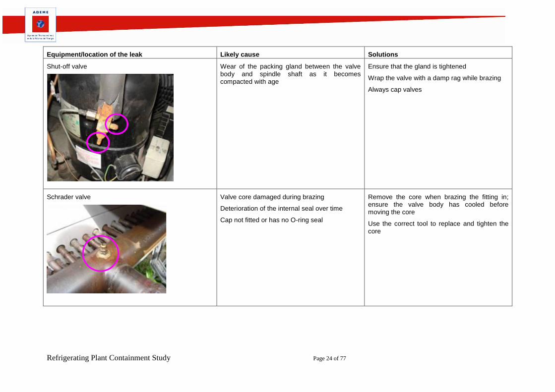
Equipment/location of the leak Likely cause Solutions
Shut-off valve
Wear of the packing gland between the valve body and spindle shaft as it becomes compacted with age
Ensure that the gland is tightened
Wrap the valve with a damp rag while brazing
Always cap valves
Schrader valve
Valve core damaged during brazing
Deterioration of the internal seal over time
Cap not fitted or has no O-ring seal
Remove the core when brazing the fitting in; ensure the valve body has cooled before moving the core
Use the correct tool to replace and tighten the core
Refrigerating Plant Containment Study Page 25 of 77
Flare connection
Loosening of the flare nut due to high thermal expansion due to wide temperature variation (especially for those at the outlet of expansion valves)
Poor flare preparation (causing leakage from initial installation)
Over-tightening, leading to damage at the copper flare face and the flare nut
Under-tightening of the flare connection
Where possible, avoid using flare connections. If they cannot be avoided:
Use flare solders adaptors. Ensure the copper seal is located correctly
Carefully prepare the flare, cutting and de-burring the pipe using appropriate tools,
Check the flare size so it does not foul the flare nut on the pipe
Lubricate the flare and nut with a small amount of refrigeration grade oil
Use a torque wrench to tighten to the setting provided by the equipment manufacturer
Mechanical joints and flanges
Incorrectly prepared joint, gasket not replaced
Uneven tightening of flanges
Incorrect torque used for tightening bolts
Do not use PTFE on HFC refrigerants. Use an appropriate thread sealant.
When replacing gaskets on flanges, remove all the old gasket material from the surface before applying the new one
Tighten flanges down applying the ‘opposites’ rule until the flange is seated correctly
Use a torque wrench
Refrigerating Plant Containment Study Page 26 of 77
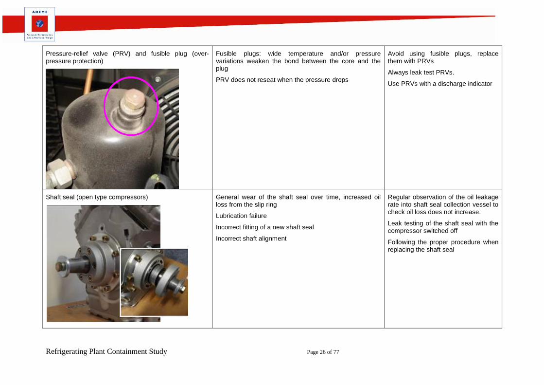
Pressure-relief valve (PRV) and fusible plug (over-pressure protection)
Fusible plugs: wide temperature and/or pressure variations weaken the bond between the core and the plug
PRV does not reseat when the pressure drops
Avoid using fusible plugs, replace them with PRVs
Always leak test PRVs.
Use PRVs with a discharge indicator
Shaft seal (open type compressors)
General wear of the shaft seal over time, increased oil loss from the slip ring
Lubrication failure
Incorrect fitting of a new shaft seal
Incorrect shaft alignment
Regular observation of the oil leakage rate into shaft seal collection vessel to check oil loss does not increase.
Leak testing of the shaft seal with the compressor switched off
Following the proper procedure when replacing the shaft seal
Refrigerating Plant Containment Study Page 27 of 77
Condenser
Shell and tube condenser:
Corrosion of the copper and mild steel if the water circulating in the tubes is not treated
Air-cooled condenser:
Corrosion due to aggressive air. Impact damage due to foreign bodies on the fin block. Vibration causing premature failure of the tube bundle
Regular observation of corrosion points.
Periodically check coolant: (chemical dosing)
Position air condensers on a level base
Check that fans are balanced to limit vibration
Line tap valve
Poor fitting of the line tap onto the pipe, or being fitted to badly formed or flattened pipe work.
Use of the wrong size line tap
Loosening of the line tap valve due to vibration
Leak test line taps and replace if possible
Refrigerating Plant Containment Study Page 28 of 77
Pressure switch
Vibration causing the pressure coupler to split or damage to the pressure switch
Pressure coupler chafing
Rupture of the switch bellows due to vibration or hydraulic action
Failure of the flare connection
Poorly supported or fixed pressure switch
Use flexible pressure couplers where possible (stainless steel braided type offer a high degree of strength and mechanical protection.
Make sure pressure couplers do not rub or chafe on other pipes or vibrating surfaces.
Ensure the switch is correctly supported / fixed
Connect the switches to minimise the transfer of vibration into the switch
O-ring
Hardening or flattening, especially when subjected to extremes in temperature
Leakage after retrofitting because of a different reaction to the new oil
Check (for roundness and flexibility) and change the seal if possible
Oil seals before fitting them
Ensure the seal is suitable for the system oil and refrigerant
Refrigerating Plant Containment Study Page 29 of 77
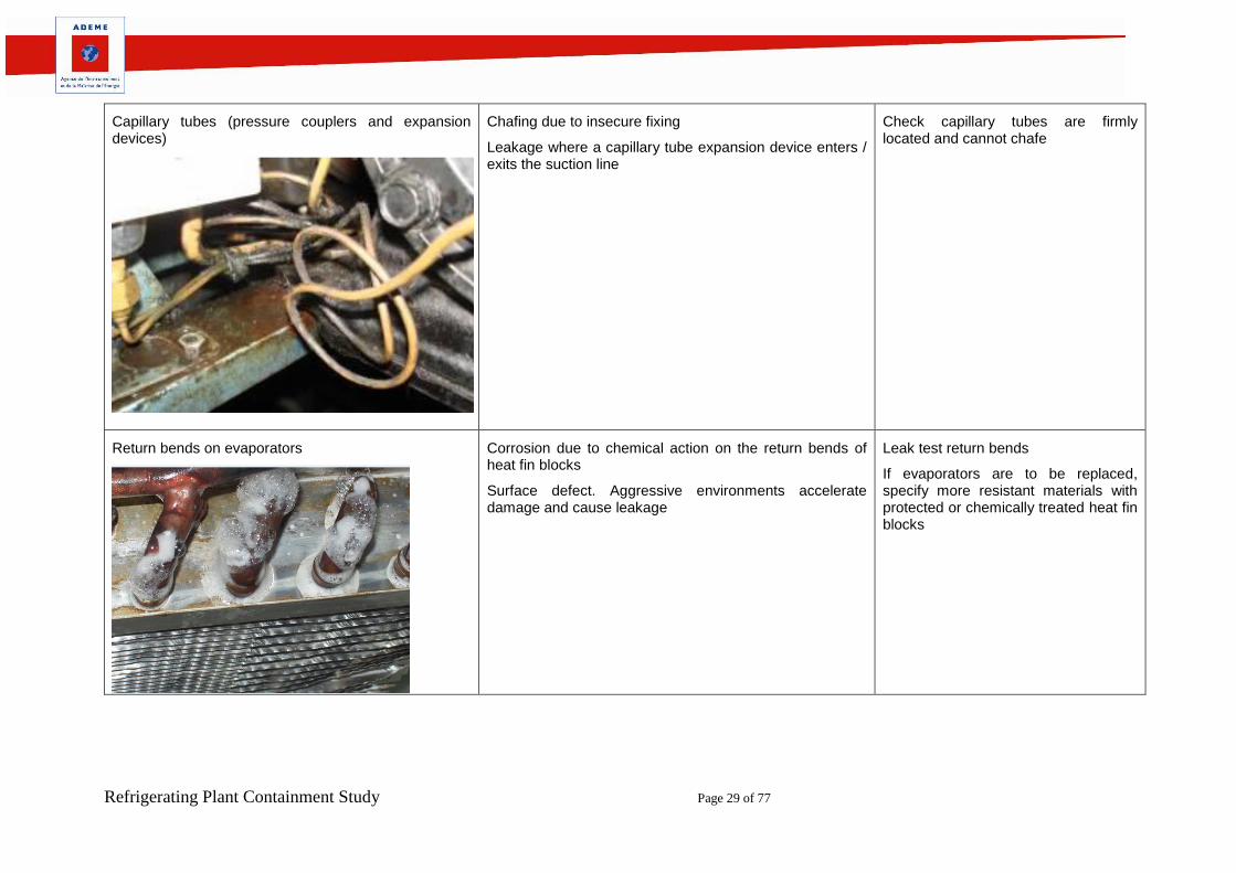
Capillary tubes (pressure couplers and expansion devices)
Chafing due to insecure fixing
Leakage where a capillary tube expansion device enters / exits the suction line
Check capillary tubes are firmly located and cannot chafe
Return bends on evaporators
Corrosion due to chemical action on the return bends of heat fin blocks
Surface defect. Aggressive environments accelerate damage and cause leakage
Leak test return bends
If evaporators are to be replaced, specify more resistant materials with protected or chemically treated heat fin blocks
Refrigerating Plant Containment Study Page 30 of 77
4. Metrological Analysis of Detection Thresholds
4.1. Metrological analysis of needle and digital pressure gauges One of the main tools of the refrigeration technician is the pressure gauge. A pressure gauge is used to
perform a functional test, with the help of a thermometer.
By means of those two instruments, the refrigeration technician is able to check that a refrigerating plant is
functioning properly. However, these measuring instruments, especially the pressure gauge, are not very
accurate and may lead to incorrect interpretation.
To illustrate the interpretation of measurements, IRSTEA laboratory tests were conducted to determine the
influence of the measurement accuracy of needle and digital pressure gauges and its consequences on the
assessment of leakage in a facility.
4.1.1. Testing Conditions Testing was conducted in the IRSTEA laboratory. The purpose was to check the detection threshold of a
needle type pressure gauge and a digital pressure gauge. These pressure gauges were connected to
laboratory equipment capable of increasing or decreasing the pressure as desired, and reading the values
on a digital screen (Druck PC6–IDOS standard).
FIGURE 7. PICTURE OF THE TESTING DEVICE
Refrigerating Plant Containment Study Page 31 of 77
4.1.2. Equipment Three pieces of equipment were used: one digital pressure gauge, one needle type pressure gauge, and
one pressure standard, whose characteristics are shown in Table 7.
TABLE 8. CHARACTERISTICS OF PRESSURE GAUGES USED IN THE TEST
Digital Needle Standard reference
Operating range
0 à 55,15 bar / 0 à 800 psi / -1 à 30 bar -1 à 35 relative bar
0 à 56,25 kg/cm2 / 0 à 5,515 MPa
Accuracy (confidence
interval)
±1% of full range from 0 to 34.47 bar Class 1= ±1% of full range Class 1= ±0.025 of full range
(0-500 psi) range i.e. : ±300 mbar i.e. : ±8,75 mbar
±2,5 % full pressure de 34,47 bar à 55,15 bar (500-800 psi) range
Resolution (possible deviation
between two readings)
0,05 bar / 0,5 psi / 0,05 kg/cm2 / 1 bar 1 mbar
0,005 MPa / 0,1 inHg / 0,5 mmHg
Temperature : 1 °C / 1 °F
from -60°C to -40°C : 10K
from -40°C à +20°C : 5K A
Above 20°C : 1K
Temperature: 1 K
Price 300 Euros 200 Euros 4,000 Euros
4.1.3. Measurement Result A pressure of 10.199 bar was applied. Pressure was dropped to 74 mbar, this pressure drop corresponding
to the detection threshold of the digital pressure gauge.
In the picture below, a 74 mbar pressure drop translates into a 50 mbar pressure drop on the digital
pressure gauge. This is due to the pressure gauge resolution, which is 0.05 bar.
FIGURE 8. RESULT WITH A DIGITAL PRESSURE GAUGE
Refrigerating Plant Containment Study Page 32 of 77
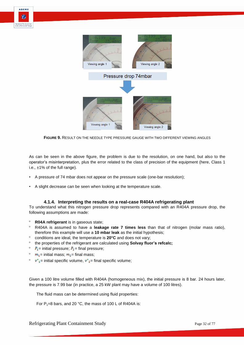
FIGURE 9. RESULT ON THE NEEDLE TYPE PRESSURE GAUGE WITH TWO DIFFERENT VIEWING ANGLES
As can be seen in the above figure, the problem is due to the resolution, on one hand, but also to the
operator’s misinterpretation, plus the error related to the class of precision of the equipment (here, Class 1
i.e., ±1% of the full range).
• A pressure of 74 mbar does not appear on the pressure scale (one-bar resolution);
• A slight decrease can be seen when looking at the temperature scale.
4.1.4. Interpreting the results on a real-case R404A refrigerating plant To understand what this nitrogen pressure drop represents compared with an R404A pressure drop, the
following assumptions are made:
R04A refrigerant is in gaseous state;
R404A is assumed to have a leakage rate 7 times less than that of nitrogen (molar mass ratio),
therefore this example will use a 10 mbar leak as the initial hypothesis;
conditions are ideal, the temperature is 20°C and does not vary;
the properties of the refrigerant are calculated using Solvay fluor’s refcalc;
= initial pressure; = final pressure;
= initial mass; = final mass;
= initial specific volume, = final specific volume;
Given a 100 litre volume filled with R404A (homogeneous mix), the initial pressure is 8 bar. 24 hours later,
the pressure is 7.99 bar (in practice, a 25 kW plant may have a volume of 100 litres).
The fluid mass can be determined using fluid properties:
For P1=8 bars, and 20 °C, the mass of 100 L of R404A is:
Refrigerating Plant Containment Study Page 33 of 77
For P2=7.99 bars, and 20 °C, the mass of 100 L of R404A is:
The loss in mass, therefore, is
That is, 2 kg of refrigerant over 1 year.
Facts to remember
As part of the study, laboratory tests were conducted to determine the influence of the measurement accuracy of needle and digital pressure gauges and its consequences on the assessment of leakage in a facility.
These tests have shown that despite ideal conditions, needle type pressure gauges can only detect leaks equivalent to 2 kg/yr. on a plant which may contain up to 20 kg of R404A refrigerant.
This detection method therefore cannot be used as a substitute for leak testing by direct methods, to be performed on the entire plant, both when a plant is commissioned and during routine inspection.
4.2. Influence of leak detector operating conditions During the study, Cemafroid metrologists sought to examine how the method of use of the leak detectors
influenced the performance of the measuring instruments.
4.2.1. Testing Conditions The study was conducted within the Cemafroid Metrological Laboratory
Lab data:
Temperature: 21.3 °C (+/- 0.1);
Humidity: 29.1% (+/- 0.1);
No draught.
4.2.2. Equipment 1 calibrated leak belonging to TECNEA Italy.
o Type: FET-115
o Gas: R-134a
o Serial number: 016769
2 leak detectors belonging to Cemafroid – D-TEK Select.
o EQT-FRE-169
o LG 11-030
Refrigerating Plant Containment Study Page 34 of 77
One meter
Note: the calibrated leak used was calibrated at 5 g/yr. only. Results are based on the user documentation
and are given for information only.
4.2.3. Diagram of the Device
FIGURE 10. DIAGRAM OF THE TESTING DEVICE
4.2.4. Protocol Determine the detector reaction time:
- Start the leak detector and wait until configuration is complete;
- Set a determined flow of gas using the calibrated leak;
- Position the detector facing the leak (less than 1 cm away);
- Measure the response time.
Determine how the detector/leak distance influences gas detection:
- Start the leak detector and wait until configuration is complete;
- Set a determined flow of gas using the calibrated leak;
- Place the leak detector 10 cm away from the calibrated leak and bring it closer until gas is detected;
- At this stage, note the distance from the leak detector to the calibrated leak.
4.2.5. Measurement Results TABLE 8. DETERMINATION OF DETECTOR RESPONSE TIME
Leakage rate
(g/yr.)
Response time
EQT-FRE-169 LG 11-030
4,5 Immediate Immediate
7,9 Immediate Immediate
13,7 Immediate Immediate
TABLE 9. DETERMINATION OF HOW THE DETECTOR/CALIBRATED LEAK DISTANCE INFLUENCES GAS DETECTION
Refrigerating Plant Containment Study Page 35 of 77
Leakage rate
(g/yr.)
Minimum detection distance (mm)
EQT-FRE-169 LG 11-030
2,6 0 0
4,5 2 0
5,8 4 4
7,9 9 7
10,3 12 13
13,7 13 13
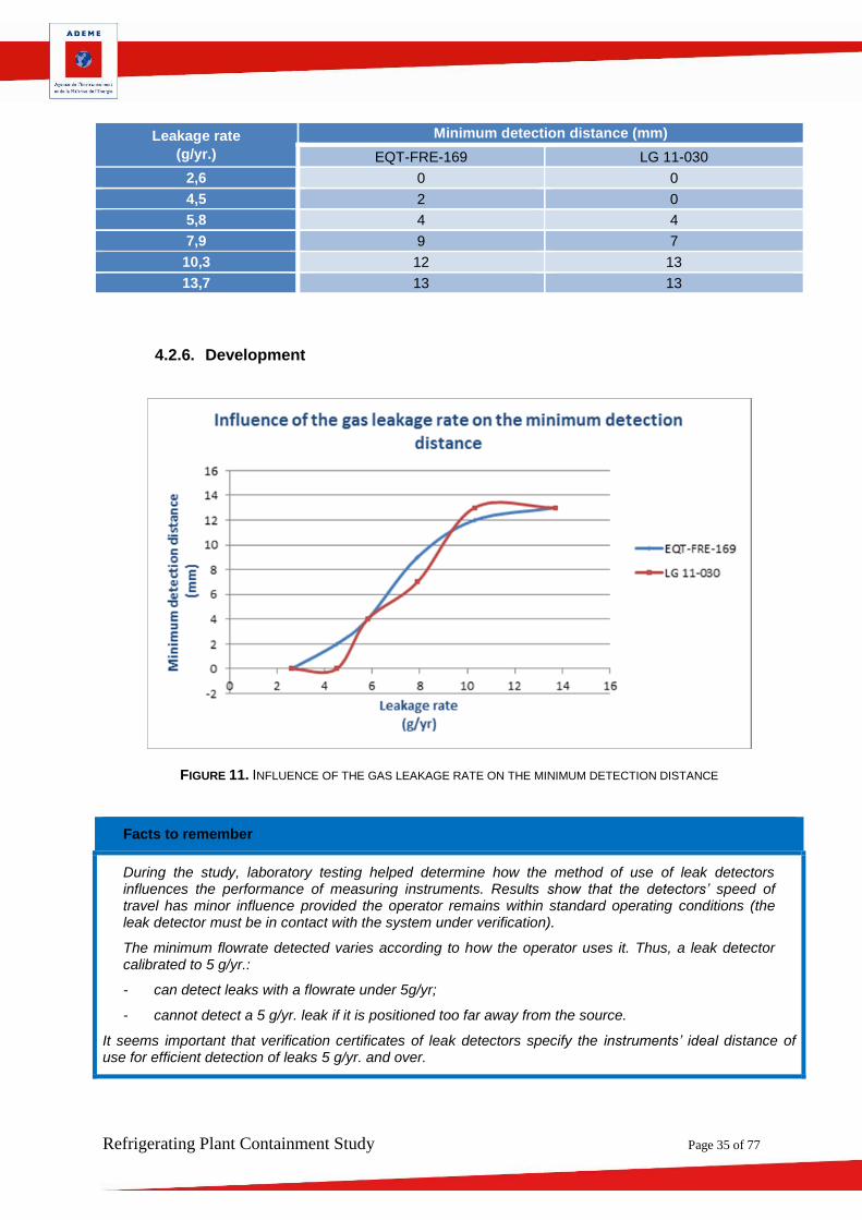
4.2.6. Development
FIGURE 11. INFLUENCE OF THE GAS LEAKAGE RATE ON THE MINIMUM DETECTION DISTANCE
Facts to remember
During the study, laboratory testing helped determine how the method of use of leak detectors influences the performance of measuring instruments. Results show that the detectors’ speed of travel has minor influence provided the operator remains within standard operating conditions (the leak detector must be in contact with the system under verification).
The minimum flowrate detected varies according to how the operator uses it. Thus, a leak detector calibrated to 5 g/yr.:
- can detect leaks with a flowrate under 5g/yr;
- cannot detect a 5 g/yr. leak if it is positioned too far away from the source.
It seems important that verification certificates of leak detectors specify the instruments’ ideal distance of use for efficient detection of leaks 5 g/yr. and over.
Refrigerating Plant Containment Study Page 36 of 77
4.3. Analysis of Recommended Detection Thresholds
4.3.1. Appraisal of Current Detection Methods The vast majority of leak tests are performed with electronic leak detectors having a detection threshold in
the range of 5 g/yr. This threshold is defined in the Order of 7 May 2007 regarding the leak testing of
components ensuring the containment of refrigerants used in refrigerating and air-conditioning equipment.
One article [27] drew our attention to the importance of the sensitivity threshold of leak measuring
apparatuses.
This document presents quantitative leak measurement methods, both in laboratories and on industrial
sites. Various components were subjected to laboratory analysis, and 3,600 measuring points distributed
across 15 sites were checked.
Onsite measurements were carried out with equipment capable of estimating the leakage level (multigas
mass spectrometer with sniffer). The plants audited are those having components (flanges, valves,
couplers, etc.) which may generate leakage. The selected sites are high capacity facilities using fluorinated
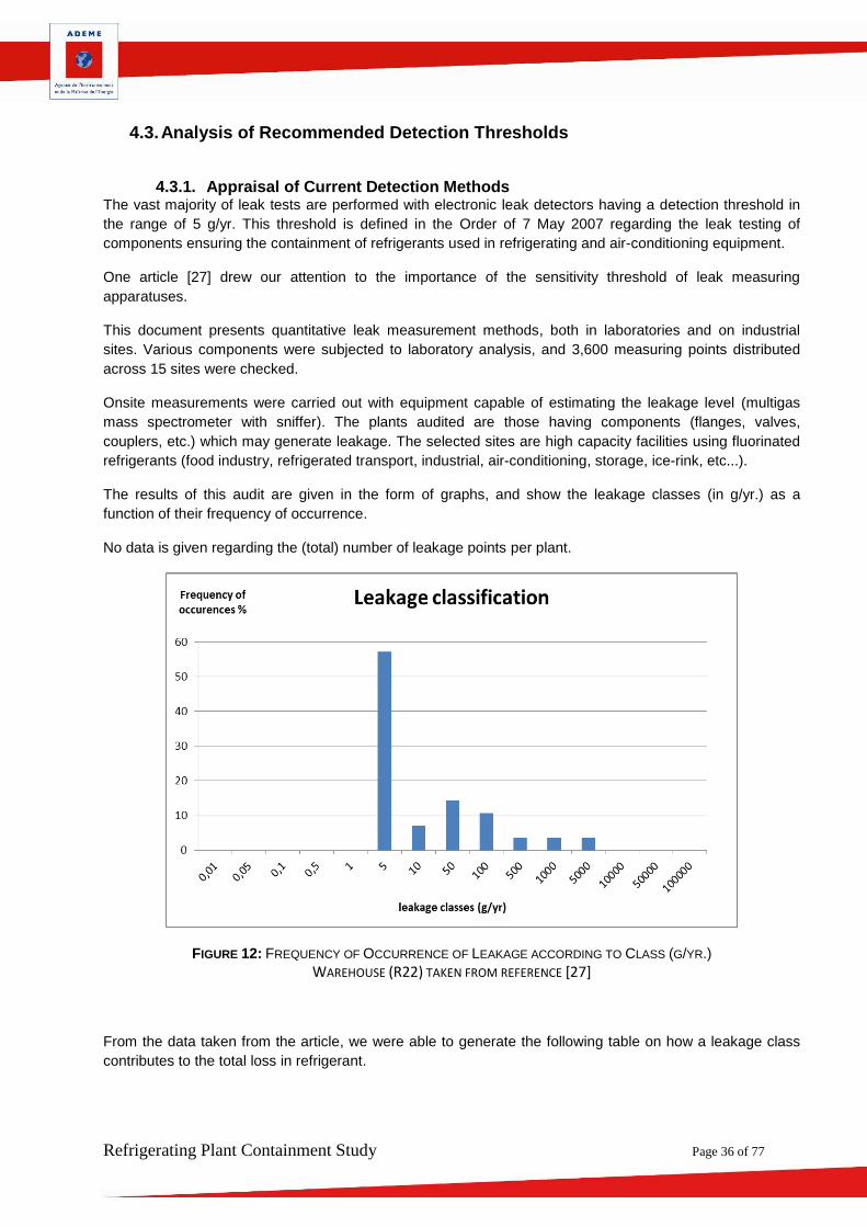
The results of this audit are given in the form of graphs, and show the leakage classes (in g/yr.) as a
function of their frequency of occurrence.
No data is given regarding the (total) number of leakage points per plant.
FIGURE 12: FREQUENCY OF OCCURRENCE OF LEAKAGE ACCORDING TO CLASS (G/YR.)
WAREHOUSE (R22) TAKEN FROM REFERENCE [27]
From the data taken from the article, we were able to generate the following table on how a leakage class
contributes to the total loss in refrigerant.
Refrigerating Plant Containment Study Page 37 of 77
Frequency of
occurrence (Fr in
%)
Leakage Class (Cl
in g/yr)
Class Contribution to
total loss (Cc in %/ yr)
Potential loss of
mass mp (kg/yr)
forr N = 100
0% 0,5 0,0000% 0,00
0% 1 0,0000% 0,00
57% 5 1,12% 0,29
7% 10 0,28% 0,07
14% 50 2,80% 0,72
11% 100 4,19% 1,07
4% 500 7,05% 1,8
4% 1000 14,09% 3,6
4% 5000 70,47% 18
0% 10000 0,00% 0,00
0% 50000 0,00% 0,00
Total mass mtot 26 kg/yr
TABLE 10: CALCULATION OF THE CONTRIBUTION OF A CLASS TO TOTAL LOSS, AND CALCULATION OF THE MASS
POTENTIALLY LOST PER YEAR FOR A NUMBER OF LEAKS EQUAL TO 100
From this table it can be seen that leaks with the highest frequency of occurrence (57% of 5 g/yr. class
leaks) represent only a very low relative contribution of 1.12% to the total mass of leakage (refrigerant
potentially lost). This raises the question of whether a 5 g/yr. detection threshold is relevant for leak testing.
Conversely, one can see that 91.6% of the leakage mass is due to classes over 500 g/yr.
From the operator’s point of view, when performing leakage detection, chances are high that the operator
will detect a large number of leaks having negligible impact. In the end, it is also possible that the operator
will stop the analysis even before he has detected significant leakage, particularly on plants that are not
easily accessible. It is important, therefore, to check for leaks thoroughly using several detection means. To
qualify major leaks over 50g/yr., the soap bubble may prove to be the preferred method.
4.3.2. CO2 statement for repair of a 5 g/yr. leak In addition to this first approach analysis, it is of interest to incorporate the environmental impact (e.g., in
terms of carbon footprint) of repairing a 5 g/yr. leak.
Let us take the case of servicing a valve which emits 5g/yr. of refrigerant, placed on a 100-litre liquid tank of
a 70 kW refrigerating plant with T0= -30°C; TK = 35°C.
No consideration is given to:
what is left in the hose;
possible manipulation errors;
refrigerant present in the oil (possibly 10% or more of the oil mass).
If we consider a leak with a rate of Tx=5 g/yr. for N=15 years for a plant containing R404A (GWP: 3900), this
amounts to: N x Tx x GWP= 292 kgeq CO2
Let us now take the case where this 5 g/yr. leak will be repaired. The first objective will be to recover the
plant refrigerant prior to repairing the component causing the leak.
If we consider that in this operation, the recovery unit stops when relative pressure is 0.2 bar, the volume of
the facility being V=100 litres at a temperature of 20°C, density V’’= 0.31 m3/Kg.
Refrigerating Plant Containment Study Page 38 of 77
The resulting residual mass of refrigerant in the plant m=V/V’’=326g.
This residual mass will inevitably be released to the atmosphere during the repair and its impact will
therefore be 1262 kgeq CO2.
This calculation shows that repairing a single 5 g/yr. leak may be much more harmful to the environment
than leaving it as is for 15 years.
This budget demonstrates the value of shut-off valves which can avoid draining the entire plant to perform
the repair, by shutting off only the portion of the system which is to be repaired.
When there is no shut-off valve, one should avoid frequently draining the plant to repair low rate leakages,
or wait until the next preventive maintenance operation to perform the repair.
Facts to remember
The authors of this report wish to draw the reader’s attention to the technical relevance of the current detection threshold level. To be effective when testing for leakage, it would be best to focus mainly on major leaks. Detectors having numerous detection thresholds could be a significant step forward in this area.
Leakage detection has to be carried out exhaustively on the entire installation.
Refrigerating Plant Containment Study Page 39 of 77
5. Result on the Online Survey
5.1. Introduction The online survey was sent to more than 500 French installers/maintainers of refrigerating equipment
holding a qualification certificate. Roughly forty completed questionnaires were returned to us, which
amounts to an 8% response rate. This rate is consistent with the results of a similar study conducted in the
UK (see Datasheet 7). This relatively low participation rate can be explained by the fact that the containment
of facilities remains a sensitive issue for both the refrigeration specialists and the facility owners, although
the authors of the study established strict confidentiality agreements regarding the data supplied. In
addition, the professionals who were contacted mentioned a lack of resources to complete the survey.
The results of the survey in terms of leakage rates are in line with the relevant literature. Drafting
conclusions on non-accident related leakage rates was difficult because the refrigerant refills, as recorded
on the job sheets, essentially relate to serious failures having caused very severe leakage.
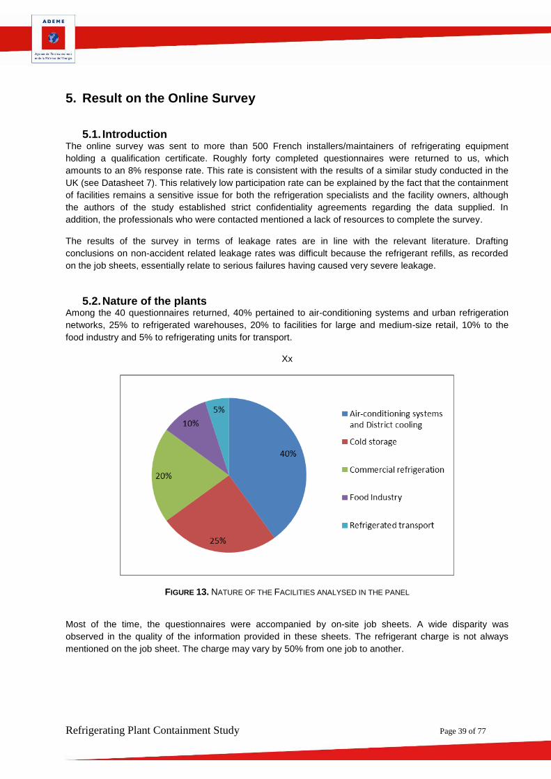
5.2. Nature of the plants Among the 40 questionnaires returned, 40% pertained to air-conditioning systems and urban refrigeration
networks, 25% to refrigerated warehouses, 20% to facilities for large and medium-size retail, 10% to the
food industry and 5% to refrigerating units for transport.
Xx
FIGURE 13. NATURE OF THE FACILITIES ANALYSED IN THE PANEL
Most of the time, the questionnaires were accompanied by on-site job sheets. A wide disparity was
observed in the quality of the information provided in these sheets. The refrigerant charge is not always
mentioned on the job sheet. The charge may vary by 50% from one job to another.
Refrigerating Plant Containment Study Page 40 of 77
5.3. Data Collection
5.3.1. Air-conditioning Pressure tapping connections are frequently incriminated, as are compressor shaft seal fittings.
5.3.2. Refrigerated warehouses Pressure tapping connections are regularly mentioned in the survey responses.
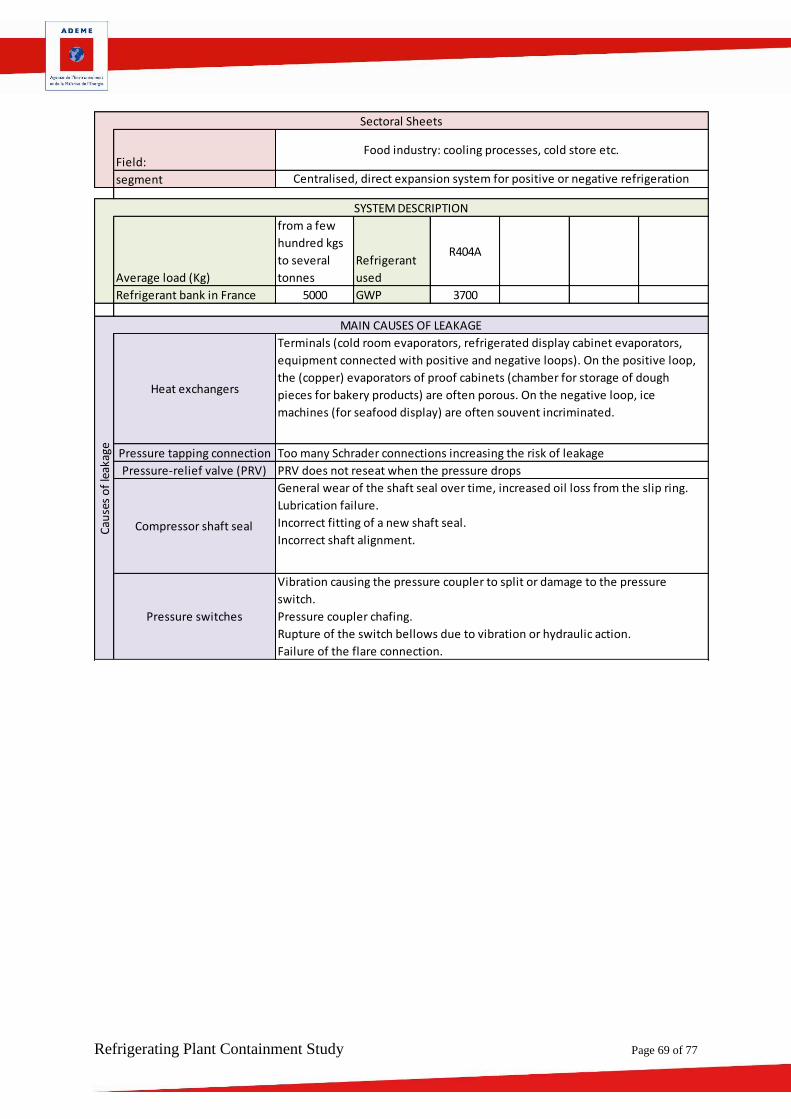
5.3.3. Commercial refrigeration In commercial refrigeration, the main causes of leakage relate to terminals (cold room evaporators,
evaporators for refrigerated display cabinets, equipment connected with positive and negative loops). On
the positive loop, the evaporators (copper-made) of the proofing cabinets (chamber for storage of dough
pieces for bakery products) are often porous. On the negative loop, ice machines (for seafood display) are
often incriminated.
5.3.4. Agrifood Industry In the handful of questionnaires on agrifood industries, major leaks relate to pressure tapping connections,
to liquid line, evaporators of ventilated cold rooms, and discharge slotted tube.
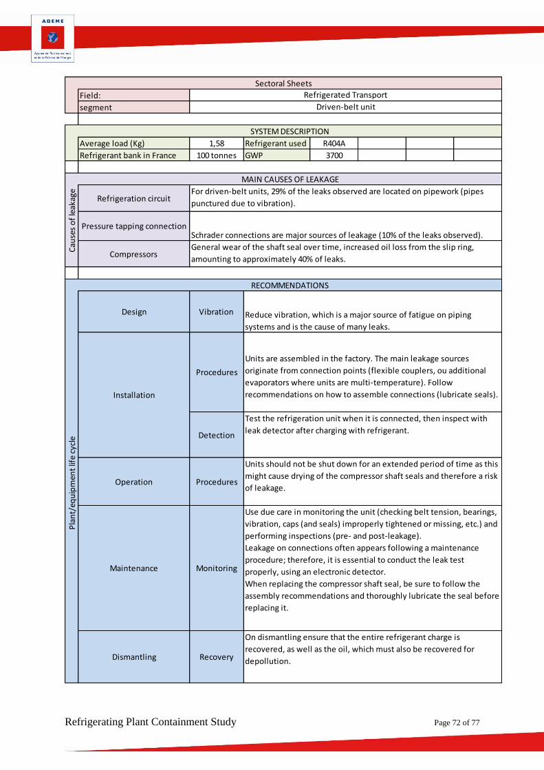
5.3.5. Refrigerated Transport For refrigerated transport, the occurrences and the sources of leakage strongly depend on the technology
used. Driven-belt units are much more susceptible to leakage than independent units. The reason is that
mechanical loads are much heavier.
FIGURE 14. LOCATING LEAKAGE IN TRANSPORT REFRIGERATION UNITS
Refrigerating Plant Containment Study Page 41 of 77
For driven-belt units, 70% of the leaks observed are located on the pipework, at the compressor, at
pressure taps or on seals. To a lesser extent, leaks are found at the valves, the condenser, the expansion
valve or the liquid receiver.
For independent units, whether single- or multi-temperature, 50% of the leaks are located at seal fitting
(compressors or service valves), seals and anacondas. Welds and solders are incriminated only in 5% of
the cases.
Facts to remember
For the study, an online survey was sent to more than 500 French installers/maintainers of refrigerating equipment holding a qualification certificate. The response rate was 8% which is a satisfactory result in view of the response rates of earlier studies. Generally, the causes of leakage found are the same as those found in the literature, with marked differences according to the line of activity and the technology used.
The quality of job sheets and leak test reports is very irregular. It would seem relevant to develop a leakage detection procedure or method which uses several types of detection systems and a number of compulsory check points.
In addition, given the wide range of applications and refrigeration systems, the detection method should vary according to the types of facilities.
Refrigerating Plant Containment Study Page 42 of 77
6. On-site Assessment of equipment or facility
6.1. Introduction Visits were conducted by Cemafroid experts, the facilities being visited on the basis of the previously
completed questionnaires. About twenty visits were conducted in all areas of refrigeration:
- Air-conditioning systems;
- Refrigerated warehouses;
- Refrigerating plants in large and medium-size retail stores;
- District Cooling;
- Food industry.
During these visits the technical documentation of the facility was examined, as well as the job sheets.
Where possible, the experts examined the maintenance contract to check the frequency and the periodic
checkpoints performed.
The experts analysed the facilities by answering the analysis grid provided in Appendix 2. The completed
sheets are given in Appendix 4.
6.1.1. District Cooling / Air conditioning system In general, refrigerating plant which have been visited were well-maintained (Sheets n°1, 4, 6 and 18 in
Appendix 4). For this kind of large facilities, maintenance operations, including leak tests, were performed
internally, with frequency well beyond the regulations requirements. Leak detection methods look like not
well adapted for large refrigerating plant and should be revised. Even if refrigerant recovery operations were
performed correctly, in some cases, still a large amount of refrigerant stays dissolved in oil. Operation
sheets could be completed in more valuable way.
6.1.2. Warehouses Visited facilities (Sheets n ° 3, 9, 10, 11 and 14 of annex 4) were relatively new for most of them with
massive recourse to hoses which accentuate the risk of leak if they are not changed periodically. Despite a
customer high level of satisfaction and a maintenance contract planning many controls and preventive
maintenance, a R404A installation was in advanced dilapidation status (missing cap, advanced corrosion
and presence of mud to the right of the compressors).
6.1.3. Commercial refrigeration, supermarkets and hypermarkets Visited facilities (Sheets n ° 5, 8, 12, 13, 16 and 17 of Schedule 4) are a massive recourse to hoses which
accentuates the risk of leak if they are not changed periodically. In addition, facilities are characterized
almost systematically by a massive number of Schrader valve and missing plugs.
6.1.4. Agrofood industry The visited facilities (Sheets n ° 2, 7 and 15 of Schedule 4) are all relatively old with much corroded
components. Installations are generally well maintained.
Refrigerating Plant Containment Study Page 43 of 77
6.2. Feedback In general, there are major differences of approach in maintenance contracts. Most of the refrigerated
warehouses and urban refrigerating plants visited maintained their facilities particularly well, but
maintenance contracts for air-conditioning systems, large and medium-size retail facilities on the other
hand, included little or no preventive maintenance or replacement of worn parts.
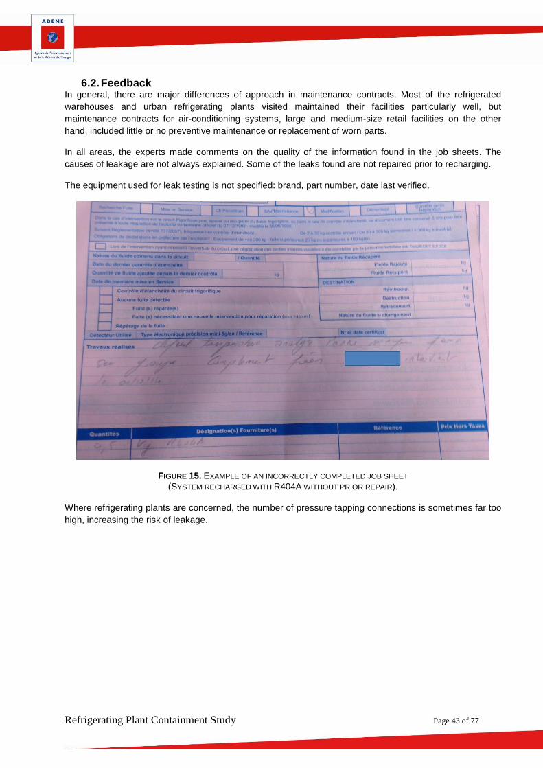
In all areas, the experts made comments on the quality of the information found in the job sheets. The
causes of leakage are not always explained. Some of the leaks found are not repaired prior to recharging.
The equipment used for leak testing is not specified: brand, part number, date last verified.
FIGURE 15. EXAMPLE OF AN INCORRECTLY COMPLETED JOB SHEET
(SYSTEM RECHARGED WITH R404A WITHOUT PRIOR REPAIR).
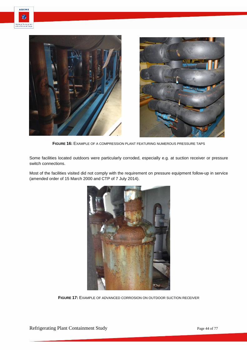
Where refrigerating plants are concerned, the number of pressure tapping connections is sometimes far too
high, increasing the risk of leakage.
Refrigerating Plant Containment Study Page 44 of 77
FIGURE 16: EXAMPLE OF A COMPRESSION PLANT FEATURING NUMEROUS PRESSURE TAPS
Some facilities located outdoors were particularly corroded, especially e.g. at suction receiver or pressure
switch connections.
Most of the facilities visited did not comply with the requirement on pressure equipment follow-up in service
(amended order of 15 March 2000 and CTP of 7 July 2014).
FIGURE 17: EXAMPLE OF ADVANCED CORROSION ON OUTDOOR SUCTION RECEIVER
Refrigerating Plant Containment Study Page 45 of 77
FIGURE 18. EXAMPLE OF A HIGHLY CORRODED COMPRESSOR FLANGE
FIGURE 19. PRESENCE OF OIL ON THE GROUND
Refrigerating Plant Containment Study Page 46 of 77
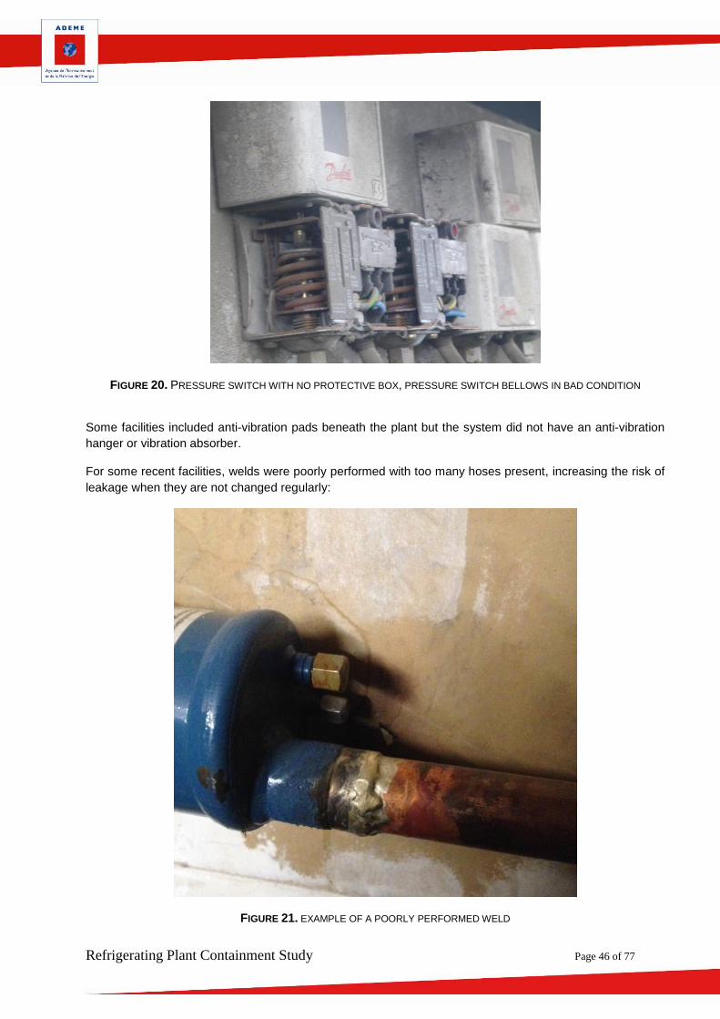
FIGURE 20. PRESSURE SWITCH WITH NO PROTECTIVE BOX, PRESSURE SWITCH BELLOWS IN BAD CONDITION
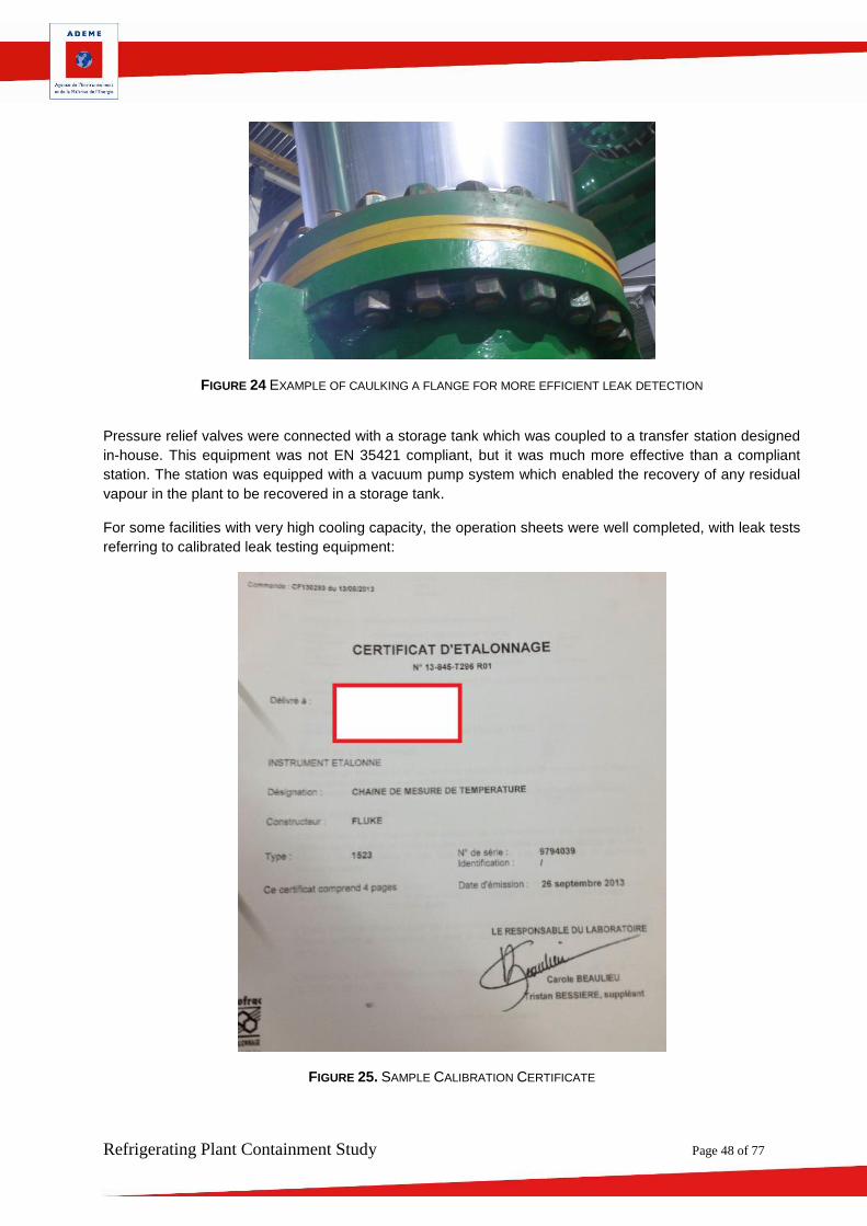
Some facilities included anti-vibration pads beneath the plant but the system did not have an anti-vibration
hanger or vibration absorber.
For some recent facilities, welds were poorly performed with too many hoses present, increasing the risk of
leakage when they are not changed regularly:
FIGURE 21. EXAMPLE OF A POORLY PERFORMED WELD
Refrigerating Plant Containment Study Page 47 of 77
FIGURE 22. SYSTEMATIC PRESENCE OF HOSES
FIGURE 23. NO PLUG ON VALVE
The experts also observed some excellent practices in major District cooling refrigerating plants, including
the caulking of leakage-susceptible components to better detect possible leaks.
Refrigerating Plant Containment Study Page 48 of 77
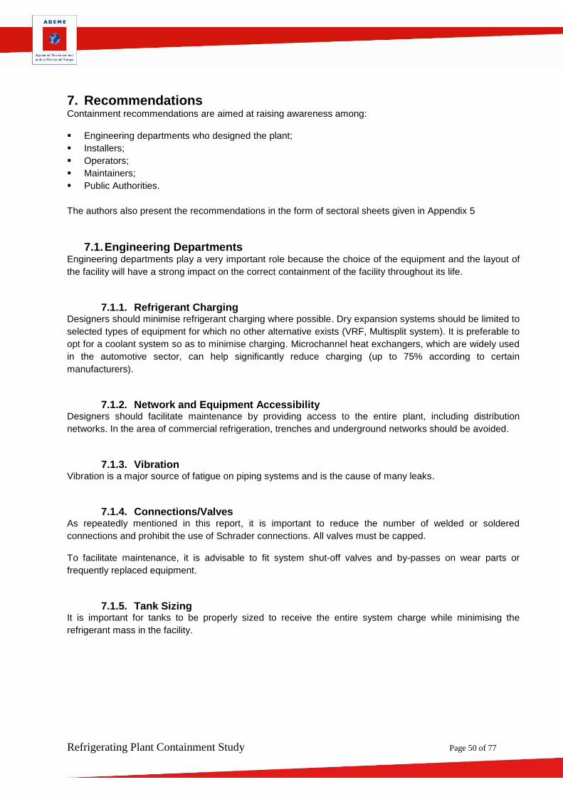
FIGURE 24 EXAMPLE OF CAULKING A FLANGE FOR MORE EFFICIENT LEAK DETECTION
Pressure relief valves were connected with a storage tank which was coupled to a transfer station designed
in-house. This equipment was not EN 35421 compliant, but it was much more effective than a compliant
station. The station was equipped with a vacuum pump system which enabled the recovery of any residual
vapour in the plant to be recovered in a storage tank.
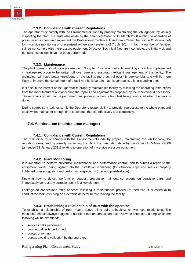
For some facilities with very high cooling capacity, the operation sheets were well completed, with leak tests
referring to calibrated leak testing equipment:
FIGURE 25. SAMPLE CALIBRATION CERTIFICATE
Refrigerating Plant Containment Study Page 49 of 77
Facts to remember
During the study, about twenty site visits were completed on facilities in all areas of refrigeration. There are wide disparities in terms of maintenance according to the area under consideration. Regardless of the area, experts commented on the quality of the information found in the job sheets. The causes of leakage are not always explained. Some of the leaks noted are not repaired prior to recharging, which is strictly forbidden.
The majority of the facilities visited were not compliant with the Pressure Equipment Directive regarding the in-service equipments follow up, and showed advanced corrosion. The compliant facilities, which were periodically inspected, were much better maintained.
Refrigerating Plant Containment Study Page 50 of 77
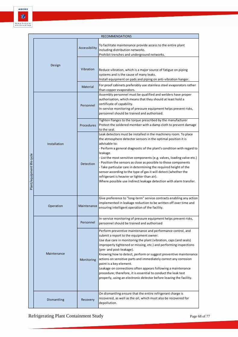
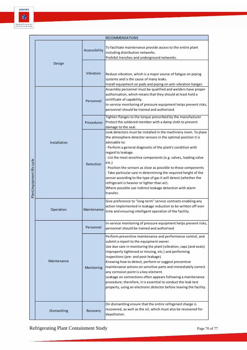
7. Recommendations Containment recommendations are aimed at raising awareness among:
Engineering departments who designed the plant;
Installers;
Operators;
Maintainers;
Public Authorities.
The authors also present the recommendations in the form of sectoral sheets given in Appendix 5
7.1. Engineering Departments Engineering departments play a very important role because the choice of the equipment and the layout of
the facility will have a strong impact on the correct containment of the facility throughout its life.
7.1.1. Refrigerant Charging Designers should minimise refrigerant charging where possible. Dry expansion systems should be limited to
selected types of equipment for which no other alternative exists (VRF, Multisplit system). It is preferable to
opt for a coolant system so as to minimise charging. Microchannel heat exchangers, which are widely used
in the automotive sector, can help significantly reduce charging (up to 75% according to certain
manufacturers).
7.1.2. Network and Equipment Accessibility Designers should facilitate maintenance by providing access to the entire plant, including distribution
networks. In the area of commercial refrigeration, trenches and underground networks should be avoided.
7.1.3. Vibration Vibration is a major source of fatigue on piping systems and is the cause of many leaks.
7.1.4. Connections/Valves As repeatedly mentioned in this report, it is important to reduce the number of welded or soldered
connections and prohibit the use of Schrader connections. All valves must be capped.
To facilitate maintenance, it is advisable to fit system shut-off valves and by-passes on wear parts or
frequently replaced equipment.
7.1.5. Tank Sizing It is important for tanks to be properly sized to receive the entire system charge while minimising the
refrigerant mass in the facility.
Refrigerating Plant Containment Study Page 51 of 77
7.2. Installation
7.2.1. Personnel Assembly personnel must be qualified and welders have proper authorisation, which means that they
should at least hold a certificate of capability.
Vocational training is a key issue for the refrigeration technician, since he/she is expected to acquire
additional skills especially on natural refrigerant or risk-bearing technologies (equipment of category 1 to 4
according to the PED).
7.2.2. Sensitive Procedures A number of procedures can help avoid leakage and should be taken into account by the installer when
performing the assembly:
Protect the soldered member with a damp cloth to prevent damage to the seal;
Tighten to the torque prescribed by the manufacturer;
For flares, use an eccentric flaring tool;
Tighten flanges to the specified torque applying the cross-pattern rule in 3 gradual passes;
Ensure the pressure switch is properly fixed and supported.
On commissioning, the installer should:
Leak test the entire plant. All connections should be checked using a spray or ultrasonic detector;
Explain the role of maintenance. Thus the operator should adopt a consulting approach with respect to
the owner in regard to his responsibilities.
7.2.3. Detection Equipment Leak detectors must be installed in the machinery room. To place the atmosphere detector sensors in the
best position, it is advisable to:
Perform a general diagnostic of the plant’s condition in terms of leakage;
List the most sensitive components (e.g., valves, unloading valve etc.);
Position the sensors as close as possible to those components;
Take particular care in determining the required height of the sensor according to the type of gas it will
detect (whether the refrigerant is heavier or lighter than air).
Where possible use indirect leakage detection with alarm transfer.
7.3. Operation (equipment owner) The comments hereafter are intended for owners of refrigerating equipment. Keep in mind that F-Gas
establishes the owner as responsible for the proper containment of his refrigerating plant. Operators are
required to properly maintain their facilities. In general, few operators are familiar with their refrigerating
plant and too often rely on their maintenance providers. It seems important that the operator, in the same
way as he monitors his energy use, be capable of monitoring his leakage rate.
7.3.1. Plant Design The operator should accept the adjustments and the design layout proposed by the engineering
department, aiming to minimise leakage and facilitate detection and repair (see Engineering Department
Paragraph).
Refrigerating Plant Containment Study Page 52 of 77
7.3.2. Compliance with Current Regulations The operator must comply with the Environmental Code by properly maintaining the job logbook, by visually
inspecting the plant. He must also abide by the amended Order of 15 March 2000 relating to operation of
pressure equipment and implement the Professional Technical Handbook (Cahier Technique Professionnel)
for in-service monitoring of pressurized refrigeration systems of 7 July 2014. In fact, a number of facilities
still do not comply with the pressure equipment Directive. Technical files are incomplete, the initial visit and
periodic inspections have not been performed.
7.3.3. Maintenance The plant operator should give preference to “long term” service contracts, enabling any action implemented
in leakage reduction to be written off over time and ensuring intelligent management of the facility. The
maintainer will have better knowledge of the facility, more control over his service jobs and will be more
likely to improve the containment of a facility, if he is certain that his contract is a long-standing one.
It is also in the interest of the Operator to properly maintain his facility by following the operating instructions
from the manufacturers and accepting the repairs and adjustments proposed by the maintainer if necessary.
These repairs should not be performed precipitously, without a leak test being conducted when the work is
done.
During compulsory leak tests, it is the Operator’s responsibility to provide free access to the whole plant and
to allow the maintainer enough time to conduct the test effectively and completely.
7.4. Maintenance (maintenance manager)
7.4.1. Compliance with Current Regulations The maintainer must comply with the Environmental Code by properly maintaining the job logbook, the
reporting forms, and by visually inspecting the plant. He must also abide by the Order of 15 March 2000
(amended 31 January 2011) relating to operation of in-service pressure equipment.
7.4.2. Plant Monitoring It is important to perform preventive maintenance and performance control, and to submit a report to the
equipment owner, being vigilant into the installation monitoring (for vibration, caps and seals improperly
tightened or missing, etc.) and performing inspections (pre- and post-leakage).
Knowing how to detect, perform or suggest preventive maintenance actions on sensitive parts and
immediately correct any corrosion point is a key element.
Leakage on connections often appears following a maintenance procedure; therefore, it is essential to
conduct the leak test using an electronic detector before leaving the facility.
7.4.3. Establishing a relationship of trust with the operator To establish a relationship of trust means above all to build a healthy, win-win type relationship. The
maintainer should always suggest to his client that an annual contract review be conducted during which the
following will be examined:
services calls performed;
contractual visits performed;
quotes drawn up;
quotes awaiting validation by the operator;
Refrigerating Plant Containment Study Page 53 of 77
refrigerant consumption;
24/24 service jobs;
Operator’s expectations and issues for the coming months;
potential usage problems;
energy consumption;
Regulatory watch.
This contract review is an opportunity to assess the leakage rate of the facility and, together with the client,
to validate solutions to minimise it.
7.4.4. Leak Test To conduct a quality leak test, the maintainer should follow a number of rules:
Allow enough time to conduct the test and have it planned in the contract;
Test the electronic detector with a calibrated leak prior to conducting the test;
Search for leaks methodically as recommended by F-Gas;
Check all connections using a spray or ultrasonic detector;
Always leak test inside the pressure switch, keeping in mind the risk of electric shock;
Leak test return bends carefully, especially if the atmosphere is aggressive;
Always leak test safety pressure valves and fusible plugs;
Test for leakage as soon as an oil trace appears
If leakage is confirmed, repair as soon as possible and recheck the system at the repair point within a
month
Have the facility tested by qualified personnel. Leak testing pressure should be maintained at least 24
hours for commissioning, and 1 hour when replacing a part (a small portion of a system);
Use tracer gas (helium or hydrogen) with the appropriate associated detector (your HCFC/HFC detector
will not work for this type of gas);
Wipe off traces of fluorescent product used to detect leakage;
Keep in mind that the first leak found may not be the last.
7.5. Public Authorities The following comments are intended for ministries, associations, public institutions, European committees.
7.5.1. Relying on the studies carried out There are a number of studies on the issue of containment. In addition to this report, Public Authorities
should make use of the studies carried out by ADEME, AFCE, Armines, Cetim, Cemafroid, IRSTEA,
Perifem, and UNICLIMA.
According to these studies there are significant differences in containment, depending on the technologies
employed and the line of activity.
This study raises the technical relevance of substantially increasing the detection thresholds of the detectors
to make leak testing more effective.
Furthermore, because of the more stringent regulations on fluorinated refrigerants and the implementation
of some degree of traceability in refrigerant flows, refrigerant handling organisations are required to be
aware of the flows for which they are responsible, but this traceability is only relative when it comes to the
operator or the equipment. The authors of this report wish to draw the Public Authorities attention to the
importance of setting up flow traceability at operator or refrigerating plant level.
Refrigerating Plant Containment Study Page 54 of 77
7.5.2. Regulatory and Normative Context PED 2014/68/EU, the Pressure Equipment Directive, introduces requirements on the manufacture of
refrigerating plants or refrigerating equipment which make up assemblies used in refrigeration and air-
conditioning. These requirements on the safety of pressure devices help improve containment.
The EN 378 standard on refrigeration systems and heat pumps, and the EN 13480-5 standard on inspection
and testing of industrial piping are harmonised with the PED and provide selection criteria for the design and
operation of refrigerating plants which help minimise refrigerant leaking through regular testing and
inspection of the system.
Public Authorities can rely on the existing regulatory texts which support proper containment of facilities.
The authors of this report wish to draw the Public Authorities’ attention to the importance of establishing
standard rules for detection methods in order to ensure comprehensiveness of the leak testing process.
Refrigerating Plant Containment Study Page 55 of 77
8. References
1 Clodic D, Yu Y, Final report of AHRTI n°09006, AHRTI, 2014.
2 IoR, Designing out leaks: design standards and practices, Projet Européen: real skills Europe, 2011
4 Robert O, Le confinement d’une grosse installation, Colloque AFCE effet de serre V, 2006
5 IoR, Real zero case study 2, Projet Européen: real skills Europe, 2009
6 Johnson E. P., Air-source heat pump carbon footprints: HFC impacts and comparison to other heat
sources , Energy Policy 39 (2011) 1369–1381, 2011
7 LSBU, Eunomia Research & Consulting Ltd and the Centre for Air Conditioning and Refrigeration
Research, Impacts of Leakage from Refrigerants in Heat Pump, 2014
8 C. Aprea et R. Mastrullo, An experimental evaluation of the vapour compression plant performances
in presence of R407C leaks using an electronic expansion valve, Applied Thermal Engineering Volume 22,
Issue 2, February 2002, Pages 161–171, 2002
9 C. Aprea, F de Rossi et C. Renno, Analysis of some recharge solutions on varying the R407C
composition, Energy Conversion and Management 50 (2009) 2288–2295, 2009
22 Gallagher et al., High-Global Warming Potential Fgas Emissions in California, Environ. Sci. Technol.
2014, 48, 1084−1093, 2014
23 Brochure Emerson, Choix de réfrigérants pour la réfrigération commerciale – Trouver le bon
équilibre, 2009
24 Alfi M, Détecteurs de fuites: principe et offre commerciale, IoR, 1995
25 Clodic D, Measurement and control of refrigerant leaks, 2000
26 I.N Grace, D.Datta, S.A. Tassou, Sensitivity of refrigeration system performance to charge,
Department of Mechanical Engineering, Brunel University, 2004
27 Huchet A, Cazauran X, Hermon C, Morio Y,S, Guyot YS, Containment of refrigerating plants
« rapport final 2004 », ADEME/Groupe de travail Confinement du CETIM-CETIAT/ commission MFCE du
CETIM, Avril 2005.
28 X. Cazauran, J. Pioger, Détection de fuite: méthodes directes et indirectes, AFCE - Colloque Effet
de Serre VIII, 2009
29 Tassou SA, Grace IN,"Fault diagnosis and refrigerant leak detection in vapour compression
refrigeration systems" International Journal of Refrigeration 28 (2005) 680–688, 2005.
30 J. Navarro-Esbrı, E. Torrella, R. Cabello "A vapour compression chiller fault detection technique
based on adaptative algorithms. Application to on-line refrigerant leakage detection", Institute of
refrigeration IJR, 2006
31 Heng Sun, Dan Shu, Zhihua Jiang, "Simulation study of the dynamic performance of a MRC plant
with refrigerant charged or leaked", Cryogenics, 2012.
32 REAL SKILLS EUROPE, Institute of refrigeration; Europe; Real Skills Europe (RSE), 2011
33 Guide illustré de 13 fuites courantes, Institute of refrigeration; Europe; Real Skills Europe (RSE) ,
traduction AFCE.
34 Concevoir sans fuites, Institute of refrigeration; Europe; Real Skills Europe (RSE), traduction AFCE,
2011
35 Guide du bon contrôle de fuite, IoR; Europe; Real Skills Europe (RSE), 2011
36 Importance des fuites: les responsabilités des détenteurs d’équipement, IoR; Real Skills Europe
(RSE), 2011
37 "Refrigerant Management Program Question and Answer Guidance Document", Californie, 2013
38 JLN (professeur), Guide pour l'analyse de l'existant technique
39 Compliance Guidance For Industrial Process Refrigeration Leak Repair Regulations Under Section
608 Of The Clean Air Act, "The Chemical Manufacturers Association, The Environmental Protection
Agency", 1995
40 March Consulting Group, An Independent Review of the Role of HFC Refrigerants, European
Fluorocarbon Technical Committee, a Sector Group of CEFIC, 1997
Refrigerating Plant Containment Study Page 57 of 77
41 D. Colbourne, K.O. Suen, Equipment design and installation features to disperse refrigerant
releases in rooms—part I: experiments and analysis, International Journal of Refrigeration 26 (2003) 667–
673, 2003
42 British refrigeration association, Code of practice for refrigerant leak tightness in compliance with
the F-Gas regulation, Institute of Refrigeration, 2007
43 Leakage matters: the equipment owner's responsibilities, Institute of Refrigeration, 2009
44 I. Morgado, J.C. Legras, D. Clodic, Primary standard for the calibration of refrigerant leak flow rates,
Metrologia magazine, 2010
45 Cowan D., Gartshore J, Chaer I, Francis C, Maidment G., REAL Zero – Reducing refrigerant
emissions & leakage - feedback from the IOR Project, Institute of Refrigeration, 2009
46 Bender F, Skrypnik A, Voigt A, Marcoll J, Rapp M, Selective Detection of HFC and HCFC
Refrigerants using a Surface Acoustic Wave Sensor System, Anal. Chem. 2003, 75, 5262-5266, 2003
47 Importance des fuites: les responsabilités des opérateurs, Institute of Refrigeration; Europe; Real
Skills Europe (RSE), 2011
48 Galloway J, Examination of the Global Warming Potential of Refrigeration in the Food Chain,
Department for Environment Food & Rural Affairs, 2011
49 Registres F-Gaz et Calculateur d’Emissions, Real skills Europe, 2011
50 Koronaki IP, Refrigerant emissions and leakage prevention across Europe - Results from the
Real Skills Europe project", Energy 45 (2012) 71e80, 2012
51 US government, Ozone Layer Protection - Regulatory Programs, US environmental protection
Agency, 1995
52 Barrault S, Saba S, Clodic D, Inventaires des émissions des fluides frigorigènes et leurs prévisions
d’évolution jusqu’en 2022, ADEME, 2010
Refrigerating Plant Containment Study Page 58 of 77
9. List of Tables
TABLE 1. TYPES OF REFRIGERATING PLANT ARCHITECTURES ....................................................................................... 11
TABLE 2. TOPICS ADDRESSED IN THE DOCUMENTS REVIEWED ..................................................................................... 13
TABLE 3. NATURE OF DOCUMENTS ........................................................................................................................ 15
TABLE 4. PRESSURE VARIATION VS. TEMPERATURE FOR NITROGEN .............................................................................. 17
TABLE 5. COMPARISON OF DETECTION METHODS ..................................................................................................... 18
TABLE 6. FUGITIVE EMISSION RATES BY FIELD AND SUB-SECTOR .................................................................................. 20
TABLE 7. LEAK FLOW RATES OF FLARE JOINTS AS A FUNCTION OF TORQUE (TAKEN FROM THE AHRTI REPORT [1]) .............. 22
TABLE 8. DETERMINATION OF DETECTOR RESPONSE TIME .......................................................................................... 34
TABLE 9. DETERMINATION OF HOW THE DETECTOR/CALIBRATED LEAK DISTANCE INFLUENCES GAS DETECTION .................... 34
TABLE 10: CALCULATION OF THE CONTRIBUTION OF A CLASS TO TOTAL LOSS, AND CALCULATION OF THE MASS POTENTIALLY
LOST PER YEAR FOR A NUMBER OF LEAKS EQUAL TO 100 ............................................................................................ 37
Refrigerating Plant Containment Study Page 59 of 77
10. List of Figures
FIGURE 1: BREAKDOWN OF DOCUMENTS BY DATE OF PUBLICATION ............................................................................. 16
FIGURE 2. DISTRIBUTION OF REFRIGERANTS FORMING THE REFRIGERANT BANK OVER METROPOLITAN FRANCE. .................. 19
FIGURE 3. DISTRIBUTION OF THE REFRIGERANT BANK BY SECTOR ................................................................................ 19
FIGURE 4 REFRIGERATING CAPACITY VARIATION VS. FLUID CHARGE ............................................................................ 21
FIGURE 5. ILLUSTRATION OF A TIGHTENING TEST ...................................................................................................... 22
FIGURE 6. CLASSIFICATION OF LEAKS BY COMPONENT ACCORDING TO OCCURRENCE IN THE REFERENCED DOCUMENTS ......... 23
FIGURE 7. PICTURE OF THE TESTING DEVICE ............................................................................................................. 30
FIGURE 8. RESULT WITH A DIGITAL PRESSURE GAUGE ................................................................................................ 31
FIGURE 9. RESULT ON THE NEEDLE TYPE PRESSURE GAUGE WITH TWO DIFFERENT VIEWING ANGLES .................................. 32
FIGURE 10. DIAGRAM OF THE TESTING DEVICE ........................................................................................................ 34
FIGURE 11. INFLUENCE OF THE GAS LEAKAGE RATE ON THE MINIMUM DETECTION DISTANCE ........................................... 35
FIGURE 12: FREQUENCY OF OCCURRENCE OF LEAKAGE ACCORDING TO CLASS (G/YR) .................................................... 36
FIGURE 13. NATURE OF THE FACILITIES ANALYSED IN THE PANEL ................................................................................. 39
FIGURE 14. LOCATING LEAKAGE IN TRANSPORT REFRIGERATION UNITS ....................................................................... 40
FIGURE 15. EXAMPLE OF AN INCORRECTLY COMPLETED JOB SHEET .............................................................................. 43
FIGURE 16: EXAMPLE OF A COMPRESSION PLANT FEATURING NUMEROUS PRESSURE TAPS .............................................. 44
FIGURE 17: EXAMPLE OF ADVANCED CORROSION ON OUTDOOR SUCTION RECEIVER ....................................................... 44
FIGURE 18. EXAMPLE OF A HIGHLY CORRODED COMPRESSOR FLANGE .......................................................................... 45
FIGURE 19. PRESENCE OF OIL ON THE GROUND ........................................................................................................ 45
FIGURE 20. PRESSURE SWITCH WITH NO PROTECTIVE BOX, PRESSURE SWITCH BELLOWS IN BAD CONDITION ....................... 46
FIGURE 21. EXAMPLE OF A POORLY PERFORMED WELD .............................................................................................. 46
FIGURE 22. SYSTEMATIC PRESENCE OF HOSES .......................................................................................................... 47
FIGURE 23. NO PLUG ON VALVE ............................................................................................................................ 47
FIGURE 24 EXAMPLE OF CAULKING A FLANGE FOR MORE EFFICIENT LEAK DETECTION ...................................................... 48
equipment connected with positive and negative loops). On the positive loop,
the (copper) evaporators of proof cabinets (chamber for storage of dough
pieces for bakery products) are often porous. On the negative loop, ice
machines (for seafood display) are often souvent incriminated.
Too many Schrader connections increasing the risk of leakage
PRV does not reseat when the pressure drops
General wear of the shaft seal over time, increased oil loss from the slip ring.
Lubrication failure.
Incorrect fitting of a new shaft seal.
Incorrect shaft alignment.
Vibration causing the pressure coupler to split or damage to the pressure
switch.
Pressure coupler chafing.
Rupture of the switch bellows due to vibration or hydraulic action.
Failure of the flare connection.
Refrigerating Plant Containment Study Page 70 of 77
Accessibility
Vibration
Personnel
Procedures
Detection
Operation Maintenance
Personnel
Monitoring
Dismantling Recovery
On dismantling ensure that the entire refrigerant charge is
recovered, as well as the oil, which must also be recovered for
depollution.
Pla
nt/
equ
ipm
ent
life
cycl
e
RECOMMENDATIONS
Design
To facilitate maintenance provide access to the entire plant
including distribution networks.
Prohibit trenches and underground networks.
Reduce vibration, which is a major source of fatigue on piping
systems and is the cause of many leaks.
Install equipment on pads and piping on anti-vibration hanger.
Installation
Assembly personnel must be qualified and welders have proper
authorisation, which means that they should at least hold a
certificate of capability.
In-service monitoring of pressure equipment helps prevent risks,
personnel should be trained and authorised.
Tighten flanges to the torque prescribed by the manufacturer
Protect the soldered member with a damp cloth to prevent
damage to the seal.
Leak detectors must be installed in the machinery room. To place
the atmosphere detector sensors in the optimal position it is
advisable to:
- Perform a general diagnostic of the plant's condition with
regard to leakage.
- List the most sensitive components (e.g. valves, loading valve
etc.)
- Position the sensors as close as possible to those components
- Take particular care in determining the required height of the
sensor according to the type of gas it will detect (whether the
refrigerant is heavier or lighter than air).
Where possible use indirect leakage detection with alarm
transfer.
Give preference to "long-term" service contracts enabling any
action implemented in leakage reduction to be written off over
time and ensuring intelligent operation of the facility.
Maintenance
In-service monitoring of pressure equipment helps prevent risks,
personnel should be trained and authorised
Perform preventive maintenance and performance control, and
submit a report to the equipment owner.
Use due care in monitoring the plant (vibration, caps (and seals)
improperly tightened or missing, etc.) and performing
inspections (pre- and post-leakage).
Knowing how to detect, perform or suggest preventive
maintenance actions on sensitive parts and immediately correct
any corrosion point is a key element.
Leakage on connections often appears following a maintenance
procedure; therefore, it is essential to conduct the leak test
properly, using an electronic detector before leaving the facility.
Refrigerating Plant Containment Study Page 71 of 77
Field:
segment
Average load (Kg)
150g to
a few kg Refrigerant usedR134a R410A
Refrigerant bank in France 2600 tonnes GWP 1370 2100
Monoblock equipment
Leak test
Vibration
Installation Personnel
Operation Maintenance
Personnel
Repair
Dismantling Recovery
Cau
ses
of
leak
age MAIN CAUSES OF LEAKAGE
By definition, monoblock equipment is not supposed to leak ex-factory. Leakage may be caused
by vibration due to the system operation or environment, and is mainly located on exchanger
return bends or pressure switch connections, if applicable.
Sectoral Sheets
Domestic refrigeration, monoblock air-conditioning, small commercial refrigeration equipment
Hermetic System
SYSTEM DESCRIPTION
Pla
nt/
equ
ipm
ent
life
cycl
e
RECOMMENDATIONS
Design
Always conduct a helium leak test.
Consider a piping route which would enable vibration to be absorbed (depending
on the application considered).
Assembly personnel must be qualified and welders have proper authorisation,
which means that they should at least hold a certificate of capability
The operator, or owner of the facility should ensure that exchangers are cleaned on
a regular basis.
Maintenance
Maintenance personnel must be qualified and welders have proper authorisation,
which means that they should at least hold a certificate of capability
When conducting work which requires replacement of a component (e.g. filter
drier), keep the soldered connections rather than the screw-on connections to
preserve the tightness of the equipment.
On dismantling ensure that the entire refrigerant charge is recovered, as well as
the oil, which must also be recovered for depollution.
Refrigerating Plant Containment Study Page 72 of 77
Field:
segment
Average load (Kg) 1,58 Refrigerant used R404A
Refrigerant bank in France 100 tonnes GWP 3700
Refrigeration circuit
Pressure tapping connection
Compressors
Design Vibration
Procedures
Detection
Operation Procedures
Maintenance Monitoring
Dismantling Recovery
SYSTEM DESCRIPTION
Sectoral Sheets
Refrigerated Transport
Driven-belt unit
Cau
ses
of
leak
age
MAIN CAUSES OF LEAKAGE
For driven-belt units, 29% of the leaks observed are located on pipework (pipes
punctured due to vibration).
Schrader connections are major sources of leakage (10% of the leaks observed).
General wear of the shaft seal over time, increased oil loss from the slip ring,
amounting to approximately 40% of leaks.
On dismantling ensure that the entire refrigerant charge is
recovered, as well as the oil, which must also be recovered for
depollution.
Pla
nt/
equ
ipm
ent
life
cycl
e
RECOMMENDATIONS
Reduce vibration, which is a major source of fatigue on piping
systems and is the cause of many leaks.
Installation
Units are assembled in the factory. The main leakage sources
originate from connection points (flexible couplers, ou additional
evaporators where units are multi-temperature). Follow
recommendations on how to assemble connections (lubricate seals).
Test the refrigeration unit when it is connected, then inspect with
leak detector after charging with refrigerant.
Units should not be shut down for an extended period of time as this
might cause drying of the compressor shaft seals and therefore a risk
of leakage.
Use due care in monitoring the unit (checking belt tension, bearings,
vibration, caps (and seals) improperly tightened or missing, etc.) and
performing inspections (pre- and post-leakage).
Leakage on connections often appears following a maintenance
procedure; therefore, it is essential to conduct the leak test
properly, using an electronic detector.
When replacing the compressor shaft seal, be sure to follow the
assembly recommendations and thoroughly lubricate the seal before
replacing it.
Refrigerating Plant Containment Study Page 73 of 77
Appendix 6: List of Consortium Experts who participated in the study
Cemafroid Experts
Name and Position
Education and Training
Experience and Qualification References
Eric DEVIN
Managing Director –
President, Cemafroid Formation
Engineering degree from Paris XI University at Orsay, in Materials Science & Engineering
Eric Devin began his career at the laboratoire national d'essais (LNE, French national testing laboratory), managing the metrology and testing laboratories in thermal engineering, head of the legal metrology division for 5 years. He actively participated in the opening to the European market under the New Approach directive. In late 2007, Eric DEVIN joined Cemafroid to contribute to its development, particularly in the area of certification, establishing Cemafroid as the number one accredited body on refrigerants.
Eric Devin is an active member of the French Refrigeration Association (AFF), Chairman of AFF’s Ile-de-France Committee (IDF), Chairman of IIR’s CERTE subcommittee for transport, and Vice-President of UNECE’s WP11 for the ATP Regulation. He also sits in the French Metrology Committee and is a member of the AFCE Board of Directors.
He coordinates the Datafluides consortium which consists of four organisations authorised to deliver qualification certificates and concerns more than 12,000 companies in France
MINISTÈRE DE L’INDUSTRIE (DARQSI), MEEDE, CECOD, OIML, WELMEC, ISO, CEN, AFNOR, SYNDICAT DE LA MESURE, UNECE, INTERNATIONAL INSTITUTE OF REFRIGERATION, ASSOCIATION FRANÇAISE DU FROID, TRANSFRIGOROUTE FRANCE
Thomas MICHINEAU
Manager of the Expertise & Studies Unit
MBA in Marketing & Strategy, Ecole Supérieure de Commerce Extérieur (ESCE), IAE Poitiers
Polytechnic School of the University of Nantes (EPUN) Thermal Engineering Department – Energy, with a specialisation in Refrigeration/Air-Conditioning
Thomas Michineau began as Deputy Head of the Scientific and Technical Information Department at the International Institute of Refrigeration (IIR). During this assignment he met most international experts of the refrigeration sector and participated in numerous conferences. He joined Cemafroid in 2012, where he was in charge of various studies (market studies on alternatives to compression units in transport, studies on the facilities of large and medium-size retail stores, magnetic refrigeration, European study. He manages the project for implementation of Cemafroid’s new testing platform (ammonia CO2)
EDF, IIR, UE
Refrigerating Plant Containment Study Page 74 of 77
Florence MOULINS
Consulting Engineer
Strategic Marketing INM-IFG
Post-graduate degree in Industrial Refrigeration, IFFI-CNAM
Advanced Technician’s Certificate in Refrigeration & Air-Conditioning
Director of Prescription France and Deputy Marketing Director of SANYO, then Director of OEMS Sales at TECUMSEH EUROPE, Florence then became Manager of Sales & Distribution and Product manager at ACAL SA and AC Technical Sales Engineer at TOSHIBA SYSTEMES SA before joining Cemafroid.
A member of the French Refrigeration Association (AFF), Florence is Afnor certified for the inspection of heat pumps and air-conditioning systems. She is involved in numerous missions, including project development assistance, energy audits of retrofits, and retro-commissioning in France and Europe.
SANYO, TECUMSEH EUROPE, ACAL SA, TOSHIBA SYSTEMES SA,AFF
Frédéric VANNSON
Manager, Qualification Certificates & Inspection Unit
Advanced Technician’s Certificate in refrigeration, la Martinière, Lyon,
Trained at the Institute of Industrial Refrigeration (IFFI)
Refrigerants auditor, Heat Pumps & AC Inspector at Cemafroid since 2013, Technical Consultant at Petit Forestier 51995 TO 2012°
Petit Forestier
Refrigerating Plant Containment Study Page 75 of 77
IRSTEA Experts
Name and Position
Education and Training
Experience and Qualification References
Laurence FOURNAISON
Research Manager
Doctorate in Energetics, Paris VI (1991)
HDR UTC Compiègne (2006)
After a doctorate in 1991 on cold storage, she conducted research work on cold storage and acquired expert skills on two-phase coolants. She launched and directed numerous national and international projects in the field of refrigeration, associating both academic and industrial partners.
In 2011, she became Head of the Research Unit in Cold Process Engineering at Irstea, employing 30 people. She is an active member of AFF and chairs the international work group on phase changing materials of IIR.
CEMAGREF, IRSTEA, IIR
Anthony DELAHAYE
Research Engineer
Process Engineering Degree, ENSGTI Pau (1999)
Doctorate in Process Engineering – Paris 13 (2002)
HDR - Paris 6 (2013)
After working on the thermal effects of hydrogen storage during his doctoral thesis in chemical engineering at CNRS (LIMHP-Paris 13), Anthony Delahaye was hired in 2002 at Cemagref (formerly Irstea), where he collaborated on various national and international programs, specifically on grout and thermal storage (ice, hydrates, PCM) in secondary refrigeration. Since 2013, he has been in charge of the Enerfri team (energy efficiency of refrigeration systems) within Irstea’s Research Unit in refrigeration process engineering.
He has published 22 international peer-reviewed articles and 45 papers.
CEMAGREF, IRSTEA
Refrigerating Plant Containment Study Page 76 of 77
Denis LEDUCQ
Research Engineer
Engineering degree, ENGEES (1989)
Doctorate in Process Engineering, AgroParisTech (2002)
After earning a Master’s degree in energetics and instrumentation control in 1998, followed by a doctorate in 2002, he is presently carrying out engineering and research work at Irstea, in Antony, and is involved in several national and European research programmes.
He is a co-founder and member of the management board for the RCR (Refrigerant Charge Reduction) workgroup of the International Institute of Refrigeration. He has written more than 50 scientific and technical publications in the area of refrigeration, energy efficiency improvement in refrigerating plants, and reduction in refrigerant charge.
CEMAGREF, IRSTEA
Romuald HUNLEDE
Design Engineer
Post-graduate degree in Industrial Refrigeration (DSFI), IFFI-CNAM
Advanced Technician’s Certificate in Refrigeration & Air-Conditioning, CFI des Richardets
After working several years as a fitter and service mechanic of refrigerating plants and AC systems, Romuald Hunlédé became a trainer for young apprentices at the CFI des Richardets (an Industrial Training Centre).
After earning his DSFI in 2004, he joined Irstea (formerly Cemagref) as a design and operations engineer in experimental techniques. His main missions include:
- maintenance management of the refrigerating plant base (environmental cells and experimental prototypes)
- expert assessment for communities and municipalities
- conducting studies on refrigerant mass reduction
ASSISTANCE PUBLIQUE DES HOPITEAUX DE PARIS, CHAMBRE DES COMMERCES ET D'INDUSTRIE DE PARIS, CEMAGREF, IRSTEA