REFRIGERANT LEAK DETECTOR DETECTEUR DE FUITE DE REFRIGERANTS KÄLTEMITTEL LECKSUCHGERÄT DETECTOR DE FUGAS DE REFRIGERANTES LS3000 THE ELIMINATOR ™ OWNER’S MANUAL MANUEL D’UTILISATION BEDIENUNGSANLEITUNG MANUAL DE OPERACION
Transcript
REFRIGERANT LEAK DETECTORDETECTEUR DE FUITE DE REFRIGERANTS
KÄLTEMITTEL LECKSUCHGERÄTDETECTOR DE FUGAS DE REFRIGERANTES
LS3000THE ELIMINATOR™
OWNER’S MANUALMANUEL D’UTILISATION
BEDIENUNGSANLEITUNGMANUAL DE OPERACION
ENGLISH............1 - 5
FRANÇAIS......... 6 - 10
DEUTSCH.......... 11 - 15
ESPAÑOL.......... 16 - 20
LS3000
1
THE ELIMINATOR™ LS3000 is the world’s first truly automatic electronic leak detector requiring absolutely no operation intervention during the leak search process. Controlled by an exclusive POWERSHIFT™software, the LS3000 continuously and automatically adjusts critical sensitivity related functions providing optimal leak searching results under any conditions.
GENERAL SPECIFICATIONS
• The world’s 1st truly automatic electronic leak detector• Patented microprocessor controlled circuitry• Exclusive POWERSHIFT™ software• New state of the art Cold Cathode Diode (CCD)
sensor• Superior resistance to background contaminants• Exclusive TACHOMETER style LED leak indicators• Rugged, ergonomically correct housing fits
comfortably in your hand• Up to 75 hours or more of battery life with auto off
feature• Includes hard case, spare CCD sensor and 3 size
“C” alkaline batteries• Detects all CFC/HCFC/HFC refrigerants and blends• Two year warranty• Certified to SAE J1627 - CE
FEATURES
High Output Alarm Speaker
8 LED Tachometer DisplayEnables user to pinpoint the
exact location of a leak source.LED display for Leak SizingAllows user to determine the
approximate size of a leakPOWERSHIFT™ SOFTWAREAutomatically controls all
sensitivity related settings, simplifying user operation
One Button OperationFor reset, change audible
alarm, and shut off
OPERATION FEATURESTURNING THE INSTRUMENT ONClick the START button once to turn the unit ON.
RESETTING THE INSTRUMENTAt any time during operation, clicking the STARTbutton resets the instrument to its highest sensitivity level and balances it to ambient conditions.
SWITCHING AUDIBLE ALARMSThe LS3000 incorporates two user selectable audible alarm sounds. At any time during operation, simply
2
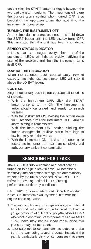
double click the START button to toggle between thetwo audible alarm options. The instrument will store the current alarm setting when turned OFF, thus becoming the operation alarm the next time the instrument is powered up.
TURNING THE INSTRUMENT OFFAt any time during operation, press and hold down the START button until the LED display turns OFF. This indicates that the unit has been shut down.
SENSOR STATUS INDICATORIf the sensor is damaged, every other one of the tachometer LED’s will light up visibly notifying the user of the problem, and then the instrument turns itself OFF.
LOW BATTERY INDICATORWhen the batteries reach approximately 10% of capacity, the rightmost tachometer LED will stay lit above the LO BAT legend.
CONTROLSingle momentary push-button operates all functions of the unit: • With the instrument OFF, click the START
button once to turn it ON. The instrument is automatically calibrated and ready to search for leaks.
• With the instrument ON, holding the button down for 3 seconds turns the instrument OFF. Audible alarm setting is remembered.
• With the instrument ON, double clicking the button changes the audible alarm from high to low intensity and vice versa.
• With the instrument ON, clicking the button once resets the instrument to maximum sensitivity and nulls out any ambient contamination.
The LS3000 is fully automatic and need only be turned on to begin a leak search. All necessary sensitivity and calibration settings are automatically selected by the unit’s advanced POWERSHIFT™software providing optimal leak searching performance under any conditions.
SAE J1628 Recommended Leak Search ProcedureNote: On automotive A/C systems, test with the engine not in operation.
1. The air conditioning or refrigeration system should be charged with sufficient refrigerant to have a gauge pressure of at least 50 psig/340kPa/3.4 BARwhen not in operation. At temperatures below 59°F/15°C, leaks may not be measurable, since this pressure may not be reached.
2. Take care not to contaminate the detector probe tip if the part being tested is contaminated. If the part is particularly dirty, or condensate (moisture)
SEARCHING FOR LEAKS
3
is present, it should be wiped off with a dry shop towel or blown off with shop air. No cleaners or solvents should be used, since the detector may be sensitive to their ingredients.
3. Visually trace the entire refrigerant system and look for signs of air conditioning lubricant leakage, damage, and corrosion on all lines, hoses, and components. Each questionable area should be carefully checked with the detector controls, service ports with caps in place, brazed or welded areas, and areas around attachment points and hold-down on lines and components.
4. Always follow the refrigerant system around in a continuous path so that no areas of potential leaks are missed. If a leak is found, always continue to test the remainder of the system.
5. At each area checked, the probe should be moved around the location at a rate no more than1-2 in/s (25 to 50mm/s), and no more than .2” (5mm) from the surface, completely around the position. Slower and closer movement of the probe greatly improves the likelihood of finding a leak.
6. An apparent leak shall be verified at least once by blowing shop air into the area of the suspected leak, if necessary, and repeating the check of the area. In cases of very large leaks, blowing out thearea with shop air often helps locate the exact position of the leak.
7. Leak testing to the evaporator core while in the air conditioning module shall be accomplished by turning the air conditioning blower on high for a period of 15 seconds minimum, shutting it off, then waiting for the refrigerant to accumulate in the case for ten minutes. Next, insert the leak detector probe into the blower resistor block or condensate drain hole if no water is present, or into the closest opening in the heating/ventilation/air conditioning case to the evaporator, such as the heater duct or a vent duct. If the detector alarm sounds, a leak apparently has been found.
8. Following any service to the refrigerant system, and any other service that disturbs the refrigerant system, a leak test of the repair and of the service ports of the refrigerant system should be done.
OPERATING TIPS• WINDY CONDITIONS: Locating leaks under windy
conditions may severely impede the leak searching process. Even very large leaks may be impossible to find as the escaping gas is quickly dissipated into the atmosphere. If necessary, fabricate a gas trap using aluminum foil around joints or fittings or otherwise shield the search area from the wind.
• WHEN TO RESET THE UNIT: It is necessary to reset the LS3000 during a leak search if the unit becomes fully saturated, multiple leaks are present or during the leak verification process.
• LEAK VERIFICATION: If a suspected leak is
4
indicated, verify several times by moving the sensor away from the leak area, resetting the unit and then back to the suspected leak. If the instrument indicates a leak three consecutive times, then you have found a leak.
MAINTENANCEThe ELIMINATOR™ LS3000 is designed to required a minimal amount of field maintenance. Periodic replacement of the unit’s sensor and batteries are the only maintenance needs.
• LOW BATTERY CONDITION: When the batteries reach approximately 10% of capacity, the rightmost LED of the tachometer indicator (above the LO BATsymbol) will energize. The other seven LEDs will continue to function as indicators of the leak’s relative size.
• CHANGING THE CCD SENSOR: The CCD sensor assembly consists of metal and plastic components. Do not attempt to remove one component from the other. Do not use solvents or cleaning solutions for cleaning the sensor. It should be replaced when air vents become clogged. Eventually, the sensor will need to be replaced. This condition is usually indicated by abnormal or erratic performance. Withthe unit OFF, install the new sensor as ILLUSTRATION 1 demonstrates. CPS recommends that you change the CCD sensor at the beginning of every cooling season and always have a spare sensor available for replacement in the field.
ILLUSTRATION 1
CCD SENSOR (LSXS3)WARNING: ONE PIECE DESIGN - DO NOT PULL APART!
CAUTION:
HIGH VOLTAGE MAY BE PRESENT AT END OF PROBE WHEN SENSOR IS REMOVED.
LS3000 SPECIFICATIONSSENSOR: State of the art Cold Cathode Discharge Diode.TYPES OF GASES: Sensitive to all halogenated refrigerants: HFC’s, CFC’s, HCFC’s. Sensitive to all halogenated vapors and gases such as SF6.SENSITIVITY: Fully automatic sensitivity selection with 6 visible LED range indicators. Maximum sensitivity allows detection of a 0.25 oz/yr (7 g/yr) leak of R-134a (HFC).
LEAK INDICATIONAUDIBLE ALARMS: Two user selectable audible alarm options (High and low intensity alarm tones)VISUAL ALARMS: TACHOMETER bar graph
5
display. Eight high intensity LEDs are arranged in a Tachometer-like display indicating leak intensity per the sensitivity range. GEARSHIFT display is arranged in a gearshift pattern. Seven LEDs indicate the current sensitivity range of the unit and subsequent leak size as follows:
GEAR LEAK SIZEN No Leak1 & 2 Small3 & 4 Medium5 & 6 Large
OPERATING TEMPERATURE: -18 to 60°C (0 to 140°F)
POWER: Three size ‘C’ alkaline batteries (NEDA/ANSI 14A)Continuous Operating battery life at 77°F (25°C):
High intensity alarm: 55 hrsLow intensity alarm: 75 hrs
Because the instrument turns itself off after 10 min. of inactivity, the actual useful battery life may be longer than stated. See Maintenance section for LOBAT conditions.DIMENSIONS: Instrument (Lx W xH): 10” x 2.3” x 2” 254mm x 59mm x 51mmPROBE: 14” (36.5cm) long, .25” (6.4mm) diameter, metal flex probe.WEIGHT: 1 lbs. 2 oz. (500 grams)
WARRANTY & REPAIR POLICYCPS® Products, Inc, guarantees that all products arefree of manufacturing and material defects for two years. If the equipment should fail during the guarantee period it will be repaired or replaced (at our option) at no charge. This guarantee does not apply to equipment that has been altered, misused, or returned solely in need of field service maintenance.This repair policy does not include equipment that is determined to be beyond economical repair. All products being returned for warranty repair must be accompanied by an original bill of sale and customer contact information.
6
Le modèle LS3000 est le premier détecteur de fuite électronique vraiment automatique au monde, n’ayant besoin d’aucune intervention d’opération pendant la recherche d’une fuite. Contrôlé par un logiciel exclusif POWERSHIFT™, le LS3000 adapte de façon continue et automatique les fonctions essentielles qui ont trait à sa sensibilité, procurant ainsi des résultats de détection sous toute condition.
GENERAL
• Le premier détecteur de fuite électronique vraimentautomatique au monde
• Connexions électroniques contrôlés par un microprocesseur
• Logiciel exclusif POWERSHIFT™
• Nouveau élément sensible ‘Cold Cathode Diode’ -Diode à cathode froide – ou CCD
• Résistance supérieure au contaminants de fond• Barre à LED style ‘tachymètre’ exclusive• Enveloppe forte et vraiment ergonomique • Vie de batteries de 75 heures au moins, s’éteint
automatiquement• Inclût un coffre dur, un élément sensible de
rechange et 3 batteries ‘C’ alkaline• Détecte TOUS les réfrigérants CFC/HCFC/HFC et
mélanges• Garantie : comme d’application• Approuvé SAE J1627 - CE
CARACTERISTIQUES
HAUT PARLEUR POUR SIGNAL FORT
BARRE A LEDS STYLE TACHYMETREPour une indication exacte
de la source de la fuite
LEDS INDICATEURS DE TAILLEPour une indication approximative
de la taille d’une fuite LOGICIEL ‘POWERSHIFT’
Contrôle automatique tous les compositions relatives à la sensibilité, facilitant ainsi
la manutentionOPERATION PAR UNE TOUCHEPour remise à zéro, signal
auditif, marche/arrêt
CARACTERISTIQUES D’EMPLOIMISE EN MARCHEUne dépression de la touche.
REMISE A ZEROPendant toute l’opération, une dépression de la touche remettra le détecteur à sa sensibilité maximale, tenant compte des conditions ambiantes.
7
CHOIX EN SIGNAUX AUDIBLESLe LS3000 inclût 2 signaux d’alarme au choix de l’utilisateur. Possibilité de alterner à chaque instant pendant l’opération par une double dépression sur la touche. L’instrument maintiendra le dernier signalchoisi lors de la mise en marche.
ETEINDRE L’INSTRUMENTA chaque instant pendant l’opération, il suffit de maintenir la dépression sur la touche pour voir éteindre les LED et ainsi l’instrument.
INDICATION DE L’ETAT DE L’ELEMENTSENSIBLEQuand le ‘senseur’ est endommagé, tous les LED du tachymètre illumineront, avertissant ainsi l’utilisateur du problème, puis l’instrument s’éteindra.
INDICATION BATTERIES AFFAIBLIESQuand les batteries sont a +/- 10% de leur capacité, l'indicateur LED, à la droite,(au dessus du LO BATmessage), s'allumera en continu.
OPERATIONUne seule touche d’opération instantanée :• Eteint, l’instrument est mis en marche en appuyant
une fois sur la touche. Une remise en état automatique le rend prêt pour détection.
• En marche, l’instrument est arrêté en appuyant sur la touche pendant 3 secondes. Le dernier signal audible est mémorisé.
• En marche, l’instrument passe d’un signal sonore à l’autre en appuyant deux fois sur la touche.
• En marche, l’instrument est remis en sa sensibilité maximale tenant compte de la contamination de fond en appuyant une fois sur la touche.
LA RECHERCHE DES FUITESLe LS3000 est entièrement automatique et ne nécessite que d’être mis en marche pour pouvoir commencer la recherche. Tous les sensibilités et les mises à zéro sont sélectionnées automatiquement par le logiciel avancé POWERSHIFT™ qui fournit unerecherche optimale en toute condition.
Procédure de détection de fuites selon les normes SAE J1628. (Société Américaine des Ingénieurs dansle secteur automobile) Pour la détection dans un système de conditionnement d’air mobile: éteindre le moteur.
1. Le système réfrigéré ou air conditionné doit être chargé de suffisamment de réfrigérant pour avoir une pression minimale de 3.5 Bar au manomètre, système éteint. Aux températures inférieures à 15°C des fuites pourraient être introuvables, comme cette pression ne serait pas obtenue.
2. Veiller à ne pas salir la sonde du détecteur lors de la détection auprès des composants contaminés. Il est préférable de nettoyer les contaminations
8
excessives et rincer l’humidité du composant avec une serviette ou de l’air comprimé. Ne pas utiliser des solvants ou des nettoyants, comme le détecteur pourrait les détecter.
3. Vérifier visuellement le système entier et chercher des indications de fuite d’huile, dégâts, corrosion sur tubes, flexibles et composants. Vérifier avec précaution chaque endroit douteux par la sonde du détecteur, comme également tous les raccords et raccordements du système, soudures et composants.
4. Pendant la détection, suivre le système sans interruption pour ne pas omettre certaines fuites potentielles. Quand une fuite est trouvée, toujours continuer à tester le reste du système.
5. La sonde du détecteur à passer les endroits de vérification à une vitesse ne pas excédant 2,5 à 5 cm par seconde et à une distance de 0,5 cm! Un passage plus lent et plus proche augmentera considérablement la chance de trouver une fuite.
6. Une fuite apparente sera vérifiée au moins une fois par l’application d’air comprimé. Dans le cas d’une très grande fuite, l’air comprimé aide à mieuxlocaliser la fuite exacte.
7. La vérification de l’intérieur d’un évaporateur situé dans le système est faite ainsi : mettez le ventilateur en position maximale pendant au moins15 secondes, alors éteignez-le pour attendre l’accumulation du réfrigérant pendant 10 minutes. Puis entrez la sonde du détecteur près de la résistance ou de l’orifice de condensation (évitez l’eau !), ou dans les ouvertures proches de l’évaporateur, comme le drainage de la chaleur ou du vent.
8. Quand le détecteur réagit, probablement une fuite a été trouvée. Après tout service au système réfrigéré, ou tout autre service perturbant le système réfrigéré, il est nécessaire d’effectuer une détection de fuite aux accès ou aux réparations faites.
CONSEILS POUR L’UTILISATEUREndroits ventilés: Il est a éviter de faire le controle,dans des endroits avec des courants d’air trop forts.Même pour des fuites importantes, les courants d’air peuvent dérègler sérieusement les mesures. Couvrez donc ces endroits afin d’obtenir une espace stable.Remise a zero: Il est nécessaire de remettre le LS3000 a zero (effacer la mémoire) quand une saturation totale a été enregistrée, ou en cas de doute de la concentration enregistrée.Contrôle de fuite: quand une fuite éventuelle est réperé : éloigner le détecteur de l’endroit. Effacerla mémoire et revenir à l’endroit. Répèter ceci jusqu’à trois fois. Si a chaque reprise vous notez un signal, vous avez répéré l’endroit de la fuite.
9
ENTRETIENLe ELIMINATOR™ LS3000 a été conçu pour ne demander qu’un minimum d’entretien sur le champs. Remplacer les batteries et l’élément sensible: voilà les seules besoins d’entretie!
• Batterie affaiblie: Quand les batteries sont a +/- 10% de leur capacité, l'indicateur LED, à la droite, (au dessus deu LO BAT message), s'allumera en continu. Les sept autres LED continueront a fonctionner comme indicateurs de fuite.
• Rechange de l’élément sensible CCD:Le ‘senseur’ CCD est composé de façon permanenteen 2 parties, l’une métallique et l’autre plastique. N’essayez pas de les diviser. N’utilisez pas des solvants ou des détergents pour nettoyer le senseur. Il devrait être remplacé quand les orifices d’entrée sont obstruées. Finalement, l’élément sensible devra être changé. Ce besoin est normalement indiqué par une réaction anormale ou erratique. Installez le nouveau senseur avec le détecteur éteint, comme illustré (1). CPS® conseille de changer l’élément sensible devant chaque saison R/AC et d’en avoir toujours une deuxième pour remplacement sur le champs.
ILLUSTRATION 1
Element Sensible CCD (LSXS3)
CAUTION:
IL PEUT Y AVOIR UN HAUT VOLTAGE AU BOUT DU BRAS FLEXIBLE PENDANTL’ENLEVEMENT DE L’ELEMENT SENSIBLE
AVERTISSEMENT: CONSTRUIT EN UNE PIECE – NE PAS SEPARER !
SPECIFICATIONS DU LS3000ELEMENT SENSIBLE: diode à décharge de cathode froideTYPES DE REFRIGERANTS: sensible à tous les réfrigérants halogènes: HFC, CFC & HCFC, comme à tous les mélanges et gaz halogènes comme le SF6.SENSIBILITE: sélection entièrement automatique de sensibilité incluant 6 indications de plage LED.Sensibilité maximale permet la détection d’une fuitede 7g/an de R134a.INDICATION DE FUITESIGNAL AUDIBLE: 2 niveaux de signal d’alarme à sélectionner (basse ou haute intensité)SIGNAL VISUEL: Barrette illuminant style tachymètre: indiquant l’intensité d’une fuite par 8 LED de haute intensité Indication style boîte à vitesses: 7 LED indiquent la plage actuelle de sensibilité et la taille de la fuite qui en suit, comme indiqué ci-dessous:
10
Vitesse Taille de fuiteN pas de fuite1 & 2 petite3 & 4 normale5 & 6 grande
PLAGE D’OPERATION: -18° à 60°C (0 à 140°F)ALIMENTATION: 3 batteries ‘C’ Alkaline 14 AVie de batteries - travail continu à 25°C (77°C)
Signal haute intensité: 55 hSignal basse intensité: 75 h
Comme l’instrument s’éteint automatiquement après 10 min. d’inactivité, il se peut que la vie de batteries pratique sera plus longue qu’indiquée. L’utilisateur est averti des batteries arrivant à environ 10% de leur vie utile quand les LED style tachymètre se balayent de l’un côté à l’autre.DIMENSIONS: de l’instrument : 254 x 59 x 51mmSONDE métallique: longueur 356mm,épaisseur 6.4mmPOIDS: 500 g
GARANTIE & REPARATIONS La société CPS® Products, Inc garantit que tous ses produits sont exempts de défauts de fabrication ou de matières au propriétaire d’origine pendant un an à compter de la date de l’achat. Si l’appareil tombe en panne durant la période de garantie, il sera réparé ou remplacé (à notre convenance) gratuitement. Cette garantie ne s’applique pas aux appareils qui ont été modifiés, dont l’usage a été détourné ou qui nous sont retournés alors qu’ils ne nécessitent qu’un entretien de routine. Tout appareil réparé bénéficiera d’une garantie supplémentaire de 90 jours. Cette garantie ne s’applique pas aux appareils pour lesquelsl’estimation du coût de réparation dépasserait le prix du neuf.
11
LS3000 ELIMINATOR™ ist das weltweit einzige VOLLAUTOMATISCHE elektronische Lecksuchgerät.Keine Einstellungen, oder Mutmassungen während der Lecksuche erforderlich. Ausgedacht durch eine exklusives POWERSHIFT™ Software, passt sich der LS 3000 kontinuierlich u. automatisch den kritischen Empfindlichkeiten an, so dass unter allen Umständen immer ein optimales Lecksuchergebniss erreicht wird.
ALLGEMEINE BESCHREIBUNG
• Das erste vollautomatische Lecksuchgerät in der Welt• Patentiertes Schaltsystem, kontrolliert durch einen
Technologie• Besonders widerstandsfähig gegen hintergründige
Luftverschmutzungen.• Exklusive LED Indikation gemäss Tachometer Typ• Solides, ergonomisches Gehäuse• Batterie-Lebensdauer: ca. 75 Std. bei Einsatz im LO
Sensitivbereich, Selbstausschaltung nach 10 Min.• Lieferumfang: Stabiler Tragekoffer, Ersatz-CCD
Sensor mit integrierten Wasserdampf - Filter u. 3 Stück. Alkaline Batterien, Typ – C -.
• Alle CFC, HCFC u. HFC Kältemittel und Mischungen können aufgespürt werden
• Garantiezeit 1 Jahr.• Zertifiziert nach Standard SAE J 1627
MERKMALE
LAUTSPRECHER mit hoher Kapazität.
8 LED´s Typ TachometeranzHier erkennen Sie die genaue
Stelle wo einer Leckage sein könnte.
6 LED´s nach dem Prinzip ein Gangschaltung.
Zeigt dem Anwender die GrössMöglichen Leckage.
POWERSHIFT™ SOFTWAREKontrolliert automatisch die
Einstellungen der erforderlichenEmpfindlichkeit, damit die
Lecksuche vereinfacht wird
TASTEFür EIN - u. AUS schalten, Alarm
Einstellung, Neu justieren.
Bedienung des Gerätes wie folgt:EINSCHALTEN1 x ( Einmal ) auf die Taste drücken.
JUSTIEREN und WIEDEREINSTELLUNGWährend der Lecksuche ist es möglich, das Gerät vonneuem auf seine höchste Empfindlichkeit einzustellen,
12
bzw. auf die hintergründigen Luftverschmutzungen zu justieren. Drücken Sie einfach nochmals die TASTE.
ALARMTON einstellenDas LS 3000 enthält 2 wählbare akustische Alarmsignale. Es ist möglich, während die Operation von einen zum
anderen Ton zu schalten. Einfach zweimal kurz auf die Taste drücken. Der zuletzt aktivierte Alarmton wird beim Ausschalten gespeichert und beim wieder Einschalten auch wieder aktiviert.
AUSSCHALTEN des GerätesDie AN / AUS – Taste ca. 3 Sekunden gedrückt halten bis keine Funktion mehr vorhanden ist.
SENSOR ZustandsanzeigeWenn der Sensor beschädigt, oder verschlissen sein sollte, leuchten alle LED´s von der Tachometeranzeige als Warnung auf. Kurz danach schaltet sich das Gerät selbständig aus.
LEERE BATTERIE AnzeigeWenn die Batterien nur noch ca. 10% der Ladek apazität haben, leuchten die LED´s von der Tachometeranzeige von links nach rechts auf und weisen darauf hin, daß die Batterien jetzt unbe-dingt gewechselt werden müssen.
Kurzerklärung der Einzel – TASTE• Mit einer Taste wird die ganze Bedienung wie folgt
gesteuert: Zum Einschalten: Die Taste einmal drücken. Das Gerät stellt sich automatisch auf die Empfindlichkeit ein und ist sofort Einsatzbereit.
• Zum Ausschalten: Die Taste ca. 3 Sekunden gedrückt halten. Der zuletzt eingestellte Alarmton wird gespeichert.
• Alarmtonwechsel: Während der Lecksuche kann der Alarmton verändert werden. Drücken Sie kurz hintereinander 2 x auf die Taste.
• Nullstellung und Justierung: Während der Leck suche kann man das Gerät wieder auf seine höchste Empfindlichkeit einstellen, bzw. durch Nullstellung die hintergründige Luftverschmutzung eliminieren. Einfach 1 x auf die Taste drücken.
Wichtige Hinweise für die LECKSUCHEAchtung: Empfohlene Hinweise nach SAE J 1628 Bei einer Automobil-Klimaanlage ( A/C ) keine Lecksuche vornehmen solange der Motor läuft.
1. Das System der Kälte – o. Klimaanlage sollte ein ausreichendes Volumen an Kältemittel haben und der Druck in der Anlage sollte im ruhenden Zustand ca. 3,50 bar aufweisen. Bei Temperaturen unterhalb von 15 °C und einem Druck in der Anlage unter 3,50 bar sind eventuelle Leckagen nicht, oder kaum noch meßbar.
2. Bitte unbedingt darauf achten, daß die Spitze von dem Sensorgehäuse frei von jeglichen Schmutz ist. Selbst kleinste Verstopfungen können zu einem Fehlalarm führen.Sollte das Sensorgehäuse durch Schmutzpartikel, oder der Kopf an diesem Gehäuse durch starke Feuchtigkeit beeinträchtigt worden sein, bitten wir unbedingt folgendes zu beachten:Äußere Reinigung von dem Sensorgehäuse nur mit einem sauberen Lappen vornehmen. Innere Reinigung mit sauberer Preßluft, jedoch mit weichem Druck. -Auf vollem Durchgang der Düsen achten. Die Kontaktfläche für den Sensor mit einem weichen Lappen säubern. Diese 4 Schritte empfehlen wir in regelmäßigen Abständen, ca. 1 x pro Woche, ungeachtet der Verschmutzung zu wieder - holen, denn damit haben Sie eine gute Vorsorge getroffen.Keine Reinigungs-oder Lösungsmittel verwenden!
13
3. Augenscheinliche Betrachtung des gesamten Kälte- oder Klimaanlagensystems auf jegliche Zeichen einer Leckage von Ölaustritt, Beschädigungen und Korrosionen an den Leitungen, Schläuchen und Komponenten. Jede fragwürdige Stelle sollten Sie sorgfältig mit der Sensorspitze von dem Lecksuchgerät aus einer Entfernung von ca. 5 mm abtasten, speziell alle Verschraubungen, Schläuche und Kupplungen, sowie alle Verbindungen.
4. Folgen Sie immer kontinuierlich den Weg in dem System mit der Meßspitze von dem Lecksuchgerät, so das keine Möglichkeit ausgelassen wird eine Leckage zu entdecken. Sollten Sie eine Leckage ausfindig gemacht haben und das Lecksuchgerät einen Alarmton aussendet, so wiederholen Sie mehrfach mit der Sensorspitze die Lecksuche an der Stelle wo vorher der Alarmton ertönte, um sich von der genauen Stelle der Undichtigkeit zu überzeugen.
5. Die Lecksuche mit der Meßspitze von dem Lecksuch-gerät darf nur mit einer Geschwindigkeit von max. 25 bis 50mm pro Sekunde erfolgen und die Meßspitze sollte nicht mehr als 5 mm von der Oberfläche der abzusuchenden Fläche entfernt sein. Noch langsameres Bewegen und mehr Nähe an die Oberfläche der abzusuchenden Stellen erhöht die Wahrscheinlichkeit eine Leckage besser zu erkennen.
6. Eine wahrscheinliche Leckage läßt sich noch besser sicherstellen, wenn Sie z.B. mit Preßluft die Gegend der vermutlichen Leckage abblasen. Wenn notwendig, wiederholen Sie diesen Vorgang. Im Fall einer sehr großen Leckage können Sie mit dieser Methode die Undichtigkeit schon sehr oft durch Augenschein entdecken.
7. Eine Lecksuche im Inneren des Verdampfers sollte wie folgt ausgeführt werden: Lassen Sie den Lüfter von dem Verdampfer mindestens ca. 15 Sekunden mit einer hohen Geschwindigkeit laufen. Schalten Sie den Lüfter aus und warten ca. 10 Minuten damit sich das Kältemittel ansammeln kann. Als nächstes stecken Sie dann die Meßspitze von dem Lecksuchgerät in die Lamellen von dem Verdampfer, oder in den Abfluß von dem Kondens-wasser, jedoch ist unbedingt darauf zu achten, daß die Meßspitze nicht mit Wasser in Berührung kommt. Weiterhin setzen Sie die Suche in dem Kasten von dem Heizungs-u.Lüftungssystem fort. Wenn das Lecksuchgerät dann einen Alarmton ertönen läßt, haben Sie die wahrscheinliche Leckage ausfindig gemacht.
8. Reparieren Sie alle defekten Versorgungsleitungen von dem Klima- oder Kältesystem und überprüfen Sie gleichzeitig alle anderen Systeme auf Beschädigungen. Nach der Reparatur sollte unbedingt noch einmal eine Lecksuche an der reparierten Stelle vorgenommen werden, damit Sie sicher sein können, eine wirklich dichte Anlage vorzufinden.
Einige wichtige Hinweise und Ratschläge
• Windige Umgebung: Starten Sie nicht mit der Lecksuche in einer windigen Umgebung. Dieses ist möglich, wenn ein Ventilator Läuft, oder andere Witterungseinflüsse vorherrschen. Das flüchtige Gas verteilt sich in die Atmosphäre und Eine genaue Lecksuche ist dann nicht mehr möglich. Schirmen Sie die Stellen wo Sie eine Lecksuche vor-Nehmen müssen mit einer Folie, oder einen anderen Windschutz ab und stellen sicher, daß keine Luft-strömungen die Lecksuche beeinflussen können.
14
INSTANDHALTUNGDas Lecksuchgerät LS3000 ist so entwickelt worden, dass nur eine geringe Aufmerksamkeit diesem Gerät gewidmet werden muß. Sauberkeit und regelmässigerAustausch von dem Sensor und der Batterien ist dieeinzige benötigte vorsorg-liche Instandhaltung.
• Leere Batterien: Wenn die Batterien nur noch ungefähr 10% Ihrer Lade-Kapazität erreicht haben,fangen die LED´s an der Tacho-Meteranzeige von links nach rechts aufzuleuchten. Bitte jetzt unbedingt alle Batterien austauschen.
• Austausch des CCD Sensors: der CCD Sensor besteht aus Metall- und Plastikkomponenten welches eine geschlossene Einheit ist. VersuchenSie es nicht, beide Komponente auseinander zu ziehen. Verwenden Sie keine chemischen Reinigungs- oder Lösungsmittel zum reinigen desSensors. Der Sensor soll ausgetauscht werdenwenn die Ventilationslöcher verstopft sind. Sollte der Sensor einmal ausgetauscht werden müssen,dann bitte wie auf der Abbildung zu erkennen, den neuen Sensor wieder aufschrauben.Einen defekten, oder verschlissenen Sensor erkennen Sie an unregelmässige Klick-Geräusche.Den Sensor nur bei ausgeschaltetem Gerät wechseln! Bei regelmäßigem Gebrauch empfehlen wir den Sensor 2 x im Jahr zu wechseln. Weiterhin sollten Sie immer einen Ersatzsensor mit sich Führen, sowie 3 Stück von den vorgeschriebenen Batterien.
• Wann sollten Sie das Gerät neu justieren: Bei starker hintergründiger Luftverschmutzung, oder Mehrerer vorhandenen gleichzeitigen Leckagen kann es notwendig sein, dass Sie das Gerät neu justieren müssen. Drücken Sie nochmals, aber nur 1 x die Taste.
• Eine Leckage sicherstellen: Wenn eine vermeintliche Leckage ausfindig gemacht Worden ist, überprüfen Sie diese einige Male wie folgt: Nehmen Sie die Sensorspitze von der Leckage weg, drücken Sie die Taste einmal (Reset) zum justieren des Gerätes. Führen Sie jetzt die Sensorspitze nochmals zu der gleichen Stelle der Leckage. Wenn 3 mal nacheinander der Alarmton ertönt, dann können Sie sicher sein, dass hier eine Leckage ist.
ABBILDUNG 1
CCD SENSOR (LSXS3)
Wichtiger Hinweis: Sensor und Kunststoff – Sensorschutzhülle bestehen Aus einem zusammenhängenden Teil. NICHT ABBRECHEN!
WARNUNG:
Bei abgeschraubten Sensor kann am Kontaktpunkt von dem Sensor eine hohe Spannung vorhanden
sein, welche jedoch nicht gefährlich ist.
15
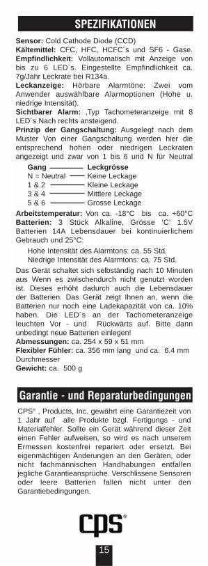
SPEZIFIKATIONENSensor: Cold Cathode Diode (CCD)Kältemittel: CFC, HFC, HCFC´s und SF6 - Gase.Empfindlichkeit: Vollautomatisch mit Anzeige von bis zu 6 LED´s. Eingestellte Empfindlichkeit ca. 7g/Jahr Leckrate bei R134a.Leckanzeige: Hörbare Alarmtöne: Zwei vom Anwender auswählbare Alarmoptionen (Hohe u. niedrige Intensität).Sichtbarer Alarm: ‚Typ Tachometeranzeige mit 8 LED´s Nach rechts ansteigend.Prinzip der Gangschaltung: Ausgelegt nach dem Muster Von einer Gangschaltung werden hier die entsprechend hohen oder niedrigen Leckraten angezeigt und zwar von 1 bis 6 und N für Neutral
Gang LeckgrösseN = Neutral Keine Leckage1 & 2 Kleine Leckage3 & 4 Mittlere Leckage5 & 6 Grosse Leckage
Arbeitstemperatur: Von ca. -18°C bis ca. +60°CBatterien: 3 Stück Alkaline‚ Grösse ‘C’ 1.5V Batterien 14A Lebensdauer bei kontinuierlichemGebrauch und 25°C:
Hohe Intensität des Alarmtons: ca. 55 Std. Niedrige Intensität des Alarmtons: ca. 75 Std.
Das Gerät schaltet sich selbständig nach 10 Minuten aus Wenn es zwischendurch nicht genutzt worden ist. Dieses erhöht dadurch auch die Lebensdauer der Batterien. Das Gerät zeigt Ihnen an, wenn die Batterien nur noch eine Ladekapazität von ca. 10% haben. Die LED´s an der Tachometeranzeigeleuchten Vor - und Rückwärts auf. Bitte dann unbedingt neue Batterien einlegen!Abmessungen: ca. 254 x 59 x 51 mmFlexibler Fühler: ca. 356 mm lang und ca. 6.4 mmDurchmesserGewicht: ca. 500 g
Garantie - und ReparaturbedingungenCPS® ‚ Products, Inc. gewährt eine Garantiezeit von 1 Jahr auf alle Produkte bzgl. Fertigungs - und Materialfehler. Sollte ein Gerät während dieser Zeit einen Fehler aufweisen, so wird es nach unserem Ermessen kostenfrei repariert oder ersetzt. Bei eigenmächtigen Änderungen an den Geräten, oder nicht fachmännischen Handhabungen entfallen jegliche Garantieansprüche. Verschlissene Sensoren oder leere Batterien fallen nicht unter denGarantiebedingungen.
16
ESPECIFICACIONESEL ELIMINATOR™ modelo LS3000 es el primer y único detector de fugas verdaderamente automático en el mundo, eliminando la necesidad de intervención por parte del del usuario durante la búsqueda de fugas. Usando el programa de control POWERSHIFT™desarrollado por CPS Products, el modelo LS3000 ajusta todos los parámetros de operación continuam-ente y de modo automático, eliminando así la necesidad de ajustes manuales para obtener resultados óptimos en todas las búsquedas.
CARACTERISTICAS• Primer detector verdaderamente automático en el
mundo.• Circuito patentado de control computarizado• Programación POWERSHIFT™ exclusiva de CPS• Sensor de último diseño tipo CCD• Inmunidad superior a contaminación de fondo• Indicadores exclusivos tipo TACOMETRO • Diseño ergonómico y a la vez resistente para
comodidad del operador.• Eficiente uso de las baterías, con por lo menos 75
horas de operación y •apagado automático• Incluidos maletín, sensor CCD de repuesto y tres
baterías tipo “C”alcalinas• Rápidamente detecta todos los refrigerantes CFC/
CFC/HFC y las mezclas.• Garantía de dos años• Certificado bajo SAE J1627 y CE
Bocina de Alto Volumen
Indicador LED tipo TACOMETRO de 8 niveles
señala con precisión el lugar de la fuga
Indicador lumínico de magnitudpermite rápido estimado de la
gravedad de la fuga
Programación POWERSHIFT™controla automáticamente la
sensibilidad y otros parámetros, simplificando el uso
SOLO UN BOTON SE NECESITAPara reajuste, cambio de
alarmas ó apagado
OPERACIONENCENDIDOSimplemente oprima el botón START.
REAJUSTEEn cualquier momento durante la búsqueda de fugas, oprimiendo el botón START momentáneamente, reajusta el instrumento a su sensibilidad más alta,
17
anulando al mismo tiempo la influencia del nivel de contaminación existente.
CAMBIO DE ALARMASEl modelo LS3000 utiliza dos sonidos distintos para anunciar la presencia de fugas, uno de alta intensidad y otro de baja intensidad. Para activar la alarma complementaria, simplemente oprima el botón STARTmomentáneamente dos veces seguidas. La alarma en uso cuando se apaga el instrumento se almacena en una memoria interna y es la que aparece cuando el instrumento se enciende la próxima vez.
APAGADOSimplemente mantenga oprimido el botón STARTpor unos segundos hasta que la alarma lumínica se apague
INDICADOR DEL ESTADO DEL SENSORCuando el sensor ya no funciona adecuadamente, las luces del indicador TACOMETRO se encienden una sí y otra nó por unos segundos y luego el instrumento se apaga automáticamente evitando falsas alarmas.
INDICADOR DE ESTADO DE LA BATERIACuando las batería llegan a un nivel de 10% de su capacidad, el indicador a la extrema derecha del TACOMETRO se enciende. Este indicador es el que está encima del símbolo LO BAT.
CONTROL DE FUNCIONESUna ligera presión del botón START es todo lo necesario:
• Cuando el instrumento está apagado, oprimiendo el botón START lo enciende y lo ajusta a las condiciones óptimas para buscar fugas.
• Cuando el instrumento está encendido, oprimiendo el botón START por unos segundos lo apaga. La alarma en uso se queda almacenada para la próxima jornada de uso.
• Cuando el instrumento está en operación, oprimiendo el botón START dos veces cambia la alarma de sonido.
• Cuando el instrumento está en uso, oprimiendo el botón de START una vez, lo reajusta al punto de más sensibilidad y elimina la influencia de la contaminación ambiental.
BUSCANDO FUGASEl modelo LS3000, siendo completamente automático, sólo necesita ser encendido para ser usado. Todos los parámetros necesarios para una óptima búsqueda de fugas se ajustan automáticamente por medio de la programación POWERSHIFT™.
Procedimiento SAE J1628 Para Búsqueda de Fugas Nota: En sistemas con motores de combustión interna—automóviles, camiones, etc., apague el motor antes de buscar la fuga.
18
1. Cargue el sistema con suficiente gas como para obtener una presión de no menos de 50 psig/340kPa/3.4 BAR cuando esté apagado. A temperaturas por debajo de 59°F/15°C, la detección de fugas puede ser imposible por baja presión.
2. Es preciso prevenir la contaminación del sensor ya sea con materias sólidas ó con condensación. Si el área de búsqueda se encuentra muy sucia, ó si está cubierta de agua, use un paño ó aire comprimido para limpiarla. Cuidado de no usar solventes que puedan producir falsas alarmas del instrumento.
3. Haga una inspección visual de todo el sistema; busque principalmente en las áreas donde haya signos de lubricante, ó corrosión en las líneas, mangueras y componentes. Las áreas cuestionables se deben compr-obar con el detector de fugas,particularmente los controles, compuertas de servicio con tapaderas, soldaduras y puntos de anclaje.
4. Inspeccione el sistema siguiendo el paso normal de refrig-erante para no saltarse ningún elemento. Si se encuentra una fuga, inspeccione el resto del sistema siempre termine de revisar el resto del sistema.
5. Inspeccione cada área barriendo el sensor a una velocidad entre 1 y 2 pulgadas (25 a 50mm) por Segundo, y a una distancia de no más de .2” de pulgada (5mm). Barridos más lentos y más cercanos a las áreas sospechosas aumentan las probabilidades de encontrar las fugas.
6. Para verificar la presencia de una fuga, primero sople aire comprimido sobre al área y vuelva a barrerla con el detector. En caso de fugas muy intensas, ventilando el sitio con aire comprimido ayuda a precisar la localización de la fuga.
7. Para buscar fugas en el evaporador, primero encienda el ventilador por un mínimo de 15 segundos, apáguelo y espere unos 10 minutos para dejar que el refrigerante se acumule en la caja del evaporador. Inserte el sensor por el bloque de fusibles ó por el drenaje, si no hay acumulación de agua. También se puede introducir por uno de los conductos de aire ó o calefacción. Si el detector produce una alarma, existe una alta probabilidad de que haya una fuga en el evaporador.
8. Después de efectuar una reparación cualquiera en el sistema, es necesario verificar que no se hayan producido fugas en área donde se trabajó o en las compuertas de servicio.
TECNICAS• SITIOS DE MUCHO VIENTO: La búsqueda de fugas se
dificulta cuando hay condiciones de mucho viento, ya que el gas que se escapa se disipa rápidamente. Bajo estas condiciones es necesario aislar el área sospechosa utiliz-ando papel de aluminio u otro material similar para formar un bolsón alrededor de juntas, accesorios y demás sitios donde se pueda producir una fuga.
• CUANDO HACER UN REAJUSTE: Se debe hacer un reajuste del instrumento cuando este se haya saturado debido a una fuga muy intense, cuando se trata de fugas múltiples, ó durante el proceso de verificación.
• VERIFICANDO LA FUGA: Una vez que el instrumento ha producido una alarma, la presencia de la fuga se debe verificar moviendo el sensor repetidamente sobre el sitio donde sonó la alarma, si esta suena tres veces seguidas sobre el mismo sitio la fuga ha sido encontrada.
19
MANTENIMIENTODebido a la alta confiabilidad del diseño, el ELIMINATOR™ modelo LS3000 requiere un mínimo de mantenimiento; siendo necesario solamente cambiar el sensor y las baterías.
• CONDICION DE BAJA BATERIA: Al llegar la batería al 10% de su capacidad, el indicador lumínico en la extrema derecha del TACOMETRO-el que esta colocado encima del símbolo—se enciende para notificar la condición. Los otros siete indicadores mantienen su función normal.
• COMO CAMBIAR EL SENSOR CCD: El sensor consiste de partes plásticas y de metal, no se pueden separar. Tampoco use substancias cáusticas o disolventes para limpiarlo. Si las ranuras de ventilación se tupen, el sensor se debe cambiar. De la misma manera, cuando el sensor comienza a dar indicaciones erráticas, debe ser reemplazado, cuidando de apagar el instrumento y de colocar el nuevo sensor de la maneraindicada en la FIGURA 1. Recomendamos que el sensor se cambie al comienzo de cada temporada y que siempre se mantenga uno a mano para efectuar el reemplazo en cualquier lugar.
FIGURA 1
CCD SENSOR (LSXS3)AVISO: UNA SOLA PIEZA - NO SEPARE!
AVISO:
EXISTE LA POSIBILIDAD DE ENCONTRAR ALTO VOLTAJE EN LA PUNTA DE LA VARILLA DE PRUEBA FLEXIBLE CUANDO
SE DESCONECTA EL SENSOR.
ESPECIFICACIONES PARA EL LS3000SENSOR: Descarga en Diodo de Cátodo FríoTIPOS DE GASES DETECTABLES: Sensible a todos los tipos de refrigerantes halogenados: HFC’s, CFC’s, HCFC’s. También sensible a todo tipo de gas o vapor halogenado como SF6.SENSIBILIDAD: Selección automática mostrada por 6indicadores lumínicos. Máxima sensibilidad permite detectar por lo menos una fuga de 0.25oz/yr (7 g/yr) de R-134ª (HFC) INDICADORESALARMA AUDIBLE: Alarma audible de dos niveles de intensidad que pueden ser seleccionadas por el usuario.ALARMA VISUAL: Indicador lumínico tipo TACOMETRO de 8 niveles que indica la magnitud de la fuga dentro de uno de los 7 rangos de operación. Indicador lumínico tipo CAJA DE CAMBIOS anuncia el nivel de operación automáticamente seleccionado por el instrumento. Los siete indicadores de esta CAJA DE CAMBIOS representan lo siguiente:
VELOCIDAD FUGANeutro Sin Fuga1 & 2 Fuga pequeña3 & 4 Fuga mediana5 & 6 Fuga grande
20
POLITICA DE GARANTIA Y REPARACIONCPS® Products, Inc. garantiza que todos sus productos estan libres de defectos en su fabricación y en sus materiales por un año. Si el equipo fallara durante el tiempo de garantía sera reparado o reemplazado (a nuestra opción) sin costo alguno. Esta garantía no se aplica a equipos que han sido alterados, mal usados o retornados y que solamente requerian de un servicio y mantenimiento en el lugar mismo. Esta política de reparación no incluye equipos en los cuales se determina que la reparación sera mas costoza que la unidad misma. Todos los productos a ser regresados para reparación en garantía deben de estar acompañados de la factura de venta original y la información completa del cliente.
BATERIAS: Tres de tipo ‘C’ alcalinas (NEDA/ANSI14A) Operación continua a 25°C (77°F)
Alarma de alta intensidad: 55 hrsAlarma de baja intensidad: 75 hrs
Como que el instrumento se apaga automáticamente en 10 minutos, la vida de las baterías puede ser mucho más. Véase la sección de Mantenimiento correspondiente.DIMENSIONES: Instrumento (L x A x Alt.): 10” x 2.3” x 2” 254mm x 59mm x 51mmVARILLA FLEXIBLE: 14” (36.5cm) long, .25” (6.4mm) diámetro.PESO: 1 lbs. 2 oz. (500 g)