78
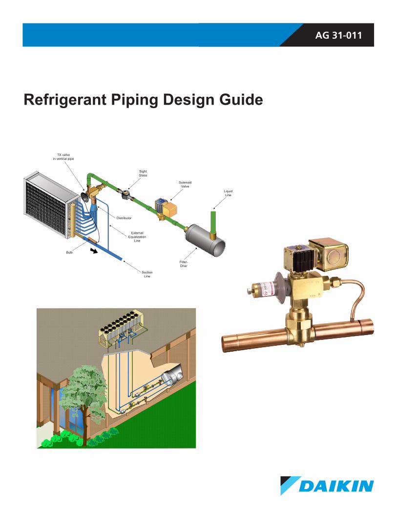
AG 31-011 Refrigerant Piping Design Guide TX valve in vertical pipe Sight Glass Solenoid Valve Liquid Line Filter- Drier Distributor External Equalization Line Suction Line Bulb
AG 31-011
Refrigerant Piping Design Guide
TX valvein vertical pipe
SightGlass
SolenoidValve
LiquidLine
Filter-Drier
Distributor
ExternalEqualization
Line
SuctionLine
Bulb

AG 31-011 • REFRIGERANT PIPING DESIGN 2 www.DaikinApplied.com
The information contained within this guide represents the opinions and suggestions of Daikin Applied. Equipment, and the application of the equipment and system suggestions are offered by Daikin Applied as suggestions and guidelines only, and Daikin Applied does not assume responsibility for the performance of any system as a result of these suggestions. The system engineer is responsible for system design and performance.
Introduction . . . . . . . . . . . . . . . . . . . . . . . . . . . . . . . . . . 3Audience . . . . . . . . . . . . . . . . . . . . . . . . . . . . . . . . . . . 3Using This Guide. . . . . . . . . . . . . . . . . . . . . . . . . . . . . 3
How to Determine Equivalent Length . . . . . . . . . . 3Refrigerant Piping . . . . . . . . . . . . . . . . . . . . . . . . . . . . 4Refrigerant Piping Design Check List . . . . . . . . . . . . . 5
Product Information . . . . . . . . . . . . . . . . . . . . . . . . . 5Jobsite Information. . . . . . . . . . . . . . . . . . . . . . . . . . 5
Typical Refrigerant Piping Layouts . . . . . . . . . . . . . . 6Piping Design Basics . . . . . . . . . . . . . . . . . . . . . . . . . . 9
Pressure Drop and Temperature Change . . . . . . . . 9Liquid Lines . . . . . . . . . . . . . . . . . . . . . . . . . . . . . . . . 10Suction Lines. . . . . . . . . . . . . . . . . . . . . . . . . . . . . . . 11
Suction Line Piping Details . . . . . . . . . . . . . . . . . . 11Discharge Lines . . . . . . . . . . . . . . . . . . . . . . . . . . . . 13
Discharge Line Piping Details . . . . . . . . . . . . . . . . 14Multiple Refrigeration Circuits . . . . . . . . . . . . . . . . . . 15
Sizing Refrigerant Lines . . . . . . . . . . . . . . . . . . . . . . 16Refrigerant Capacity Tables . . . . . . . . . . . . . . . . . . . 16Equivalent Length for Refrigerant Lines . . . . . . . . . . 17
How to Determine Equivalent Length . . . . . . . . . 17How to Size Liquid Lines . . . . . . . . . . . . . . . . . . 18
Refrigerant Oil . . . . . . . . . . . . . . . . . . . . . . . . . . . . . . 20Suction Line Sizing . . . . . . . . . . . . . . . . . . . . . . . . . . 20Oil Return in Suction and Discharge Risers . . . . . . . 21
How to Size Suction Lines . . . . . . . . . . . . . . . . 23How to Size a Suction Line Double Riser . . . . 25
Discharge Line Sizing . . . . . . . . . . . . . . . . . . . . . . . . 26How to Size a Discharge Line. . . . . . . . . . . . . . . 26
Thermal Expansion Valves . . . . . . . . . . . . . . . . . . . . 28Hot Gas Bypass . . . . . . . . . . . . . . . . . . . . . . . . . . . . 29
Hot Gas Bypass Line Sizing . . . . . . . . . . . . . . . . . 30Hot Gas Bypass Valves. . . . . . . . . . . . . . . . . . . . . . . 30
How to Size a Hot Gas Bypass Line. . . . . . . . . . 32Installation Details . . . . . . . . . . . . . . . . . . . . . . . . . . . 33
Pump Down. . . . . . . . . . . . . . . . . . . . . . . . . . . . . . . . 33Piping Insulation . . . . . . . . . . . . . . . . . . . . . . . . . . . . 33Refrigerant Line Installation . . . . . . . . . . . . . . . . . . . 33
Low Ambient Operation . . . . . . . . . . . . . . . . . . . . . . . 34Fan Cycling and Fan Speed Control . . . . . . . . . . . . 34Condenser Flood Back Design . . . . . . . . . . . . . . . . . 34
Safety and the Environment . . . . . . . . . . . . . . . . . . . 36Appendix 1 — Glossary . . . . . . . . . . . . . . . . . . . . . . . 37Appendix 2 – Refrigerant Piping Tables (Inch/Pound) . . . . . . . . . . . . . . . . . . . . . . . . . . . . . . . . 40Appendix 3 – Refrigerant Piping Tables (SI) . . . . . . 59

www.DaikinApplied.com 3 AG 31-011 • REFRIGERANT PIPING DESIGN
Introduction
AudienceThis Application Guide was created for design engineers and service technicians to demonstrate how to size refrigerant piping.
Using This GuideThis Guide covers R-22, R-407C, R-410A, and R-134a used in commercial air conditioning systems. It does not apply to industrial refrigeration and/or Variable RefrigerantVolume (VRV) systems. Illustrations and figures are not to scale. Examples showing how to perform an analysis appear under shaded headlines as seen below.
How to Determine Equivalent Length
Calculate the equivalent length of the liquid line for the following condensing unit with DX air-handling unit.
The liquid line is composed of the following elements:
• 30 ft (9.14 m) of 1-3/8 inch (35 mm) piping • 4 long radius elbows • 1 filter-drier • 1 sight glass • 1 globe type isolating valve
To determine the equivalent length for the refrigerant accessories use Table 5 and Table 6 on page 41.
Item Quantity Dimension, ft (m) Total, ft (m)Long radius elbow 4 2.3 (0.7 m) 9.2 (2.8 m)
Filter-drier 1 35 (10.7 m) 35 (10.7 m)Sight glass 1 2.5 (0.76 m) 2.5 (0.76 m)Globe valve 1 38 (11.6 m) 38 (11.6 m)
Piping 1 30 (9.1 m) 30 (9.1 m)Total 117.7 (34.96 m)
AG 31-011 • REFRIGERANT PIPING DESIGN 4 www.DaikinApplied.com
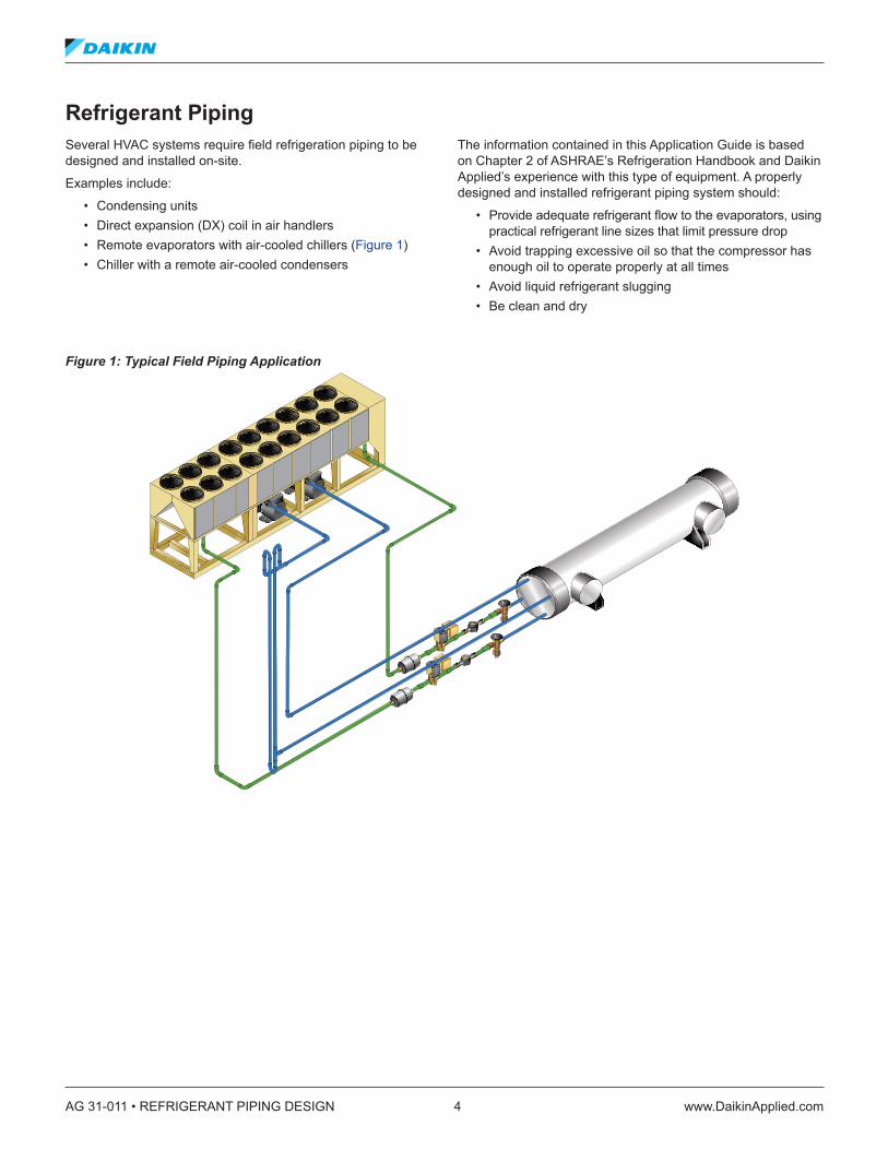
Refrigerant PipingSeveral HVAC systems require field refrigeration piping to be designed and installed on-site.
Examples include:
• Condensing units • Direct expansion (DX) coil in air handlers • Remote evaporators with air-cooled chillers (Figure 1) • Chiller with a remote air-cooled condensers
The information contained in this Application Guide is based on Chapter 2 of ASHRAE’s Refrigeration Handbook and Daikin Applied’s experience with this type of equipment. A properly designed and installed refrigerant piping system should:
• Provide adequate refrigerant flow to the evaporators, using practical refrigerant line sizes that limit pressure drop
• Avoid trapping excessive oil so that the compressor has enough oil to operate properly at all times
• Avoid liquid refrigerant slugging • Be clean and dry
Figure 1: Typical Field Piping Application

www.DaikinApplied.com 5 AG 31-011 • REFRIGERANT PIPING DESIGN
Refrigerant Piping Design Check ListThe first step in refrigerant piping design is to gather product and jobsite information. A checklist for each is provided below. How this information is used will be explained throughout the rest of this guide.
Product Information• Model number of unit components (condensing section,
evaporator, etc.) • Maximum capacity per refrigeration circuit • Minimum capacity per refrigeration circuit • Unit operating charge • Unit pump down capacity• Refrigerant type • Unit options (Hot Gas Bypass, etc.) • Does equipment include isolation valves and charging ports• Does the unit have pump down?
Jobsite Information• Sketch of how piping will be run, including:
— Distances — Elevation changes — Equipment layout — Fittings — Specific details for evaporator piping connections
• Ambient conditions where piping will be run• Ambient operating range (will the system operate during
the winter?)• Type of cooling load (comfort or process) • Unit isolation (spring isolators, rubber-in-shear, etc.)
Tip: Use this list to gather the information required to design your refrigerant piping system
AG 31-011 • REFRIGERANT PIPING DESIGN 6 www.DaikinApplied.com
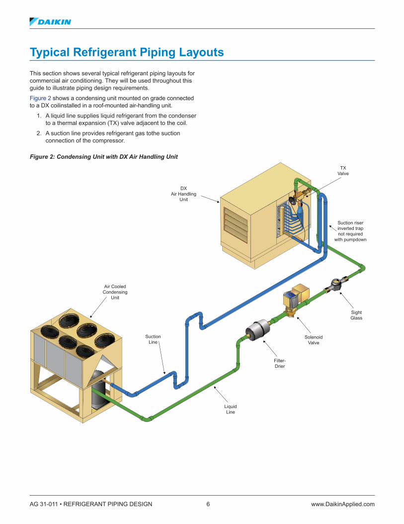
Typical Refrigerant Piping LayoutsThis section shows several typical refrigerant piping layouts for commercial air conditioning. They will be used throughout this guide to illustrate piping design requirements.
Figure 2 shows a condensing unit mounted on grade connected to a DX coilinstalled in a roof-mounted air-handling unit.
1. A liquid line supplies liquid refrigerant from the condenser to a thermal expansion (TX) valve adjacent to the coil.
2. A suction line provides refrigerant gas tothe suction connection of the compressor.
Figure 2: Condensing Unit with DX Air Handling Unit
DXAir Handling
Unit
TXValve
SightGlass
SolenoidValve
Filter-Drier
LiquidLine
SuctionLine
Air CooledCondensing
Unit
Suction riserinverted trapnot required
with pumpdown

www.DaikinApplied.com 7 AG 31-011 • REFRIGERANT PIPING DESIGN
Figure 3 shows a roof-mounted air-cooled chiller with a remote evaporator inside the building.
1. There are two refrigeration circuits, each with a liquid line supplying liquid refrigerant from the condenser to a TX valve adjacent to the evaporator, and a suction line returning refrigerant gas from the evaporator to the suction connections of the compressor.
2. There is a double suction riser on one of the circuits. Double suction risers are covered inmore detail in the “Oil Return in Suction and Discharge Risers” on page 21.
Figure 3: Air-Cooled Chiller with Remote Evaporator
RemoteEvaporator
Air CooledChiller with
RemoteEvaporator
SightGlass
TXValve
SolenoidValve
Filter-Drier
LiquidLine
LiquidLineRiser
Suction LineRiser
DoubleSuction
LineRiser

AG 31-011 • REFRIGERANT PIPING DESIGN 8 www.DaikinApplied.com
Figure 4 shows an indoor chiller with a remote air-cooled condenser on the roof.
1. The discharge gas line runs from the discharge side of the compressor to the inlet of the condenser.
2. The liquid line connects the outlet of the condenser to a TX valve at the evaporator.
3. The hot gas bypass line on the circuit runs from the discharge line of the compressor to the liquid line connection at the evaporator.
Figure 4: Indoor Chiller with Remote Air-cooled Condenser Air CooledCondenser
Discharge lineinverted trap
(can be replacedwith a check valve)
DischargeLine
LiquidLineRiser
Dischargeriser trap
only at base
Hot gas bypasstop connection
to avoid refrigerantcollection
SightGlass
TXValve
SolenoidValve
Filter-Drier
Chiller

www.DaikinApplied.com 9 AG 31-011 • REFRIGERANT PIPING DESIGN
Piping Design BasicsGood piping design results in a balance between the initial cost, pressure drop, and system reliability. The initial cost is impacted by the diameter and layout of the piping.The pressure drop in the piping must be minimized to avoid adversely affecting performance and capacity. Because almost all field-piped systems have compressor oil passing through the refrigeration circuit and back to the compressor, a minimum velocity must be maintained in the piping so that sufficient oil is returned to the compressor sump at full and part load conditions. A good rule of thumb is a minimum of:
• 500 feet per minute (fpm) or 2.54 meters per second (mps) for horizontal suction and hot gas lines
• 1000 fpm (5.08 mps) for suction and hot gas risers • Less than 300 fpm (1.54 mps) to avoid liquid hammering
from occurring when the solenoid closes on liquid lines
Hard drawn copper tubing is used for halocarbon refrigeration systems. Types L and K are approved for air conditioning and refrigeration (ACR) applications. Type M is not used because the wall is too thin. The nominal size is based on the outside diameter (OD). Typical sizes include 5/8 inch, 7/8 inch, 1-1/8 inch, etc.
Figure 5: Refrigerant Grade Copper Tubing
Copper tubing intended for ACR applications is dehydrated, charged with nitrogen, and plugged by the manufacturer (see Figure 5).
Formed fittings, such as elbows and tees, are used with the hard drawn copper tubing. All joints are brazed with oxy-acetylene torches by a qualified technician.
As mentioned before, refrigerant line sizes are selected to balance pressure drop with initial cost, in this case of the copper tubing while also maintaining enough refrigerant velocity to carry oil back to the compressor.
Pressure drops are calculated by adding the length of tubing required to the equivalent feet (meters) of all fittings in the line. This is then converted to PSI (kPa).
Pressure Drop and Temperature Change As refrigerant flows through pipes the pressure drops and changes the refrigerant saturation temperature. Decreases in both pressure and saturation temperature adversely affect compressor performance. Proper refrigeration system design attempts to minimize this change to less than 2°F (1.1°C) per line. Therefore, it is common to hear pressure drop referred to as “2°F” versus PSI (kPa) when matching refrigeration system components. For example, a condensing unit may produce 25 tons (87.9 kW) of cooling at 45°F (7.2°C) saturated suction temperature. Assuming a 2°F (1.1°C) line loss, the evaporator would have to be sized to deliver 25 tons (87.9 kW) cooling at 47°F (7.2°C) saturated suction temperature.
Table 1 compares pressure drops in temperatures and pressures for several common refrigerants. Note that the refrigerants have different pressure drops for the same change in temperature. For example, many documents refer to acceptable pressure drop being 2°F (1.1°C) or about 3 PSI (20.7 kPa) for R-22. The same 3 PSI change in R-410A, results in a 1.2°F (0.7°C) change in temperature.
Table 1: Temperature versus Pressure Drop
RefrigerantSuction Pressure Drop Discharge Pressure Drop Liquid Pressure Drop
°F (°C) PSI (kPa) °F (°C) PSI (kPa °F (°C) PSI (kPa) R-22 2 (1.1) 2.91 (20.1) 1 (0.56) 3.05 (21.0) 1 (0.56) 3.05 (21.0)
R-407C 2 (1.1) 2.92 (20.1) 1 (0.56) 3.3 (22.8) 1 (0.56) 3.5 (24.1) R-410A 2 (1.1) 4.5 (31.0) 1 (0.56) 4.75 (32.8) 1 (0.56) 4.75 (32.8) R-134a 2 (1.1) 1.93 (13.3) 1 (0.56) 2.2 (15.2) 1 (0.56) 2.2 (15.2)
NOTE: Suction and discharge pressure drops based on 100 equivalent feet (30.5 m) and 40°F (4.4°C) saturated temperature.
AG 31-011 • REFRIGERANT PIPING DESIGN 10 www.DaikinApplied.com
Liquid LinesLiquid lines connect the condenser to the evaporator and carry liquid refrigerant to the TX valve. If the refrigerant in the liquid line flashes to a gas because the pressure drops too low or because of an increase in elevation, then the refrigeration system will operate poorly. Liquid sub-cooling is the only method that prevents refrigerant flashing to gas due to pressure drops in the line.
The actual line size should provide no more than a 2 to 3°F (1.1 to 1.7°C) pressure drop. The actual pressure drop in PSI (kPa) will depend on the refrigerant.
Oversizing liquid lines is discouraged because it will significantly increase the system refrigerant charge. This, in turn, affects the oil charge.
Figure 2 on page 6 shows the condenser below the evaporator. As the liquid refrigerant is lifted from the condenser to the evaporator, the refrigerant pressure is lowered. Different refrigerants will have different pressure changes based on elevation. Refer Table 2 to for specific refrigerants. The total pressure drop in the liquid line is the sum of the friction loss, plus the weight of the liquid refrigerant column in the riser.
Table 2: Pressure Drop in Liquid Lines by RefrigerantRefrigerant Pressure Drop PSI/ft (kPa/m) Riser
R-22 0.5 (11.31)R-407C 0.47 (10.63)R-410A 0.43 (9.73)R-134a 0.5 (11.31)
Based on saturated liquid refrigerant at 100°F (37.7°C)
Only sub-cooled liquid refrigerant will avoid flashing at the TX valve in this situation.If the condenser had been installed above the evaporator, the pressure increase from the weight of the liquid refrigerant in the line would have prevented the refrigerant from flashing in a properly sized line without sub-cooling.
It is important to have some sub-cooling at the TX valve so that the valve will operate properly and not fail prematurely. Follow the manufacturer’s recommendations. If none are available, then provide 4 to 6°F (2.2 to 3.3°C) of sub-cooling at the TX valve.
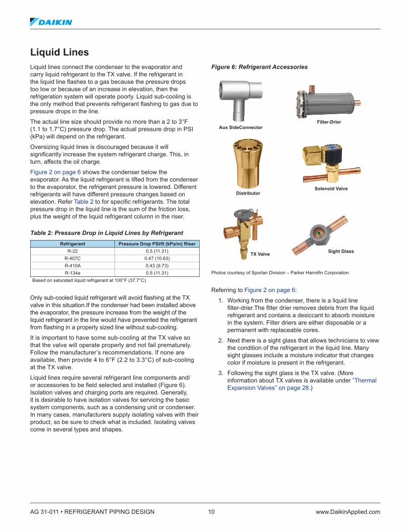
Liquid lines require several refrigerant line components and/or accessories to be field selected and installed (Figure 6). Isolation valves and charging ports are required. Generally, it is desirable to have isolation valves for servicing the basic system components, such as a condensing unit or condenser. In many cases, manufacturers supply isolating valves with their product, so be sure to check what is included. Isolating valves come in several types and shapes.
Figure 6: Refrigerant Accessories
Photos courtesy of Sporlan Division – Parker Hannifin Corporation
Referring to Figure 2 on page 6:
1. Working from the condenser, there is a liquid line filter-drier.The filter drier removes debris from the liquid refrigerant and contains a desiccant to absorb moisture in the system. Filter driers are either disposable or a permanent with replaceable cores.
2. Next there is a sight glass that allows technicians to view the condition of the refrigerant in the liquid line. Many sight glasses include a moisture indicator that changes color if moisture is present in the refrigerant.
3. Following the sight glass is the TX valve. (More information about TX valves is available under ”Thermal Expansion Valves” on page 28.)
Aux SideConnector
Distributor
Sight Glass
Solenoid Valve
TX Valve
Filter-Drier
www.DaikinApplied.com 11 AG 31-011 • REFRIGERANT PIPING DESIGN
Possible accessories for this system include:
• A hot gas bypass port. This is a specialty fitting that integrates with the distributor – an auxiliary side connector (ASC).
• A pump down solenoid valve. If a pump down is utilized, the solenoid valve will be located just before the TX valve, as close to the evaporator as possible.
• Receivers in the liquid line. These are used to store excess refrigerant for either pump down or service (if the condenser has inadequate volume to hold the system charge), or as part of a flooded low ambient control approach (More information about flooded low ambient control approach is available under “Condenser Flood Back Design” on page 34). Receivers are usually avoided because they remove sub-cooling from the condenser, increase the initial cost, and increase the refrigerant charge.
Liquid lines should be sloped 1/8 inch per foot (10.4 mm/m) in the direction of refrigerant flow. Trapping is unnecessary.
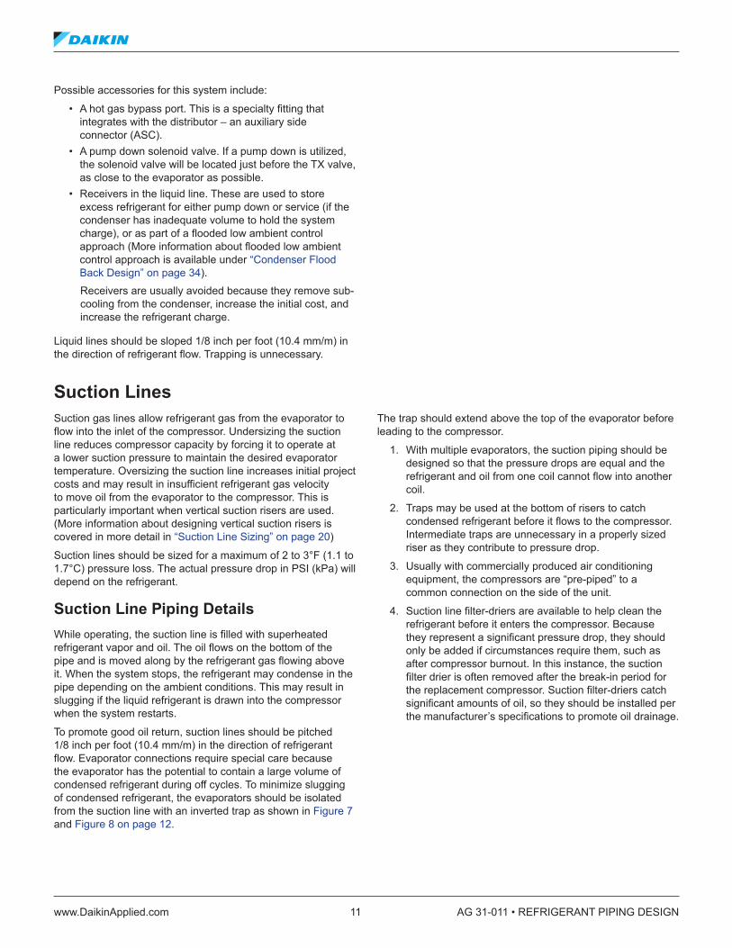
Suction LinesSuction gas lines allow refrigerant gas from the evaporator to flow into the inlet of the compressor. Undersizing the suction line reduces compressor capacity by forcing it to operate at a lower suction pressure to maintain the desired evaporator temperature. Oversizing the suction line increases initial project costs and may result in insufficient refrigerant gas velocity to move oil from the evaporator to the compressor. This is particularly important when vertical suction risers are used. (More information about designing vertical suction risers is covered in more detail in “Suction Line Sizing” on page 20)
Suction lines should be sized for a maximum of 2 to 3°F (1.1 to 1.7°C) pressure loss. The actual pressure drop in PSI (kPa) will depend on the refrigerant.
Suction Line Piping DetailsWhile operating, the suction line is filled with superheated refrigerant vapor and oil. The oil flows on the bottom of the pipe and is moved along by the refrigerant gas flowing above it. When the system stops, the refrigerant may condense in the pipe depending on the ambient conditions. This may result in slugging if the liquid refrigerant is drawn into the compressor when the system restarts.
To promote good oil return, suction lines should be pitched 1/8 inch per foot (10.4 mm/m) in the direction of refrigerant flow. Evaporator connections require special care because the evaporator has the potential to contain a large volume of condensed refrigerant during off cycles. To minimize slugging of condensed refrigerant, the evaporators should be isolated from the suction line with an inverted trap as shown in Figure 7 and Figure 8 on page 12.
The trap should extend above the top of the evaporator before leading to the compressor.
1. With multiple evaporators, the suction piping should be designed so that the pressure drops are equal and the refrigerant and oil from one coil cannot flow into another coil.
2. Traps may be used at the bottom of risers to catch condensed refrigerant before it flows to the compressor. Intermediate traps are unnecessary in a properly sized riser as they contribute to pressure drop.
3. Usually with commercially produced air conditioning equipment, the compressors are “pre-piped” to a common connection on the side of the unit.
4. Suction line filter-driers are available to help clean the refrigerant before it enters the compressor. Because they represent a significant pressure drop, they should only be added if circumstances require them, such as after compressor burnout. In this instance, the suction filter drier is often removed after the break-in period for the replacement compressor. Suction filter-driers catch significant amounts of oil, so they should be installed per the manufacturer’s specifications to promote oil drainage.
AG 31-011 • REFRIGERANT PIPING DESIGN 12 www.DaikinApplied.com
Figure 7: Remote Evaporator Piping Detail
Figure 8: Suction Piping Details
Inverted traponly required if
there areevaporatorsupstream
Trap to protectTX valve
from liquid line
Slope indirection of therefrigerant flow
Slope indirection of
refrigerant flow
Trap to protectTX valve bulb
from liquidrefrigerant
Compressor Above Coil
Slope indirection of
refrigerant flow
Trap abovecoil height notrequired withpumpdown
systems
Compressor Below Coil
Slope indirection of
refrigerant flow
No inverted traprequired if
properly sloped
Trap to protectTX valve bulb
from liquidrefrigerant
Compressor Above Coil
www.DaikinApplied.com 13 AG 31-011 • REFRIGERANT PIPING DESIGN
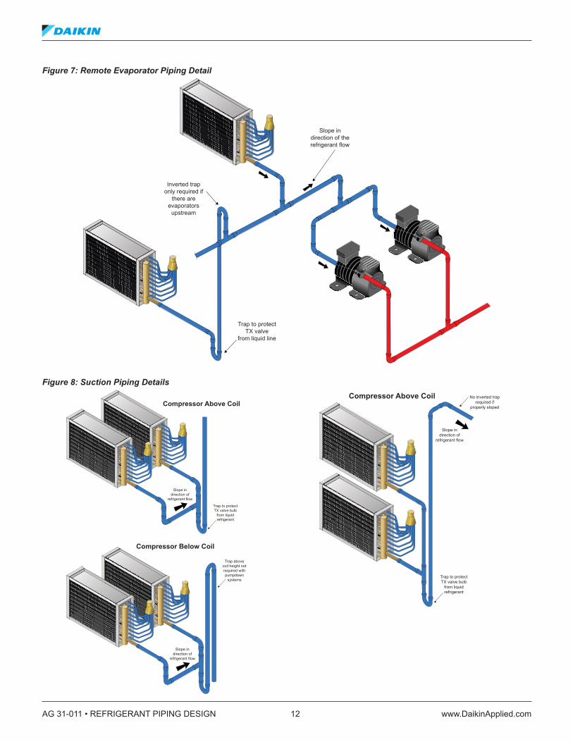
Discharge LinesDischarge gas lines (often referred to as hot gas lines) allow refrigerant to flow from the discharge of the compressor to the inlet of the condenser. Undersizing discharge lines will reduce compressor capacity and increase compressor work. Over sizing discharge lines increases the initial cost of the project and may result in insufficient refrigerant gas velocity to carry oil back to the compressor.
Discharge lines should be sized for no more than 2 to 3°F (1.1 to 1.7°C) pressure loss. The actual pressure drop in PSI will depend upon the refrigerant. Figure 9 illustrates how capacity and power consumption are affected by increasing pressure drop for both discharge and suction lines. Although these curves are based on an R-22 system, similar affects occur with other refrigerants.
Figure 9: Capacity and Performances versus Pressure Drop Approx. Effect of Gas Line Pressure Drops on R-22 Compressor Capacity & Power – Suction Line
Approx. Effect of Gas Line Pressure Drops on R-22 Compressor Capacity & Power – Discharge Line
Approx. Effect of Gas Line Pressure Drops on R-22 Compressor Capacity & Power – Suction Line
92
94
96
98
100
102
104
106
108
110
0 0.5 1 1.5 2 2.5 3 3.5 4
Line Loss, oF
%
Power
Capacity
Approx. Effect of Gas Line Pressure Drops on R-22 Compressor Capacity & Power – Discharge Line
96
98
100
102
104
106
108
0 0.5 1 1.5 2 2.5 3 3.5 4
Line Loss, oF
%
Power
Capacity

AG 31-011 • REFRIGERANT PIPING DESIGN 14 www.DaikinApplied.com
Discharge Line Piping DetailsDischarge lines carry both refrigerant vapor and oil. Since refrigerant may condense during the OFF cycle, the piping should be designed to avoid liquid refrigerant and oil from flowing back into the compressor. Traps can be added to the bottom of risers to catch oil and condensed refrigerant during OFF cycles, before it flows backward into the compressor. Intermediate traps in the risers are unnecessary in a properly sized riser as they increase the pressure drop. Discharge lines should be pitched 1/8 inch per foot (10.4 mm/m) in the direction of refrigerant flow towards the condenser (Figure 10).
Whenever a condenser is located above the compressor, an inverted trap or check valve should be installed at the condenser inlet to prevent liquid refrigerant from flowing backwards into the compressor during OFF cycles. In some cases (i.e. with reciprocating compressors), a discharge muffler is installed in the discharge line to minimize pulsations (that cause vibration). Oil is easily trapped in a discharge muffler, so it should be placed in the horizontal or downflow portion of the piping, as close to the compressor as possible.
Figure 10: Discharge Line Piping Details
Slope indirection of
refrigerant flow
Keep trap at bottom of riser
as small as possible
www.DaikinApplied.com 15 AG 31-011 • REFRIGERANT PIPING DESIGN
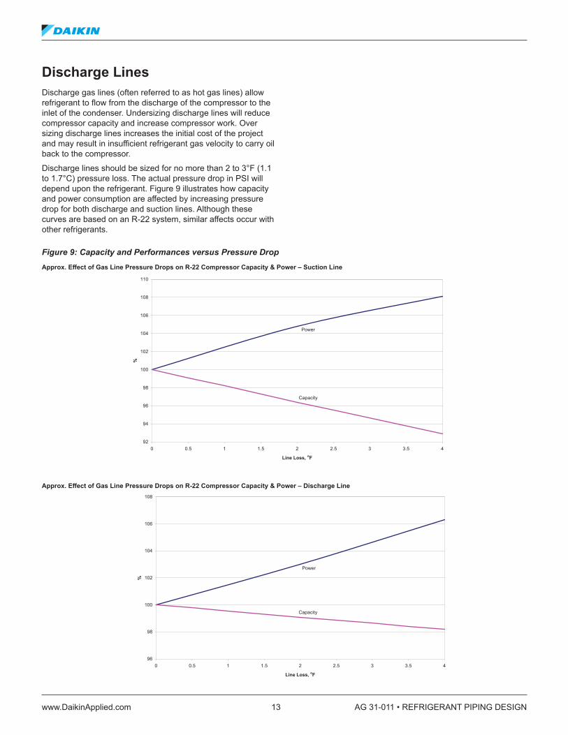
Multiple Refrigeration CircuitsFor control and redundancy, many refrigeration systems include two or more refrigeration circuits. Each circuit must be kept separate and designed as if it were a single system. In some cases, a single refrigeration circuit serves multiple evaporators, but multiple refrigeration circuits should never be connected to a single evaporator. A common mistake is to install a two circuit condensing units with a single circuit evaporator coil.
Figure 11 shows common DX coils that include multiple circuits. Interlaced is the most common. It is possible to have individual coils, each with a single circuit, installed in the same system and connected to a dedicated refrigeration circuit.
While most common air conditioning applications have one evaporator for each circuit, it is possible to connect multiple evaporators to a single refrigeration circuit.
Figure 12 shows a single refrigeration circuit serving two DX coils. Note that each coil has its own solenoid and thermal expansion valve. There should be one TX valve for each distributor. Individual solenoids should be used if the evaporators will be operated independently (i.e. for capacity control). If both evaporators will operate at the same time, then a single solenoid valve in a common pipe may be used.
If the two evaporators serve a common airstream, then one solenoid valve serving both evaporators is sufficiant at point “X” in Figure 12.
Figure 11: DX Coils with Multiple Circuits
Figure 12: Two Evaporators on a Common Refrigeration Circuit
Refrigerant(In)
Refrigerant(In)
Refrigerant(In)
Refrigerant(Out)
Face Control Row Control Interlaced
Refrigerant(Out)
Refrigerant(Out)
TX Valve
Solenoid Valve
Filter-Drier
SightGlass
SuctionLine
LiquidLine
ExternalEqualization
Line
Bulb mountedon horizontal pipe,
close to coil toavoid mounting
in traps
Slope in directionof refrigerant flow
Trap to protectTX Valve bulb
from liquidrefrigerant
X

AG 31-011 • REFRIGERANT PIPING DESIGN 16 www.DaikinApplied.com
Sizing Refrigerant Lines
Refrigerant Capacity TablesAppendix 2 (page 40) and Appendix 3 (page 59) provide refrigerant line sizes for commonly used refrigerants. There is data for suction, discharge, and liquid lines. Suction and discharge lines have data for 0.5, 1, and 2°F (0.28, 0.56, and 1.7°C) changes in saturated suction temperature (SST). Liquid lines are based on 1°F (0.56°C) changes in saturation temperature.
The data is based on 105°F (40.6°C) condensing temperature (common for water-cooled equipment) and must be corrected for other condensing temperatures (air-cooled equipment is typically 120 to 125°F [48.9 to 51.7°C]). The tables are also based on 100 feet (30.5 m) of equivalent length. The actual pressure drop is estimated based on the actual equivalent length of the application using equations in the footnotes of the refrigerant capacity tables.
Tip: Saturated suction temperature is based upon the pressure leaving the evaporator and represents the refrigerant temperature as a gas without superheat. The actual refrigerant temperature leaving the evaporator will be higher than this. The difference between the two temperatures is called superheat.
www.DaikinApplied.com 17 AG 31-011 • REFRIGERANT PIPING DESIGN
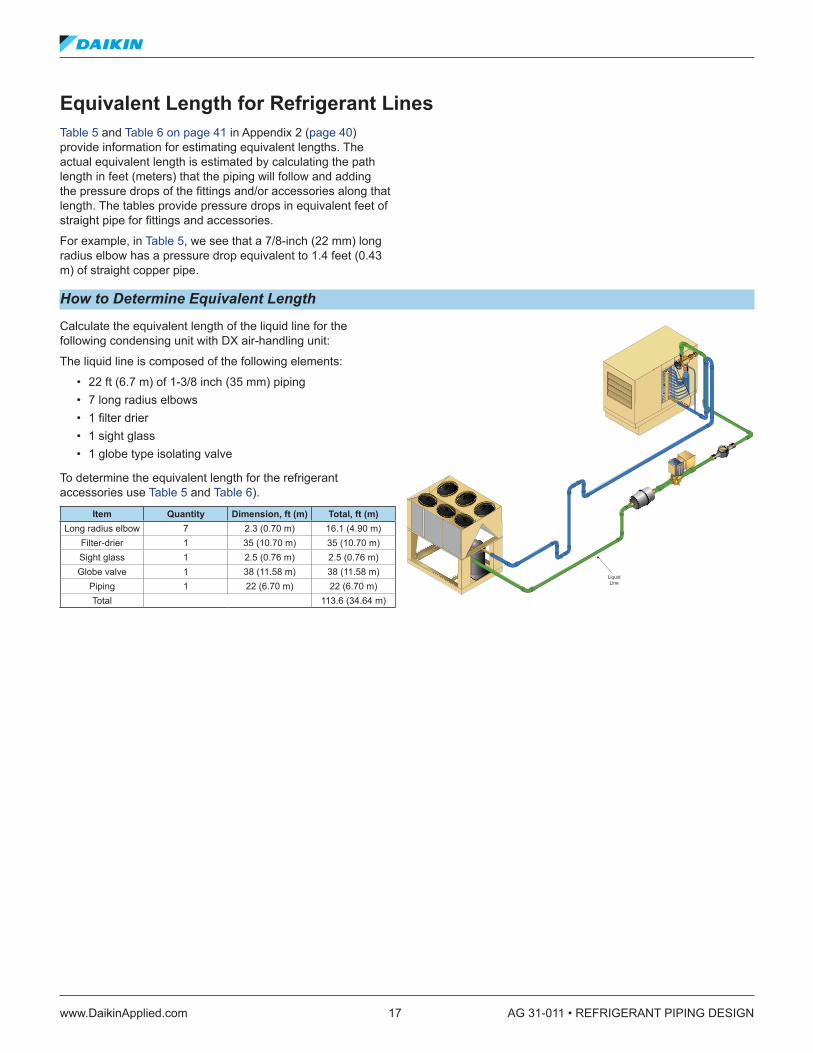
Equivalent Length for Refrigerant LinesTable 5 and Table 6 on page 41 in Appendix 2 (page 40) provide information for estimating equivalent lengths. The actual equivalent length is estimated by calculating the path length in feet (meters) that the piping will follow and adding the pressure drops of the fittings and/or accessories along that length. The tables provide pressure drops in equivalent feet of straight pipe for fittings and accessories.
For example, in Table 5, we see that a 7/8-inch (22 mm) long radius elbow has a pressure drop equivalent to 1.4 feet (0.43 m) of straight copper pipe.
How to Determine Equivalent Length
Calculate the equivalent length of the liquid line for the following condensing unit with DX air-handling unit:
The liquid line is composed of the following elements:
• 22 ft (6.7 m) of 1-3/8 inch (35 mm) piping • 7 long radius elbows • 1 filter drier • 1 sight glass • 1 globe type isolating valve
To determine the equivalent length for the refrigerant accessories use Table 5 and Table 6).
Item Quantity Dimension, ft (m) Total, ft (m) Long radius elbow 7 2.3 (0.70 m) 16.1 (4.90 m)
Filter-drier 1 35 (10.70 m) 35 (10.70 m) Sight glass 1 2.5 (0.76 m) 2.5 (0.76 m) Globe valve 1 38 (11.58 m) 38 (11.58 m)
Piping 1 22 (6.70 m) 22 (6.70 m) Total 113.6 (34.64 m)
LiquidLine

AG 31-011 • REFRIGERANT PIPING DESIGN 18 www.DaikinApplied.com
How to Size Liquid Lines
Size the refrigerant liquid lines and determine the sub-cooling required to avoid flashing at the TX valve for the condensing unit with DX air-handling unit shown in the previous example.
The system:
• Uses R-410A • Has copper pipes • Evaporator operates at 40°F (4.4°C) • Condenser operates at 120°F (48.9°C) • Capacity is 60 tons (211 kW) • Liquid line equivalent is 113.6 ft (34.64 m) • Has a 20 ft (6.1 m) riser with the evaporator above the
condenser
Step 1 – Estimate Pipe Size
To determine the liquid line pipe size for a 60 ton unit, use Table 9 in Appendix 2. According to the table, a 1-3/8 inch (35 mm) pipe will work for a 79.7 ton (280 kW) unit. Note, the table conditions (equivalent length and condensing temperature) are different than the design conditions.
Step 2 – Calculate Actual ∆T
Using Note #5 in the table, we can calculate the saturation temperature difference based upon the design conditions:
Step 3 – Calculate Actual Piping Pressure Drop
According to Table 9, the pressure drop for 1°F (0.56°C) saturation temperature drop with a 100 ft equivalent length is 4.75 PSI (32.75 kPa).
The actual piping pressure drop is determined using the equation:
Step 4 – Calculate Total Pressure Drop
Next to determine the Total pressure drop, we use Table 2 on page 10, and recall that the riser is 20 ft. For R-410A the pressure drop is 0.43 PSI per ft (9.73 kPa/m).
Total Pressure Drop = Actual Pressure Drop + Riser Pressure DropTotal Pressure Drop = 3.23 PSI + 8.6 PSI = 11.83 PSI(Total Pressure Drop = 59.35 kPa + 22.81 kPa = 82.16 kPa
Step 5 – Determine the Saturated Pressure of R-410A at the TX Valve
Using refrigerant property tables which can be found in Appendix 2 of Daikin Applied’s Refrigerant Application Guide (AG 31-007, see www.DaikinApplied.com) the saturated pressure for R-410A at 120°F is 433 PSIA (absolute) (2985 kPaA). To calculate the saturation pressure at the TX valve, we take the saturated pressure of R-410A at 120°F and subtract the total pressure drop.
Saturated PressureTX Valve = Saturated Pressure120°F – Total Pressure Drop
Saturated PressureTX Valve = 433.0 PSIA – 11.83 PSIA = 421.17 PSIA(Saturated PressureTX Valve = 2985.0 kPa – 82.15 lPa = 2902.85 kPa)
Step 6 – Determine the Saturation Temperature at the TX Valve
Referring back to the Refrigeration property tables in Application Guide 31-007, the saturation temperature at the TX valve can be interpolated using the saturation pressure at the TX valve (421 PSIA). The saturation temperature at the TX valve is found to be 117.8°F
∆TActual = ∆TTableActual LengthTable Length
Actual CapacityTable Capacity
1.8
∆TActual = 1°F
∆TActual = 0.56°C
= 0.68°F113.6 ft100.0 ft
60.0 Tons79.7 Tons
1.8
= 0.39°C34.64 m30.48 m
211 kW280 kW
1.8
Liquid Line — Step 2
Pressure DropActual = Pressure DropTable
∆TActual
∆TTable
Pressure DropActual = 4.75 PSI
Pressure DropActual = 32.75 kPa
= 3.23 PSI0.68°F1°F
= 22.81 kPa0.39°C0.56°C
Liquid Line — Step 3
Pressure Drop from the Riser = Pressure Drop ×
Total Pressure Drop = Actual Pressure Drop + Riser Pressure Drop
Total Pressure Drop = 3.23 PSI + 8.6 PSI = 11.83 PSI
(Total Pressure Drop = 59.35 kPa + 22.81 kPa = 82.16 kPa)
Saturated PressureTX Valve = Saturated Pressure120°F – Total Pressure Drop
Saturated PressureTX Valve = 433.0 PSIA + 11.83 PSIA = 421.17 PSIA
(Saturated PressureTX Valve = 2985.0 kPa + 82.15 kPa = 2902.85 kPa)
Refrigerant Pressure Dropft
Pressure Drop from the Riser = 20.0 ft ×
Pressure Drop from the Riser = 6.1 m ×
= 8.6 PSI0.43 PSIft
= 259.35 kPa9.73 kPam
Liquid Line — Step 4
Liquid Line — Step 5
Subcooling = Actual Saturation Temperature – Saturation TemperatureTX Valve
Subcooling = 120.0°F – 117.8°F = 2.2°F
Liquid Line — Step 7
Subcooling Requirement = TX Valve Temperature + Minimum System Temperature
Subcooling Requirement = 2.2°F + 4.0°F = 6.2°F
Liquid Line — Step 8
www.DaikinApplied.com 19 AG 31-011 • REFRIGERANT PIPING DESIGN
How to Size Liquid Lines (continued)
Step 7- Determine The Sub-cooling Required for Saturated Liquid at the TX Valve
The sub-cooling require to have saturated liquid at the TX valve can be found by:
Subcooling = Actual Saturation Temperature – Saturation TemperatureTX Valve
Subcooling = 120.0°F – 117.8°F = 2.2°F
Step 8- Determine the Required Sub-cooling for Proper Operation
2.2°F is the amount of sub-cooling required to have saturated liquid refrigerant at the TX valve. Anything less, and the refrigerant will start to flash and the TX valve will not operate properly. For TX valves to operate properly and avoid diaphragm fluttering, there should be an additional 4°F of sub-cooling at the TX Valve.
Subcooling Requirement = TX Valve Temperature + Minimum System Temperature
Subcooling Requirement = 2.2°F + 4.0°F = 6.2°F

AG 31-011 • REFRIGERANT PIPING DESIGN 20 www.DaikinApplied.com
Refrigerant OilIn the DX refrigeration systems covered by this guide, some amount of compressor lubricating oil travels with the refrigerant throughout the piping system. The system design must promote oil return or the compressor sump will run dry and damage the compressor.
Recall, refrigerant piping should be pitched to promote adequate oil return. Fittings and piping layout that traps and retains oil must be avoided. Compressor capacity reduction contributes to the challenge of designing the system.
For example, a screw compressor may reduce refrigerant flow (unload) down to 25%. At this reduced refrigerant flow rate, the refrigerant velocity is reduced to the point that the oil may not be pushed through the piping system and back to the compressor.
Examples of compressors that unload include:
• Scroll compressors often have multiple compressors on a common refrigeration circuit. The circuit can unload to the smallest compressor size. For example, 4 equally sized compressors can unload down to 25%.
• Individual reciprocating compressors unload down to as low as 33%. There can be multiple compressors on a common circuit allowing even more unloading.
• Screw compressors may unload down to 25%.
Always check the manufacturer’s information to determine circuit unloading.
More piping typically requires more oil. This is particularly true for long liquid lines. Residential split systems are often pre-charged at the factory with enough oil and refrigerant for a specified line distance. When that distance is exceeded, additional refrigerant and oil will be required. For commercial split systems, the equipment may come pre-charged or it may be provided with either nitrogen or a small holding charge. The refrigerant and oil charge is then provided in the field.
To confirm if more oil is required, the system refrigerant charge must be calculated. Table 19 on page 50 through Table 22 on page 50 provide the charge per 100 feet(30.5 m) length for various refrigerants. Generally, the oil charge should be 2 to 3% of the liquid line charge. Consult the manufacturer for the correct volume of oil in the system and the amount of oil shipped in the compressor sump. The required oil that needs to be added is the calculated total oil requirement less the oil shipped in the equipment.
Required oil = Total oil required – oil shipped in equipmentHFC refrigerants use synthetic POE oils. These oils cannot be mixed with mineral oils. Refer to the manufacturer’s instructions for the correct type of oil to use.
Suction Line SizingSuction lines contain gaseous refrigerant that moves oil along the piping and back tothe compressor. Over-sizing suction pipes increases the initial costs and may reduce the refrigerant gas velocity to the point where oil is not returned to the compressor. Recall, under-sizing suction pipes reduces system capacity. Oil movement is also impacted negatively by risers, because gravity prevents oil from returning to the compressor.

www.DaikinApplied.com 21 AG 31-011 • REFRIGERANT PIPING DESIGN
Oil Return in Suction and Discharge RisersTable 10 on page 45 through Table 18 on page 49 show minimum capacity oil return for suction and discharge risers. When unloading capability exists, risers should be checked to verify that the minimum capacity allows for acceptable oil return. For air conditioning applications that contain less than 100 feet (30.5 m) of piping and no more than 33% capacity reduction per circuit, a properly sized riser should be found. It may be necessary to use a smaller pipe diameter for the riser, which creates a higher than desired pressure drop at full capacity, for optimal oil movement. To compensate, a larger diameter pipe may be used for horizontal runs to minimize the total pressure drop.
Figure 13 shows the traditional method for reducing the pipe diameter for suction and discharge risers. This approach will prevent oil from being trapped in the horizontal portion of the pipe.
Figure 14 shows a preferred method for RCS Condensing Units. It replaces 90° elbows at “X” and “Y” with 45° elbows to minimize the oil collection in the trap and replaces the vertical reducer “Z” with an eccentric horizontal reducer.
Figure 13: Traditional Reduction Fittings for Risers
Figure 14: Preferred Reduction Fittings for Risers
Install expanderin horizontal pipe
Install reducerin vertical pipe
XZ
Y
Install expanderin horizontal pipe
Install reducerin horizontal pipeX Z
Y
45°

AG 31-011 • REFRIGERANT PIPING DESIGN 22 www.DaikinApplied.com
Figure 15: Double Suction Riser Detail Figure 15 shows a double suction riser arrangement that is more common in refrigeration applications where suction pressure drops are more critical. Most modern air conditioning applications can be met without requiring a double suction riser. Although the operation and design of a double suction riser is included in this guide, it is strongly recommended that systems be designed without a double suction riser, even if the pressure drop in the suction or discharge line is higher than desired.
In a double suction riser at full capacity, the refrigerant flow passes through both risers with enough velocity to move the oil. At minimum capacity, oil in the riser flows backward and fills the trap at the bottom. Once the trap is full of oil, refrigerant flow through the large diameter riser is cut off and only refrigerant gas flows through the smaller diameter riser. The sum of the two risers is sized for full capacity. The smaller diameter riser is sized for minimum capacity.
One of the challenges of double suction risers is that they hold a significant amount of oil within the trap. Refrigeration compressors often have larger sumps than commercial compressors, so the oil lost to the trap is less problematic for refrigeration than commercial compressors. In addition, when the capacity increases in a double suction riser, a large amount of oil is “blown” through the piping system back to the compressor. Either an oil separator or a suction accumulator (both common in refrigeration systems) may be required for a double suction riser to operate properly without causing damage to the compressor.
Tip: For most air conditioning applications, a single pipe riser will work. In this case, it may be necessary to undersize the riser pipe by one pipe size to provide better oil management.
Slope indirection of
refrigerant flow
Small diameter pipe inverted trap not required if pipe isproperly sloped
MinimizeTrap
Volume
LargeDiameter
Riser
SmallDiameter
Riser
www.DaikinApplied.com 23 AG 31-011 • REFRIGERANT PIPING DESIGN
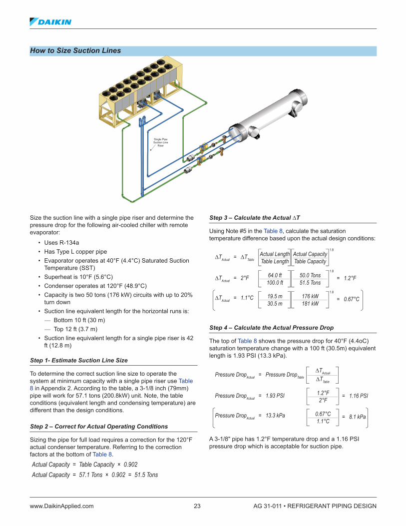
How to Size Suction Lines
Size the suction line with a single pipe riser and determine the pressure drop for the following air-cooled chiller with remote evaporator:
• Uses R-134a • Has Type L copper pipe • Evaporator operates at 40°F (4.4°C) Saturated Suction
Temperature (SST) • Superheat is 10°F (5.6°C) • Condenser operates at 120°F (48.9°C) • Capacity is two 50 tons (176 kW) circuits with up to 20%
turn down • Suction line equivalent length for the horizontal runs is:
— Bottom 10 ft (30 m) — Top 12 ft (3.7 m)
• Suction line equivalent length for a single pipe riser is 42 ft (12.8 m)
Step 1- Estimate Suction Line Size
To determine the correct suction line size to operate the system at minimum capacity with a single pipe riser use Table 8 in Appendix 2. According to the table, a 3-1/8 inch (79mm) pipe will work for 57.1 tons (200.8kW) unit. Note, the table conditions (equivalent length and condensing temperature) are different than the design conditions.
Step 2 – Correct for Actual Operating Conditions
Sizing the pipe for full load requires a correction for the 120°F actual condenser temperature. Referring to the correction factors at the bottom of Table 8.
Actual Capacity = Table Capacity × 0.902Actual Capacity = 57.1 Tons × 0.902 = 51.5 Tons
Step 3 – Calculate the Actual ∆T
Using Note #5 in the Table 8, calculate the saturation temperature difference based upon the actual design conditions:
Step 4 – Calculate the Actual Pressure Drop
The top of Table 8 shows the pressure drop for 40°F (4.4oC) saturation temperature change with a 100 ft (30.5m) equivalent length is 1.93 PSI (13.3 kPa).
A 3-1/8" pipe has 1.2°F temperature drop and a 1.16 PSI pressure drop which is acceptable for suction pipe.
Single PipeSuction Line
Riser
∆TActual = ∆TTableActual LengthTable Length
Actual CapacityTable Capacity
1.8
∆TActual = 2°F
∆TActual = 1.1°C
= 1.2°F64.0 ft100.0 ft
50.0 Tons51.5 Tons
1.8
= 0.67°C19.5 m30.5 m
176 kW181 kW
1.8
Suction Line — Step 3
∆TActual = 2°F
∆TActual = 1.1°C
= 0.42°F22.0 ft100.0 ft
50.0 Tons51.5 Tons
1.8
= 0.23°C6.7 m30.5 m
176 kW181 kW
1.8
∆TActual = ∆TTableActual LengthTable Length
Actual CapacityTable Capacity
1.8
∆TActual = 2°F
∆TActual = 1.1°C
= 1.84°F42.0 ft100.0 ft
50.0 Tons32.3 Tons
1.8
= 1.01°C12.8 m30.5 m
175.9 kW113.6 kW
1.8
Suction Line — Step 6
Pressure DropActual = Pressure DropTable
∆TActual
∆TTable
Pressure DropActual = 1.93 PSI
Pressure DropActual = 13.3 kPa
= 1.16 PSI1.2°F2°F
= 8.1 kPa0.67°C1.1°C
Suction Line — Step 4
Pressure DropActual Vertical = Pressure DropTable
∆TActual Vertical
∆TTable
Pressure DropActual Vertical = 1.93 PSI
Pressure DropActual Vertical = 13.3 kPa
= 1.78 PSI1.84°F2°F
= 12.21 kPa1.01°C1.1°C
Pressure DropActual Horizontal = 1.93 PSI
Pressure DropActual Horizontal = 13.3 kPa
= 0.41 PSI0.42°F2°F
= 2.78 kPa0.23°C1.1°C
Pressure Drop from the Riser = Pressure Drop ×
Total Pressure Drop = Actual Pressure Drop + Riser Pressure Drop
Total Pressure Drop = 3.23 PSI + 8.6 PSI = 11.83 PSI
(Total Pressure Drop = 59.35 kPa + 22.81 kPa = 82.16 kPa)
Saturated PressureTX Valve = Saturated Pressure120°F – Total Pressure Drop
Saturated PressureTX Valve = 433.0 PSIA + 11.83 PSIA = 421.17 PSIA
(Saturated PressureTX Valve = 2985.0 kPa + 82.15 kPa = 2902.85 kPa)
Refrigerant Pressure Dropft
Pressure Drop from the Riser = 20.0 ft ×
Pressure Drop from the Riser = 6.1 m ×
= 8.6 PSI0.43 PSIft
= 259.35 kPa9.73 kPam
Liquid Line — Step 4
Liquid Line — Step 5
Subcooling = Actual Saturation Temperature – Saturation TemperatureTX Valve
Subcooling = 120.0°F – 117.8°F = 2.2°F
Liquid Line — Step 7
Subcooling Requirement = TX Valve Temperature + Minimum System Temperature
Subcooling Requirement = 2.2°F + 4.0°F = 6.2°F
Liquid Line — Step 8
∆TActual = ∆TTableActual LengthTable Length
Actual CapacityTable Capacity
1.8
∆TActual = 2°F
∆TActual = 1.1°C
= 1.2°F64.0 ft100.0 ft
50.0 Tons51.5 Tons
1.8
= 0.67°C19.5 m30.5 m
176 kW181 kW
1.8
Suction Line — Step 3
∆TActual = 2°F
∆TActual = 1.1°C
= 0.42°F22.0 ft100.0 ft
50.0 Tons51.5 Tons
1.8
= 0.23°C6.7 m30.5 m
176 kW181 kW
1.8
∆TActual = ∆TTableActual LengthTable Length
Actual CapacityTable Capacity
1.8
∆TActual = 2°F
∆TActual = 1.1°C
= 1.84°F42.0 ft100.0 ft
50.0 Tons32.3 Tons
1.8
= 1.01°C12.8 m30.5 m
175.9 kW113.6 kW
1.8
Suction Line — Step 6
Pressure DropActual = Pressure DropTable
∆TActual
∆TTable
Pressure DropActual = 1.93 PSI
Pressure DropActual = 13.3 kPa
= 1.16 PSI1.2°F2°F
= 8.1 kPa0.67°C1.1°C
Suction Line — Step 4
Pressure DropActual Vertical = Pressure DropTable
∆TActual Vertical
∆TTable
Pressure DropActual Vertical = 1.93 PSI
Pressure DropActual Vertical = 13.3 kPa
= 1.78 PSI1.84°F2°F
= 12.21 kPa1.01°C1.1°C
Pressure DropActual Horizontal = 1.93 PSI
Pressure DropActual Horizontal = 13.3 kPa
= 0.41 PSI0.42°F2°F
= 2.78 kPa0.23°C1.1°C
Pressure Drop from the Riser = Pressure Drop ×
Total Pressure Drop = Actual Pressure Drop + Riser Pressure Drop
Total Pressure Drop = 3.23 PSI + 8.6 PSI = 11.83 PSI
(Total Pressure Drop = 59.35 kPa + 22.81 kPa = 82.16 kPa)
Saturated PressureTX Valve = Saturated Pressure120°F – Total Pressure Drop
Saturated PressureTX Valve = 433.0 PSIA + 11.83 PSIA = 421.17 PSIA
(Saturated PressureTX Valve = 2985.0 kPa + 82.15 kPa = 2902.85 kPa)
Refrigerant Pressure Dropft
Pressure Drop from the Riser = 20.0 ft ×
Pressure Drop from the Riser = 6.1 m ×
= 8.6 PSI0.43 PSIft
= 259.35 kPa9.73 kPam
Liquid Line — Step 4
Liquid Line — Step 5
Subcooling = Actual Saturation Temperature – Saturation TemperatureTX Valve
Subcooling = 120.0°F – 117.8°F = 2.2°F
Liquid Line — Step 7
Subcooling Requirement = TX Valve Temperature + Minimum System Temperature
Subcooling Requirement = 2.2°F + 4.0°F = 6.2°F
Liquid Line — Step 8

AG 31-011 • REFRIGERANT PIPING DESIGN 24 www.DaikinApplied.com
How to Size Suction Lines (continued)
Step 5 – Confirm Oil Return at Minimum Load in the Riser
Calculate the minimum capacity.
Min Capacity = CapacityFull × Turn DownMin Capacity = 50.0 Tons × 0.2 = 10 TonsActual Refrigerant Temperature = SST Temperature + Superheat
TemperatureActual Refrigerant Temperature = 40°F + 10°F = 50°F
Using Table 12 on page 46, 3-1/8" (79 mm) pipe and 50°F (10°C) refrigerant temperature the minimum allowable capacity is 15.7 tons (55.2 kW). The table is based on 90°F (32.2°C) condensing temperature. The bottom of Table 12 has correction factors for other condensing temperatures.
Min Allowable CapacityActual = Min Allowable CapacityTable × Correction Factor
Min Allowable CapacityActual = 15.7 Tons × (0.8) = 12.6 Tons(Min Allowable CapacityActual = 52.2 kW × (0.8) = 44.16 kW
Since the Min allowable capacity (12.6 tons) is greater than the minimum capacity (10 tons), a 3-1/8 inch (79 mm) suction pipe is too big for minimum flow in a riser. A minimum capacity of 25 tons (88 kW) (for example, two tandem scroll compressors) would have worked with this riser.
The solution is to reduce the riser pipe one size and repeat Step 5 to confirm minimum condition is met.
We decrease the riser pipe to 2-5/8 inches (67mm) while leaving the horizontal pipes at 3-1/8 inches. Using Table 12 we check the minimum capacity of a 2-5/8 inch (67 mm) riser. According to the table, the minimum allowable capacity is 10.1 tons (35.5 kW) at 90°F (32.2°C) condenser temperature.
Min Allowable CapacityActual = Min Allowable CapacityTable × Correction Factor
Min Allowable CapacityActual = 10.1 Tons × (0.8) = 8.1 Tons
The minimum allowable capacity is now less than the minimum capacity so a 2-5/8 inch (97 mm) riser is sufficient for this system.
Step 6 – Calculate the Suction Line Pressure Drop with the New Riser Size
Suction line pressure drop is the sum of the 3-1/8 inch (79 mm) horizontal piping and the 2-5/8 inch (97 mm) vertical piping.
The equivalent length of the vertical pipe is given at 42 ft (12.8 m). According to Table 8 on page 43, the capacity for a 2-5/8 inch (97 mm) line is 35.8 tons (125.87 kW). To calculate the vertical pipe suction line temperature drop use Note #3 in Table 8.
Corrected Vertical Suction Line Capacity = Table Capacity × 0.902Corrected Vertical Suction Line Capacity = 35.8 Tons × 0.902 = 32.3 Tons
The top of Table 8 shows the pressure drop for 40°F saturation temperature change with a 100 ft equivalent length is 1.93 PSI (13.3 kPa).
The same approach is used again to calculate the horizontal 3-1/8" piping. In this case the equivalent length of horizontal piping was 22 ft (6.7m).
Pressure DropTotal = Pressure DropVertical + Pressure DropHorizontal
Pressure DropTotal = 1.78 PSI + 0.41 PSI = 2.19 PSI(Pressure DropTotal = 12.21 kPa + 2.78 kPa = 14.99 kPa)
∆TActual = ∆TTableActual LengthTable Length
Actual CapacityTable Capacity
1.8
∆TActual = 2°F
∆TActual = 1.1°C
= 1.2°F64.0 ft100.0 ft
50.0 Tons51.5 Tons
1.8
= 0.67°C19.5 m30.5 m
176 kW181 kW
1.8
Suction Line — Step 3
∆TActual = 2°F
∆TActual = 1.1°C
= 0.42°F22.0 ft100.0 ft
50.0 Tons51.5 Tons
1.8
= 0.23°C6.7 m30.5 m
176 kW181 kW
1.8
∆TActual = ∆TTableActual LengthTable Length
Actual CapacityTable Capacity
1.8
∆TActual = 2°F
∆TActual = 1.1°C
= 1.84°F42.0 ft100.0 ft
50.0 Tons32.3 Tons
1.8
= 1.01°C12.8 m30.5 m
175.9 kW113.6 kW
1.8
Suction Line — Step 6
Pressure DropActual = Pressure DropTable
∆TActual
∆TTable
Pressure DropActual = 1.93 PSI
Pressure DropActual = 13.3 kPa
= 1.16 PSI1.2°F2°F
= 8.1 kPa0.67°C1.1°C
Suction Line — Step 4
Pressure DropActual Vertical = Pressure DropTable
∆TActual Vertical
∆TTable
Pressure DropActual Vertical = 1.93 PSI
Pressure DropActual Vertical = 13.3 kPa
= 1.78 PSI1.84°F2°F
= 12.21 kPa1.01°C1.1°C
Pressure DropActual Horizontal = 1.93 PSI
Pressure DropActual Horizontal = 13.3 kPa
= 0.41 PSI0.42°F2°F
= 2.78 kPa0.23°C1.1°C
Pressure Drop from the Riser = Pressure Drop ×
Total Pressure Drop = Actual Pressure Drop + Riser Pressure Drop
Total Pressure Drop = 3.23 PSI + 8.6 PSI = 11.83 PSI
(Total Pressure Drop = 59.35 kPa + 22.81 kPa = 82.16 kPa)
Saturated PressureTX Valve = Saturated Pressure120°F – Total Pressure Drop
Saturated PressureTX Valve = 433.0 PSIA + 11.83 PSIA = 421.17 PSIA
(Saturated PressureTX Valve = 2985.0 kPa + 82.15 kPa = 2902.85 kPa)
Refrigerant Pressure Dropft
Pressure Drop from the Riser = 20.0 ft ×
Pressure Drop from the Riser = 6.1 m ×
= 8.6 PSI0.43 PSIft
= 259.35 kPa9.73 kPam
Liquid Line — Step 4
Liquid Line — Step 5
Subcooling = Actual Saturation Temperature – Saturation TemperatureTX Valve
Subcooling = 120.0°F – 117.8°F = 2.2°F
Liquid Line — Step 7
Subcooling Requirement = TX Valve Temperature + Minimum System Temperature
Subcooling Requirement = 2.2°F + 4.0°F = 6.2°F
Liquid Line — Step 8
∆TActual = ∆TTableActual LengthTable Length
Actual CapacityTable Capacity
1.8
∆TActual = 2°F
∆TActual = 1.1°C
= 1.2°F64.0 ft100.0 ft
50.0 Tons51.5 Tons
1.8
= 0.67°C19.5 m30.5 m
176 kW181 kW
1.8
Suction Line — Step 3
∆TActual = 2°F
∆TActual = 1.1°C
= 0.42°F22.0 ft100.0 ft
50.0 Tons51.5 Tons
1.8
= 0.23°C6.7 m30.5 m
176 kW181 kW
1.8
∆TActual = ∆TTableActual LengthTable Length
Actual CapacityTable Capacity
1.8
∆TActual = 2°F
∆TActual = 1.1°C
= 1.84°F42.0 ft100.0 ft
50.0 Tons32.3 Tons
1.8
= 1.01°C12.8 m30.5 m
175.9 kW113.6 kW
1.8
Suction Line — Step 6
Pressure DropActual = Pressure DropTable
∆TActual
∆TTable
Pressure DropActual = 1.93 PSI
Pressure DropActual = 13.3 kPa
= 1.16 PSI1.2°F2°F
= 8.1 kPa0.67°C1.1°C
Suction Line — Step 4
Pressure DropActual Vertical = Pressure DropTable
∆TActual Vertical
∆TTable
Pressure DropActual Vertical = 1.93 PSI
Pressure DropActual Vertical = 13.3 kPa
= 1.78 PSI1.84°F2°F
= 12.21 kPa1.01°C1.1°C
Pressure DropActual Horizontal = 1.93 PSI
Pressure DropActual Horizontal = 13.3 kPa
= 0.41 PSI0.42°F2°F
= 2.78 kPa0.23°C1.1°C
Pressure Drop from the Riser = Pressure Drop ×
Total Pressure Drop = Actual Pressure Drop + Riser Pressure Drop
Total Pressure Drop = 3.23 PSI + 8.6 PSI = 11.83 PSI
(Total Pressure Drop = 59.35 kPa + 22.81 kPa = 82.16 kPa)
Saturated PressureTX Valve = Saturated Pressure120°F – Total Pressure Drop
Saturated PressureTX Valve = 433.0 PSIA + 11.83 PSIA = 421.17 PSIA
(Saturated PressureTX Valve = 2985.0 kPa + 82.15 kPa = 2902.85 kPa)
Refrigerant Pressure Dropft
Pressure Drop from the Riser = 20.0 ft ×
Pressure Drop from the Riser = 6.1 m ×
= 8.6 PSI0.43 PSIft
= 259.35 kPa9.73 kPam
Liquid Line — Step 4
Liquid Line — Step 5
Subcooling = Actual Saturation Temperature – Saturation TemperatureTX Valve
Subcooling = 120.0°F – 117.8°F = 2.2°F
Liquid Line — Step 7
Subcooling Requirement = TX Valve Temperature + Minimum System Temperature
Subcooling Requirement = 2.2°F + 4.0°F = 6.2°F
Liquid Line — Step 8

www.DaikinApplied.com 25 AG 31-011 • REFRIGERANT PIPING DESIGN
How to Size a Suction Line Double Riser
Size a double suction riser for the following air-cooled chiller with remote evaporator.
The system:
• Uses R-134a • Has Type L copper pipe • Evaporator operates at 40°F (4.4°C) Saturated Suction
Temperature (SST) • Superheat is 10°F (5.6°C) • Condenser operates at 120°F (48.9°C) • Capacity is two 50 ton (176 kW) circuits with up to 20%
turn down • Suction line equivalent length for the horizontal runs is:
— Bottom 10 ft (3.0 m) — Top 12 ft (3.7 m)
• Equivalent Length is 64 ft (19.5 m) • Horizontal pipe size is 3-1/8 inch (79 mm) (from previous
example)
Step 1 – Estimate Minimum Capacity
Minimum Capacity = 50 Tons × 20% = 10 Tons(Minimum Capacity = 176 kW × 20% = 35.2 kW)
Step 2 – Estimate Small Riser Size
To determine the small riser line size to operate the system at minimum capacity use Table 8 in Appendix 2.
According to the table, a 2-1/8 inch (54 mm) pipe will work for a 20.2 ton (71.0 kW) unit. Note, the table conditions (equivalent length and condensing temperature) are different than the design conditions.
Step 3 – Correct for Actual Operating Conditions
Sizing the pipe for full load requires a correction for the 120°F (48.9°C) actual condenser temperature. Referring to the correction factors at the bottom of Table 8.
Actual Capacity = Table Capacity × 0.902 Actual Capacity = 20.2 Tons × 0.902 = 18.2 Tons (Actual Capacity = 71.0 kW × 0.902 = 64.0 kW)
Step 4 – Size Large Riser
At full capacity the cross sectional area of the two risers should equal the original riser area (in this example a 3-1/8 inch pipe). Use Table 12 on page 46 to determine the area of the pipes.
Large Diameter Riser = Area Original Pipe – Area Small PipeLarge Diameter Riser = Area3-1/8 inch pipe – Area2-1/8 inch pipe
Large Diameter Riser = 6.812 inch2 – 3.095 inch2 = 3.717 inch2
(Large Diameter Riser = 43.95 cm2 – 19.97 cm2 = 23.98 cm2)
Using Table 12 we see that 3.717 square inches is between a 2-1/8 inch (54 mm) riser and a 2-5/8 inch (67 mm) riser. Using a 2-5/8 inch riser will reduce the pressure drop. So the small riser should be 2-1/8 inches and the large riser should be 2-5/8 inches.
Double PipeSuction Line
Riser

AG 31-011 • REFRIGERANT PIPING DESIGN 26 www.DaikinApplied.com
Discharge Line SizingDischarge lines contain gaseous refrigerant that moves the oil along the piping back towards the compressor. Oversized discharge lines increase the initial cost and can reduce the refrigerant gas velocity to a point where oil is not returned to the compressor. Undersized discharge lines reduce system capacity. Oil movement in discharge lines is further complicated by risers, where gravity is working against oil return.
How to Size a Discharge Line
Size minimum capacity discharge line for a single riser and the pressure drop for the following indoor process chiller with remote air-cooled condenser.
The system:
• Uses R-22 • Has Type L copper pipe • Evaporator operates at 20°F (-6.7°C) Saturated Suction
Temperature • Superheat is 15°F (5.6°C) • Condenser operates at 110°F (48.9°C) • Discharges at 140°F (60°C) • Capacity is 250 tons (176 kW) circuits with up to 33%
turn down • Discharge line equivalent length for the horizontal runs is:
— Bottom 15 ft (4.6m) — Top 10 ft (3.0m)
• Single pipe riser discharge line equivalent is 110 ft (33.5m)
Step 1 – Estimate the Discharge Line Size
To determine the discharge line pipe size for a 250 ton (211 kW) unit use Table 7 on page 42 in Appendix 2. According to the table, a 4-1/8 inch (105 mm) pipe will work for a 276.1 ton (970 kW) unit with 20°F (-6.7°C) Saturated Suction Temperature. Note, the table conditions (equivalent length and condensing temperature) are different than the design conditions.
Step 2 – Correct For Actual Operating Conditions
Sizing the pipe for full load requires a correction for the 110°F (43.3°C) actual condenser temperature. Referring to the correction factors at the bottom of Table 7.
Actual Capacity = Table Capacity × 1.04Actual Capacity = 276.1 Tons × 1.04 = 287 Tons(Actual Capacity = 970 kW × 1.04 = 1009 kW)
Step 3 – Calculate the Actual ∆T
Using Note #5 in the table, we can calculate the saturation temperature difference based upon the actual design conditions.
Air CooledCondenser
Discharge lineinverted trap
(can be replacedwith a check valve)
DischargeLine
LiquidLineRiser
Dischargeriser trap
only at base
Hot gas bypasstop connection
to avoid refrigerantcollection
SightGlass
TXValve
SolenoidValve
Filter-Drier
Chiller
DischargeLine
∆TActual = ∆TTableActual LengthTable Length
Actual CapacityTable Capacity
1.8
∆TActual = 1°F
∆TActual = 0.56°C
= 0.86°F110.0 ft100.0 ft
250.0 Tons287.0 Tons
1.8
= 0.48°C35.5 m30.5 m
879 kW1009 kW
1.8
Discharge Line — Step 3
Pressure DropActual = Pressure DropTable
∆TActual
∆TTable
Pressure DropActual = 3.05 PSI
Pressure DropActual = 21.03 kPa
= 2.62 PSI0.86°F1°F
= 18.03 kPa0.48°C0.56°C
Liquid Line — Step 4
www.DaikinApplied.com 27 AG 31-011 • REFRIGERANT PIPING DESIGN
How to Size a Discharge Line (continued)
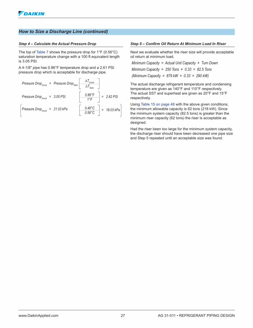
Step 4 – Calculate the Actual Pressure Drop
The top of Table 7 shows the pressure drop for 1°F (0.56°C) saturation temperature change with a 100 ft equivalent length is 3.05 PSI.
A 4-1/8" pipe has 0.86°F temperature drop and a 2.61 PSI pressure drop which is acceptable for discharge pipe.
Step 5 – Confirm Oil Return At Minimum Load In Riser
Next we evaluate whether the riser size will provide acceptable oil return at minimum load.
Minimum Capacity = Actual Unit Capacity × Turn DownMinimum Capacity = 250 Tons × 0.33 = 82.5 Tons(Minimum Capacity = 879 kW × 0.33 = 290 kW)
The actual discharge refrigerant temperature and condensing temperature are given as 140°F and 110°F respectively. The actual SST and superheat are given as 20°F and 15°F respectively.
Using Table 15 on page 48 with the above given conditions, the minimum allowable capacity is 62 tons (218 kW). Since the minimum system capacity (82.5 tons) is greater than the minimum riser capacity (62 tons) the riser is acceptable as designed.
Had the riser been too large for the minimum system capacity, the discharge riser should have been decreased one pipe size and Step 5 repeated until an acceptable size was found.
∆TActual = ∆TTableActual LengthTable Length
Actual CapacityTable Capacity
1.8
∆TActual = 1°F
∆TActual = 0.56°C
= 0.86°F110.0 ft100.0 ft
250.0 Tons287.0 Tons
1.8
= 0.48°C35.5 m30.5 m
879 kW1009 kW
1.8
Discharge Line — Step 3
Pressure DropActual = Pressure DropTable
∆TActual
∆TTable
Pressure DropActual = 3.05 PSI
Pressure DropActual = 21.03 kPa
= 2.62 PSI0.86°F1°F
= 18.03 kPa0.48°C0.56°C
Liquid Line — Step 4
AG 31-011 • REFRIGERANT PIPING DESIGN 28 www.DaikinApplied.com
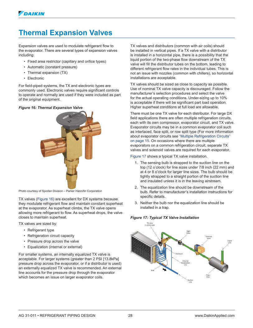
Thermal Expansion ValvesExpansion valves are used to modulate refrigerant flow to the evaporator. There are several types of expansion valves including:
• Fixed area restrictor (capillary and orifice types) • Automatic (constant pressure) • Thermal expansion (TX) • Electronic
For field-piped systems, the TX and electronic types are commonly used. Electronic valves require significant controls to operate and normally are used if they were included as part of the original equipment.
Figure 16: Thermal Expansion Valve
Photo courtesy of Sporlan Division – Parker Hannifin Corporation
TX valves (Figure 16) are excellent for DX systems because they modulate refrigerant flow and maintain constant superheat at the evaporator. As superheat climbs, the TX valve opens allowing more refrigerant to flow. As superheat drops, the valve closes to maintain superheat.
TX valves are sized by:
• Refrigerant type • Refrigeration circuit capacity • Pressure drop across the valve • Equalization (internal or external)
For smaller systems, an internally equalized TX valve is acceptable. For larger systems (greater than 2 PSI [13.8kPa] pressure drop across the evaporator, or if a distributor is used) an externally equalized TX valve is recommended. An external line accounts for the pressure drop through the evaporator which becomes an issue on larger evaporator coils.
TX valves and distributors (common with air coils) should be installed in vertical pipes. If a TX valve with a distributor is installed in a horizontal pipe, there is a possibility that the liquid portion of the two-phase flow downstream of the TX valve will fill the distributor tubes on the bottom, leading to different refrigerant flow rates in the individual tubes. This is not an issue with nozzles (common with chillers), so horizontal installations are acceptable.
TX valves should be sized as close to capacity as possible. Use of nominal TX valve capacity is discouraged. Follow the manufacturer’s selection procedures and select the valve for the actual operating conditions. Under-sizing up to 10% is acceptable if there will be significant part load operation. Higher superheat conditions at full load are allowable.
There must be one TX valve for each distributor. For large DX field applications there are often multiple refrigeration circuits, each with its own compressor, evaporator circuit, and TX valve. Evaporator circuits may be in a common evaporator coil such as interlaced, face split, or row split type (For more information about evaporator circuits see “Multiple Refrigeration Circuits” on page 15. On occasions where there are multiple evaporators on a common refrigeration circuit, separate TX valves and solenoid valves are required for each evaporator.
Figure 17 shows a typical TX valve installation.
1. The sensing bulb is strapped to the suction line on the top (12 o’clock) for line sizes under 7/8 inch (22 mm) and at 4 or 8 o’clock for larger line sizes. The bulb should be tightly strapped to a straight portion of the suction line and insulated unless it is in the leaving airstream.
2. The equalization line should be downstream of the bulb. Refer to manufacturer’s installation instructions for specific details.
3. Neither the bulb nor the equalization line should be installed in a trap.
Figure 17: Typical TX Valve Installation TX valve
in vertical pipe
SightGlass
SolenoidValve
LiquidLine
Filter-Drier
Distributor
ExternalEqualization
Line
SuctionLine
Bulb
www.DaikinApplied.com 29 AG 31-011 • REFRIGERANT PIPING DESIGN
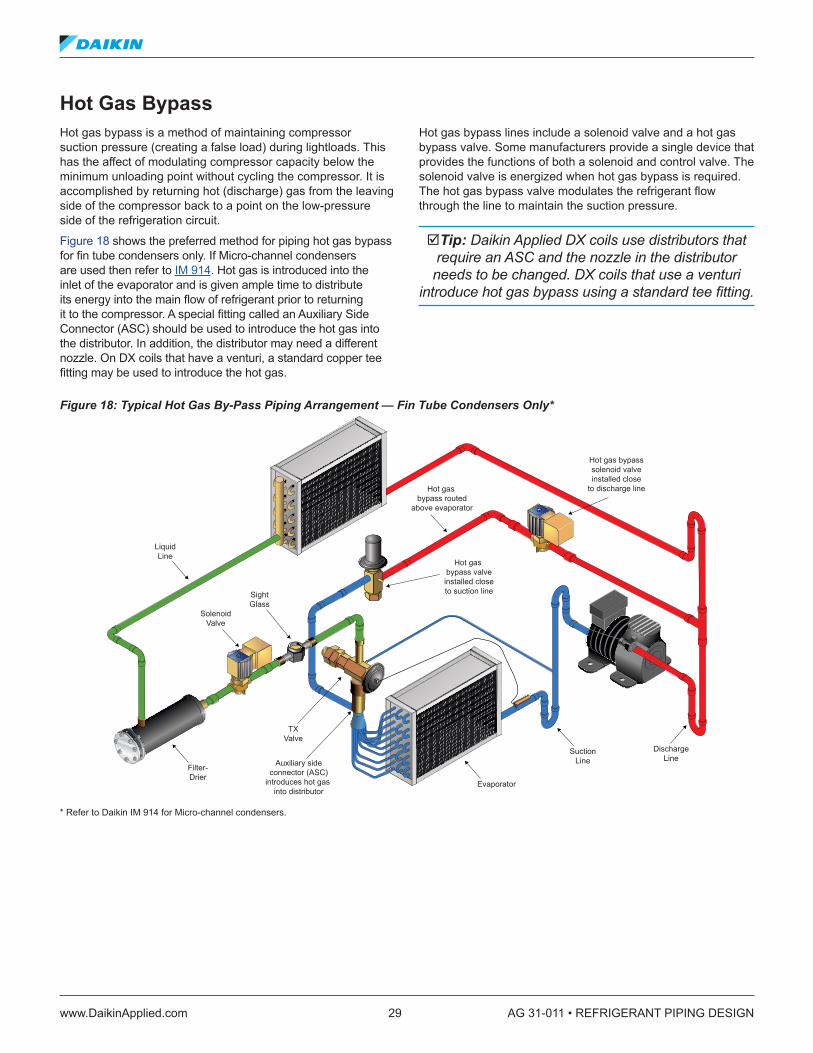
Hot Gas BypassHot gas bypass is a method of maintaining compressor suction pressure (creating a false load) during lightloads. This has the affect of modulating compressor capacity below the minimum unloading point without cycling the compressor. It is accomplished by returning hot (discharge) gas from the leaving side of the compressor back to a point on the low-pressure side of the refrigeration circuit.
Figure 18 shows the preferred method for piping hot gas bypass for fin tube condensers only. If Micro-channel condensers are used then refer to IM 914. Hot gas is introduced into the inlet of the evaporator and is given ample time to distribute its energy into the main flow of refrigerant prior to returning it to the compressor. A special fitting called an Auxiliary Side Connector (ASC) should be used to introduce the hot gas into the distributor. In addition, the distributor may need a different nozzle. On DX coils that have a venturi, a standard copper tee fitting may be used to introduce the hot gas.
Hot gas bypass lines include a solenoid valve and a hot gas bypass valve. Some manufacturers provide a single device that provides the functions of both a solenoid and control valve. The solenoid valve is energized when hot gas bypass is required. The hot gas bypass valve modulates the refrigerant flow through the line to maintain the suction pressure.
Tip: Daikin Applied DX coils use distributors that require an ASC and the nozzle in the distributor needs to be changed. DX coils that use a venturi
introduce hot gas bypass using a standard tee fitting.
Figure 18: Typical Hot Gas By-Pass Piping Arrangement — Fin Tube Condensers Only*
* Refer to Daikin IM 914 for Micro-channel condensers.
LiquidLine
SightGlass
SolenoidValve
Filter-Drier
SuctionLine
DischargeLine
TXValve
Auxiliary sideconnector (ASC)
introduces hot gas into distributor
Evaporator
Hot gas bypasssolenoid valveinstalled close
to discharge line
Hot gas bypass valveinstalled closeto suction line
Hot gas bypass routed
above evaporator

AG 31-011 • REFRIGERANT PIPING DESIGN 30 www.DaikinApplied.com
Hot Gas Bypass Line SizingHot gas piping should be sized using the discharge gas line sizing tables found in Appendix 2 (page 40). It is best to undersize hot gas bypass lines, keeping them as short as possible, to limit the line volume. During OFF cycles, the vapor refrigerant will condense and may create a slug of refrigerant when the hot gas bypass valve opens. A rule of thumb is use one line size smaller than the recommended discharge table line size because hot gas bypass lines are short. Once the line size is selected, the actual temperature and pressure drop should be checked. The line pressure drop should be small relative to the pressure drop across the valve. The line should be pitched 1/8 inch per foot (10.4 mm/m) in the direction of refrigerant flow.
The hot gas bypass valve and solenoid should be located as close to the discharge line as possible. This will minimize the amount of hot gas that may condense upstream of the valve and solenoid.
The hot gas bypass line should be routed above the evaporator and introduced to the ASC from the side to reduce oil scavenging. The line should be insulated and a check valve added if the ambient temperature is lower than the saturated suction temperature.
Hot Gas Bypass ValvesHot gas bypass (HGBP) valves used with distributor-type DX coils should be externally equalized. Their purpose is to maintain minimum suction pressure to the compressor. This is best done when the valve is responding to suction pressure. Over sizing the HGBP valve may cause:
• System inversion • Loss of oil management• Prevent the compressor from cycling OFF (overheating) • Poor efficiency
Hot gas valve selection is based on;
• Refrigerant type • Minimum allowable evaporating temperature at reduced
load – typically 32 to 34°F (0.0 to 1.1°C) for chillers and 26 to 28°F (-3.3 to -2.2°C) for air conditioners
• Minimum compressor capacity • Minimum system capacity. For air conditioning
applications, minimum load with hot gas bypass use should be limited to approximately 10% of a system’s capacity. Some process applications will require unloading down to zero
• Condensing temperature at minimum load – typically 80°F (26.7°C).
Hot gas bypass valves must be sized for the difference between the minimum compressor capacity and the minimum system capacity. If the minimum system capacity is zero, then the hot gas bypass valve should be sized for the minimum compressor capacity.
The example provided here is based on Sporlan products. For other manufacturers, refer to their installation and application guides.
Sporlan valves begin to open at approximately 6°F (3.3°C) above the minimum evaporator temperature and remain open at the rated capacity of the minimum evaporator temperature. The actual pressure which the valve will open at depends on the refrigerant.
When remote condensers are used, always layout and size the condenser piping before selecting the HGBP valve. During light loads, when the HGBP valve is open, the remaining velocity in the discharge line may be so low that oil becomes trapped.
Figure 19: Hot Gas Bypass Accessories
Photos courtesy of Sporlan Division – Parker Hannifin Corporation
Aux SideConnector
Discharge Bypass Valve Solenoid Valve
Discharge Bypass Valve

www.DaikinApplied.com 31 AG 31-011 • REFRIGERANT PIPING DESIGN
Table 3: Hot Gas Bypass Valve Sizing ChartDirect Acting Discharge Bypass Valve Capacities (Tons) Capacities based on discharge temperatures 50°F above is entropic compression, 25°F superheat at the compressor, 10°F sub-cooling, and includes both the hot gas bypassed and liquid refrigerant for desuperheating, regardless of whether the liquid is fed through the system thermostatic expansion valves or an auxiliary desuperheating thermostatic expansion valve.
Ref
riger
ant
Valv
e Ty
pe
Adj
ustm
ent
Ran
ge (p
sig) Minimum Allowable Evaporator Temperature at the Reduced Load (°F)
40 26 20 0 -20 -40Condensing Temperature (°F)
80 100 120 80 100 120 80 100 120 80 100 120 80 100 120 80 100 120Adjustable Models
22
ADRI-1-1/4ADRIE-1-1/4
0/55 — — — 0.34 0.044 0.56 0.41 0.52 0.66 0.49 0.63 0.79 0.46 0.59 0.75 0.43 0.56 0.700/75 0.45 0.58 0.73 0.50 0.64 0.81 0.50 0.65 0.81 0.47 0.60 0.76 0.39 0.50 0.63 0.33 0.42 0.54
0/100 0.41 0.53 0.67 0.42 0.54 0.67 0.41 0.53 0.66 0.38 0.49 0.62 0.34 0.44 0.56 0.31 0.40 0.50ADRS-2
ADRSE-20/30 — — — — — — — — — 3.02 3.90 4.91 2.91 3.75 4.74 2.81 3.63 4.580/80 2.73 3.51 4.42 2.77 3.57 4.50 2.79 3.59 4.53 2.84 3.66 4.61 2.83 3.65 4.60 2.71 3.50 4.42
ADRP-3ADRPE-3
0/30 — — — — — — — — — 10.8 13.9 17.6 10.9 14.1 17.8 10.5 13.5 17.10/80 7.12 9.16 11.5 7.69 9.90 12.5 7.92 10.2 12.8 8.44 10.9 13.7 8.55 11.0 13.9 8.24 10.6 13.5
ADRHE-60/30 — — — — — — — — — 10.8 13.9 17.6 10.9 14.1 17.8 10.5 13.5 17.10/80 7.12 9.16 11.5 7.69 9.90 12.5 7.92 10.2 12.8 8.44 10.9 13.7 8.55 11.0 13.9 8.24 10.6 13.5
134a
ADRI-1-1/4ADRIE-1-1/4
0/55 0.30 0.40 0.51 0.31 0.41 0.53 0.31 0.41 0.53 0.29 0.38 0.49 — — — — — —0/75 0.32 0.43 0.55 0.30 0.39 0.50 0.28 0.37 0.48 0.23 0.31 0.40 — — — — — —
0/100 0.26 0.34 0.44 0.24 0.32 0.41 0.24 0.31 0.40 0.21 0.28 0.36 — — — — — —ADRS-2
ADRSE-20/30 — — — 1.97 2.60 3.34 1.94 2.56 3.30 1.87 2.46 3.18 — — — — — —0/80 2.02 2.67 3.43 1.85 2.44 3.15 1.85 2.44 3.15 — — — — — — — — —
ADRP-3ADRPE-3
0/30 — — — 3.75 4.95 6.38 3.76 4.96 6.39 3.70 4.89 6.31 — — — — — —0/80 3.74 4.94 6.37 3.35 4.42 5.70 3.36 4.43 5.71 — — — — — — — — —
ADRHE-60/30 — — — 7.09 9.36 12.1 7.09 9.37 12.1 7.12 9.41 12.1 — — — — — —0/80 7.07 9.34 12.0 5.50 7.26 9.36 5.53 7.31 9.41 — — — — — — — — —
407C
ADRI-1-1/4ADRIE-1-1/4
0/55 — — — 0.48 0.61 0.77 0.54 0.69 0.86 0.58 0.74 0.93 0.53 0.68 0.85 — — —0/75 0.61 0.78 0.97 0.61 0.78 0.97 0.60 0.77 0.96 0.53 0.68 0.85 0.43 0.56 0.69 — — —
0/100 0.51 0.65 0.81 0.50 0.63 0.79 0.48 0.62 0.77 0.44 0.56 0.70 0.39 0.50 0.62 — — —ADRS-2
ADRSE-20/30 — — — — — — — — — 3.52 4.51 5.63 3.38 4.33 5.41 — — —0/80 3.32 4.25 5.30 3.32 4.25 5.30 3.33 4.27 5.32 3.36 4.31 5.38 3.30 4.23 5.28 — — —
ADRP-3ADRPE-3
0/30 — — — — — — — — — 6.74 8.63 10.8 6.74 8.64 10.8 — — —0/80 5.86 7.50 9.36 5.86 7.50 9.36 5.95 7.61 9.50 6.10 7.81 9.75 6.02 7.71 9.63 — — —
ADRHE-60/30 — — — — — — — — — 12.7 16.3 20.3 12.8 16.5 20.5 — — —0/80 9.43 12.1 15.1 9.43 12.1 15.1 9.67 12.4 15.5 10.1 13.0 16.2 10.1 12.9 16.1 — — —
This table courtesy of Sporlan Division – Parker Hannifin Corporation. It is only included for the example. Please refer to manufacturers data for sizing and application.

AG 31-011 • REFRIGERANT PIPING DESIGN 32 www.DaikinApplied.com
How to Size a Hot Gas Bypass Line
Size the hot gas bypass line and valve for the following air conditioner with a fin tube condenser.
The system:
• Uses R-407C • Capacity is a 30 ton air conditioner with tandem scroll
compressors • Minimum capacity is 5 tons (17.6 kW) • Minimum compressor capacity of 15 tons (52.8 kW) or
one compressor • Evaporator operates at 26°F (-3.3°C) • Condenser operates at 120°F (48.9°C) that drops to 80°F
(26.7°C) during minimum load • Equivalent length is 10 ft (3.0 m)
Step 1 – Estimate HGBP Valve Capacity
HGBP Valve = Minimum Compressor Capacity – Minimum System Capacity
HGBP Valve = 15 Tons – 5 Tons = 10 Tons(HGBP Valve = 52.8 kW – 17.6 kW = 35.2 kW)
Step 2 – Select a HGBP Valve
Table 3 on page 31 shows the Sporlan rating table for ADRHE series of HGBP valves. Given a 10 ton capacity, 26°F evaporator temperature, 80°F condensing temperature we can see a ADRHE-6 can deliver 9.43 tons (33.1 kW) and can use a 5/8, 7/8, or 1-1/8 inch solder connection.
Step 3 – Estimate HGBP Piping Size
Table 10 on page 45 can be used to determine the hot gas bypass line size for R-407C. For 10 tons 1-1/8 inch line delivers 8.5 tons (29.8 kW) at 20°F (-6.67°C) SST and table rating conditions. The equivalent length of this application is only 10% of the table rating condition. A 1-1/8-inch (29 mm) pipe will deliver much more capacity at such a short length. Let’s consider a 7/8-inch (22 mm) line which delivers 4.2 tons (14.7 kW).
Sizing the pipe for full load requires a correction for the 80°F (26.7°C) actual condenser temperature. Referring to the correction factors at the bottom of Table 10;
Actual Capacity = Table Capacity × 0.787Actual Capacity = 4.2 Tons × 0.787 = 3.31 Tons(Actual Capacity = 14.8 kW × 0.787 = 11.65 kW)
Step 4 – Calculate the Actual ∆T
Using Note #5 in the table, we can calculate the saturation temperature difference based upon the actual design conditions.
Step 5 – Calculate the Actual Pressure Drop
The top of Table 10 shows the pressure drop for 1°F (0.56°C) saturation temperature change with a 100 ft equivalent length is 3.3 PSI.
A 7/8-inch (22 mm) line provides a satisfactory pressure drop and keeps the line volume to a minimum. For point of comparison, a 1-1/8 inch (29 mm) line would have provided a pressure drop of 0.65 PSI (4.48 kPa). This would have been an acceptable pressure drop, but the volume would have been greater. A 5/8-inch (16 mm) line would have had a 13.5 PSI (93.1 kPa) drop and the refrigerant velocity would have caused excessive noise.
In addition to the HGBP valve we require:
• A 7/8 inch (22 mm) solenoid • An ASC for the distributor • A new nozzle for the distributor
Recall that the HGBP valve begins to open at 6°F (3.3°C) above SST, or in this case 32°F (0°C). By the time SST is 26°F (-3.3°C) the HGBP valve will be passing the equivalent of 10 tons (35.2 kW) of R-407C refrigerant from the discharge line to the inlet of the evaporator.
∆TActual = ∆TTableActual LengthTable Length
Actual CapacityTable Capacity
1.8
∆TActual = 1°F
∆TActual = 0.56°C
= 0.732°F10.0 ft100.0 ft
10.0 Tons31.1 Tons
1.8
= 0.40°C3.0 m30.5 m
35.2 kW11.7 kW
1.8
HGBP Line — Step 4
Pressure DropActual = Pressure DropTable
∆TActual
∆TTable
Pressure DropActual = 3.3 PSI
Pressure DropActual = 28.8 kPa
= 2.42 PSI0.732°F1°F
= 16.3 kPa0.40°C0.56°C
HGBP Line — Step 5
www.DaikinApplied.com 33 AG 31-011 • REFRIGERANT PIPING DESIGN
Installation Details
Pump DownSome air conditioning systems are designed with either recycling or a one-time pumpdown cycle. These systems have a condenser sized large enough to hold the refrigerant charge. When cooling is no longer required, a solenoid valve in the liquid line closes. The compressor continues operating until the suction pressure drops below the suction pressure cutout switch.Once the suction pressure switch opens, the compressor stops. One-time pump down systems stay OFF until there is a need for cooling. Recycling pump down allows the compressor to restart if the suction pressure switch closes, even if cooling is unnecessary. The solenoid is still closed (no cooling required) so the compressor will quickly lower the suction pressure to where the pressure switch opens again. An example of this is the Daikin Applied RPS C-vintage Applied Rooftop System.
The advantage of pump down is that most of the refrigerant in the evaporator is removed. Without pump down, during the OFF cycle, the refrigerant may migrate to the evaporator and/or suction line. On startup, the liquid refrigerant may be drawn into the compressor and cause slugging. If the casing of the compressor is allowed to get colder than the rest of the circuit, refrigerant throughout the circuit may migrate to the compressor crankcase, condense and cause flooded starts.
Systems that do not have pump down may still have a solenoid that closes while the compressor is OFF to limit refrigerant migration. Crankcase heaters may also be added to help raise the compressor temperature and avoid refrigerant condensation.
When pump down is part of the equipment design, a solenoid valve will be required in the liquid line as shown in Figure 17 on page 28. It should be installed as close to the evaporator as possible, just before the TX valve. With pump down, the condenser must be able to hold the system charge. Long field refrigerant piping arrangements may increase the refrigerant volume above the capacity of the condenser and limit service pump down. A receiver may be added to store the refrigerant. Consult the manufacturer if a receiver is required.
Piping InsulationSuction lines are cold, 40°F (4.4°C) SST, and cause condensation, even in conditioned spaces. In addition, any heat that enters the refrigerant adds to the superheat and reduces system efficiency. For these reasons, suction lines should be insulated with a vapor proof insulation. This is a requirement of many building codes. Rubratex® is the most common form of refrigerant line insulation.
Liquid lines generally are insulated. They are warm to hot (110°F [43.3°C] for air-cooled). If liquid lines pass through a space that is warmer than the refrigerant (i.e. the roof of a building at roof level), or if they could be considered hot enough to pose a safety risk, then insulation should be added.
Discharge lines are generally uninsulated. They may be very hot, in excess of 150°F (66°C), so insulation may be warranted as a safety consideration, or if the heat loss from the discharge gas line would be considered objectionable to the space.
Hot gas bypass lines should be insulated, especially if the runs are long or if the piping is exposed to cold temperatures.
Refrigerant Line InstallationRefrigerant lines need to be securely installed to minimize vibration that causes noise and damages piping. Reciprocating compressors, in particular, cause vibration. Steel braided flexible refrigerant lines (a must for spring isolated reciprocating compressors) minimize this vibration. Follow manufacturer’s instructions when using steel braided lines. Discharge mufflers are also occasionally used on discharge lines to minimize gas pulsations.
Refrigerant lines that rub against solid objects wear holes through copper and create a leak. For this reason, when refrigerant lines pass through walls, the line should pass through sleeved openings in such a manner that the lines do not touch.
There are several commercially available pipe clamping systems that allow pipes to be held rigid without causing damage to them. Most include some form of rubber grommet around the pipe, which is then secured within a bracket. Many building codes specify minimum support spacing.
Piping should also be protected from mechanical damage. Where piping is exposed to possible damage, the lines should be routed out of the way or be protected in some form of chase. Burying refrigerant lines should be avoided.

AG 31-011 • REFRIGERANT PIPING DESIGN 34 www.DaikinApplied.com
Low Ambient OperationRefrigeration circuit components are sized for the most demanding application point. This is typically when the ambient temperature is high and the evaporator temperature is low. Many systems are required to operate properly when the ambient temperature is much lower.The issue here is the condenser becomes “too efficient” and lowers the liquid temperature and pressure beyond the range that the TX valve compensates for. In these applications, some form of low ambient control is required.
Water-cooled systems typically use some form of condenser water bypass line to maintain head pressure. For air-cooled systems, there are three common approaches to design for low ambient operation:
• Fan cycling • Fan speed control• Condenser flood back
Fan Cycling and Fan Speed Control Fan cycling and fan speed control are the most common forms of low ambient operation for commercial air conditioning systems. Fan cycling entails staging condenser fans ON and OFF based on the ambient temperature or the head pressure. Ambient-based control is cost-effective, but should only be used with air conditioning applications. Process loads must use pressure-based controls.
Fan speed control entails using some form of fan speed controller to modulate air-flow through the condenser. Fan speed is usually based on head pressure.
Both of these approaches are options provided by the equipment manufacturer and have minimal impact upon the piping system design, other than requiring a port for the head pressure sensor.
Condenser Flood Back DesignFigure 20 shows a typical condenser flood back arrangement. As the ambient temperature drops, the head pressure drops. A head pressure control valve (refrigerant flow regulator) controlled by head pressure begins to close, restricting flow of liquid refrigerant from the condenser. Liquid refrigerant “floods” the condenser. As the tubes in the condenser flood, they reduce the surface area available for condensation and reduce the heat rejection capacity. As the condenser floods, the head pressure climbs until it reaches the setting of the head pressure control valve.
Single head pressure control valve arrangements are available from several manufacturers. Refer to the manufacturers instructions for sizing and applications.
A receiver is required to store refrigerant during warmer weather. The receiver should be sized so it is at 80% of capacity while containing the entire system charge. Another aspect of receivers is that they contain both liquid and gaseous refrigerant at the same time. By their design, receivers prohibit liquid subcooling from occurring. Without liquid subcooling the capacity of the system is reduced and care must be taken in the design of the liquid line to avoid flashing at the TX valve.
Flooded systems are an excellent method of providing head pressure control in cold climates, but they increase initial cost, add complexity to the refrigeration system, increase installation time, and increase the refrigerant charge. The loss of subcooling should be recognized. If a flooded system is required, consult the manufacturer prior to installation.
Tip: Flooded systems with receivers are complex. Consult the manufacturer for assistance
before installing.

www.DaikinApplied.com 35 AG 31-011 • REFRIGERANT PIPING DESIGN
Figure 20: Typical Condenser Flood Back Arrangement
HeadPressure
Control Valve
DischargeLine
LiquidLine
Receiver
CondenserCoil

AG 31-011 • REFRIGERANT PIPING DESIGN 36 www.DaikinApplied.com
Safety and the EnvironmentRefrigeration systems contain fluids under pressure at dangerous temperatures and pressures. Proper safety procedures must be followed to provide a system that is acceptable. ASHRAE Standard 15, Safety Code for Mechanical Refrigeration and ASME Standard B31.5, Refrigeration Piping should be followed. Most building codes require adherence to these standards.
Technicians should also be EPA or other government agency certified to handle refrigerants.
www.DaikinApplied.com 37 AG 31-011 • REFRIGERANT PIPING DESIGN
Appendix 1 — GlossaryAccumulator (Suction): A device installed just before a compressor in the suction line that is used to separate vapor refrigerant from liquid refrigerant and oil. They are common in heat pumps and industrial refrigeration applications.
Adiabatic Process: A process where energy gain to the surroundings is zero. Enthalpy remains constant for the fluid. An example is the refrigeration expansion process.
ASC (Auxiliary Side Connector): A fitting used in conjunction with a distributor to introduce hot gas refrigerant into the distributor for hot gas bypass.
Azeotropic Refrigerants: Refrigerant blends that behave as a single substance. An example is R410A.
Carnot Cycle: The ideal, reversible heat cycle between two infinite heat sinks.
Check Valve: A valve that only allows flow in one direction. Used in refrigeration systems to stop refrigerant migration when the system is OFF.
Compressor: A component in a refrigeration system that compresses refrigerant vapor to a higher pressure and temperature and consumes power to do so.
Condenser: A component in a refrigeration system where refrigerant is condensed from a gas to a liquid and heat is rejected to the surroundings.
COP (Coefficient of Performance): The measure of the refrigeration system efficiency. Defined as refrigeration effect per compressor power.
Critical Point: The point on a P-H Diagram where the saturated liquid and saturated vapor lines meet. Above the critical point, condensation cannot occur.
Density (d): The mass of a substance divided by the volume that substance occupies. It is measured in pounds per cubic foot (lb/ft³) or kilograms per meter cubed (kg/m³).
Desuperheater: A device that removes superheat from either the suction or discharge gas line. This heat may be used in a heat recovery application such as hot water heating.
Direct Expansion (DX) Evaporator: An evaporator where the refrigerant is in the tubes. Used for either refrigerant to air coils or chillers.
Discharge (hot gas) Line: A refrigerant line that carries superheated, high pressure refrigerant from the compressor to the condenser.
Discharge Muffler: Used to reduce sound and pulsations inrefrigerant lines. They are typically installed in discharge lines near the compressor.
Distributor: A device that feeds two phase refrigerant evenly to each tube of a DX evaporator. It is usually part of the coil and is directly down stream of the TX valve.
Economizer (Refrigerant): A form of two stage refrigeration cycle where the compressor has a port that allows refrigerant at an intermediate pressure to be injected into the compression process.
EER (Energy Efficiency Ratio): Refrigeration effect in British thermal units per hour per power input in watts (Btu/hr•W).
Enthalpy (h): The measure of energy content in a fluid. Measured in British thermal units per pound (Btu/lb).
Entropy (s): The measure of molecular disorder of a substance. A process without change in entropyis considered ideal and reversible. Measured in British Thermal Units per pound–degree Rankin (Btu/lb°R)
Evaporator: A component in a refrigeration system where refrigerant is boiled from a liquid to gas and heat is absorbed from the surroundings. It is the component that performs the cooling effect.
Expansion Device: A component that reduces the pressure and temperature adiabatically in a refrigeration system. There are several types but a thermal expansion (TX) valve is most common for air conditioning applications. The device is located in the liquid line as close to the evaporator as possible.
Filter-Drier: A device used to filter refrigerant to remove contaminants. It also contains a desiccant that removes moisture from the refrigerant. Installed on liquid and/or suction lines.
Flashing: Partial or total vaporization obtained by sudden reduction of pressure.
Flash Tank: A component in a refrigeration system used to separate liquid refrigerant from vapor at an intermediate pressure. Commonly used in two stage refrigeration cycles.
Floodback: A process where liquid refrigerant forms and moves to the lowest or coldest part of the refrigerant circuit. When unplanned for, floodback is detrimental to the operation of the refrigeration system.
Flooded Evaporator: For chiller evaporators, the refrigerant is outside the tubes and all the tubes are submersed in liquid refrigerant.
Glide: The change in volumetric composition and saturation temperature experienced by Zeotropic refrigerants during boiling.
Head Pressure Control Valve: A pressure regulating valve that diverts flow around the condenser as the pressure drops. This is used as part of liquid flood back head pressure control system.
Hot Gas Bypass: A method of maintaining suction pressure to the compressor during periods of light load by recirculating discharge gas from the leaving side of the compressor back to either the inlet of the evaporator or the suction line.

AG 31-011 • REFRIGERANT PIPING DESIGN 38 www.DaikinApplied.com
Hot Gas Reheat: A method of reheating supply air after it has been cooled by using a second coil down stream of the evaporator and passing discharge gas from the compressor through it.
Intercooler: A component in a refrigeration system used to desuperheat compressed refrigerant with cool liquid refrigerant. Commonly used in two stage refrigeration cycles to cool refrigeration from the booster compressor.
Isentropic Efficiency (ŋs): Measure of compressor efficiency defined as ∆hisnetropic / ∆hactual
Isentropic Process: A process where the entropy remains constant. Such a process is said to be reversible and cannot be more efficient. An example is isentropic compression (which cannot actually occur but is used as a benchmark to measure actual compressor performance against – See isentropic efficiency.)
Isobaric Process: A process that occurs at constant pressure. An example is evaporation in the evaporator.
Isolators: Components used to stop vibration and noise from passing beyond the source. There are isolators for compressors and refrigerant piping. Compressor isolators are rubber in shear (RIS) or spring. Refrigerant piping isolators are usually rubber grommets used with a clamping system.
Isothermal Process: A process that occurs at constant temperature. An example is evaporation in the evaporator.
Liquid Floodback Head Pressure Control: A method of maintaining proper head pressure during low ambient operation by flooding the condenser with liquid refrigerant and reducing the effective heat transfer surface of the condenser.
Liquid Line: A refrigerant line that moves liquid high pressure refrigerant from the condenser to an expansion device.
Liquid Overfeed System: An evaporator where the refrigerant is mechanically pumped faster than it is boiled so liquid refrigerant exits the evaporator. The mixture leaving the evaporator enters a low pressure receiver where the vapor is drawn off to the compressor and the liquid is returned to the evaporator. This arrangement is common in industrial applications.
Liquid Subcooling Reheat: A method of reheating supply air after it has been cooled by using a second coil down stream of the evaporator and passing liquid refrigerant from the condenser through it.
Low Ambient Control: A control process that maintains condenser pressure at an acceptable level during periods of low ambient temperature and/or load. Examples include, fan cycling, fan speed control, and liquid flood back control.
Mass (m): The quantity of a substance present. It is measured in pounds or lbm or kilograms ( kg).
Oil Separator: A vessel in a refrigeration circuit used to separate oil from refrigerant. They are usually in the discharge line. The oil is returned to the compressor sump.
Pressure (p): Force over unit area. Bursts pipes or expands balloons. It is measured in pounds per square inch (PSI) or Pascals (Pa).
Quality (X): The ratio of vapor mass to liquid mass refrigerant during evaporation and/or condensation.
Receiver: A container used to store liquid refrigerant. Typically used when the condenser cannot hold the refrigerant charge or for liquid flood back low ambient control.
Reversing Valve: A device in a refrigeration circuit used to convert an air conditioner into a heat pump. When powered, the reversing valve will switch the evaporator and condenser to reverse the rejection of heat.
Riser: A refrigerant pipe that runs vertically.
Rubatex®: A brand name for a moisture proof expanded rubber insulation commonly used on refrigerant piping for thermal insulation.
Saturation Condition: A state where liquid and vapor refrigerant are in direct contact with each other and all properties remain unchanged overtime. When a refrigerant is in saturation condition there can be only one temperature for a given pressure and visa versa.
Saturated Condensing Temperature: The saturation condition that exists in the condenser.
Saturated Suction Temperature: The saturation condition that exists in the evaporator.
Service Valve: A refrigerant valve that can be manually closed to isolate part of a refrigeration circuitfor servicing.
Sight Glass: A refrigerant piping fitting that has a window to allow viewing of the refrigerant. They are used in the liquid line as close to the TX valve as possible to visualize vapor bubbles. Some sight glasses include a moisture indicator used to mark the presences of moisture in the refrigeration system.
Solenoid Valve: A two position valve (open with power, closed without power) commonly used in refrigerant piping systems to isolate a section of the refrigerant circuit. Also used in pump down and hot gas bypass arrangements.
Specific Heat (cp): The energy needed to raise the temperature of a unit of mass one degree of temperature. Measured in Btu/lbm°F or (kJ/(kg°C))
Sub-cooled Liquid: A liquid that has been cooled below the saturation condition resulting in lower temperature and enthalpy. This is used to offset pressure losses in liquid lines that lead to flashing and to increase the capacity of the refrigeration circuit.

www.DaikinApplied.com 39 AG 31-011 • REFRIGERANT PIPING DESIGN
Suction Line: A refrigerant line that carries low pressure refrigerant vapor from the evaporator to the compressor.
Superheated Vapor: A vapor that has been heated beyond the saturation condition resulting in increased temperature and enthalpy. This is done to make sure the refrigerant in the suction line entering the compressor is truly a vapor.
Temperature (T): Represents the average motion of the molecules in the fluid. It is measured in °F (Fahrenheit) or °C (Celsius).
Thermal Expansion (TX) Valve: A pressure regulating valve used in refrigeration systems to lower the liquid refrigerant pressure from the condensing pressure to the evaporation pressure. Thermal expansion valves modulate refrigerant flow based on superheat in the suction line.
Trap: A “P” shaped piping fitting that holds either liquid refrigerant or oil.
Venturi: An alternative device to a distributor for feeding two phase refrigerant flow into each tube of a DX evaporator. It is usually part of the coil and is directly down stream of the TX valve.
Volume (V): The geometrical space occupied by a fluid. It is measured in cubic feet (ft³) or cubic meters (m³)
Volumetric Efficiency (ŋva): Measure of compressor performance defined as actual volume flow rate/ideal volume flow rate.
Zeotropic Refrigerants: Refrigerant blends where the components do not behave asone substance. Zeotropic refrigerants experience glide. An example is R-407C.
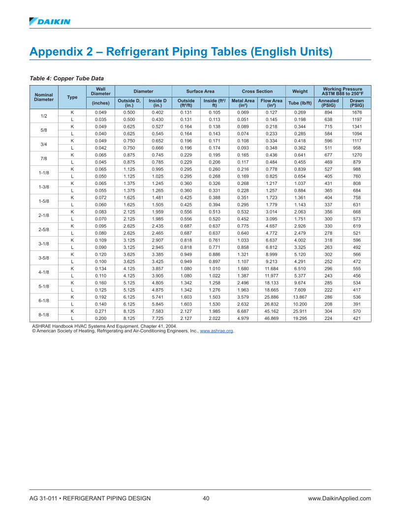
AG 31-011 • REFRIGERANT PIPING DESIGN 40 www.DaikinApplied.com
Appendix 2 – Refrigerant Piping Tables (English Units)
Table 4: Copper Tube Data
Nominal Diameter Type
Wall Diameter Diameter Surface Area Cross Section Weight Working Pressure
ASTM B88 to 250°F
(inches) Outside D, (in .)
Inside D (in .)
Outside (ft²/ft)
Inside (ft²/ft)
Metal Area (in²)
Flow Area (in²) Tube (lb/ft) Annealed
(PSIG)Drawn (PSIG)
1/2K 0.049 0.500 0.402 0.131 0.105 0.069 0.127 0.269 894 1676L 0.035 0.500 0.430 0.131 0.113 0.051 0.145 0.198 638 1197
5/8K 0.049 0.625 0.527 0.164 0.138 0.089 0.218 0.344 715 1341L 0.040 0.625 0.545 0.164 0.143 0.074 0.233 0.285 584 1094
3/4K 0.049 0.750 0.652 0.196 0.171 0.108 0.334 0.418 596 1117L 0.042 0.750 0.666 0.196 0.174 0.093 0.348 0.362 511 958
7/8K 0.065 0.875 0.745 0.229 0.195 0.165 0.436 0.641 677 1270L 0.045 0.875 0.785 0.229 0.206 0.117 0.484 0.455 469 879
1-1/8K 0.065 1.125 0.995 0.295 0.260 0.216 0.778 0.839 527 988L 0.050 1.125 1.025 0.295 0.268 0.169 0.825 0.654 405 760
1-3/8K 0.065 1.375 1.245 0.360 0.326 0.268 1.217 1.037 431 808L 0.055 1.375 1.265 0.360 0.331 0.228 1.257 0.884 365 684
1-5/8K 0.072 1.625 1.481 0.425 0.388 0.351 1.723 1.361 404 758L 0.060 1.625 1.505 0.425 0.394 0.295 1.779 1.143 337 631
2-1/8K 0.083 2.125 1.959 0.556 0.513 0.532 3.014 2.063 356 668L 0.070 2.125 1.985 0.556 0.520 0.452 3.095 1.751 300 573
2-5/8K 0.095 2.625 2.435 0.687 0.637 0.775 4.657 2.926 330 619L 0.080 2.625 2.465 0.687 0.637 0.640 4.772 2.479 278 521
3-1/8K 0.109 3.125 2.907 0.818 0.761 1.033 6.637 4.002 318 596L 0.090 3.125 2.945 0.818 0.771 0.858 6.812 3.325 263 492
3-5/8K 0.120 3.625 3.385 0.949 0.886 1.321 8.999 5.120 302 566L 0.100 3.625 3.425 0.949 0.897 1.107 9.213 4.291 252 472
4-1/8K 0.134 4.125 3.857 1.080 1.010 1.680 11.684 6.510 296 555L 0.110 4.125 3.905 1.080 1.022 1.387 11.977 5.377 243 456
5-1/8K 0.160 5.125 4.805 1.342 1.258 2.496 18.133 9.674 285 534L 0.125 5.125 4.875 1.342 1.276 1.963 18.665 7.609 222 417
6-1/8K 0.192 6.125 5.741 1.603 1.503 3.579 25.886 13.867 286 536L 0.140 6.125 5.845 1.603 1.530 2.632 26.832 10.200 208 391
8-1/8K 0.271 8.125 7.583 2.127 1.985 6.687 45.162 25.911 304 570L 0.200 8.125 7.725 2.127 2.022 4.979 46.869 19.295 224 421
ASHRAE Handbook HVAC Systems And Equipment, Chapter 41, 2004. © American Society of Heating, Refrigerating and Air-Conditioning Engineers, Inc., www.ashrae.org.

www.DaikinApplied.com 41 AG 31-011 • REFRIGERANT PIPING DESIGN
Table 5: Equivalent Length for Fittings (Feet)
Nominal Diameter
Smooth Elbows Smooth Bend Tee Connections
90° Std 90° Long Radius 90° Street 45° Std 45° Street 180° Std Tee Branch
FlowStraight Through Flow
No Reduction
Reduced 25%
Reduced 50%
1/2 1.4 0.9 2.3 0.7 1.1 2.3 2.7 0.9 1.2 1.45/8 1.6 1.0 2.5 0.8 1.3 2.5 3.0 1.0 1.4 1.67/8 2.0 1.4 3.2 0.9 1.6 3.2 4.0 1.4 1.9 2.0
1-1/8 2.6 1.7 4.1 1.3 2.1 4.1 5.0 1.7 2.2 2.61-3/8 3.3 2.3 5.6 1.7 3.0 5.6 7.0 2.3 3.1 3.31-5/8 4.0 2.6 6.3 2.1 3.4 6.3 8.0 2.6 3.7 4.02-1/8 5.0 3.3 8.2 2.6 4.5 8.2 10.0 3.3 4.7 5.02-5/8 6.0 4.1 10.0 3.2 5.2 10.0 12.0 4.1 5.6 6.03-1/8 7.5 5.0 12.0 4.0 6.4 12.0 15.0 5.0 7.0 7.53-5/8 9.0 5.9 15.0 4.7 7.3 15.0 18.0 5.9 8.0 9.04-1/8 10.0 6.7 17.0 5.2 8.5 17.0 21.0 6.7 9.0 10.05-1/8 13.0 8.2 21.0 6.5 11.0 21.0 25.0 8.2 12.0 13.06-1/8 16.0 10.0 25.0 7.9 13.0 25.0 30.0 10.0 14.0 16.08-1/8 20.0 13.0 — 10.0 — 33.0 40.0 13.0 18.0 20.0
ASHRAE Handbook Refrigeration, Chapter 2, 2006. © American Society of Heating, Refrigerating and Air-Conditioning Engineers, Inc., www.ashrae.org
Table 6: Equivalent Length for Valves and Refrigeration Devices (Feet)Nominal Diameter
Globe or Solenoid
60° Wye Valve
45° Wye Valve Angle Valve Gate Valve Swing Check Sight Glass Filter-Drier Suction Filter
1/2 17 8 6 6 0.6 5 1.0 12 155/8 18 9 7 7 0.7 6 1.2 15 177/8 22 11 9 9 0.9 8 1.6 21 22
1-1/8 29 15 12 12 1.0 10 2.0 26 251-3/8 38 20 15 15 1.5 14 2.5 35 361-5/8 43 24 18 18 1.8 16 2.6 — 402-1/8 55 30 24 24 2.3 20 — — —2-5/8 69 35 29 29 2.8 25 — — —3-1/8 84 43 35 35 3.2 30 — — —3-5/8 100 50 41 41 4.0 35 — — —4-1/8 120 58 47 47 4.5 40 — — —5-1/8 140 71 58 58 6.0 50 — — —6-1/8 170 88 70 70 7.0 60 — — —8-1/8 220 115 85 85 9.0 80 — — —
ASHRAE Handbook Refrigeration, Chapter 2, 2006. © American Society of Heating, Refrigerating and Air-Conditioning Engineers, Inc., www.ashrae.org

AG 31-011 • REFRIGERANT PIPING DESIGN 42 www.DaikinApplied.com
Table 7: R-22 Refrigerant Line Sizing (Tons)Suction Discharge Liquid
SST 0°F 20°F 40°F 0°F 20°F 40°F∆T 2°F 1°F 0 .5°F 2°F 1°F 0 .5°F 2°F 1°F 0 .5°F 1°F 1°F 1°F vel =
100 fpm1°F
∆p (PSI) 1 .60 0 .813 0 .406 2 .22 1 .104 0 .552 2 .91 1 .455 0 .727 3 .05 3 .05 3 .05 3 .05OD (in .)
1/2 — 0.18 0.12 0.40 0.27 0.19 0.6 0.40 0.27 0.8 0.8 0.8 2.3 3.65/8 0.51 0.34 0.23 0.76 0.52 0.35 1.1 0.75 0.51 1.5 1.6 1.6 3.7 6.77/8 1.3 0.91 0.62 2.0 1.37 0.93 2.9 1.97 1.35 4.0 4.1 4.2 7.8 18.2
1-1/8 2.7 1.86 1.27 4.0 2.77 1.90 5.8 3.99 2.74 8.0 8.3 8.5 13.2 37.01-3/8 4.7 3.25 2.22 7.0 4.84 3.32 10.1 6.96 4.78 14.0 14.4 14.8 20.2 64.71-5/8 7.5 5.16 3.53 11.1 7.67 5.26 16.0 11.00 7.57 22.1 22.7 23.4 28.5 102.52-1/8 15.6 10.71 7.35 23.1 15.92 10.96 33.1 22.81 15.73 45.7 47.1 48.5 49.6 213.02-5/8 27.5 18.97 13.04 40.8 28.19 19.40 58.3 40.38 27.84 80.4 82.9 85.4 76.5 376.93-1/8 44.0 30.31 20.85 65.0 44.93 31.00 92.9 64.30 44.44 128.2 132.2 136.2 109.2 601.53-5/8 65.4 45.09 31.03 96.6 66.81 46.11 137.8 95.68 66.09 190.3 196.2 202.1 147.8 895.74-1/8 92.2 63.71 43.85 136.3 94.25 65.12 194.3 134.81 93.22 267.8 276.1 284.4 192.1 1263.2
ASHRAE Handbook Refrigeration, Chapter 2, 2006. © American Society of Heating, Refrigerating and Air-Conditioning Engineers, Inc., www.ashrae.org
Values in Table 7 are based on 105°F condensing temperature. Multiply table capacities by the following factors for other condensing temperatures.
Condensing Temperature (°F) Suction Line Discharge Line
80 1.11 0.7990 1.07 0.88
100 1.03 0.95110 0.97 1.04120 0.90 1.10130 0.86 1.18140 0.80 1.26
Notes for Table 7: 1. Table capacities are in tons of refrigeration.
2. ∆p = pressure drop due to line friction, psi per 100 ft of equivalent line length
3. ∆t = corresponding change in saturation temperature, °F per 100 ft
4. Line capacity for other saturation temperatures ∆t and equivalent lengths Le
5. Saturation temperatures ∆t for other capacities and equivalent lengths Le
Line Capacity = Table Capacity Table Le
Actual Le
Actual ∆tTable ∆t
0.55
R-22 Sizing — Notes
×
∆t = Table ∆t Actual Le
Table Le
Actual CapacityTable Capacity
1.8
×
Line Capacity = Table Capacity Table Le
Actual Le
Actual ∆tTable ∆t
0.55
R-22 Sizing — Notes
×
∆t = Table ∆t Actual Le
Table Le
Actual CapacityTable Capacity
1.8
×

www.DaikinApplied.com 43 AG 31-011 • REFRIGERANT PIPING DESIGN
Table 8: R-134a Refrigerant Line Size (Tons)Suction Discharge Liquid
SST 0°F 20°F 40°F 0°F 20°F 40°F∆T 2°F 1°F 0 .5°F 2°F 1°F 0 .5°F 2°F 1°F 0 .5°F 1°F 1°F 1°F vel =
100 fpm1°F
∆p (PSI) 1 .00 0 .50 0 .25 1 .41 0 .71 0 .35 1 .93 0 .97 0 .48 2 .20 2 .20 2 .20 2 .20OD (in .)
1/2 0.14 0.10 0.07 0.23 0.16 0.11 0.35 0.24 0.16 0.5 0.6 0.6 2.13 2.795/8 0.27 0.18 0.12 0.43 0.29 0.20 0.66 0.45 0.31 1.0 1.1 1.1 3.42 5.277/8 0.71 0.48 0.33 1.14 0.78 0.53 1.75 1.20 0.82 2.7 2.8 2.9 7.09 14
1-1/8 1.45 0.99 0.67 2.32 1.59 1.08 3.54 2.43 1.66 5.4 5.7 6.0 12.1 28.41-3/8 2.53 1.73 1.18 4.04 2.77 1.89 6.17 4.25 2.91 9.4 9.9 10.4 18.4 501-5/8 4.02 2.75 1.88 6.39 4.40 3.01 9.77 6.72 4.61 14.9 15.7 16.4 26.1 78.62-1/8 8.34 5.73 3.92 13.3 9.14 6.27 20.20 14.0 9.59 30.8 32.4 34.0 45.3 1632-5/8 14.80 10.2 6.97 23.5 16.2 11.1 35.80 24.7 17.0 54.4 57.2 59.9 69.9 2903-1/8 23.70 16.2 11.1 37.5 25.9 17.8 57.10 39.4 27.2 86.7 91.2 95.5 100 4623-5/8 35.10 24.2 16.6 55.8 38.5 26.5 84.80 58.7 40.4 129.0 135. 142.0 135 6884-1/8 49.60 34.2 23.5 78.7 54.3 37.4 119.4 82.6 57.1 181.0 191. 200.0 175 9715-1/8 88.90 61.3 42.2 141.0 97.2 67.1 213.0 148. 102. 323.0 340. 356.0 — —6-1/8 143.0 98.8 68.0 226.0 157. 108. 342.0 237. 165. 518.0 545. 571.0 — —
ASHRAE Handbook Refrigeration, Chapter 2, 2006. © American Society of Heating, Refrigerating and Air-Conditioning Engineers, Inc., www.ashrae.org
Values in Table 8 are based on 105°F condensing temperature. Multiply table capacities by the following factors for other condensing temperatures.
Condensing Temperature (°F) Suction Line Discharge Line
80 1.158 0.80490 1.095 0.882
100 1.032 0.961110 0.968 1.026120 0.902 1.078130 0.834 1.156
Notes for Table 8: 1. Table capacities are in tons of refrigeration.
2. ∆p = pressure drop due to line friction, psi per 100 ft of equivalent line length
3. ∆t = corresponding change in saturation temperature, °F per 100 ft
4. Line capacity for other saturation temperatures ∆t and equivalent lengths Le
5. Saturation temperatures ∆t for other capacities and equivalent lengths Le
Line Capacity = Table Capacity Table Le
Actual Le
Actual ∆tTable ∆t
0.55
R-22 Sizing — Notes
×
∆t = Table ∆t Actual Le
Table Le
Actual CapacityTable Capacity
1.8
×
Line Capacity = Table Capacity Table Le
Actual Le
Actual ∆tTable ∆t
0.55
R-22 Sizing — Notes
×
∆t = Table ∆t Actual Le
Table Le
Actual CapacityTable Capacity
1.8
×

AG 31-011 • REFRIGERANT PIPING DESIGN 44 www.DaikinApplied.com
Table 9: R-410A Refrigerant Line Size (Tons)Suction Discharge Liquid
SST 0°F 20°F 40°F 0°F 20°F 40°F∆T 2°F 1°F 0 .5°F 2°F 1°F 0 .5°F 2°F 1°F 0 .5°F 1°F 1°F 1°F vel =
100 fpm
1°F 5°F∆p (PSI) 2 .57 1 .29 0 .64 3 .46 1 .73 0 .87 4 .50 2 .25 1 .13 4 .75 4 .75 4 .75 4 .75 23 .30OD (in .)
1/2 0.4 0.3 0.2 0.6 0.4 0.3 0.9 0.6 0.4 1.3 1.3 1.3 2.0 4.6 10.85/8 0.8 0.5 0.4 1.2 0.8 0.6 1.7 1.2 0.8 2.4 2.4 2.5 3.2 8.6 20.27/8 2.1 1.4 1.0 3.1 2.1 1.5 4.4 3.0 2.1 6.2 6.4 6.5 6.7 22.6 52.9
1-1/8 4.2 2.9 2.0 6.2 4.3 3.0 8.9 6.1 4.2 12.5 12.9 13.2 11.4 45.8 106.61-3/8 7.3 5.1 3.5 10.9 7.5 5.2 15.4 10.7 7.3 21.7 22.4 22.9 17.4 79.7 185.01-5/8 11.6 8.0 5.5 17.1 11.8 8.2 24.3 16.7 11.6 34.3 35.3 36.1 24.6 125.9 291.52-1/8 24.1 16.6 11.4 35.5 24.5 16.9 50.2 34.8 24.1 70.8 72.8 74.6 42.8 260.7 601.12-5/8 42.5 29.4 20.2 62.5 43.3 30.0 88.4 61.4 42.5 124.5 128.3 131.2 66.0 459.7 1056.43-1/8 67.8 46.8 32.4 99.5 69.1 47.8 140.8 97.9 67.9 198.4 204.3 209.0 94.2 733.0 1680.53-5/8 100.5 69.7 48.1 147.7 102.7 71.0 208.7 145.3 100.8 293.9 302.7 309.6 127.4 1087.5 2491.04-1/8 141.6 98.3 67.9 208.2 144.7 100.2 293.7 204.8 142.1 413.8 426.1 435.9 165.7 1530.2 3500.95-1/8 253.1 175.4 121.5 370.8 258.0 179.2 523.2 365.0 253.8 737.3 759.3 776.7 258.2 2729.8 6228.46-1/8 405.8 282.3 195.7 594.9 414.5 287.8 839.8 586.1 407.6 1180.9 1216.2 1244.1 371.1 4383.7 9980.4
ASHRAE Handbook Refrigeration, Chapter 2, 2006. © American Society of Heating, Refrigerating and Air-Conditioning Engineers, Inc., www.ashrae.org
Values in Table 9 are based on 105°F condensing temperature. Multiply table capacities by the following factors for other condensing temperatures.
Condensing Temperature (°F) Suction Line Discharge Line
80 1.170 0.81590 1.104 0.889
100 1.035 0.963110 0.964 1.032120 0.889 1.096130 0.808 1.160
Notes for Table 9: 1. Table capacities are in tons of refrigeration.
2. ∆p = pressure drop due to line friction, psi per 100 ft of equivalent line length
3. ∆t = corresponding change in saturation temperature, °F per 100 ft
4. Line capacity for other saturation temperatures ∆t and equivalent lengths Le
5. Saturation temperatures ∆t for other capacities and equivalent lengths Le
Line Capacity = Table Capacity Table Le
Actual Le
Actual ∆tTable ∆t
0.55
R-22 Sizing — Notes
×
∆t = Table ∆t Actual Le
Table Le
Actual CapacityTable Capacity
1.8
×
Line Capacity = Table Capacity Table Le
Actual Le
Actual ∆tTable ∆t
0.55
R-22 Sizing — Notes
×
∆t = Table ∆t Actual Le
Table Le
Actual CapacityTable Capacity
1.8
×

www.DaikinApplied.com 45 AG 31-011 • REFRIGERANT PIPING DESIGN
Table 10: R-407C Refrigerant Line Size (Tons)Suction Discharge Liquid
SST 0°F 20°F 40°F 0°F 20°F 40°F∆T 2°F 1°F 0 .5°F 2°F 1°F 0 .5°F 2°F 1°F 0 .5°F 1°F 1°F 1°F vel =
100 fpm
1°F 5°F∆p (PSI) 1 .55 0 .78 0 .39 2 .16 1 .08 0 .54 2 .92 1 .46 0 .73 3 .30 3 .30 3 .30 3 .30 16 .90OD (in .)
1/2 0.2 0.2 0.1 0.4 0.3 0.2 0.5 0.4 0.3 0.8 0.9 0.9 2.1 3.8 8.95/8 0.4 0.3 0.2 0.7 0.5 0.3 1.0 0.7 0.5 1.5 1.6 1.7 3.4 7.1 16.77/8 1.2 0.8 0.5 1.8 1.2 0.8 2.7 1.8 1.3 4.1 4.2 4.4 6.9 18.7 43.7
1-1/8 2.3 1.6 1.1 3.6 2.5 1.7 5.4 3.7 2.6 8.2 8.5 8.9 11.8 37.9 88.21-3/8 4.1 2.8 1.9 6.3 4.4 3.0 9.5 6.5 4.5 14.2 14.8 15.4 18.0 66.2 153.51-5/8 6.4 4.4 3.0 10.0 6.9 4.7 14.9 10.3 7.1 22.5 23.4 24.3 25.5 104.7 241.92-1/8 13.4 9.2 6.3 20.7 14.3 9.8 30.9 21.4 14.7 46.5 48.4 50.3 44.4 217.1 499.22-5/8 23.6 16.3 11.2 36.6 25.3 17.4 54.5 37.8 26.1 82.0 85.4 88.7 68.5 383.7 879.93-1/8 37.8 26.1 17.9 58.3 40.3 27.8 86.9 60.2 41.6 130.5 136.0 141.2 97.7 611.3 1401.53-5/8 56.2 38.8 26.7 86.6 60.0 41.4 128.9 89.5 61.8 193.3 201.4 209.2 132.0 907.9 2076.64-1/8 79.2 54.7 37.7 122.1 84.6 58.5 181.3 126.1 87.3 272.6 284.0 295.0 171.8 1281.5 2923.45-1/8 141.6 97.9 67.6 218.1 151.2 104.7 323.5 225.1 156.1 485.5 505.8 525.3 267.8 2288.8 5209.16-1/8 227.9 157.6 109.0 350.4 243.2 168.4 519.6 361.7 251.1 779.0 811.6 843.0 385.0 3676.9 8344.1
ASHRAE Handbook Refrigeration, Chapter 2, 2006. © American Society of Heating, Refrigerating and Air-Conditioning Engineers, Inc., www.ashrae.org
Values in Table 10 are based on 105°F condensing temperature. Multiply table capacities by the following factors for other condensing temperatures.
Condensing Temperature (°F) Suction Line Discharge Line
80 1.163 0.78790 1.099 0.872
100 1.033 0.957110 0.966 1.036120 0.896 1.109130 0.824 1.182
Notes for Table 10: 1. Table capacities are in tons of refrigeration.
2. ∆p = pressure drop due to line friction, psi per 100 ft of equivalent line length
3. ∆t = corresponding change in saturation temperature, °F per 100 ft
4. Line capacity for other saturation temperatures ∆t and equivalent lengths Le
5. Saturation temperatures ∆t for other capacities and equivalent lengths Le
Line Capacity = Table Capacity Table Le
Actual Le
Actual ∆tTable ∆t
0.55
R-22 Sizing — Notes
×
∆t = Table ∆t Actual Le
Table Le
Actual CapacityTable Capacity
1.8
×
Line Capacity = Table Capacity Table Le
Actual Le
Actual ∆tTable ∆t
0.55
R-22 Sizing — Notes
×
∆t = Table ∆t Actual Le
Table Le
Actual CapacityTable Capacity
1.8
×

AG 31-011 • REFRIGERANT PIPING DESIGN 46 www.DaikinApplied.com
Table 11: R-22 Minimum Capacity for Suction Riser (Tons)Saturated Suction Temp
Suction Gas
TempPipe O .D . (inches)
(°F) (°F)1/2 5/8 3/4 7/8 1-1/8 1-3/8 1-5/8 2-1/8 2-5/8 3-1/8 3-5/8 4-1/8
Area (in2)0 .146 0 .233 0 .348 0 .484 0 .825 1 .256 1 .780 3 .094 4 .770 6 .812 9 .213 11 .970
-40-30 0.067 0.119 0.197 0.298 0.580 0.981 1.52 3.03 5.20 8.12 11.8 16.4-10 0.065 0.117 0.194 0.292 0.570 0.963 1.49 2.97 5.11 7.97 11.6 16.110 0.066 0.118 0.195 0.295 0.575 0.972 1.50 3.00 5.15 8.04 11.7 16.3
-20-10 0.087 0.156 0.258 0.389 0.758 1.28 1.98 3.96 6.80 10.6 15.5 21.510 0.085 0.153 0.253 0.362 0.744 1.26 1.95 3.88 6.67 10.4 15.2 21.130 0.086 0.154 0.254 0.383 0.747 1.26 1.95 3.90 6.69 10.4 15.2 21.1
010 0.111 0.199 0.328 0.496 0.986 1.63 2.53 5.04 8.66 13.5 19.7 27.430 0.108 0.194 0.320 0.484 0.842 1.59 2.46 4.92 8.45 13.2 19.2 26.750 0.109 0.195 0.322 0.486 0.946 1.60 2.47 4.94 8.48 13.2 19.3 26.8
2030 0.136 0.244 0.403 0.608 1.18 2.00 3.10 6.18 10.6 16.6 24.2 33.550 0.135 0.242 0.399 0.603 1.17 1.99 3.07 6.13 10.5 16.4 24.0 33.370 0.135 0.242 0.400 0.605 1.18 1.99 3.08 6.15 10.6 16.5 24.0 33.3
4050 0.167 0.300 0.495 0.748 1.46 2.46 3.81 7.6 13.1 20.4 29.7 41.370 0.165 0.296 0.488 0.737 1.44 2.43 3.75 7.49 12.9 20.1 29.3 40.790 0.165 0.296 0.488 0.738 1.44 2.43 3.76 7.50 12.9 20.1 29.3 40.7
ASHRAE Handbook Refrigeration, Chapter 2, 2006. © American Society of Heating, Refrigerating and Air-Conditioning Engineers, Inc., www.ashrae.org
Refrigeration capacity in tons is based on 90°F liquid temperature and superheat as indicated by the listed temperature. Multiply table capacities by the following factors for other liquid line temperatures.
Liquid Temperature (°F)50 60 70 80 100 110 120 130 140
1.17 1.14 1.10 1.06 0.98 0.94 0.89 0.85 0.80
Table 12: R-134a Minimum Capacity for Suction Riser (Tons)Saturated Suction Temp
Suction Gas
TempPipe O .D . (inches)
(°F) (°F)1/2 5/8 3/4 7/8 1-1/8 1-3/8 1-5/8 2-1/8 2-5/8 3-1/8 3-5/8 4-1/8
Area (in2)0 .146 0 .233 0 .348 0 .484 0 .825 1 .256 1 .780 3 .094 4 .770 6 .812 9 .213 11 .970
-40-30 0.089 0.161 0.259 0.400 0.78 1.32 2.03 4.06 7.0 10.9 15.9 22.1-10 0.075 0.135 0.218 0.336 0.66 1.11 1.71 3.24 5.9 9.2 13.4 18.510 0.072 0.130 0.209 0.323 0.63 1.07 1.64 3.28 5.6 8.8 12.8 17.8
-20-10 0.101 0.182 0.294 0.453 0.88 1.49 2.31 4.61 7.9 12.4 18.0 25.010 0.084 0.152 0.246 0.379 0.74 1.25 1.93 3.86 6.6 10.3 15.1 20.930 0.081 0.147 0.237 0.366 0.71 1.21 1.87 3.73 6.4 10.0 14.6 20.2
010 0.113 0.205 0.331 0.510 0.99 1.68 2.6 5.19 8.9 13.9 20.3 28.230 0.095 0.172 0.277 0.427 0.83 1.41 2.17 4.34 7.5 11.6 17.0 23.650 0.092 0.166 0.268 0.413 0.81 1.36 2.1 4.20 7.2 11.3 16.4 22.8
2030 0.115 0.207 0.335 0.517 1.01 1.7 2.63 5.25 9.0 14.1 20.5 28.550 0.107 0.193 0.311 0.480 0.94 1.58 2.44 4.88 8.4 13.1 19.1 26.570 0.103 0.187 0.301 0.465 0.91 1.53 2.37 4.72 8.1 12.7 18.5 25.6
4050 0.128 0.232 0.374 0.577 1.12 1.9 2.94 5.87 10.1 15.7 22.9 31.870 0.117 0.212 0.342 0.528 1.03 1.74 2.69 5.37 9.2 14.4 21.0 29.190 0.114 0.206 0.332 0.512 1.00 1.69 2.61 5.21 8.9 14.0 20.4 28.3
ASHRAE Handbook Refrigeration, Chapter 2, 2006. © American Society of Heating, Refrigerating and Air-Conditioning Engineers, Inc., www.ashrae.org
Refrigeration capacity in tons is based on 90°F liquid temperature and superheat as indicated by the listed temperature. Multiply table capacities by the following factors for other liquid line temperatures.
Liquid Temperature (°F)50 60 70 80 100 110 120 130 140
1.26 1.20 1.13 1.07 0.94 0.87 0.80 0.74 0.67

www.DaikinApplied.com 47 AG 31-011 • REFRIGERANT PIPING DESIGN
Table 13: R-410A Minimum Capacity For Suction Riser (Tons) Saturated Suction Temp
Suction Gas
TempPipe O .D . (inches)
(°F) (°F)1/2 5/8 3/4 7/8 1-1/8 1-3/8 1-5/8 2-1/8 2-5/8 3-1/8 3-5/8 4-1/8
Area (in2)0 .146 0 .233 0 .348 0 .484 0 .83 1 .26 1 .78 3 .094 4 .770 6 .812 9 .213 11 .97
0 10 0.167 0.317 0.542 0.833 1.67 2.92 4.58 9.58 17.17 26.67 40.00 55.8320 30 0.192 0.363 0.667 0.958 1.96 3.42 5.33 11.08 19.58 30.83 45.83 64.1740 50 0.213 0.400 0.683 1.067 2.17 3.75 6.00 12.42 21.67 35.00 51.67 71.67
Refrigeration capacity in tons is based on 90°F liquid temperature and superheat as indicated by the listed temperature. Multiply table capacities by the following factors for other liquid line temperatures. (Table data based on line size pressure drop formula shown on page 2.17 of ASHRAE Handbook Refrigeration 2006.)
Liquid Temperature (°F)80 90 100 110 120 130 140
1.05 1.00 0.94 0.90 0.83 0.77 0.72
Table 14: R-407C Minimum Capacity for Suction Riser (Tons) Saturated Suction Temp
Suction Gas
TempPipe O .D . (inches)
(°F) (°F)1/2 5/8 3/4 7/8 1-1/8 1-3/8 1-5/8 2-1/8 2-5/8 3-1/8 3-5/8 4-1/8
Area (in2)0 .146 0 .233 0 .348 0 .484 0 .83 1 .26 1 .78 3 .094 4 .770 6 .812 9 .213 11 .97
0 10 0.127 0.242 0.413 0.642 1.31 2.29 3.58 7.42 13.08 20.83 30.83 43.3320 30 0.150 0.283 0.483 0.758 1.54 2.67 4.25 8.75 15.42 24.58 36.67 50.8340 50 0.171 0.325 0.550 0.867 1.75 3.08 4.83 10.00 17.50 27.83 41.67 58.33
Refrigeration capacity in tons is based on 90°F liquid temperature and superheat as indicated by the listed temperature. Multiply table capacities by the following factors for other liquid line temperatures. (Table data based on line size pressure drop formula shown on page 2.17 of ASHRAE Handbook Refrigeration 2006.)
Liquid Temperature (°F) 80 90 100 110 120 130 140
1.05 1.00 0.95 0.90 0.85 0.80 0.74

AG 31-011 • REFRIGERANT PIPING DESIGN 48 www.DaikinApplied.com
Table 15: R-22 Minimum Capacity For Discharge Riser (Tons)Saturated
TempDischarge Gas Temp Pipe O .D . (in)
(°F) (°F)1/2 5/8 3/4 7/8 1-1/8 1-3/8 1-5/8 2-1/8 2-5/8 3-1/8 3-5/8 4-1/8
Area (in2)0 .146 0 .233 0 .348 0 .484 0 .825 1 .256 1 .780 3 .094 4 .770 6 .812 9 .213 11 .970
80110 0.235 0.421 0.695 1.050 2.03 3.46 5.35 10.70 18.3 26.8 41.8 57.9140 0.223 0.399 0.659 0.996 1.94 3.28 5.05 10.10 17.4 27.1 39.6 54.9170 0.215 0.385 0.635 0.960 1.87 3.16 4.89 9.76 16.8 26.2 38.2 52.9
90120 0.242 0.433 0.716 1.060 2.11 3.56 5.50 11.00 18.9 29.5 43.0 69.6150 0.226 0.406 0.671 1.010 1.97 3.34 5.16 10.30 17.7 27.6 40.3 55.9180 0.216 0.387 0.540 0.956 1.88 3.18 4.92 9.82 16.9 26.3 38.4 53.3
100130 0.247 0.442 0.730 1.100 2.15 3.83 5.62 11.20 19.3 30.1 43.9 60.8160 0.231 0.414 0.884 1.030 2.01 3.40 5.26 10.50 18.0 28.2 41.1 57.0190 0.220 0.394 0.650 0.982 1.91 3.24 3.00 9.96 17.2 26.8 39.1 54.2
110140 0.251 0.451 0.744 1.120 2.19 3.70 5.73 11.40 19.6 30.6 44.7 62.0170 0.235 0.421 0.693 1.050 2.05 3.46 3.35 10.70 18.3 28.6 41.8 57.9200 0.222 0.399 0.658 0.994 1.94 3.28 5.06 10.10 17.4 27.1 39.5 54.8
120150 0.257 0.460 0.760 1.150 2.24 3.78 5.85 11.70 20.0 31.3 45.7 63.3180 0.239 0.428 0.707 1.070 2.08 3.51 5.44 10.80 18.6 29.1 42.4 58.9210 0.225 0.404 0.666 1.010 1.96 3.31 5.12 10.20 17.6 27.4 40.0 55.5
ASHRAE Handbook Refrigeration, Chapter 2, 2006. © American Society of Heating, Refrigerating and Air-Conditioning Engineers, Inc., www.ashrae.org
Refrigeration capacity in tons based on saturated suction temperature of 20°F with 15°F superheat at indicated saturated condensing temperature with 15°F sub-cooling. For other saturated suction temperatures with 15°F superheat, use correction factors in the following table.
Saturated Suction Temperature (°F) -40 -20 0 +400.92 0.95 0.97 1.02
Table 16: R-134a Minimum Capacity For Discharge Riser (Tons)Saturated
TempDischarge Gas Temp Pipe O .D . (in)
(°F) (°F)1/2 5/8 3/4 7/8 1-1/8 1-3/8 1-5/8 2-1/8 2-5/8 3-1/8 3-5/8 4-1/8
Area (in2)0 .146 0 .233 0 .348 0 .484 0 .825 1 .256 1 .780 3 .094 4 .770 6 .812 9 .213 11 .970
80110 0.199 0.36 0.581 0.897 1.75 2.96 4.56 9.12 15.7 24.4 35.7 49.5140 0.183 0.311 0.535 0.825 1.61 2.72 4.20 8.39 14.4 22.5 32.8 45.6170 0.176 0.318 0.512 0.791 1.54 2.61 4.02 8.04 13.8 21.6 31.4 43.6
90120 0.201 0.364 0.587 0.906 1.76 2.99 4.61 9.21 15.8 24.7 36.0 50.0150 0.184 0.333 0.538 0.830 1.62 2.74 4.22 8.44 14.5 22.6 33.0 45.8180 0.177 0.32 0.516 0.796 1.55 2.62 4.05 8.09 13.9 21.7 31.6 43.9
100130 0.206 0.72 0.600 0.926 1.8 3.05 4.71 9.42 16.2 25.2 36.8 51.1160 0.188 0.34 0.549 0.848 1.65 2.79 4.31 8.62 14.8 23.1 33.7 46.8190 0.180 0.326 0.526 0.811 1.58 2.67 4.13 8.25 14.2 22.1 32.2 44.8
110140 0.209 0.378 0.610 0.942 1.83 3.10 4.79 9.57 16.5 25.7 37.4 52.0170 0.191 0.346 0.558 0.861 1.68 2.84 4.38 8.76 15.0 23.5 34.2 47.5200 0.183 0.331 0.534 0.824 1.61 2.72 4.19 8.38 14.4 22.5 32.8 45.5
120150 0.212 0.383 0.618 0.953 1.86 3.14 4.85 9.69 16.7 26 37.9 52.6180 0.194 0.351 0.566 0.873 1.7 2.88 4.44 8.88 15.3 23.8 34.7 48.2210 0.184 0.334 0.538 0.830 1.62 2.74 4.23 8.44 14.5 22.6 33.0 45.8
Refrigeration capacity in tons based on saturated suction temperature of 20°F with 15°F superheat at indicated saturated condensing temperature with 15°F subcooling. For other saturated suction temperatures with 15°F superheat, use correction factors in the following table.
Saturated Suction Temperature (°F) -40 -20 0 +40— — -0.96 1.04
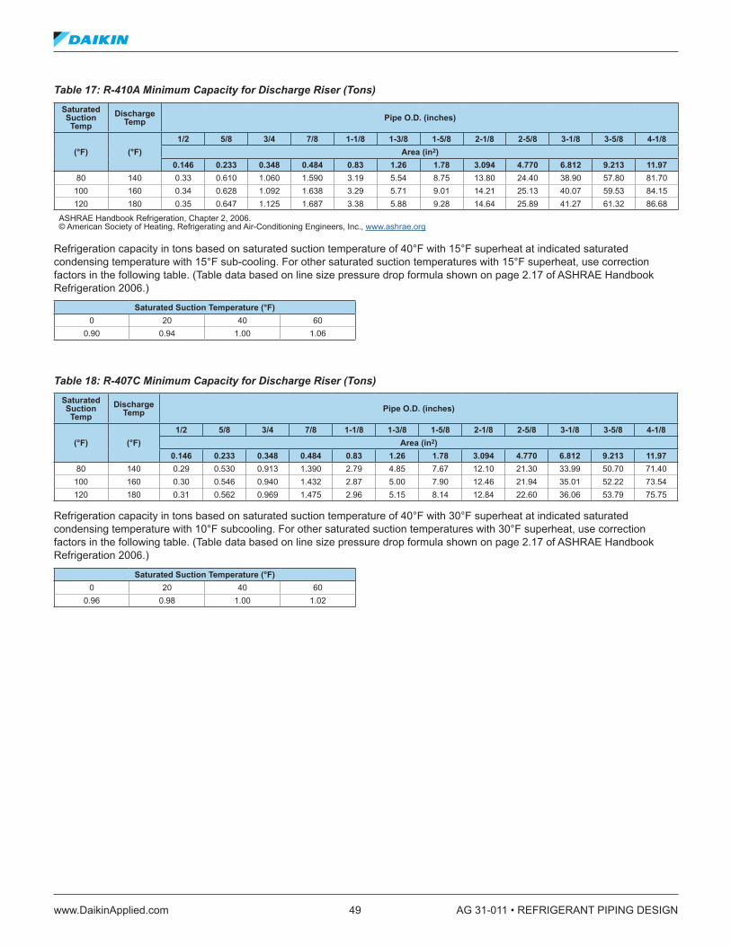
www.DaikinApplied.com 49 AG 31-011 • REFRIGERANT PIPING DESIGN
Table 17: R-410A Minimum Capacity for Discharge Riser (Tons) Saturated Suction Temp
Discharge Temp Pipe O .D . (inches)
(°F) (°F)1/2 5/8 3/4 7/8 1-1/8 1-3/8 1-5/8 2-1/8 2-5/8 3-1/8 3-5/8 4-1/8
Area (in2)0 .146 0 .233 0 .348 0 .484 0 .83 1 .26 1 .78 3 .094 4 .770 6 .812 9 .213 11 .97
80 140 0.33 0.610 1.060 1.590 3.19 5.54 8.75 13.80 24.40 38.90 57.80 81.70100 160 0.34 0.628 1.092 1.638 3.29 5.71 9.01 14.21 25.13 40.07 59.53 84.15120 180 0.35 0.647 1.125 1.687 3.38 5.88 9.28 14.64 25.89 41.27 61.32 86.68
ASHRAE Handbook Refrigeration, Chapter 2, 2006. © American Society of Heating, Refrigerating and Air-Conditioning Engineers, Inc., www.ashrae.org
Refrigeration capacity in tons based on saturated suction temperature of 40°F with 15°F superheat at indicated saturated condensing temperature with 15°F sub-cooling. For other saturated suction temperatures with 15°F superheat, use correction factors in the following table. (Table data based on line size pressure drop formula shown on page 2.17 of ASHRAE Handbook Refrigeration 2006.)
Saturated Suction Temperature (°F)0 20 40 60
0.90 0.94 1.00 1.06
Table 18: R-407C Minimum Capacity for Discharge Riser (Tons) Saturated Suction Temp
Discharge Temp Pipe O .D . (inches)
(°F) (°F)1/2 5/8 3/4 7/8 1-1/8 1-3/8 1-5/8 2-1/8 2-5/8 3-1/8 3-5/8 4-1/8
Area (in2)0 .146 0 .233 0 .348 0 .484 0 .83 1 .26 1 .78 3 .094 4 .770 6 .812 9 .213 11 .97
80 140 0.29 0.530 0.913 1.390 2.79 4.85 7.67 12.10 21.30 33.99 50.70 71.40100 160 0.30 0.546 0.940 1.432 2.87 5.00 7.90 12.46 21.94 35.01 52.22 73.54120 180 0.31 0.562 0.969 1.475 2.96 5.15 8.14 12.84 22.60 36.06 53.79 75.75
Refrigeration capacity in tons based on saturated suction temperature of 40°F with 30°F superheat at indicated saturated condensing temperature with 10°F subcooling. For other saturated suction temperatures with 30°F superheat, use correction factors in the following table. (Table data based on line size pressure drop formula shown on page 2.17 of ASHRAE Handbook Refrigeration 2006.)
Saturated Suction Temperature (°F) 0 20 40 60
0.96 0.98 1.00 1.02

AG 31-011 • REFRIGERANT PIPING DESIGN 50 www.DaikinApplied.com
Table 19: R-22 Refrigerant Charge (Lbs . per 100 Feet of Pipe)
Line Size OD Flow AreaSuction Line Liquid Line Discharge
Line40°F 105°F 140°F
inches in2 1 .52 lb ./ft3 68 .72 lb ./ft3 6 .97 lb ./ft3
1/2 0.145 0.15 6.92 0.705/8 0.233 0.25 11.12 1.137/8 0.484 0.51 23.10 2.34
1-1/8 0.825 0.87 39.37 3.991-3/8 1.257 1.33 59.99 6.081-5/8 1.779 1.88 84.90 8.612-1/8 3.905 4.13 186.36 18.902-5/8 4.772 5.04 227.73 23.093-1/8 6.812 7.20 325.08 32.973-5/8 9.213 9.74 439.66 44.584-1/8 11.977 12.66 571.57 57.965-1/8 18.665 19.72 890.74 90.336-1/8 26.832 28.35 1280.48 129.858-1/8 46.869 49.53 2236.69 226.81
Refrigerant weight per 100 feet of pipe is based on 105°F condensing temperature and 10°F sub-cooling, 140°F discharge temperature, and 40°F saturated suction temperature.
Table 20: R-134a Refrigerant Charge (Lbs . per 100 feet of Pipe)
Line Size OD Flow AreaSuction Line Liquid Line Discharge
Line40°F 105°F 140°F
inches in2 1 .05 lb ./ft3 69 .93 lb ./ft3 5 .46 lb ./ft3
1/2 0.145 0.11 7.04 0.555/8 0.233 0.17 11.32 0.887/8 0.484 0.35 23.50 1.83
1-1/8 0.825 0.60 40.06 3.131-3/8 1.257 0.92 61.04 4.761-5/8 1.779 1.30 86.39 6.742-1/8 3.905 2.85 189.64 14.792-5/8 4.772 3.48 231.74 18.083-1/8 6.812 4.96 330.81 25.813-5/8 9.213 6.71 447.41 34.904-1/8 11.977 8.73 581.63 45.385-1/8 18.665 13.60 906.42 70.716-1/8 26.832 19.56 1303.03 101.658-1/8 46.869 34.16 2276.08 177.57
Refrigerant weight per 100 feet of pipe is based on 105°F condensing temperature and 10°F sub-cooling, 140°F discharge temperature, and 40°F saturated suction temperature.
Table 21: R-410A Refrigerant Charge (Lbs . per 100 feet of Pipe)
Line Size OD Flow AreaSuction Line Liquid Line Discharge
Line40°F 105°F 140°F
inches in2 2 .21 lb ./ft3 58 .37 lb ./ft3 12 .57 lb ./ft3
1/2 0.145 0.22 5.88 1.275/8 0.233 0.36 9.44 2.037/8 0.484 0.74 19.62 4.22
1-1/8 0.825 1.26 33.44 7.201-3/8 1.257 1.93 50.95 10.971-5/8 1.779 2.72 72.11 15.532-1/8 3.905 5.98 158.29 34.092-5/8 4.772 7.31 193.43 41.663-1/8 6.812 10.43 276.12 59.463-5/8 9.213 14.11 373.45 80.424-1/8 11.977 18.34 485.48 104.555-1/8 18.665 28.59 756.58 162.936-1/8 26.832 41.10 1087.63 234.228-1/8 46.869 71.79 1899.82 409.12
Refrigerant weight per 100 feet of pipe is based on 105°F condensing temperature and 10°F sub-cooling, 140°F discharge temperature, and 40°F saturated suction temperature.
Table 22: R-407C Refrigerant Charge (lbs . Per 100 Feet of Pipe)
Line Size OD Flow AreaSuction Line Liquid Line Discharge
Line40°F 105°F 140°F
inches in2 1 .69 lb ./ft3 64 .65 lb ./ft3 8 .64 lb ./ft3
1/2 0.145 0.17 6.51 0.875/8 0.233 0.27 10.46 1.407/8 0.484 0.57 21.73 2.91
1-1/8 0.825 0.97 37.04 4.951-3/8 1.257 1.48 56.43 7.551-5/8 1.779 2.09 79.87 10.682-1/8 3.905 4.59 175.32 23.442-5/8 4.772 5.61 214.24 28.653-1/8 6.812 8.01 305.83 40.893-5/8 9.213 10.83 413.63 55.304-1/8 11.977 14.09 537.72 71.905-1/8 18.665 21.95 837.98 112.046-1/8 26.832 31.56 1204.65 161.078-1/8 46.869 55.12 2104.22 281.34
Refrigerant weight per 100 feet of pipe is based on 105°F condensing temperature and 10°F sub-cooling, 140°F discharge temperature, and 40°F saturated suction temperature.
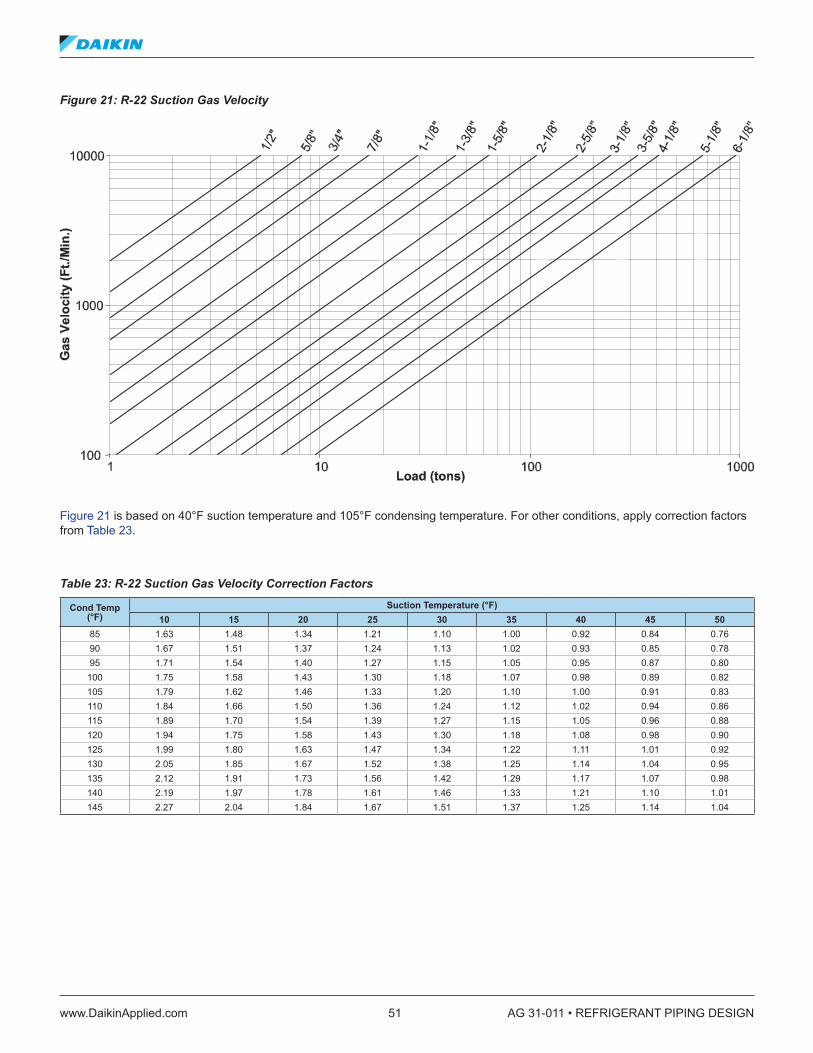
www.DaikinApplied.com 51 AG 31-011 • REFRIGERANT PIPING DESIGN
Figure 21: R-22 Suction Gas Velocity
Figure 21 is based on 40°F suction temperature and 105°F condensing temperature. For other conditions, apply correction factors from Table 23.
Table 23: R-22 Suction Gas Velocity Correction Factors
Cond Temp (°F)
Suction Temperature (°F)10 15 20 25 30 35 40 45 50
85 1.63 1.48 1.34 1.21 1.10 1.00 0.92 0.84 0.7690 1.67 1.51 1.37 1.24 1.13 1.02 0.93 0.85 0.7895 1.71 1.54 1.40 1.27 1.15 1.05 0.95 0.87 0.80
100 1.75 1.58 1.43 1.30 1.18 1.07 0.98 0.89 0.82105 1.79 1.62 1.46 1.33 1.20 1.10 1.00 0.91 0.83110 1.84 1.66 1.50 1.36 1.24 1.12 1.02 0.94 0.86115 1.89 1.70 1.54 1.39 1.27 1.15 1.05 0.96 0.88120 1.94 1.75 1.58 1.43 1.30 1.18 1.08 0.98 0.90125 1.99 1.80 1.63 1.47 1.34 1.22 1.11 1.01 0.92130 2.05 1.85 1.67 1.52 1.38 1.25 1.14 1.04 0.95135 2.12 1.91 1.73 1.56 1.42 1.29 1.17 1.07 0.98140 2.19 1.97 1.78 1.61 1.46 1.33 1.21 1.10 1.01145 2.27 2.04 1.84 1.67 1.51 1.37 1.25 1.14 1.04

AG 31-011 • REFRIGERANT PIPING DESIGN 52 www.DaikinApplied.com
Figure 22: R-134a Suction Gas Velocity
Figure 22 is based on 40°F suction temperature and 105°F condensing temperature. For other conditions, apply correction factors from Table 24.
Table 24: R-134a Suction Gas Velocity Correction Factors
Cond Temp (°F)
Suction Temperature (°F)10 15 20 25 30 35 40 45 50
85 1.76 1.56 1.40 1.25 1.12 1.00 0.90 0.82 0.7490 1.81 1.61 1.43 1.28 1.15 1.03 0.93 0.84 0.7695 1.86 1.65 1.47 1.32 1.18 1.06 0.95 0.86 0.77
100 1.91 1.70 1.52 1.35 1.21 1.09 0.98 0.88 0.80105 1.97 1.75 1.56 1.39 1.25 1.12 1.00 0.91 0.82110 2.04 1.81 1.61 1.44 1.29 1.15 1.04 0.93 0.84115 2.10 1.87 1.66 1.48 1.33 1.19 1.07 0.96 0.87120 2.18 1.93 1.72 1.53 1.37 1.23 1.10 0.99 0.90125 2.26 2.00 1.78 1.59 1.42 1.27 1.14 1.03 0.92130 2.35 2.08 1.85 1.65 1.47 1.32 1.18 1.06 0.96135 2.44 2.16 1.92 1.71 1.53 1.37 1.23 1.10 0.99140 2.55 2.26 2.00 1.78 1.59 1.42 1.27 1.14 1.03145 2.66 2.36 2.09 1.86 1.66 1.48 1.33 1.19 1.07
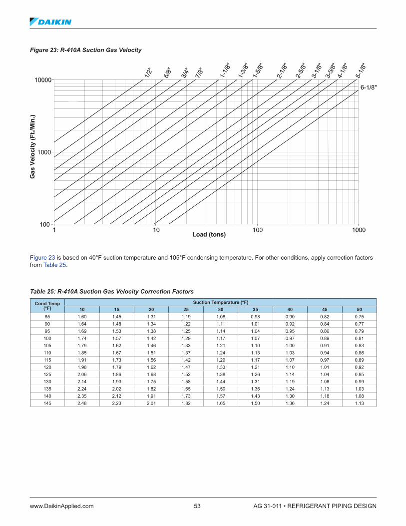
www.DaikinApplied.com 53 AG 31-011 • REFRIGERANT PIPING DESIGN
Figure 23: R-410A Suction Gas Velocity
Figure 23 is based on 40°F suction temperature and 105°F condensing temperature. For other conditions, apply correction factors from Table 25.
Table 25: R-410A Suction Gas Velocity Correction Factors
Cond Temp (°F)
Suction Temperature (°F)10 15 20 25 30 35 40 45 50
85 1.60 1.45 1.31 1.19 1.08 0.98 0.90 0.82 0.7590 1.64 1.48 1.34 1.22 1.11 1.01 0.92 0.84 0.7795 1.69 1.53 1.38 1.25 1.14 1.04 0.95 0.86 0.79
100 1.74 1.57 1.42 1.29 1.17 1.07 0.97 0.89 0.81105 1.79 1.62 1.46 1.33 1.21 1.10 1.00 0.91 0.83110 1.85 1.67 1.51 1.37 1.24 1.13 1.03 0.94 0.86115 1.91 1.73 1.56 1.42 1.29 1.17 1.07 0.97 0.89120 1.98 1.79 1.62 1.47 1.33 1.21 1.10 1.01 0.92125 2.06 1.86 1.68 1.52 1.38 1.26 1.14 1.04 0.95130 2.14 1.93 1.75 1.58 1.44 1.31 1.19 1.08 0.99135 2.24 2.02 1.82 1.65 1.50 1.36 1.24 1.13 1.03140 2.35 2.12 1.91 1.73 1.57 1.43 1.30 1.18 1.08145 2.48 2.23 2.01 1.82 1.65 1.50 1.36 1.24 1.13
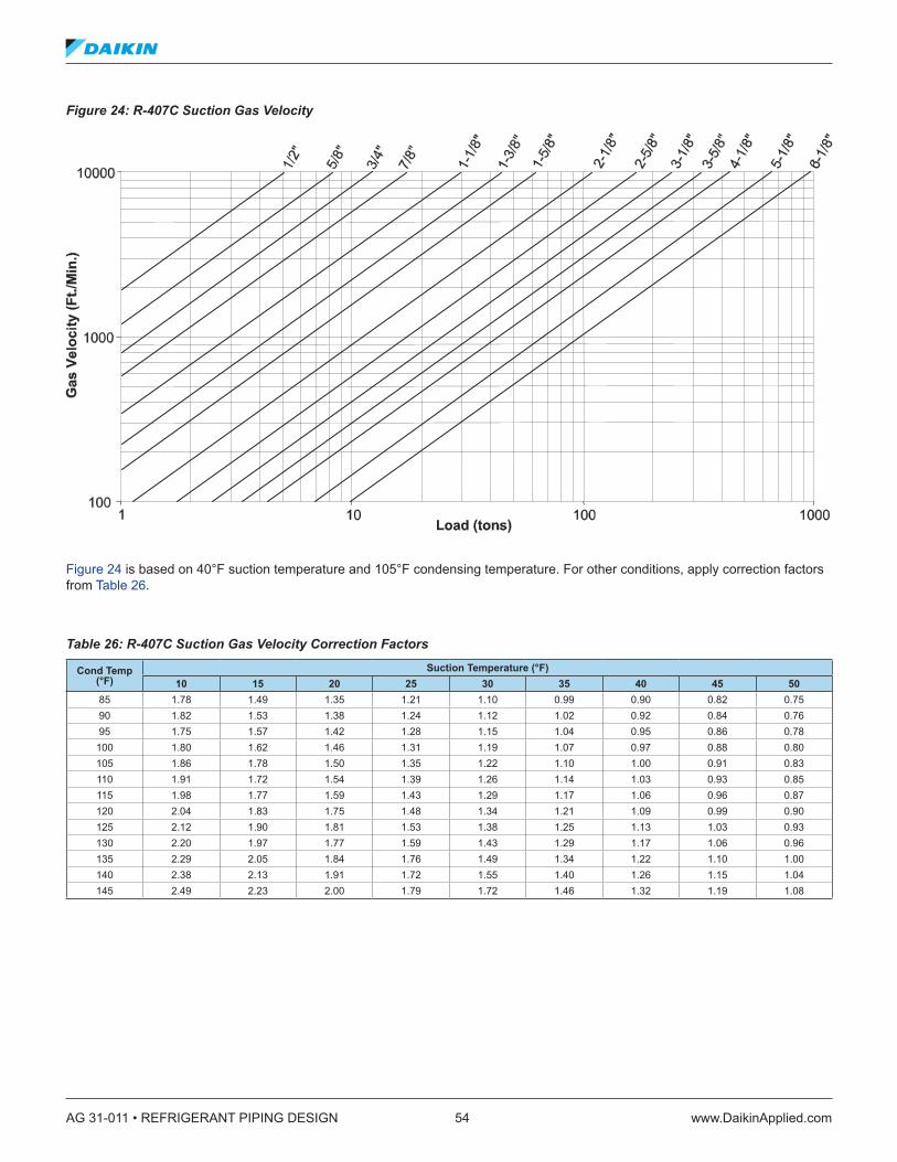
AG 31-011 • REFRIGERANT PIPING DESIGN 54 www.DaikinApplied.com
Figure 24: R-407C Suction Gas Velocity
Figure 24 is based on 40°F suction temperature and 105°F condensing temperature. For other conditions, apply correction factors from Table 26.
Table 26: R-407C Suction Gas Velocity Correction Factors
Cond Temp (°F)
Suction Temperature (°F)10 15 20 25 30 35 40 45 50
85 1.78 1.49 1.35 1.21 1.10 0.99 0.90 0.82 0.7590 1.82 1.53 1.38 1.24 1.12 1.02 0.92 0.84 0.7695 1.75 1.57 1.42 1.28 1.15 1.04 0.95 0.86 0.78
100 1.80 1.62 1.46 1.31 1.19 1.07 0.97 0.88 0.80105 1.86 1.78 1.50 1.35 1.22 1.10 1.00 0.91 0.83110 1.91 1.72 1.54 1.39 1.26 1.14 1.03 0.93 0.85115 1.98 1.77 1.59 1.43 1.29 1.17 1.06 0.96 0.87120 2.04 1.83 1.75 1.48 1.34 1.21 1.09 0.99 0.90125 2.12 1.90 1.81 1.53 1.38 1.25 1.13 1.03 0.93130 2.20 1.97 1.77 1.59 1.43 1.29 1.17 1.06 0.96135 2.29 2.05 1.84 1.76 1.49 1.34 1.22 1.10 1.00140 2.38 2.13 1.91 1.72 1.55 1.40 1.26 1.15 1.04145 2.49 2.23 2.00 1.79 1.72 1.46 1.32 1.19 1.08

www.DaikinApplied.com 55 AG 31-011 • REFRIGERANT PIPING DESIGN
Figure 25: R-22 Discharge Gas Velocity
Figure 25 is based on 40°F suction temperature and 105°F condensing temperature. For other conditions, apply correction factors from Table 27.
Table 27: R-22 Discharge Gas Velocity Correction Factors
Cond Temp (°F)
Suction Temperature (°F)150 160 170 180 190 200 210 220 230
85 1.20 1.23 1.26 1.28 1.31 1.34 1.37 1.39 1.4290 1.12 1.15 1.17 1.20 1.23 1.26 1.28 1.31 1.3395 1.05 1.08 1.10 1.13 1.16 1.18 1.21 1.23 1.26
100 0.98 1.01 1.04 1.06 1.09 1.11 1.14 1.16 1.19105 0.92 0.95 0.97 1.00 1.03 1.05 1.07 1.10 1.12110 0.86 0.89 0.92 0.94 0.97 0.99 1.01 1.04 1.06115 0.81 0.84 0.86 0.89 0.91 0.93 0.96 0.98 1.01120 0.76 0.79 0.81 0.84 0.86 0.88 0.91 0.93 0.96125 0.72 0.74 0.76 0.79 0.81 0.84 0.86 0.88 0.91130 0.67 0.70 0.72 0.74 0.77 0.79 0.82 0.84 0.87135 0.63 0.65 0.68 0.70 0.73 0.75 0.78 0.80 0.82140 0.59 0.62 0.64 0.67 0.69 0.72 0.74 0.77 0.79145 0.55 0.58 0.60 0.63 0.66 0.68 0.71 0.73 0.76

AG 31-011 • REFRIGERANT PIPING DESIGN 56 www.DaikinApplied.com
Figure 26: R-134a Discharge Gas Velocity
Figure 26 is based on 40°F suction temperature and 105°F condensing temperature. For other conditions, apply correction factors from Table 28.
Table 28: R-134a Suction Gas Velocity Correction Factors
Cond Temp (°F)
Suction Temperature (°F)150 160 170 180 190 200 210 220 230
85 1.23 1.26 1.29 1.32 1.35 1.37 1.40 1.43 1.4690 1.15 1.17 1.20 1.23 1.26 1.28 1.31 1.34 1.3695 1.07 1.09 1.12 1.14 1.17 1.19 1.22 1.25 1.27
100 0.99 1.02 1.04 1.07 1.09 1.12 1.14 1.17 1.19105 0.92 0.95 0.97 1.00 1.02 1.04 1.07 1.09 1.12110 0.86 0.88 0.91 0.93 0.95 0.98 1.00 1.02 1.05115 0.80 0.83 0.85 0.87 0.89 0.92 0.94 0.96 0.99120 0.75 0.77 0.79 0.82 0.84 0.86 0.88 0.91 0.93125 0.70 0.72 0.75 0.77 0.79 0.81 0.83 0.86 0.88130 0.65 0.68 0.70 0.72 0.74 0.76 0.79 0.81 0.83135 0.61 0.63 0.65 0.68 0.70 0.72 0.74 0.76 0.79140 0.57 0.59 0.61 0.64 0.66 0.68 0.70 0.72 0.75145 0.53 0.55 0.57 0.60 0.62 0.64 0.66 0.69 0.71

www.DaikinApplied.com 57 AG 31-011 • REFRIGERANT PIPING DESIGN
Figure 27: R-410A Discharge Gas Velocity
Figure 27 is based on 40°F suction temperature and 105°F condensing temperature. For other conditions, apply correction factors from Table 29.
Table 29: R-410A Suction Gas Velocity Correction Factors
Cond Temp (°F)
Suction Temperature (°F)150 160 170 180 190 200 210 220 230
85 1.13 1.17 1.20 1.23 1.26 1.29 1.32 1.35 1.3990 1.07 1.10 1.13 1.16 1.19 1.22 1.25 1.29 1.3295 1.01 1.04 1.07 1.10 1.13 1.16 1.19 1.22 1.25
100 0.95 0.98 1.01 1.04 1.07 1.10 1.13 1.17 1.20105 0.90 0.93 0.96 0.99 1.02 1.05 1.08 1.11 1.15110 0.85 0.88 0.91 0.95 0.98 1.01 1.04 1.07 1.10115 0.81 0.84 0.87 0.91 0.94 0.97 1.00 1.03 1.06120 0.77 0.80 0.84 0.87 0.90 0.93 0.97 1.00 1.03125 0.73 0.77 0.80 0.84 0.87 0.91 0.94 0.97 1.01130 0.70 0.74 0.77 0.81 0.85 0.88 0.92 0.96 0.99135 0.67 0.71 0.75 0.79 0.83 0.87 0.91 0.95 0.99140 0.64 0.69 0.73 0.78 0.82 0.86 0.91 0.95 1.00145 0.61 0.67 0.72 0.77 0.82 0.87 0.93 0.98 1.03
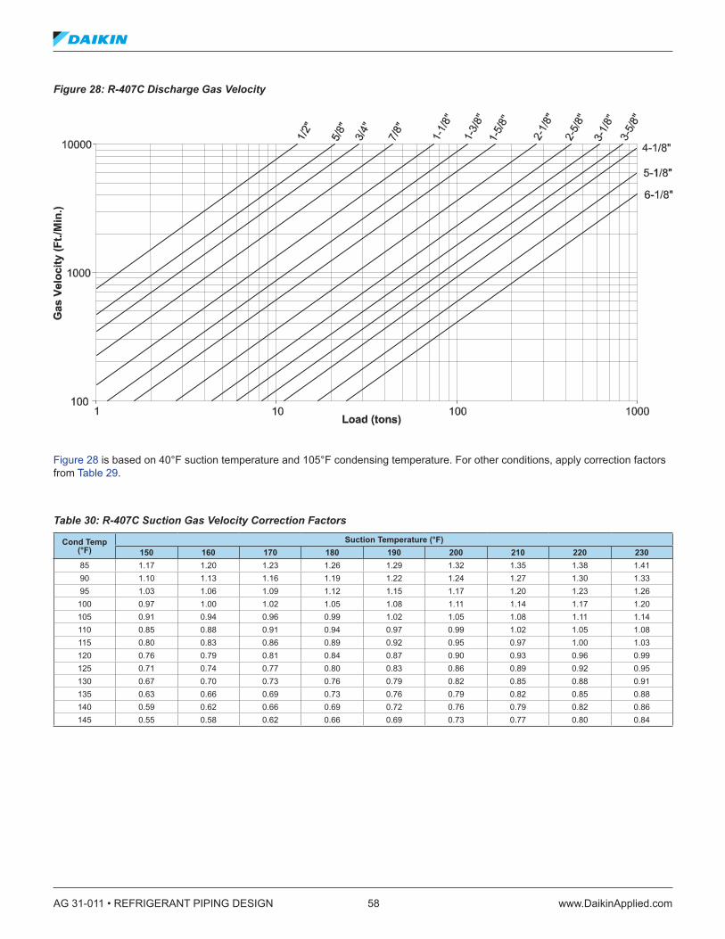
AG 31-011 • REFRIGERANT PIPING DESIGN 58 www.DaikinApplied.com
Figure 28: R-407C Discharge Gas Velocity
Figure 28 is based on 40°F suction temperature and 105°F condensing temperature. For other conditions, apply correction factors from Table 29.
Table 30: R-407C Suction Gas Velocity Correction Factors
Cond Temp (°F)
Suction Temperature (°F)150 160 170 180 190 200 210 220 230
85 1.17 1.20 1.23 1.26 1.29 1.32 1.35 1.38 1.4190 1.10 1.13 1.16 1.19 1.22 1.24 1.27 1.30 1.3395 1.03 1.06 1.09 1.12 1.15 1.17 1.20 1.23 1.26
100 0.97 1.00 1.02 1.05 1.08 1.11 1.14 1.17 1.20105 0.91 0.94 0.96 0.99 1.02 1.05 1.08 1.11 1.14110 0.85 0.88 0.91 0.94 0.97 0.99 1.02 1.05 1.08115 0.80 0.83 0.86 0.89 0.92 0.95 0.97 1.00 1.03120 0.76 0.79 0.81 0.84 0.87 0.90 0.93 0.96 0.99125 0.71 0.74 0.77 0.80 0.83 0.86 0.89 0.92 0.95130 0.67 0.70 0.73 0.76 0.79 0.82 0.85 0.88 0.91135 0.63 0.66 0.69 0.73 0.76 0.79 0.82 0.85 0.88140 0.59 0.62 0.66 0.69 0.72 0.76 0.79 0.82 0.86145 0.55 0.58 0.62 0.66 0.69 0.73 0.77 0.80 0.84

www.DaikinApplied.com 59 AG 31-011 • REFRIGERANT PIPING DESIGN
Appendix 3 – Refrigerant Piping Tables (SI Units)Table 31: Copper Tube Data – SI
Nominal Diameter Type
Wall Diameter Diameter Surface
AreaCross
Section Weight Working Pressure ASTM B88 To 120°C
(mm) Outside D, (mm)
Insided (mm)
Outside (m²/m)
Inside (m²/m)
Metal Area (mm²)
Flow Area (mm²)
Tube (kg/m)
Annealed (MPa)
Drawn (MPa)
12K 1.24 12.70 10.21 0.040 0.0320 45 82 0.400 6.164 11.556L 0.89 12.70 10.92 0.040 0.0344 33 94 0.295 4.399 8.253
15K 1.24 15.88 13.39 0.050 0.0421 57 141 0.512 4.930 9.246L 1.02 15.88 13.84 0.050 0.0436 48 151 0.424 4.027 7.543
18K 1.24 19.05 16.56 0.060 0.0521 70 215 0.622 4.109 7.702L 1.07 19.05 16.92 0.060 0.0530 60 225 0.539 3.523 6.605
22K 1.65 22.23 18.92 0.070 0.0594 106 281 0.954 4.668 8.757L 1.14 22.23 19.94 0.070 0.0628 75 312 0.677 3.234 6.061
28K 1.65 28.58 25.27 0.090 0.0792 139 502 1.249 3.634 6.812L 1.27 28.58 26.04 0.090 0.0817 109 532 0.973 2.792 5.240
35K 1.65 34.93 31.62 0.110 0.0994 173 785 1.543 2.972 5.571L 1.40 34.93 32.13 0.110 0.1009 147 811 1.316 2.517 4.716
42K 1.83 41.28 37.62 0.130 0.1183 226 1111 2.025 2.786 5.226L 1.52 41.28 38.23 0.130 0.1201 190 1148 1.701 2.324 4.351
54K 2.11 53.98 49.76 0.170 0.1564 343 1945 3.070 2.455 4.606L 1.78 53.98 50.42 0.170 0.1585 292 1997 2.606 2.069 3.951
67K 2.41 66.68 61.85 0.209 .01942 487 3004 4.35 2.275 4.268L 2.03 66.68 62.61 0.209 0.1966 413 3079 3.69 1.917 3.592
79K 2.77 79.38 73.84 0.249 0.2320 666 4282 5.96 2.193 4.109L 2.29 79.38 74.80 0.249 0.2350 554 4395 4.95 1.813 3.392
92K 3.05 92.08 85.98 0.289 0.2701 852 5806 7.62 2.082 3.903L 2.54 92.08 87.00 0.289 0.2733 714 5944 6.39 1.738 3.254
105K 3.40 104.78 97.97 0.329 0.3078 1084 7538 9.69 2.041 3.827L 2.79 107.78 99.19 0.329 0.3115 895 7727 8.00 1.675 3.144
130K 4.06 130.18 122.05 0.409 0.3834 1610 11699 14.39 1.965 3.682L 3.18 130.18 123.83 0.409 0.3889 1266 12042 11.32 1.531 2.875
156K 4.88 155.58 145.82 0.489 0.4581 2309 16701 20.64 1.972 3.696L 3.56 155.58 148.46 0.489 0.4663 1698 17311 15.18 1.434 2.696
206K 6.88 206.38 192.61 0.648 0.6050 4314 29137 38.56 2.096 3.930L 5.08 206.38 196.22 0.648 0.6163 3212 30238 28.71 1.544 2.903
ASHRAE Handbook HVAC Systems And Equipment, Chapter 41, 2004. © American Society of Heating, Refrigerating and Air-Conditioning Engineers, Inc., www.ashrae.org

AG 31-011 • REFRIGERANT PIPING DESIGN 60 www.DaikinApplied.com
Table 32: Equivalent Length for Fittings – SI
Nominal Diameter
Smooth Elbows Smooth Bend Tee Connections
90° Std 90° Long Radius 90° Street 45° Std 45° Street 180° Std Tee Branch
FlowStraight Through Flow
No Reduction
Reduced 25%
Reduced 50%
12 0.4 0.3 0.7 0.2 0.3 0.7 0.8 0.3 0.4 0.415 0.5 0.3 0.8 0.2 0.4 0.8 0.9 0.3 0.4 0.522 0.6 0.4 1.0 0.3 0.5 1.0 1.2 0.4 0.6 0.628 0.8 0.5 1.2 0.4 0.6 1.2 1.5 0.5 0.7 0.835 1.0 0.7 1.7 0.5 0.9 1.7 2.1 0.7 0.9 1.042 1.2 0.8 1.9 0.6 1.0 1.9 2.4 0.8 1.1 1.254 1.5 1.0 2.5 0.8 1.4 2.5 3.0 1.0 1.4 1.567 1.8 1.2 3.0 1.0 1.6 3.0 3.7 1.2 1.7 1.879 2.3 1.5 3.7 1.2 2.0 3.7 4.6 1.5 2.1 2.390 2.7 1.8 4.6 1.4 2.2 4.6 5.5 1.8 2.4 2.7
105 3.0 2.0 5.2 1.6 2.6 5.2 6.4 2.0 2.7 3.0130 4.0 2.5 6.4 2.0 3.4 6.4 7.6 2.5 3.7 4.0156 4.9 3.0 7.6 2.4 4.0 7.6 9 3.0 4.3 4.9206 6.1 4.0 — 3.0 — 10 12 4.0 5.5 6.1257 7.6 4.9 — 4.0 — 13 15 4.9 7.0 7.6300 9.1 5.8 — 4.9 — 15 18 5.8 7.9 9.1
ASHRAE Handbook Refrigeration, Chapter 2, 2006. © American Society of Heating, Refrigerating and Air-Conditioning Engineers, Inc., www.ashrae.org
Table 33: Equivalent Length for Valves and Refrigeration Devices – SI Nominal Diameter
Globe or Solenoid
60° Wye Valve
45° Wye Valve Angle Valve Gate Valve Swing Check Sight Glass Filter-Drier Suction Filter
12 5.2 2.4 1.8 1.8 0.2 1.5 — — —15 5.5 2.7 2.1 2.1 0.2 1.8 — — —22 6.7 3.4 2.1 2.1 0.3 2.2 — — —28 8.8 4.6 3.7 3.7 0.3 3.0 — — —35 12 6.1 4.6 4.6 0.5 4.3 — — —42 13 7.3 5.5 5.5 0.5 4.9 — — —54 17 9.1 7.3 7.3 0.73 6.1 — — —67 21 11 8.8 8.8 0.9 7.6 — — —79 26 13 11 11 1.0 9.1 — — —90 30 15 13 13 1.2 10 — — —
105 37 18 14 14 1.4 12 — — —130 43 22 18 18 1.8 15 — — —156 52 27 21 21 2.1 18 — — —206 62 35 26 26 2.7 24 — — —257 85 44 32 32 3.7 30 — — —300 98 50 40 40 4.0 37 — — —
ASHRAE Handbook Refrigeration, Chapter 2, 2006. © American Society of Heating, Refrigerating and Air-Conditioning Engineers, Inc., www.ashrae.org
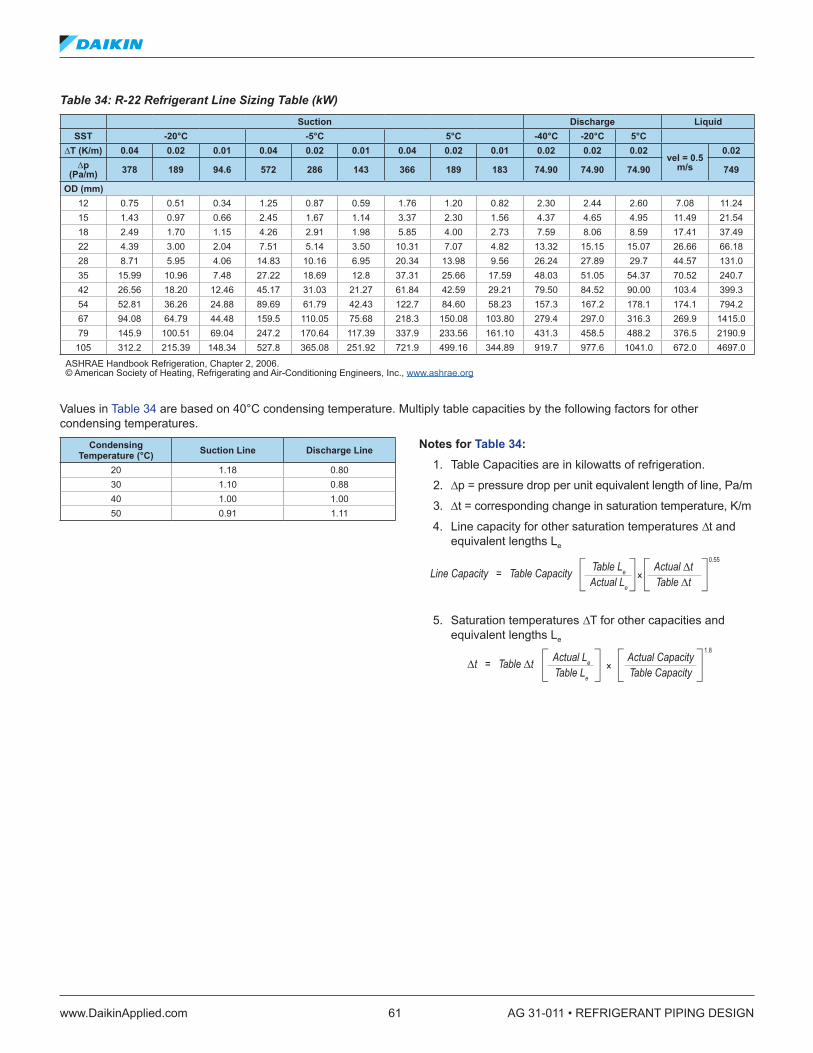
www.DaikinApplied.com 61 AG 31-011 • REFRIGERANT PIPING DESIGN
Table 34: R-22 Refrigerant Line Sizing Table (kW)Suction Discharge Liquid
SST -20°C -5°C 5°C -40°C -20°C 5°C∆T (K/m) 0 .04 0 .02 0 .01 0 .04 0 .02 0 .01 0 .04 0 .02 0 .01 0 .02 0 .02 0 .02
vel = 0 .5 m/s
0 .02∆p
(Pa/m) 378 189 94 .6 572 286 143 366 189 183 74 .90 74 .90 74 .90 749
OD (mm)12 0.75 0.51 0.34 1.25 0.87 0.59 1.76 1.20 0.82 2.30 2.44 2.60 7.08 11.2415 1.43 0.97 0.66 2.45 1.67 1.14 3.37 2.30 1.56 4.37 4.65 4.95 11.49 21.5418 2.49 1.70 1.15 4.26 2.91 1.98 5.85 4.00 2.73 7.59 8.06 8.59 17.41 37.4922 4.39 3.00 2.04 7.51 5.14 3.50 10.31 7.07 4.82 13.32 15.15 15.07 26.66 66.1828 8.71 5.95 4.06 14.83 10.16 6.95 20.34 13.98 9.56 26.24 27.89 29.7 44.57 131.035 15.99 10.96 7.48 27.22 18.69 12.8 37.31 25.66 17.59 48.03 51.05 54.37 70.52 240.742 26.56 18.20 12.46 45.17 31.03 21.27 61.84 42.59 29.21 79.50 84.52 90.00 103.4 399.354 52.81 36.26 24.88 89.69 61.79 42.43 122.7 84.60 58.23 157.3 167.2 178.1 174.1 794.267 94.08 64.79 44.48 159.5 110.05 75.68 218.3 150.08 103.80 279.4 297.0 316.3 269.9 1415.079 145.9 100.51 69.04 247.2 170.64 117.39 337.9 233.56 161.10 431.3 458.5 488.2 376.5 2190.9
105 312.2 215.39 148.34 527.8 365.08 251.92 721.9 499.16 344.89 919.7 977.6 1041.0 672.0 4697.0
ASHRAE Handbook Refrigeration, Chapter 2, 2006. © American Society of Heating, Refrigerating and Air-Conditioning Engineers, Inc., www.ashrae.org
Values in Table 34 are based on 40°C condensing temperature. Multiply table capacities by the following factors for other condensing temperatures.
Condensing Temperature (°C) Suction Line Discharge Line
20 1.18 0.8030 1.10 0.8840 1.00 1.0050 0.91 1.11
Notes for Table 34: 1. Table Capacities are in kilowatts of refrigeration.
2. ∆p = pressure drop per unit equivalent length of line, Pa/m
3. ∆t = corresponding change in saturation temperature, K/m
4. Line capacity for other saturation temperatures ∆t and equivalent lengths Le
5. Saturation temperatures ∆T for other capacities and equivalent lengths Le
Line Capacity = Table Capacity Table Le
Actual Le
Actual ∆tTable ∆t
0.55
R-22 Sizing — Notes
×
∆t = Table ∆t Actual Le
Table Le
Actual CapacityTable Capacity
1.8
×
Line Capacity = Table Capacity Table Le
Actual Le
Actual ∆tTable ∆t
0.55
R-22 Sizing — Notes
×
∆t = Table ∆t Actual Le
Table Le
Actual CapacityTable Capacity
1.8
×
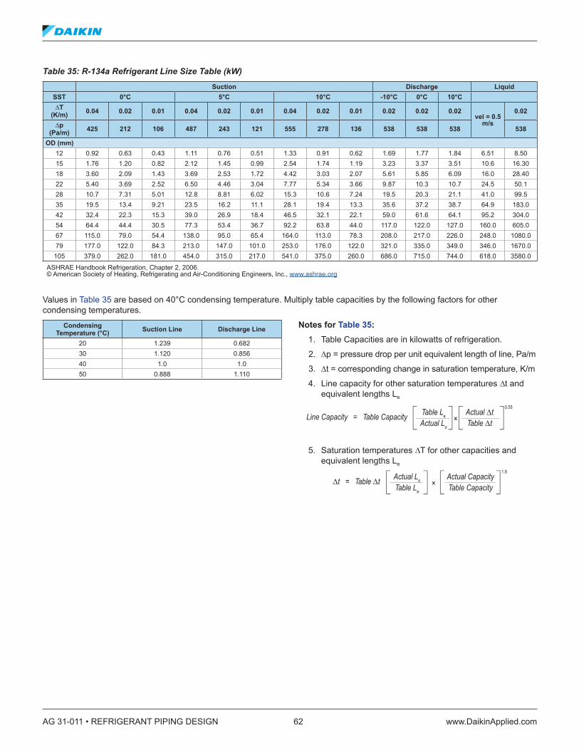
AG 31-011 • REFRIGERANT PIPING DESIGN 62 www.DaikinApplied.com
Table 35: R-134a Refrigerant Line Size Table (kW)Suction Discharge Liquid
SST 0°C 5°C 10°C -10°C 0°C 10°C∆T
(K/m) 0 .04 0 .02 0 .01 0 .04 0 .02 0 .01 0 .04 0 .02 0 .01 0 .02 0 .02 0 .02vel = 0 .5
m/s
0 .02
∆p (Pa/m) 425 212 106 487 243 121 555 278 136 538 538 538 538
OD (mm)12 0.92 0.63 0.43 1.11 0.76 0.51 1.33 0.91 0.62 1.69 1.77 1.84 6.51 8.5015 1.76 1.20 0.82 2.12 1.45 0.99 2.54 1.74 1.19 3.23 3.37 3.51 10.6 16.3018 3.60 2.09 1.43 3.69 2.53 1.72 4.42 3.03 2.07 5.61 5.85 6.09 16.0 28.4022 5.40 3.69 2.52 6.50 4.46 3.04 7.77 5.34 3.66 9.87 10.3 10.7 24.5 50.128 10.7 7.31 5.01 12.8 8.81 6.02 15.3 10.6 7.24 19.5 20.3 21.1 41.0 99.535 19.5 13.4 9.21 23.5 16.2 11.1 28.1 19.4 13.3 35.6 37.2 38.7 64.9 183.042 32.4 22.3 15.3 39.0 26.9 18.4 46.5 32.1 22.1 59.0 61.6 64.1 95.2 304.054 64.4 44.4 30.5 77.3 53.4 36.7 92.2 63.8 44.0 117.0 122.0 127.0 160.0 605.067 115.0 79.0 54.4 138.0 95.0 65.4 164.0 113.0 78.3 208.0 217.0 226.0 248.0 1080.079 177.0 122.0 84.3 213.0 147.0 101.0 253.0 176.0 122.0 321.0 335.0 349.0 346.0 1670.0
105 379.0 262.0 181.0 454.0 315.0 217.0 541.0 375.0 260.0 686.0 715.0 744.0 618.0 3580.0
ASHRAE Handbook Refrigeration, Chapter 2, 2006. © American Society of Heating, Refrigerating and Air-Conditioning Engineers, Inc., www.ashrae.org
Values in Table 35 are based on 40°C condensing temperature. Multiply table capacities by the following factors for other condensing temperatures.
Condensing Temperature (°C) Suction Line Discharge Line
20 1.239 0.68230 1.120 0.85640 1.0 1.050 0.888 1.110
Notes for Table 35: 1. Table Capacities are in kilowatts of refrigeration.
2. ∆p = pressure drop per unit equivalent length of line, Pa/m
3. ∆t = corresponding change in saturation temperature, K/m
4. Line capacity for other saturation temperatures ∆t and equivalent lengths Le
5. Saturation temperatures ∆T for other capacities and equivalent lengths Le
Line Capacity = Table Capacity Table Le
Actual Le
Actual ∆tTable ∆t
0.55
R-22 Sizing — Notes
×
∆t = Table ∆t Actual Le
Table Le
Actual CapacityTable Capacity
1.8
×
Line Capacity = Table Capacity Table Le
Actual Le
Actual ∆tTable ∆t
0.55
R-22 Sizing — Notes
×
∆t = Table ∆t Actual Le
Table Le
Actual CapacityTable Capacity
1.8
×
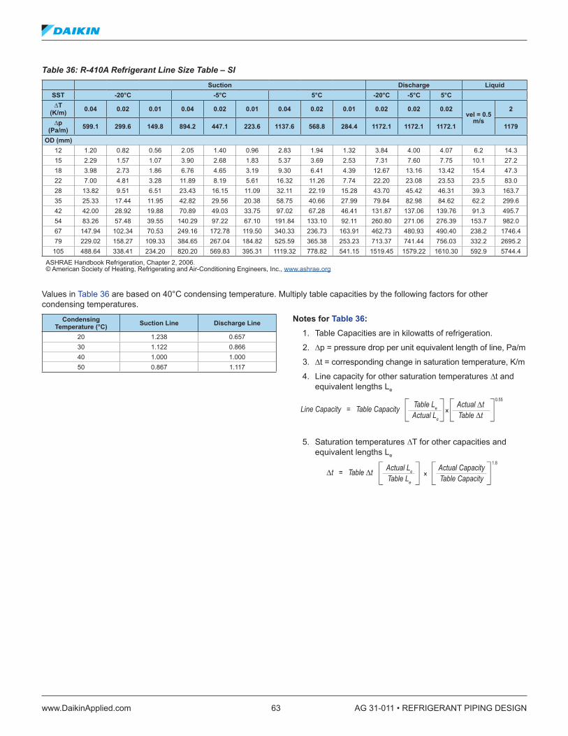
www.DaikinApplied.com 63 AG 31-011 • REFRIGERANT PIPING DESIGN
Table 36: R-410A Refrigerant Line Size Table – SI Suction Discharge Liquid
SST -20°C -5°C 5°C -20°C -5°C 5°C∆T
(K/m) 0 .04 0 .02 0 .01 0 .04 0 .02 0 .01 0 .04 0 .02 0 .01 0 .02 0 .02 0 .02vel = 0 .5
m/s
2
∆p (Pa/m) 599 .1 299 .6 149 .8 894 .2 447 .1 223 .6 1137 .6 568 .8 284 .4 1172 .1 1172 .1 1172 .1 1179
OD (mm)12 1.20 0.82 0.56 2.05 1.40 0.96 2.83 1.94 1.32 3.84 4.00 4.07 6.2 14.315 2.29 1.57 1.07 3.90 2.68 1.83 5.37 3.69 2.53 7.31 7.60 7.75 10.1 27.218 3.98 2.73 1.86 6.76 4.65 3.19 9.30 6.41 4.39 12.67 13.16 13.42 15.4 47.322 7.00 4.81 3.28 11.89 8.19 5.61 16.32 11.26 7.74 22.20 23.08 23.53 23.5 83.028 13.82 9.51 6.51 23.43 16.15 11.09 32.11 22.19 15.28 43.70 45.42 46.31 39.3 163.735 25.33 17.44 11.95 42.82 29.56 20.38 58.75 40.66 27.99 79.84 82.98 84.62 62.2 299.642 42.00 28.92 19.88 70.89 49.03 33.75 97.02 67.28 46.41 131.87 137.06 139.76 91.3 495.754 83.26 57.48 39.55 140.29 97.22 67.10 191.84 133.10 92.11 260.80 271.06 276.39 153.7 982.067 147.94 102.34 70.53 249.16 172.78 119.50 340.33 236.73 163.91 462.73 480.93 490.40 238.2 1746.479 229.02 158.27 109.33 384.65 267.04 184.82 525.59 365.38 253.23 713.37 741.44 756.03 332.2 2695.2
105 488.64 338.41 234.20 820.20 569.83 395.31 1119.32 778.82 541.15 1519.45 1579.22 1610.30 592.9 5744.4
ASHRAE Handbook Refrigeration, Chapter 2, 2006. © American Society of Heating, Refrigerating and Air-Conditioning Engineers, Inc., www.ashrae.org
Values in Table 36 are based on 40°C condensing temperature. Multiply table capacities by the following factors for other condensing temperatures.
Condensing Temperature (°C) Suction Line Discharge Line
20 1.238 0.65730 1.122 0.86640 1.000 1.00050 0.867 1.117
Notes for Table 36: 1. Table Capacities are in kilowatts of refrigeration.
2. ∆p = pressure drop per unit equivalent length of line, Pa/m
3. ∆t = corresponding change in saturation temperature, K/m
4. Line capacity for other saturation temperatures ∆t and equivalent lengths Le
5. Saturation temperatures ∆T for other capacities and equivalent lengths Le
Line Capacity = Table Capacity Table Le
Actual Le
Actual ∆tTable ∆t
0.55
R-22 Sizing — Notes
×
∆t = Table ∆t Actual Le
Table Le
Actual CapacityTable Capacity
1.8
×
Line Capacity = Table Capacity Table Le
Actual Le
Actual ∆tTable ∆t
0.55
R-22 Sizing — Notes
×
∆t = Table ∆t Actual Le
Table Le
Actual CapacityTable Capacity
1.8
×

AG 31-011 • REFRIGERANT PIPING DESIGN 64 www.DaikinApplied.com
Table 37: R-407C Refrigerant Line Size Table (kW)Suction Discharge Liquid
SST -20°C -5°C 5°C -20°C -5°C 5°C∆T
(K/m) 0 .04 0 .02 0 .01 0 .04 0 .02 0 .01 0 .04 0 .02 0 .01 0 .02 0 .02 0 .02vel = 0 .5
m/s
2
∆p (Pa/m) 358 .5 179 .3 89 .6 561 .9 281 140 .5 734 .3 367 .1 183 .6 799 .8 799 .8 799 .8 854 .9
OD (mm)12 0.65 0.44 0.30 1.19 0.81 0.55 1.72 1.17 0.80 2.47 2.61 2.70 6.5 11.715 1.24 0.85 0.58 2.28 1.56 1.06 3.27 2.24 1.53 4.71 4.98 5.15 10.5 22.318 2.17 1.48 1.00 3.96 2.71 1.85 5.67 3.89 2.66 8.16 8.63 8.91 16.0 38.822 3.82 2.61 1.78 6.97 4.78 3.26 9.98 6.86 4.70 14.34 15.16 15.67 24.5 68.228 7.56 5.17 3.53 13.76 9.45 6.47 19.66 13.54 9.29 28.24 29.85 30.84 40.9 134.835 13.90 9.52 6.51 25.18 17.36 11.9 35.97 24.8 17.06 51.69 54.65 56.47 64.7 247.242 23.04 15.82 10.84 41.76 28.75 19.76 59.52 41.12 28.32 85.46 90.34 93.35 94.9 409.854 45.84 31.50 21.63 82.78 57.14 39.32 117.94 81.62 56.27 169.13 178.79 184.76 159.7 813.267 81.59 56.25 38.59 147.33 101.74 70.12 209.38 145.23 100.33 300.43 317.59 328.18 247.6 1446.879 126.37 87.17 59.91 227.71 157.62 108.68 323.76 224.39 155.40 463.81 490.30 506.66 345.2 2239.0
105 270.09 186.59 128.63 485.80 337.06 232.78 690.10 479.50 332.20 987.20 1043.58 1078.40 616.2 4783.9
ASHRAE Handbook Refrigeration, Chapter 2, 2006. © American Society of Heating, Refrigerating and Air-Conditioning Engineers, Inc., www.ashrae.org
Values in Table 37 are based on 40°C condensing temperature. Multiply table capacities by the following factors for other condensing temperatures.
Condensing Temperature (°C) Suction Line Discharge Line
20 1.202 0.60530 1.103 0.84540 1.000 1.00050 0.891 1.133
Notes for Table 37: 1. Table Capacities are in kilowatts of refrigeration.
2. ∆p = pressure drop per unit equivalent length of line, Pa/m
3. ∆t = corresponding change in saturation temperature, K/m
4. Line capacity for other saturation temperatures ∆t and equivalent lengths Le
5. Saturation temperatures ∆T for other capacities and equivalent lengths Le
Line Capacity = Table Capacity Table Le
Actual Le
Actual ∆tTable ∆t
0.55
R-22 Sizing — Notes
×
∆t = Table ∆t Actual Le
Table Le
Actual CapacityTable Capacity
1.8
×
Line Capacity = Table Capacity Table Le
Actual Le
Actual ∆tTable ∆t
0.55
R-22 Sizing — Notes
×
∆t = Table ∆t Actual Le
Table Le
Actual CapacityTable Capacity
1.8
×

www.DaikinApplied.com 65 AG 31-011 • REFRIGERANT PIPING DESIGN
Table 38: R-22 Minimum Capacity for Suction Riser (kW)Saturated Suction Temp
Suction Gas
TempPipe O .D . (mm)
(°C) (°C) 12 15 18 22 28 35 42 54 67 79 105 130
-40-35 0.182 0.334 0.561 0.956 1.817 3.223 5.203 9.977 14.258 26.155 53.963 93.419-25 0.173 0.317 0.532 0.907 1.723 3.057 4.936 9.464 16.371 24.811 51.189 88.617-15 0.168 0.307 0.516 0.880 1.672 2.967 4.791 9.185 15.888 24.080 49.681 86.006
-20-15 0.287 0.527 0.885 1.508 2.867 5.087 8.213 15.748 27.239 41.283 85.173 147.449-5 0.273 0.501 0.841 1.433 2.724 4.834 7.804 14.963 25.882 39.226 80.929 140.1025 0.264 0.485 0.815 1.388 2.638 4.680 7.555 14.487 25.058 37.977 78.353 135.642
-50 0.389 0.713 1.198 2.041 3.879 6.883 11.112 21.306 36.854 55.856 115.240 199.499
10 0.369 0.676 1.136 1.935 3.678 6.526 10.535 20.200 34.940 52.954 109.254 189.13620 0.354 0.650 1.092 1.861 3.537 6.275 10.131 19.425 33.600 50.924 105.065 181.884
510 0.470 0.862 1.449 2.468 4.692 8.325 13.441 25.771 44.577 67.560 139.387 241.30220 0.440 0.807 1.356 2.311 4.393 7.794 12.582 24.126 41.731 63.246 130.488 225.89630 0.422 0.774 1.301 2.217 4.213 7.476 12.069 23.141 40.027 60.665 125.161 216.675
ASHRAE Handbook Refrigeration, Chapter 2, 2006. © American Society of Heating, Refrigerating and Air-Conditioning Engineers, Inc., www.ashrae.org
Refrigeration capacity in kilowatts is based on saturated evaporator as shown in table and condensing temperature of 40°C. For other liquid line temperatures, use correction factors in the following table.
Liquid Temperature (°C) 20 30 50
1.17 1.08 0.91
Table 39: R-134a Minimum Capacity For Suction Riser (kW)Saturated Suction Temp
Suction Gas
TempPipe O .D . (mm)
(°C) (°C) 12 15 18 22 28 35 42 54 67 79 105 130
-10-35 0.274 0.502 0.844 1.437 2.732 4.848 7.826 15.006 25.957 39.340 81.164 140.509-25 0.245 0.450 0.756 1.287 2.447 4.342 7.010 13.440 23.248 35.235 72.695 125.847-15 0.238 0.436 0.732 1.247 2.370 4.206 6.790 13.019 22.519 31.129 70.414 121.898-5
-5-15 0.296 0.543 0.913 1.555 2.956 5.244 8.467 16.234 28.081 42.559 87.806 152.006-5 0.273 0.500 0.840 1.431 2.720 4.827 7.792 14.941 25.843 39.168 80.809 139.8945 0.264 0.484 0.813 1.386 2.634 4.674 7.546 14.468 25.026 37.929 78.254 135.471
50 0.357 0.655 1.100 1.874 3.562 6.321 10.204 19.565 33.843 51.292 105.823 183.197
10 0.335 0.615 1.033 1.761 3.347 5.938 9.856 18.380 31.792 48.184 99.412 172.09820 0.317 0.582 0.978 1.667 3.168 5.621 9.075 17.401 30.099 45.617 94.115 162.929
1010 0.393 0.721 1.211 20.63 3.921 6.957 11.232 21.535 37.250 56.456 116.479 201.64320 0.370 0.679 1.141 1.944 3.695 6.555 10.583 20.291 35.098 53.195 109.749 189.99330 0.358 0.657 1.104 1.881 3.576 6.345 10.243 19.640 33.971 51.486 106.224 183.891
ASHRAE Handbook Refrigeration, Chapter 2, 2006. © American Society of Heating, Refrigerating and Air-Conditioning Engineers, Inc., www.ashrae.org
Refrigeration capacity in kilowatts is based on saturated evaporator as shown in table and condensing temperature of 40°C. For other liquid line temperatures, use correction factors in the following table.
Liquid Temperature (°C)20 30 50
1.20 1.10 0.89

AG 31-011 • REFRIGERANT PIPING DESIGN 66 www.DaikinApplied.com
Table 40: R-410A Minimum Capacity For Suction Riser (kW) Saturated Suction Temp
Suction Gas
TempPipe O .D . (mm)
(°C) (°C) 12 15 18 22 28 35 42 54 67 79 92 105-17 -12 0.586 1.113 1.905 2.93 5.86 10.26 16.1 33.70 60.36 93.8 140.6 196.3-7 -12 0.674 1.275 2.344 3.37 6.89 12.0 18.8 38.97 68.86 108.4 161.2 225.65 -12 0.747 1.406 2.403 3.75 7.62 13.19 21.1 43.66 76.18 123.1 181.7 252.0
Refrigeration capacity in tons is based on 32°C liquid temperature and superheat as indicated by the listed temperature. Multiplytable capacities by the following factors for other liquid line temperatures. (Table data based on line size pressure drop formula shown on page 2.17 of ASHRAE Handbook Refrigeration 2006.)
Liquid Temperature (°C)27 32 38 43 49 54 60
1.05 1.00 0.94 0.90 0.83 0.77 0.72
Table 41: R-407C Minimum Capacity For Suction Riser (kW) Saturated Suction Temp
Suction Gas
TempPipe O .D . (mm)
(°C) (°C) 12 15 18 22 28 35 42 54 67 79 92 105-17 -12 0.447 0.850 1.450 2.26 4.60 8.06 12.6 26.07 46.00 73.25 108.4 152.4-7 -12 0.527 0.996 1.699 2.67 5.42 9.38 14.94 30.77 54.21 86.44 128.9 178.75 -12 0.601 1.143 1.934 3.05 6.15 10.8 16.99 35.16 61.53 97.86 146.5 205.1
Refrigeration capacity in tons is based on 32°C liquid temperature and superheat as indicated by the listed temperature. Multiply table capacities by the following factors for other liquid line temperatures. (Table data based on line size pressure drop formula shown on page 2.17 of ASHRAE Handbook Refrigeration 2006.)
Liquid Temperature (°C)27 32 38 43 49 54 60
1.05 1.00 0.95 0.90 0.85 0.80 0.74
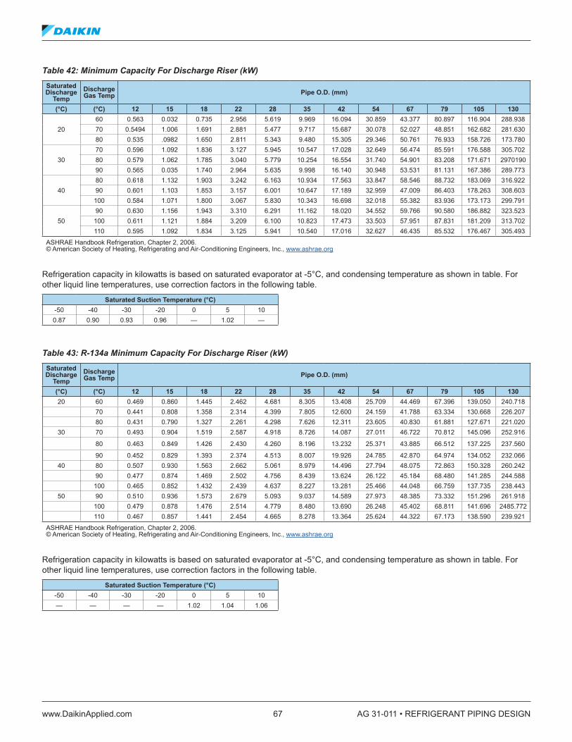
www.DaikinApplied.com 67 AG 31-011 • REFRIGERANT PIPING DESIGN
Table 42: Minimum Capacity For Discharge Riser (kW)Saturated Discharge
TempDischarge Gas Temp Pipe O .D . (mm)
(°C) (°C) 12 15 18 22 28 35 42 54 67 79 105 130
2060 0.563 0.032 0.735 2.956 5.619 9.969 16.094 30.859 43.377 80.897 116.904 288.93870 0.5494 1.006 1.691 2.881 5.477 9.717 15.687 30.078 52.027 48.851 162.682 281.63080 0.535 .0982 1.650 2.811 5.343 9.480 15.305 29.346 50.761 76.933 158.726 173.780
3070 0.596 1.092 1.836 3.127 5.945 10.547 17.028 32.649 56.474 85.591 176.588 305.70280 0.579 1.062 1.785 3.040 5.779 10.254 16.554 31.740 54.901 83.208 171.671 297019090 0.565 0.035 1.740 2.964 5.635 9.998 16.140 30.948 53.531 81.131 167.386 289.773
4080 0.618 1.132 1.903 3.242 6.163 10.934 17.563 33.847 58.546 88.732 183.069 316.92290 0.601 1.103 1.853 3.157 6.001 10.647 17.189 32.959 47.009 86.403 178.263 308.603
100 0.584 1.071 1.800 3.067 5.830 10.343 16.698 32.018 55.382 83.936 173.173 299.791
5090 0.630 1.156 1.943 3.310 6.291 11.162 18.020 34.552 59.766 90.580 186.882 323.523
100 0.611 1.121 1.884 3.209 6.100 10.823 17.473 33.503 57.951 87.831 181.209 313.702110 0.595 1.092 1.834 3.125 5.941 10.540 17.016 32.627 46.435 85.532 176.467 305.493
ASHRAE Handbook Refrigeration, Chapter 2, 2006. © American Society of Heating, Refrigerating and Air-Conditioning Engineers, Inc., www.ashrae.org
Refrigeration capacity in kilowatts is based on saturated evaporator at -5°C, and condensing temperature as shown in table. For other liquid line temperatures, use correction factors in the following table.
Saturated Suction Temperature (°C) -50 -40 -30 -20 0 5 100.87 0.90 0.93 0.96 — 1.02 —
Table 43: R-134a Minimum Capacity For Discharge Riser (kW)Saturated Discharge
TempDischarge Gas Temp Pipe O .D . (mm)
(°C) (°C) 12 15 18 22 28 35 42 54 67 79 105 13020 60 0.469 0.860 1.445 2.462 4.681 8.305 13.408 25.709 44.469 67.396 139.050 240.718
70 0.441 0.808 1.358 2.314 4.399 7.805 12.600 24.159 41.788 63.334 130.668 226.20780 0.431 0.790 1.327 2.261 4.298 7.626 12.311 23.605 40.830 61.881 127.671 221.020
30 70 0.493 0.904 1.519 2.587 4.918 8.726 14.087 27.011 46.722 70.812 145.096 252.916
80 0.463 0.849 1.426 2.430 4.260 8.196 13.232 25.371 43.885 66.512 137.225 237.560
90 0.452 0.829 1.393 2.374 4.513 8.007 19.926 24.785 42.870 64.974 134.052 232.06640 80 0.507 0.930 1.563 2.662 5.061 8.979 14.496 27.794 48.075 72.863 150.328 260.242
90 0.477 0.874 1.469 2.502 4.756 8.439 13.624 26.122 45.184 68.480 141.285 244.588100 0.465 0.852 1.432 2.439 4.637 8.227 13.281 25.466 44.048 66.759 137.735 238.443
50 90 0.510 0.936 1.573 2.679 5.093 9.037 14.589 27.973 48.385 73.332 151.296 261.918100 0.479 0.878 1.476 2.514 4.779 8.480 13.690 26.248 45.402 68.811 141.696 2485.772110 0.467 0.857 1.441 2.454 4.665 8.278 13.364 25.624 44.322 67.173 138.590 239.921
ASHRAE Handbook Refrigeration, Chapter 2, 2006. © American Society of Heating, Refrigerating and Air-Conditioning Engineers, Inc., www.ashrae.org
Refrigeration capacity in kilowatts is based on saturated evaporator at -5°C, and condensing temperature as shown in table. For other liquid line temperatures, use correction factors in the following table.
Saturated Suction Temperature (°C)-50 -40 -30 -20 0 5 10— — — — 1.02 1.04 1.06
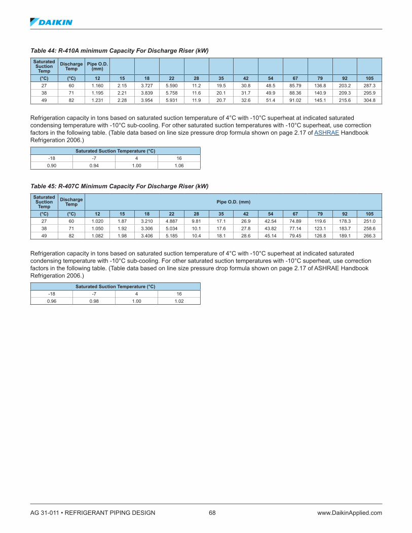
AG 31-011 • REFRIGERANT PIPING DESIGN 68 www.DaikinApplied.com
Table 44: R-410A minimum Capacity For Discharge Riser (kW) Saturated Suction Temp
Discharge Temp
Pipe O .D . (mm)
(°C) (°C) 12 15 18 22 28 35 42 54 67 79 92 10527 60 1.160 2.15 3.727 5.590 11.2 19.5 30.8 48.5 85.79 136.8 203.2 287.338 71 1.195 2.21 3.839 5.758 11.6 20.1 31.7 49.9 88.36 140.9 209.3 295.949 82 1.231 2.28 3.954 5.931 11.9 20.7 32.6 51.4 91.02 145.1 215.6 304.8
Refrigeration capacity in tons based on saturated suction temperature of 4°C with -10°C superheat at indicated saturated condensing temperature with -10°C sub-cooling. For other saturated suction temperatures with -10°C superheat, use correction factors in the following table. (Table data based on line size pressure drop formula shown on page 2.17 of ASHRAE Handbook Refrigeration 2006.)
Saturated Suction Temperature (°C)-18 -7 4 160.90 0.94 1.00 1.06
Table 45: R-407C Minimum Capacity For Discharge Riser (kW) Saturated Suction Temp
Discharge Temp Pipe O .D . (mm)
(°C) (°C) 12 15 18 22 28 35 42 54 67 79 92 10527 60 1.020 1.87 3.210 4.887 9.81 17.1 26.9 42.54 74.89 119.6 178.3 251.038 71 1.050 1.92 3.306 5.034 10.1 17.6 27.8 43.82 77.14 123.1 183.7 258.649 82 1.082 1.98 3.406 5.185 10.4 18.1 28.6 45.14 79.45 126.8 189.1 266.3
Refrigeration capacity in tons based on saturated suction temperature of 4°C with -10°C superheat at indicated saturated condensing temperature with -10°C sub-cooling. For other saturated suction temperatures with -10°C superheat, use correction factors in the following table. (Table data based on line size pressure drop formula shown on page 2.17 of ASHRAE Handbook Refrigeration 2006.)
Saturated Suction Temperature (°C)-18 -7 4 160.96 0.98 1.00 1.02
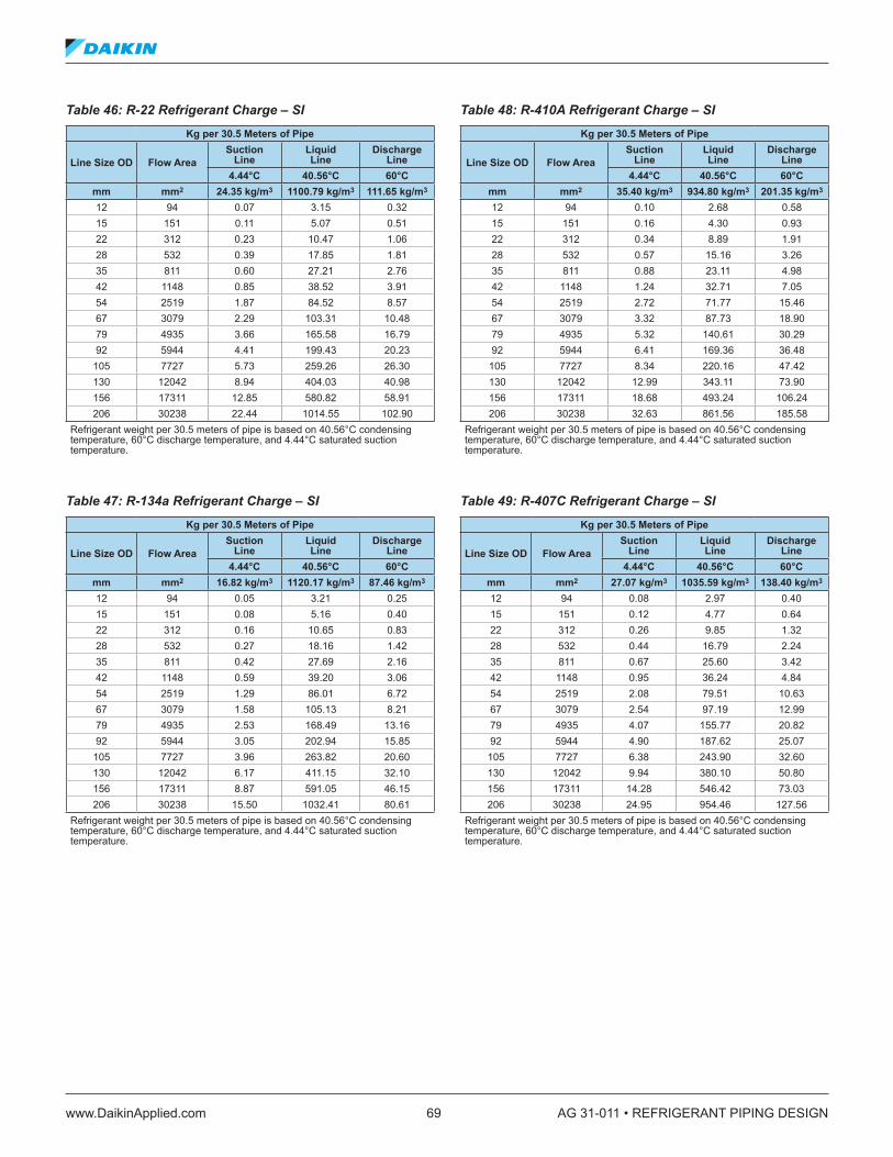
www.DaikinApplied.com 69 AG 31-011 • REFRIGERANT PIPING DESIGN
Table 46: R-22 Refrigerant Charge – SI Kg per 30 .5 Meters of Pipe
Line Size OD Flow AreaSuction
LineLiquid Line
Discharge Line
4 .44°C 40 .56°C 60°Cmm mm2 24 .35 kg/m3 1100 .79 kg/m3 111 .65 kg/m3
12 94 0.07 3.15 0.3215 151 0.11 5.07 0.5122 312 0.23 10.47 1.0628 532 0.39 17.85 1.8135 811 0.60 27.21 2.7642 1148 0.85 38.52 3.9154 2519 1.87 84.52 8.5767 3079 2.29 103.31 10.4879 4935 3.66 165.58 16.7992 5944 4.41 199.43 20.23
105 7727 5.73 259.26 26.30130 12042 8.94 404.03 40.98156 17311 12.85 580.82 58.91206 30238 22.44 1014.55 102.90
Refrigerant weight per 30.5 meters of pipe is based on 40.56°C condensing temperature, 60°C discharge temperature, and 4.44°C saturated suction temperature.
Table 47: R-134a Refrigerant Charge – SI Kg per 30 .5 Meters of Pipe
Line Size OD Flow AreaSuction
LineLiquid Line
Discharge Line
4 .44°C 40 .56°C 60°Cmm mm2 16 .82 kg/m3 1120 .17 kg/m3 87 .46 kg/m3
12 94 0.05 3.21 0.2515 151 0.08 5.16 0.4022 312 0.16 10.65 0.8328 532 0.27 18.16 1.4235 811 0.42 27.69 2.1642 1148 0.59 39.20 3.0654 2519 1.29 86.01 6.7267 3079 1.58 105.13 8.2179 4935 2.53 168.49 13.1692 5944 3.05 202.94 15.85
105 7727 3.96 263.82 20.60130 12042 6.17 411.15 32.10156 17311 8.87 591.05 46.15206 30238 15.50 1032.41 80.61
Refrigerant weight per 30.5 meters of pipe is based on 40.56°C condensing temperature, 60°C discharge temperature, and 4.44°C saturated suction temperature.
Table 48: R-410A Refrigerant Charge – SI Kg per 30 .5 Meters of Pipe
Line Size OD Flow AreaSuction
LineLiquid Line
Discharge Line
4 .44°C 40 .56°C 60°Cmm mm2 35 .40 kg/m3 934 .80 kg/m3 201 .35 kg/m3
12 94 0.10 2.68 0.5815 151 0.16 4.30 0.9322 312 0.34 8.89 1.9128 532 0.57 15.16 3.2635 811 0.88 23.11 4.9842 1148 1.24 32.71 7.0554 2519 2.72 71.77 15.4667 3079 3.32 87.73 18.9079 4935 5.32 140.61 30.2992 5944 6.41 169.36 36.48
105 7727 8.34 220.16 47.42130 12042 12.99 343.11 73.90156 17311 18.68 493.24 106.24206 30238 32.63 861.56 185.58
Refrigerant weight per 30.5 meters of pipe is based on 40.56°C condensing temperature, 60°C discharge temperature, and 4.44°C saturated suction temperature.
Table 49: R-407C Refrigerant Charge – SI Kg per 30 .5 Meters of Pipe
Line Size OD Flow AreaSuction
LineLiquid Line
Discharge Line
4 .44°C 40 .56°C 60°Cmm mm2 27 .07 kg/m3 1035 .59 kg/m3 138 .40 kg/m3
12 94 0.08 2.97 0.4015 151 0.12 4.77 0.6422 312 0.26 9.85 1.3228 532 0.44 16.79 2.2435 811 0.67 25.60 3.4242 1148 0.95 36.24 4.8454 2519 2.08 79.51 10.6367 3079 2.54 97.19 12.9979 4935 4.07 155.77 20.8292 5944 4.90 187.62 25.07
105 7727 6.38 243.90 32.60130 12042 9.94 380.10 50.80156 17311 14.28 546.42 73.03206 30238 24.95 954.46 127.56
Refrigerant weight per 30.5 meters of pipe is based on 40.56°C condensing temperature, 60°C discharge temperature, and 4.44°C saturated suction temperature.

AG 31-011 • REFRIGERANT PIPING DESIGN 70 www.DaikinApplied.com
Figure 29: R-22 Suction Gas Velocity – SI
Figure 29 is based on 4.4°C suction temperature and 41°C condensing temperature. For other conditions, apply correction factors from Table 50.
Table 50: R-22 Suction Gas Velocity Correction Factors – SI
Condenser Temp (°C)
Suction Temperature (°C)-12 .2 -9 .4 -6 .7 -3 .9 -1 .1 1 .7 4 .5 7 .2 10 .0
29.5 1.63 1.48 1.34 1.21 1.10 1.00 0.92 0.84 0.7632.2 1.67 1.51 1.37 1.24 1.13 1.02 0.93 0.85 0.7835.0 1.71 1.54 1.40 1.27 1.15 1.05 0.95 0.87 0.8037.8 1.75 1.58 1.43 1.30 1.18 1.07 0.98 0.89 0.8240.6 1.79 1.62 1.46 1.33 1.20 1.10 1.00 0.91 0.8343.4 1.84 1.66 1.50 1.36 1.24 1.12 1.02 0.94 0.8646.1 1.89 1.70 1.54 1.39 1.27 1.15 1.05 0.96 0.8848.9 1.94 1.75 1.58 1.43 1.30 1.18 1.08 0.98 0.9051.7 1.99 1.80 1.63 1.47 1.34 1.22 1.11 1.01 0.9254.5 2.05 1.85 1.67 1.52 1.38 1.25 1.14 1.04 0.9557.3 2.12 1.91 1.73 1.56 1.42 1.29 1.17 1.07 0.9860.0 2.19 1.97 1.78 1.61 1.46 1.33 1.21 1.10 1.0162.8 2.27 2.04 1.84 1.67 1.51 1.37 1.25 1.14 1.04

www.DaikinApplied.com 71 AG 31-011 • REFRIGERANT PIPING DESIGN
Figure 30: R-134a Suction Gas Velocity – SI
Figure 30 is based on 4.4°C suction temperature and 41°C condensing temperature. For other conditions, apply correction factors from Table 51.
Table 51: R-134a Suction Gas Velocity Correction Factors – SI
Condenser Temp (°C)
Suction Temperature (°C)-12 .2 -9 .4 -6 .7 -3 .9 -1 .1 1 .7 4 .5 7 .2 10 .0
29.5 1.76 1.56 1.40 1.25 1.12 1.00 0.90 0.82 0.7432.2 1.81 1.61 1.43 1.28 1.15 1.03 0.93 0.84 0.7635.0 1.86 1.65 1.47 1.32 1.18 1.06 0.95 0.86 0.7737.8 1.91 1.70 1.52 1.35 1.21 1.09 0.98 0.88 0.8040.6 1.97 1.75 1.56 1.39 1.25 1.12 1.00 0.91 0.8243.4 2.04 1.81 1.61 1.44 1.29 1.15 1.04 0.93 0.8446.1 2.10 1.87 1.66 1.48 1.33 1.19 1.07 0.96 0.8748.9 2.18 1.93 1.72 1.53 1.37 1.23 1.10 0.99 0.9051.7 2.26 2.00 1.78 1.59 1.42 1.27 1.14 1.03 0.9254.5 2.35 2.08 1.85 1.65 1.47 1.32 1.18 1.06 0.9657.3 2.44 2.16 1.92 1.71 1.53 1.37 1.23 1.10 0.9960.0 2.55 2.26 2.00 1.78 1.59 1.42 1.27 1.14 1.0362.8 2.66 2.36 2.09 1.86 1.66 1.48 1.33 1.19 1.07
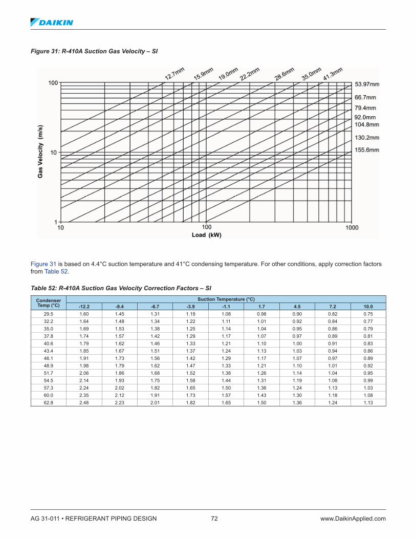
AG 31-011 • REFRIGERANT PIPING DESIGN 72 www.DaikinApplied.com
Figure 31: R-410A Suction Gas Velocity – SI
Figure 31 is based on 4.4°C suction temperature and 41°C condensing temperature. For other conditions, apply correction factors from Table 52.
Table 52: R-410A Suction Gas Velocity Correction Factors – SI
Condenser Temp (°C)
Suction Temperature (°C)-12 .2 -9 .4 -6 .7 -3 .9 -1 .1 1 .7 4 .5 7 .2 10 .0
29.5 1.60 1.45 1.31 1.19 1.08 0.98 0.90 0.82 0.7532.2 1.64 1.48 1.34 1.22 1.11 1.01 0.92 0.84 0.7735.0 1.69 1.53 1.38 1.25 1.14 1.04 0.95 0.86 0.7937.8 1.74 1.57 1.42 1.29 1.17 1.07 0.97 0.89 0.8140.6 1.79 1.62 1.46 1.33 1.21 1.10 1.00 0.91 0.8343.4 1.85 1.67 1.51 1.37 1.24 1.13 1.03 0.94 0.8646.1 1.91 1.73 1.56 1.42 1.29 1.17 1.07 0.97 0.8948.9 1.98 1.79 1.62 1.47 1.33 1.21 1.10 1.01 0.9251.7 2.06 1.86 1.68 1.52 1.38 1.26 1.14 1.04 0.9554.5 2.14 1.93 1.75 1.58 1.44 1.31 1.19 1.08 0.9957.3 2.24 2.02 1.82 1.65 1.50 1.36 1.24 1.13 1.0360.0 2.35 2.12 1.91 1.73 1.57 1.43 1.30 1.18 1.0862.8 2.48 2.23 2.01 1.82 1.65 1.50 1.36 1.24 1.13

www.DaikinApplied.com 73 AG 31-011 • REFRIGERANT PIPING DESIGN
Figure 32: R-407C Suction Gas Velocity – SI
Figure 32 is based on 4.4°C suction temperature and 41°C condensing temperature. For other conditions, apply correction factors from Table 53.
Table 53: R-407C Suction Gas Velocity Correction Factors – SI
Condenser Temp (°C)
Suction Temperature (°C)-12 .2 -9 .4 -6 .7 -3 .9 -1 .1 1 .7 4 .5 7 .2 10 .0
29.5 1.78 1.49 1.35 1.21 1.10 0.99 0.90 0.82 0.7532.2 1.82 1.53 1.38 1.24 1.12 1.02 0.92 0.84 0.7635.0 1.75 1.57 1.42 1.28 1.15 1.04 0.95 0.86 0.7837.8 1.80 1.62 1.46 1.31 1.19 1.07 0.97 0.88 0.8040.6 1.86 1.78 1.50 1.35 1.22 1.10 1.00 0.91 0.8343.4 1.91 1.72 1.54 1.39 1.26 1.14 1.03 0.93 0.8546.1 1.98 1.77 1.59 1.43 1.29 1.17 1.06 0.96 0.8748.9 2.04 1.83 1.75 1.48 1.34 1.21 1.09 0.99 0.9051.7 2.12 1.90 1.81 1.53 1.38 1.25 1.13 1.03 0.9354.5 2.20 1.97 1.77 1.59 1.43 1.29 1.17 1.06 0.9657.3 2.29 2.05 1.84 1.76 1.49 1.34 1.22 1.10 1.0060.0 2.38 2.13 1.91 1.72 1.55 1.40 1.26 1.15 1.0462.8 2.49 2.23 2.00 1.79 1.72 1.46 1.32 1.19 1.08

AG 31-011 • REFRIGERANT PIPING DESIGN 74 www.DaikinApplied.com
Figure 33: R-22 Discharge Gas Velocity – SI
Figure 33 is based on 28°C discharge temperature and 5°C condensing temperature. For other conditions, apply correction factors from Table 54.
Table 54: R-22 Discharge Gas Velocity Correction Factors – SI
Condenser Temp (°C)
Suction Temperature (°C)65 .6 71 .2 76 .7 82 .3 87 .8 93 .4 99 .0 104 .5 110 .1
29.5 1.20 1.22 1.25 1.28 1.31 1.34 1.37 1.39 1.4232.2 1.12 1.14 1.17 1.20 1.23 1.25 1.28 1.31 1.3335.0 1.05 1.07 1.10 1.13 1.15 1.18 1.21 1.23 1.2637.8 0.98 1.01 1.03 1.06 1.08 1.11 1.14 1.16 1.1940.6 0.92 0.95 0.97 1.00 1.02 1.05 1.07 1.10 1.1243.4 0.86 0.89 0.91 0.94 0.96 0.99 1.01 1.04 1.0646.1 0.81 0.84 0.86 0.89 0.91 0.93 0.96 0.98 1.0148.9 0.76 0.79 0.81 0.84 0.86 0.88 0.91 0.93 0.9651.7 0.72 0.74 0.76 0.79 0.81 0.84 0.86 0.88 0.9154.5 0.67 0.70 0.72 0.74 0.77 0.79 0.82 0.84 0.8757.3 0.63 0.65 0.68 0.70 0.73 0.75 0.78 0.80 0.8260.0 0.59 0.62 0.64 0.67 0.69 0.72 0.74 0.77 0.7962.8 0.55 0.58 0.60 0.63 0.66 0.68 0.71 0.73 0.76
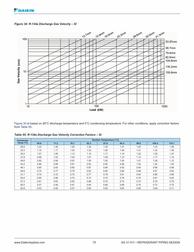
www.DaikinApplied.com 75 AG 31-011 • REFRIGERANT PIPING DESIGN
Figure 34: R-134a Discharge Gas Velocity – SI
Figure 34 is based on 28°C discharge temperature and 5°C condensing temperature. For other conditions, apply correction factors from Table 55.
Table 55: R-134a Discharge Gas Velocity Correction Factors – SI
Condenser Temp (°C)
Suction Temperature (°C)65 .6 71 .2 76 .7 82 .3 87 .8 93 .4 99 .0 104 .5 110 .1
29.5 1.23 1.26 1.29 1.32 1.35 1.37 1.40 1.43 1.4632.2 1.15 1.17 1.20 1.23 1.26 1.28 1.31 1.34 1.3635.0 1.07 1.09 1.12 1.14 1.17 1.19 1.22 1.25 1.2737.8 0.99 1.02 1.04 1.07 1.09 1.12 1.14 1.17 1.1940.6 0.92 0.95 0.97 1.00 1.02 1.04 1.07 1.09 1.1243.4 0.86 0.88 0.91 0.93 0.95 0.98 1.00 1.02 1.0546.1 0.80 0.83 0.85 0.87 0.89 0.92 0.94 0.96 0.9948.9 0.75 0.77 0.79 0.82 0.84 0.86 0.88 0.91 0.9351.7 0.70 0.72 0.75 0.77 0.79 0.81 0.83 0.86 0.8854.5 0.65 0.68 0.70 0.72 0.74 0.76 0.79 0.81 0.8357.3 0.61 0.63 0.65 0.68 0.70 0.72 0.74 0.76 0.7960.0 0.57 0.59 0.61 0.64 0.66 0.68 0.70 0.72 0.7562.8 0.53 0.55 0.57 0.60 0.62 0.64 0.66 0.69 0.71
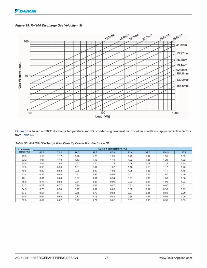
AG 31-011 • REFRIGERANT PIPING DESIGN 76 www.DaikinApplied.com
Figure 35: R-410A Discharge Gas Velocity – SI
Figure 35 is based on 28°C discharge temperature and 5°C condensing temperature. For other conditions, apply correction factors from Table 56.
Table 56: R-410A Discharge Gas Velocity Correction Factors – SI
Condenser Temp (°C)
Suction Temperature (°C)65 .6 71 .2 76 .7 82 .3 87 .8 93 .4 99 .0 104 .5 110 .1
29.5 1.13 1.17 1.20 1.23 1.26 1.29 1.32 1.35 1.3932.2 1.07 1.10 1.13 1.16 1.19 1.22 1.25 1.29 1.3235.0 1.01 1.04 1.07 1.10 1.13 1.16 1.19 1.22 1.2537.8 0.95 0.98 1.01 1.04 1.07 1.10 1.13 1.17 1.2040.6 0.90 0.93 0.96 0.99 1.02 1.05 1.08 1.11 1.1543.4 0.85 0.88 0.91 0.95 0.98 1.01 1.04 1.07 1.1046.1 0.81 0.84 0.87 0.91 0.94 0.97 1.00 1.03 1.0648.9 0.77 0.80 0.84 0.87 0.90 0.93 0.97 1.00 1.0351.7 0.73 0.77 0.80 0.84 0.87 0.91 0.94 0.97 1.0154.5 0.70 0.74 0.77 0.81 0.85 0.88 0.92 0.96 0.9957.3 0.67 0.71 0.75 0.79 0.83 0.87 0.91 0.95 0.9960.0 0.64 0.69 0.73 0.78 0.82 0.86 0.91 0.95 1.0062.8 0.61 0.67 0.72 0.77 0.82 0.87 0.93 0.98 1.03
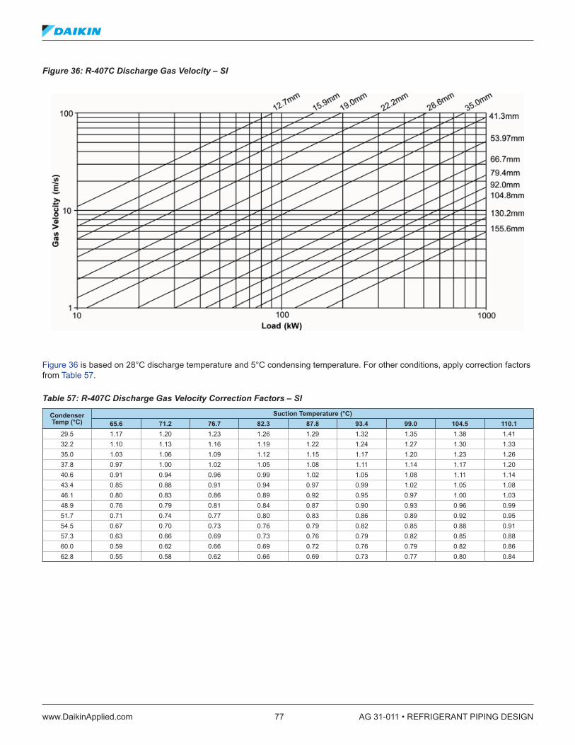
www.DaikinApplied.com 77 AG 31-011 • REFRIGERANT PIPING DESIGN
Figure 36: R-407C Discharge Gas Velocity – SI
Figure 36 is based on 28°C discharge temperature and 5°C condensing temperature. For other conditions, apply correction factors from Table 57.
Table 57: R-407C Discharge Gas Velocity Correction Factors – SI
Condenser Temp (°C)
Suction Temperature (°C)65 .6 71 .2 76 .7 82 .3 87 .8 93 .4 99 .0 104 .5 110 .1
29.5 1.17 1.20 1.23 1.26 1.29 1.32 1.35 1.38 1.4132.2 1.10 1.13 1.16 1.19 1.22 1.24 1.27 1.30 1.3335.0 1.03 1.06 1.09 1.12 1.15 1.17 1.20 1.23 1.2637.8 0.97 1.00 1.02 1.05 1.08 1.11 1.14 1.17 1.2040.6 0.91 0.94 0.96 0.99 1.02 1.05 1.08 1.11 1.1443.4 0.85 0.88 0.91 0.94 0.97 0.99 1.02 1.05 1.0846.1 0.80 0.83 0.86 0.89 0.92 0.95 0.97 1.00 1.0348.9 0.76 0.79 0.81 0.84 0.87 0.90 0.93 0.96 0.9951.7 0.71 0.74 0.77 0.80 0.83 0.86 0.89 0.92 0.9554.5 0.67 0.70 0.73 0.76 0.79 0.82 0.85 0.88 0.9157.3 0.63 0.66 0.69 0.73 0.76 0.79 0.82 0.85 0.8860.0 0.59 0.62 0.66 0.69 0.72 0.76 0.79 0.82 0.8662.8 0.55 0.58 0.62 0.66 0.69 0.73 0.77 0.80 0.84
AG 31-011 (02/19) ©2019 Daikin Applied | (800) 432–1342 | www.DaikinApplied.com


