Ck024c Quick Connect Couplings for refrigeration, automotive and air conditioning industries REFRIGERATION, AUTOMOTIVE & AIR CONDITIONING CUPLA SERIES GENERAL CATALOG Quick Connect Couplings Products Comply with RoHS Directive
Transcript
Ck024c
Quick Connect Couplings for refrigeration, automotive and air conditioning industries
REFRIGERATION, AUTOMOTIVE& AIR CONDITIONING
CUPLA SERIESGENERAL CATALOG
Quick Connect Couplings
Products Complywith RoHS Directive
• Diverse applications from general household to high-tech industries such as in oceanic and space development.• Numerous sizes are available for various needs.• Wide varieties of body materials such as steel, brass, plastic, aluminum or stainless steel are available.
A profusion of patented technology and recognitionof high quality and high performance by global users.
ISO 9001 and 14001 Certification Award“Cuplas“ quick connect couplings are produced as the crystallization of high-grade know-how nurtured in the fields of fluid engineering and materials engineering, and top level precision machining technology. Having assessed Nitto Kohki consistent quality assurance and control system ranging from design and development through procurement of material, manufacture, assembly, and shipping, the Japan Quality Assurance Foundation, authority for inspection and registration, awarded us “ISO 9001“, international standard for quality management systems, and “ISO 14001“, international standard for environment management systems intended to perform global environment preservation and pollution control. High reliability built on unparalleled “high quality“ and accumulated history of “productivity“ for stable supply. Cupla is receiving overwhelming support from many users spread all over the world as the top brand for fluid energy transmission and control.
Cuplas Enable Flexible, Fast,and Secure Connections for Various Fluid Lines.
Replacements of pneumatic / hydraulic tools, pneumatic /hydraulic cylinders, mold attachments, etc.
For easy replacements:
Vacuum tests, pressure durability tests, leakage tests,running tests, etc.
For temporary installation in test line:
For filling up various industrial gases, including inert gases,nitrogen, LPG, carbon dioxide, oxygen, fuel gas, etc.
For filling:
For computer cooling system, hydraulic cylinders indie-casting machines.
For maintenance services:
For transfer of solid items through pipes such as screws andnuts as well as for electric power cable lines.
For transfer:
Applications other than fluid transfer covering connectionsfor holding works while anchored or carried around.
As joints:
ISO 14001JQA-EM4057
NITTO KOHKI CO.,LTD.ISO 14001
ISO 9001JQA-2025
NITTO KOHKI CO.,LTD.Couplings DivisionISO 9001
Nitto Kohki’s unique technologies and dedicated research have been proven by numerouspatents, which led to the development of 25,000 different Cupla variations.
Recently on the market, there have appeared similar products that invite misidentification or confusion with Nitto Kohki Cuplas, or such productsthat claim to have compatible mating parts. Nitto Kohki cannot accept responsibility for any accident that may result by mixed use with a couplingof another brand that seems connectable to a Nitto Kohki Cupla. Nitto Kohki Cuplas are produced with their own unique tolerances and precisionunder strict quality control, and are not interchangeable with other couplings that are not under such tolerances. Therefore, connection to otherbrand of coupling may end up with abrupt breakdown or personal injury. Please be sure to check for our marks below, which are always inscribedon Nitto Kohki Cupla products, when you order and purchase.
Beware of imitations
1
Green ProcurementNitto Kohki has made every effort in developing “EnvironmentalImprovement Plans” through the implementation of ISO14001,to execute environmentally conscious business activities on acompany-wide basis. As a part of our ongoing commitment to theenvironment, we are also committed to reduce and/or excluderestricted chemical substances from our products as designatedby RoHS directives, laws and regulations of chemical substancesin Japan. For further details, please visit www.nitto-kohki.co.jp/e/.
Specifications to Be Checked When Selecting Cuplas
Fluid and theTemperature
Fluid Pressure
AutomaticShut-off Valve
OperatingEnvironment
Size and Type ofEnd Configurations
GlossaryBody MaterialIndicates the material that is used for the plug body or socket body that formsthe flow path of fluid through the Cupla. Some products have internalcomponents of a different material. Please check with us for details.
SizeIndicates the nominal size of the pipe thread connection or of the hose to beused.
Working pressureThe normal allowable fluid pressure under continuous use.
Pressure LossThe loss of pressure when fluid runs through the Cupla set.
Min. Cross-Sectional AreaThe minimum cross-sectional area of the fluid path when the Cupla is connected.
Working Temperature RangeThe minimum and maximum temperature, in-between which the Cupla with theseal material can be used. However, it does not mean that they can be usedcontinuously at the minimum or maximum working temperatures.Please check with us if you need Cuplas in such extreme applications.
Automatic Shutoff ValvesThe structure of valves that open on connection and shut on disconnectionautomatically.
Suitability for VacuumIndicates if the Cupla has necessary performance required for vacuumapplications. (Note that the required performance is different in connectionand in disconnection.)
Max. Tightening TorqueConsidering the balance between possible leakage caused by loose fit and toomuch structural stress when a Cupla is mounted on a workpiece, the appropriatescrew-in torque value is suggested by the maker.
Flow DirectionThe design of some Cuplas may restrict the fluid flow direction only to one way.Check the maker’s suggested direction before installation.
InterchangeabilityIndicates whether the Cupla plug and socket can be connected with each other.
Seal MaterialThis shows the material used to seal the Cupla, usually an O-ring.
Properties of rubbers used for O-rings
Nitrile rubber NBR(SG)
-20°C to +80°C Standard seal with excellent oil resistance.
Hydrogenatednitrile rubber
HNBR(H708) -20°C to +120°C
Compared with the standard nitrile rubber,the seal material is more heat and weatherresistant. In addition to these features, theseal material can also be used forrefrigeration oil and refrigerant applicationssuch as HFC-134a.
FKM(X-100) -20°C to +180°C Excellent for heat, weather, and oil resistance.
Applicable to wide range of applications.Fluoro rubber
CR(X-306)
-20°C to +80°C Excellent weather resistance.Chloroprene
rubberCR
(C308)-20°C to +80°C
In addition to the above features, the sealmaterial can also be used for refrigerantapplications such as HFC-134a.
Note: 1. Even among rubber materials of the same category, the working temperature range differs depending upon the design of the Cuplas. For details, see the specifications of each Cupla series. As for the Nitto symbol for rubber material, fluoro rubber is designated as “FKM” or “X-100” for example.2. The above are general features, but the seal resistance depends on fluid temperature, fluid concentration, and additives contained in the fluid.
Seal material
Common name MarkWorking
Temperature Range Features
International System of Units (SI Units) Units stated in this catalog are based on SI Units. The old units, which are Non-SI Units,are also written within parentheses side by side with SI Units for reference only.
Select a Cupla with body andseal materials that suit thefluid and its temperature.
Select a Cupla suitable for theactual max. fluid pressure.
Select a Cupla with a valvestructure that suits the pipingapplication.
Select a Cupla with design andmaterials that suit eachoperating environment.
Finally and critically specifythe size and type of endconfigurations.
There are different body and seal materials to suit different fluids. For example, we recommend steel for air,and brass or stainless steel for water.
Fluid pressure is also a key to Cupla selection. Each Cupla has a different structure to cope with eachpressure resistance range.
Valve combinations are two-way shut-off, one-way shut-off, or straight through types. Choose carefully.Unless it is a two-way shut-off type, the internal fluid will flow out from the Cupla when it is disconnected.
In choosing the type of Cupla, body material and seal material, consider the temperature range, possible dirtand dust, and/or corrosive atmosphere in the operating environment.
Having checked the type and materials for the Cupla,now specify the size and type of end configurationsto suit the type of piping. Choose carefully, as thesize affects the fluid flow rate.
Note: End configuration and size may be limited by the type of Cuplas.
Femalethread
Nut
Hosebarb
Malethread
2
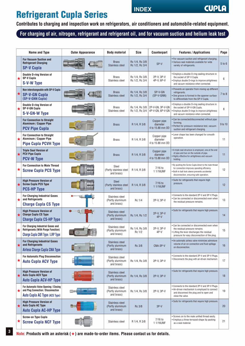
For charging of air, nitrogen, refrigerant and refrigerant oil, and for vacuum suction and helium leak test
Contributes to charging and inspection work on refrigerators, air conditioners and automobile-related equipment.
Refrigerant Cupla Series
Name and Type Outer Appearance Body material Size Features / Applications Page
Rc 1/4, Rc 3/8Rc 1/2, Rc 3/4 5 to 6
• For vacuum suction and refrigerant charging.• Various seal materials available for wide variety of refrigerants.
Rc 1/4, Rc 3/8Rc 1/2, Rc 3/4 6
• Employs a double O-ring sealing structure in the socket of SP-V Cupla.• Employs double O-rings to improve airtightness and vacuum resistance when connected.
Rc 1/4, Rc 3/8Rc 1/2, Rc 3/4 7 to 8
• Prevents an operator from mixing up different refrigerants.• One groove is formed in the spanner surface to differentiate from the SP-V Cupla.
Rc 1/4, Rc 3/8Rc 1/2, Rc 3/4 8
• Employs a double O-ring sealing structure in the socket of SP-V-GN Cupla.• Employs double O-rings to improve airtightness and vacuum resistance when connected.
R 1/4, R 3/8 9 to 10
• Can be connected/disconnected without pipe forming.• Perfect for pressure resistance test, vacuum suction and refrigerant charging.
R 1/4, R 3/8 11
• Lever shape has been changed for smooth operation.
R 1/4, R 3/8 11
• A triple seal structure is employed, one at the end of pipe and two on the outside of pipe.• Highly effective for airtightness and vacuum holding.
R 1/4, R 3/8 12
• By pushing the Screw Cupla direct to the male thread for connection improves operating efficiency.• Built-in ball lock sleeve prevents accidental disconnection, ensuring safe operation.
R 1/4, R 3/8 12
• Suits for refrigerants that require high pressure.
R 1/4, R 3/8 21
• Screws on to the male unified thread easily.• Employs a three-terraced-shape lip packing as a seal material.
Rc 1/4 13
• Connects to the standard 2P-V and 3P-V Plugs.• Can be connected or disconnected even when the residual pressure remains.
Rc 1/4, Rc 1/2 14
• Suits for refrigerants that require high pressure.
Rc 1/4, Rc 3/8Rc 1/2 15
• Can be connected or disconnected even when the residual pressure remains.• Lifting the lever discharges the residual pressure for easy disconnection of the plug.
Rc 3/8 16
• An automatic airless valve minimizes admixture volume of air on connection and fluid spillage on disconnection.
Rc 1/4, Rc 3/8 17
• Connects to the standard 2P-V and 3P-V Plugs.• Disconnects the plug with air-driven mechanism.
Rc 1/4, Rc 3/8 18
• Suits for refrigerants that require high pressure.
Rc 1/4, Rc 3/8 19
• Connects to the standard 2P-V and 3P-V Plugs.• Air-driven mechanism is employed to connect and disconnect the plug and to open and close the valve.
Rc 3/8
Counterpart
SP-V
2P-V, 3P-V4P-V, 6P-V
SP-V-GN(SP-V-GNN)
2P-V-GN, 3P-V-GN4P-V-GN, 6P-V-GN
Copper pipediameter
4 to 15.88 mm OD
Copper pipediameter
4 to 15.88 mm OD
Copper pipediameter
4 to 15.88 mm OD
7/16 to1 1/16UNF
7/16 to1 1/16UNF
7/16 to1 1/16UNF
2P-V, 3P-V
2P-V, 3P-V4P-V
2P-V, 3P-V4P-V
CNA-3P-V
2P-V, 3P-V
2P-V, 3P-V
2P-V, 3P-V
3P-V 20
• Suits for refrigerants that require high pressure.
Note: Products with an asterisk ( ) are made-to-order items. Please contact us for details.
For Vacuum Suction andRefrigerant Charging
SP-V CuplaDouble O-ring Version ofSP-V Cupla
S-V-W TypeNon-interchangeable with SP-V Cupla
SP-V-GN Cupla(SP-V-GNN Cupla)
Double O-ring Version ofSP-V-GN Cupla
S-V-GN-W TypeFor Connection to StraightAluminum / Copper Pipe
PCV Pipe CuplaFor Connection to StraightAluminum / Copper Pipe
Pipe Cupla PCVH TypeTriple Seal Version ofPCV Pipe Cupla
PCV-W TypeFor Connection to Male Thread
Screw Cupla PCS Type
High Pressure Version ofScrew Cupla PCS Type
PCS-HP Type
Screw-on Type Cupla
Screw Cupla NCF Type
For Charging Industrial Gasesand Refrigerants
Charge Cupla CS TypeHigh Pressure Version ofCharge Cupla CS Type
Directly connects with any type of pipe end configurations.Pipe Cupla Series
Name and Type Outer Appearance Body material Size Features / Applications Page
Specifiedby a customer 23
• Employs a special chuck lock system to reduce lock scratches and improve pressure resistance.
Specifiedby a customer 23
• Employs a ball lock system to grip on the outer surface of pipe.
Specifiedby a customer 24
• Employs a double-row ball lock system to grip on the outer surface of pipe securely.
Specifiedby a customer 24
• Employs plastic chucks that scarcely scratches pipes.
Specifiedby a customer 25
• Employs a ball lock system to grip on the outer surface of pipe. Improved connection and disconnection with lever operation.
Specifiedby a customer 25
• Employs a ball lock system to grip on the outer surface of pipe. Improved connection and disconnection with lever operation.
Specifiedby a customer 26
• Combination of PCV Pipe Cupla and the residual pressure release device for easy disconnection.• Raising the lever of the residual pressure release device discharges the residual pressure for easy pipe disconnection.
Specifiedby a customer 26
• Suits for connection and disconnection with pipe fittings. A ball lock system grips on the rear of the hex. nut of pipe fitting upon connection.
Specifiedby a customer 27
• Unique lock design on pipes allows some slight variations in pipe dimensions.
Specifiedby a customer 27
• Suits for connection and disconnection with large diameter straight pipes.
Specifiedby a customer 28
• Suits for connection and disconnection with pipe fittings.
Specifiedby a customer
28
• A special chuck lock system is employed to reduce lock scratches and improve pressure resistance.
Specifiedby a customer 29
• By pushing the Screw Cupla direct to the female thread for connection improves operating efficiency.
Specifiedby a customer 29
• Employs balls to lock at the leading end of workpiece from the inside.
Specifiedby a customer 30
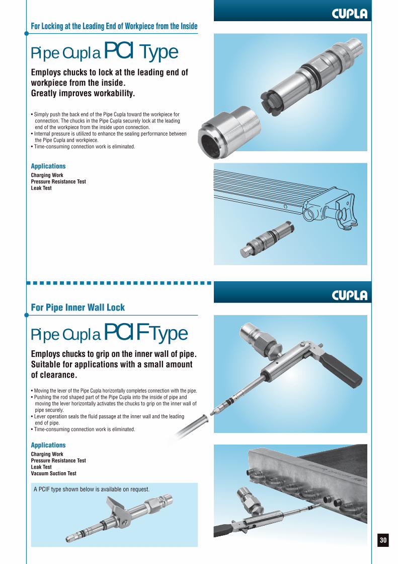
• Employs chucks to lock at the leading end of workpiece from the inside.
Specifiedby a customer 30
• Employs chucks to grip on the inner wall of pipe. Suitable for applications with a small amount of clearance.
Specifiedby a customer 31
• Air-driven mechanism is employed in the Auto Cupla to disconnect the pipe automatically.
Specifiedby a customer
Counterpart
Based oncustomer’spipe size
dimensions
Based oncustomer’spipe size
dimensions
Based oncustomer’spipe size
dimensions
Based oncustomer’spipe size
dimensions
Based oncustomer’spipe size
dimensions
Based oncustomer’spipe size
dimensions
Based oncustomer’spipe size
dimensions
Based oncustomer’spipe size
dimensions
Based oncustomer’spipe size
dimensions
Based oncustomer’spipe size
dimensions
Based oncustomer’swork size
dimensions
Based oncustomer’spipe size
dimensions
Based oncustomer’sthread sizedimensions
Based oncustomer’swork size
dimensions
Based oncustomer’swork size
dimensions
Based oncustomer’spipe size
dimensions
Based oncustomer’spipe size
dimensions
Refrigerantcharge valves used
in car air conditionerproduction lines
31
• Quick connection and disconnection with refrigerant charge valves used in car air conditioner production lines.
Caution for Custom-made CuplasCustom-made Cuplas are products designed and produced based on the specifications presented by the customer. Prior to actual production, technical documentation presented by us (drawings, specificationsheets, etc.) shall be exchanged and approved by the customer. For the use of the product, the customer shall check the safety and the full compatibility with the equipment used by evaluating its performancethoroughly, under actual operating conditions. We shall in no case be liable for any loss or damage if the Cupla is used outside the conditions and specifications set out in the original technical documentation.
Equipped with Special Chuck Lock Systemfor Expanded Pipes and Bulged Pipes
PCV Pipe Cupla with ResidualPressure Release Device
For Pipes with Fittings
Pipe Cupla PCB Type
For Straight Pipes and Pipeswith Blind Rubber Plugs
Pipe Cupla PCW TypeFor Large DiameterStraight Pipes
Pipe Cupla PCA TypeFor Special Pipes
Pipe Cupla PCD Type
High Pressure Typefor Spool Pipes
Pipe Cupla PCH TypeFor connecting directly to thefemale thread
Screw Cupla PCSI TypeFor Locking at the Leading Endof Workpiece from the Inside
Pipe Cupla PCBI TypeFor Locking at the Leading Endof Workpiece from the Inside
Pipe Cupla PCI TypeFor Pipe Inner Wall Lock
Pipe Cupla PCIF Type
For Automatic Pipe Disconnection
Auto Cupla APCB Type
For Refrigerant Charge Valves Used inCar Air Conditioner Production Lines
PCB Type Cupla for Charge Valves
Stainless steel
BrassStainless steel
BrassStainless steel
Plastic(Partly stainless steel)
Stainless steel(Partly aluminum
and brass)
Brass(Partly steel)
Brass(Partly stainless steel
and steel)
BrassStainless steel
Brass(Partly stainless steel
and steel)
Stainless steel(Partly steel)
Stainless steel(Partly aluminum)
Stainless steel
Stainless steel(Partly aluminum)
Stainless steel(Partly aluminum)
Stainless steel(Partly aluminum
and steel)
Stainless steel
Stainless steel
Brass(Partly stainless steel)
Note: Products with an asterisk ( ) are made-to-order items. Please contact us for details. 4
INDEX
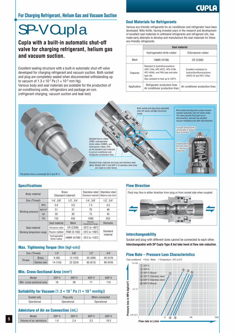
SP-V CuplaFor Charging Refrigerant, Helium Gas and Vacuum Suction
Cupla with a built-in automatic shut-offvalve for charging refrigerant, helium gasand vacuum suction.
Excellent sealing structure with a built-in automatic shut-off valvedeveloped for charging refrigerant and vacuum suction. Both socketand plug are completely sealed when disconnected withstanding upto vacuum of 1.3 x 10⁻¹ Pa (1 × 10⁻³ mm Hg).Various body and seal materials are available for the production ofair-conditioning units, refrigerators and package air-con.(refrigerant charging, vacuum suction and leak test)
The photos show a connected 3S-V and 3P-V.
Seal material
Hydrogenated nitrile rubber
Refrigerator production linesAir conditioner production lines
Air conditioner production lines
HNBR (H708) CR (C308)
Chloroprene rubber
Features
Mark
Application
Seal Materials for RefrigerantsVarious eco-friendly refrigerants for air conditioner and refrigerator have beendeveloped. Nitto Kohki, having invested years in the research and developmentof excellent seal materials to withstand refrigerants and refrigerant oils, hasmade early attempts to develop and manufacture the seal materials for theseeco-friendly refrigerants.
Interchangeability
Flow Rate – Pressure Loss Characteristics[Test conditions] • Fluid : Water • Temperature : 24˚C ± 6˚C
Socket and plug with different sizes cannot be connected to each other.Interchangeable with SP Cupla Type A but take heed of flow rate reduction.
Flow Direction
Fluid may flow in either direction from plug or from socket side when coupled.
Max. Tightening Torque (Nm {kgf •cm})1/4"
9 {92}
14 {143}
3/8"
12 {122}
22 {224}
1/2"
30 {306}
60 {612}
3/4"
50 {510}
90 {918}
Size (Thread)
Brass
Stainless steelTorque
Min. Cross-Sectional Area (mm2)2SP-V
18
3SP-V
38
4SP-V
71
6SP-V
110
Model
Min. cross-sectional area
2SP-V
1.0
3SP-V
2.4
4SP-V
3.2
6SP-V
10.5
Model
Volume of air admixture
Suitability for Vacuum (1.3 × 10⁻¹ Pa {1 × 10⁻³ mmHg})Plug only
Operational
When connected
Operational
Socket only
Operational
Admixture of Air on Connection (mL)
1 10 100 1000
1.0 {10}
0.1 {1}
0.01 {0.1}
2SP-V3SP-V4SP-V (Brass)
4SP-V (Stainless steel)
6SP-V (Stainless steel)
6SP-V (Brass)
Flow rate in L/min
Pres
sure
loss
in M
Pa {k
gf/c
m2 }
Specifications
Body material
Size (Thread)
Working pressure
Seal material
Working temperature range
1/4", 3/8"
5.0
51
50
725
Seal material
Chloroprene rubber
Fluoro rubberHydrogenatednitrile rubber
1/2", 3/4"
3.0
31
30
435
Mark
CR (C308)
FKM (X-100)
HNBR (H708)
1/4", 3/8"
7.5
76
75
1090Working
temperature range
−20˚C to +80˚C−20˚C to +180˚C
−20˚C to +120˚C
1/2", 3/4"
4.5
46
45
653
Remarks
Standardmaterial
Stainless steel(Standard material)
Stainless steel(Made-to-order item)
Brass(Standard material)
MPa
kgf/cm2
bar
PSI
Both socket and plug have automaticshut-off valves (airtight structure)inside.
Standard body materials are brass and stainless steel.(Note: Models 4SP-V and 6SP-V of stainless steel body are made-to order items)
Both socket and plug have unique vacuumresistant automatic shut-off valves inside.The valve prevents fluid spill out ondisconnection, and also has excellentvacuum resistance even after disconnection.
A unique straight guide isincorporated to stabilizevalve movement.
A unique straight guide isincorporated to stabilizevalve movement.
A double sealingstructure employedfor improvedairtightness.
A double sealingstructure employedfor improvedairtightness.
Resistant to hydrofluorocarbons(HFC-134a, HFC-407C, HFC-410A,HFC-404A), and PAG type and estertype oils.Also resistant to heat up to 120°C.
Excellent resistance tohydrochlorofluorocarbons(HCFC-22 and HFC-134a).
Adopted fluoro-rubber(FKM), hydrogenatednitrile rubber (HNBR), andchloroprene rubber (CR)as the standard seal materialsto suit air conditioner andrefrigerator production lines.
5
R 1/4
R 3/8
R 1/2
R 3/4
ApplicationModel
2S-V-W
3S-V-W
4S-V-W
6S-V-W
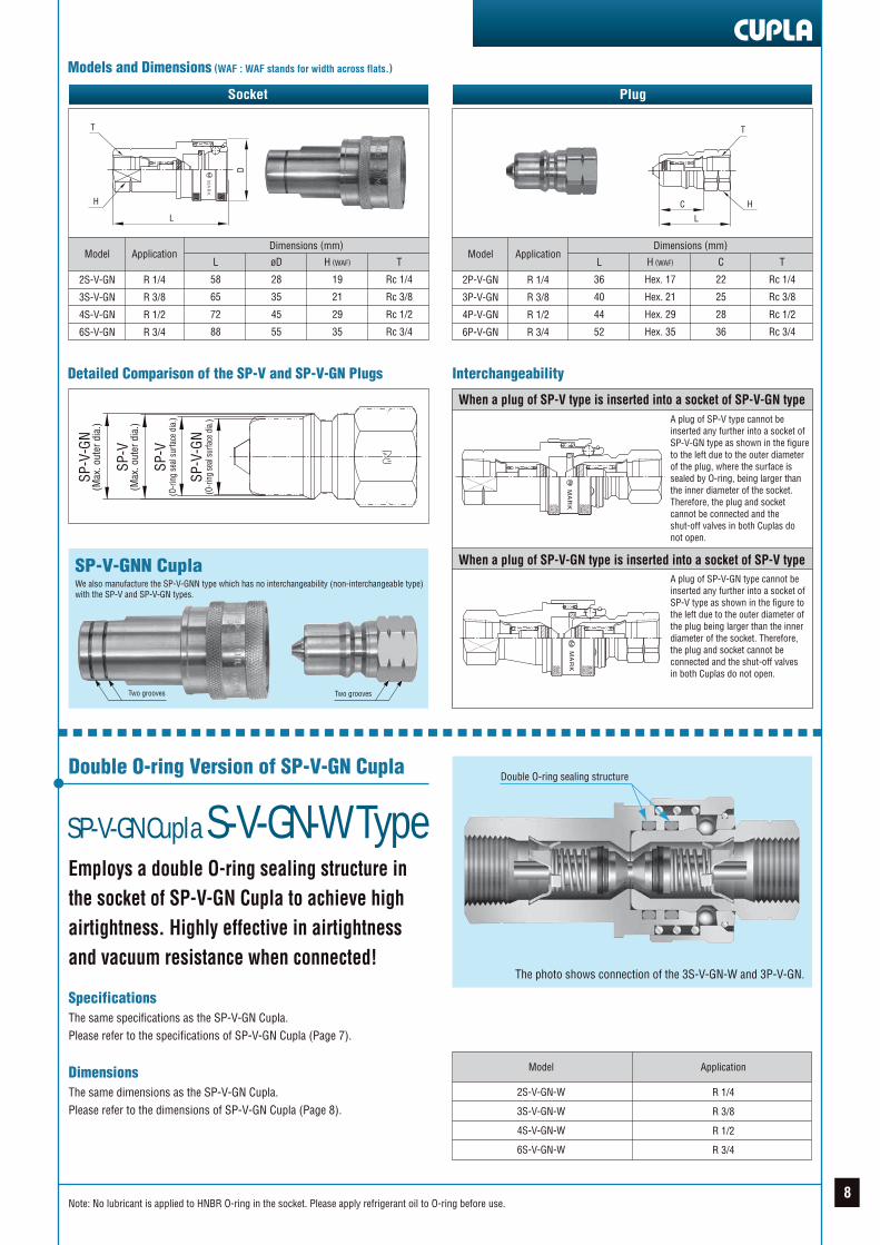
Double O-ring sealing structure
The photo shows connection of the 3S-V-W and 3P-V.
SP-V Cupla S-V-W TypeDouble O-ring Version of SP-V Cupla
Employs a double O-ring sealing structureto suit high airtightness.Highly effective in airtightness and vacuumresistance when connected!
SpecificationsThe same specifications as the SP-V Cupla.See the SP-V Cupla specifications.
DimensionsThe same dimensions as the SP-V Cupla.See the SP-V Cupla dimensions.
Models and Dimensions (WAF : WAF stands for width across flats.)
Application Example
PlugSocket
T
LD
T
C
L
MA
RK
Model ApplicationBrass
136
217
421
709
Stainlesssteel
127
197
393
658
L
58
65
72
88
øD
28
35
45
55
H (WAF)
19
21
29
35
T
Rc 1/4
Rc 3/8
Rc 1/2
Rc 3/4
2S-V
3S-V
4S-V
6S-V
R 1/4
R 3/8
R 1/2
R 3/4
Dimensions (mm)Mass (g)Model
Mass (g) Dimensions (mm)
Brass
39
67
123
211
Stainlesssteel
34
59
118
202
L
36
40
44
52
H (WAF)
Hex. 17
Hex. 21
Hex. 29
Hex. 35
C
22
25
28
36
T
Rc 1/4
Rc 3/8
Rc 1/2
Rc 3/4
2P-V
3P-V
4P-V
6P-V
R 1/4
R 3/8
R 1/2
R 3/4
Application
HH
6Note: No lubricant is applied to HNBR O-ring in the socket. Please apply refrigerant oil to O-ring before use.
SP-V-GN CuplaNon-interchangeable with SP-V Cupla
Prevents an operator from mixing updifferent refrigerants.
It may cause damage to equipment or products if differentrefrigeration oils are mixed together.• There is no interchangeability between SP-V Cupla and SP-V-GN Cupla to prevent accidental misconnection.• A socket of SP-V-GN Cupla has a different shape from that of SP-V Cupla and has a groove on the body. A plug of SP-V-GN Cupla also has a groove on the Nut to be distinguished from SP-V Cupla.
The photo shows connection of the3S-V-GN and 3P-V-GN.
A double sealingstructure employedfor improvedairtightness.
A double sealingstructure employedfor improvedairtightness.
Interchangeability (See page 8 for details.)
Different sizes are not interchangeable each other.Cannot be connected with the SP-V Cupla.
Flow Direction
Fluid may flow in either direction from plug or from socket side when coupled.
Automatic shut-off valves (airtightstructure) in both socket and plug.
Brass and stainless steel body materials are available.
Standard seal materials arefluoro rubber, HNBR and CRto suit air conditioner andrefrigerator production lines.
Blue HNBR O-ring isemployed for easyidentification to makereplacement of the socket’sO-ring without fail.
Comparison of External Appearance
One groove
Two groovesTwo grooves
One groove
OK
OK
OK
Socket
SP-V Cupla
SP-V-GN Cupla
SP-V-GNN Cupla
Plug
X indicates non-interchangeability.
Max. Tightening Torque (Nm {kgf •cm})1/4"
9 {92}
14 {143}
3/8"
12 {122}
22 {224}
1/2"
30 {306}
60 {612}
3/4"
50 {510}
90 {918}
Size (Thread)
Brass
Stainless steelTorque
Min. Cross-Sectional Area (mm2)2SP-V-GN
18
3SP-V-GN
38
4SP-V-GN
71
6SP-V-GN
110
Model
Min. cross-sectional area
2SP-V-GN
1.0
3SP-V-GN
2.4
4SP-V-GN
3.2
6SP-V-GN
10.5
Model
Volume of air admixture
Suitability for Vacuum (1.3 × 10⁻¹ Pa {1 × 10⁻³ mmHg})Plug only
Operational
When connected
Operational
Socket only
Operational
Admixture of Air on Connection (mL)
Specifications
Body material
Size (Thread)
Working pressure
Seal materialWorking temperature range
1/4", 3/8"
5.0
51
50
725
Seal material
Chloroprene rubber
Fluoro rubberHydrogenatednitrile rubber
1/2", 3/4"
3.0
31
30
435
Mark
CR (C308)
FKM (X-100)
HNBR (H708)
1/4", 3/8"
7.5
76
75
1090Working
temperature range
−20˚C to +80˚C−20˚C to +180˚C
−20˚C to +120˚C
1/2", 3/4"
4.5
46
45
653
Remarks
Standardmaterial
Stainless steelBrass
MPa
kgf/cm2
bar
PSI
Both socket and plug have unique vacuumresistant automatic shut-off valves inside.The valve prevents fluid spill out ondisconnection, and also has excellentvacuum resistance even after disconnection.
A unique straight guide isincorporated to stabilizevalve movement.
A unique straight guide isincorporated to stabilizevalve movement.
Flow Rate – Pressure Loss Characteristics[Test conditions] • Fluid : Water • Temperature : 24˚C ± 6˚C
1 10 100 1000
1.0 {10}
0.1 {1}
0.01 {0.1}
2SP-V-GN3SP-V-GN4SP-V-GN(Brass)
4SP-V-GN(Stainless steel)
6SP-V-GN(Stainless steel)
6SP-V-GN(Brass)
Flow rate in L/min
Pres
sure
loss
in M
Pa {k
gf/c
m2 }
7
R 1/4
R 3/8
R 1/2
R 3/4
ApplicationModel
2S-V-GN-W
3S-V-GN-W
4S-V-GN-W
6S-V-GN-W
Double O-ring sealing structure
The photo shows connection of the 3S-V-GN-W and 3P-V-GN.
SP-V-GN Cupla S-V-GN-W TypeDouble O-ring Version of SP-V-GN Cupla
Employs a double O-ring sealing structure inthe socket of SP-V-GN Cupla to achieve highairtightness. Highly effective in airtightnessand vacuum resistance when connected!
SpecificationsThe same specifications as the SP-V-GN Cupla.Please refer to the specifications of SP-V-GN Cupla (Page 7).
DimensionsThe same dimensions as the SP-V-GN Cupla.Please refer to the dimensions of SP-V-GN Cupla (Page 8).
Models and Dimensions (WAF : WAF stands for width across flats.)
Detailed Comparison of the SP-V and SP-V-GN Plugs Interchangeability
PlugSocket
Model ApplicationL
58
65
72
88
øD
28
35
45
55
H (WAF)
19
21
29
35
T
Rc 1/4
Rc 3/8
Rc 1/2
Rc 3/4
2S-V-GN
3S-V-GN
4S-V-GN
6S-V-GN
R 1/4
R 3/8
R 1/2
R 3/4
Dimensions (mm)Model
Dimensions (mm)
L
36
40
44
52
H (WAF)
Hex. 17
Hex. 21
Hex. 29
Hex. 35
C
22
25
28
36
T
Rc 1/4
Rc 3/8
Rc 1/2
Rc 3/4
2P-V-GN
3P-V-GN
4P-V-GN
6P-V-GN
R 1/4
R 3/8
R 1/2
R 3/4
Application
When a plug of SP-V type is inserted into a socket of SP-V-GN typeA plug of SP-V type cannot beinserted any further into a socket ofSP-V-GN type as shown in the figureto the left due to the outer diameterof the plug, where the surface issealed by O-ring, being larger thanthe inner diameter of the socket.Therefore, the plug and socketcannot be connected and theshut-off valves in both Cuplas donot open.
When a plug of SP-V-GN type is inserted into a socket of SP-V typeA plug of SP-V-GN type cannot beinserted any further into a socket ofSP-V type as shown in the figure tothe left due to the outer diameter ofthe plug being larger than the innerdiameter of the socket. Therefore,the plug and socket cannot beconnected and the shut-off valvesin both Cuplas do not open.
SP-V-GNN CuplaWe also manufacture the SP-V-GNN type which has no interchangeability (non-interchangeable type)with the SP-V and SP-V-GN types.
SP-V
-GN
(O-ri
ng se
al su
rface
dia.
)
SP-V
(O-ri
ng s
eal s
urfa
ce d
ia.)
SP-V
(Max
. out
er d
ia.)
SP-V
-GN
(Max
. out
er d
ia.)
MA
RK
MA
RK
Two groovesTwo grooves
MA
RK
T
L
D
T
C
L
H H
8Note: No lubricant is applied to HNBR O-ring in the socket. Please apply refrigerant oil to O-ring before use.
PCV Pipe CuplaFor Connection to Copper Pipes
Clamps directly on a straight copper pipeeliminating unnecessary welding or flaring.Double seal construction withstands avacuum of up to 1.3 × 10⁻¹ Pa.Suits for refrigerants that require highpressure.
• Withstands a vacuum of up to 1.3 x 10⁻¹ Pa {1 x 10⁻³ mmHg} (when connected) making it possible to be used in leak test, vacuum suction and refrigerant charge.• Select from three standard types of seal materials to be used with fluids for air conditioner and refrigerator production lines. Many models to suit various pipe sizes.• One lever operation simultaneously clamps and seals pipe. Double seal construction for tight fit on end and outside surface of pipe ensures excellent sealing and vacuum resistance.
The above photos are for PCV800.
InterchangeabilityA pipe can be connected to any model within the product group as shown inPage 10 regardless of the size (T) for mounting. A Cupla can be connected toany pipe with an odd shape provided that a pipe has appropriate outsidediameter and enough insertion length.
Clamping Mechanism
PCV400
3.8
PCV470
3.8
PCV500
3.8
PCV600
9.1
PCV630
9.1
PCV800
16.6
ModelMin. cross-
sectional area
PCV950
16.6
PCV1000
16.6
PCV1270-2
50.3
PCV1270-3
73.9
PCV1590-2
50.3
PCV1590-3
78.5
ModelMin. cross-
sectional area
Suitability for Vacuum (1.3 × 10⁻¹ Pa {1 × 10⁻³ mmHg})When connected to a pipe
Operational
Cupla only
-
SpecificationsModel
Copper pipe OD
Body material
Working pressure
Seal material
Working temperaturerange
PCV400
ø4.0
PCV470
ø4.76(3/16")
PCV500
ø5.0
PCV600
ø6.0
PCV630
ø6.35(1/4")
PCV800
ø8.0(5/16")
PCV950
ø9.52(3/8")
PCV1000
ø10.0
PCV1270
ø12.7(1/2")
PCV1590
ø15.88(5/8")
Seal material
Chloroprene rubber
Fluoro rubberHydrogenatednitrile rubber
Mark
CR (C308)
FKM (X-100)
HNBR (H708)
Workingtemperature range
−20˚C to +80˚C−20˚C to +180˚C
−20˚C to +120˚C
Remarks
Standardmaterial
Brass
4.5 MPa, 46 kgf/cm2, 45 bar, 653 PSI
Pipe Outside Diameter, Insert Length of Pipe into Cupla,and Minimum Thicknessof Pipe Wall (mm)
Please contact us for a pipe that has short insertion length or thin wall.
For exclusive use on straight copper pipes.Many models to cover various pipe sizes.
Double seal design for tight fit onboth end and outside of pipe.
Wide variations of end configurations; 1/4”, 3/8” and blind plug.
Standard seal materials fluoro rubber (FKM), hydrogenatednitrile rubber (HNBR) and chloroprene rubber (CR) to suitair conditioner and refrigerator production lines.
One lever operation simultaneously clamps and seals pipe.
Hydrogenated nitrile rubber (HNBR) is coloredin blue for easy recognition.
Max. Tightening Torque (Nm {kgf •cm})1/4"
9 {92}
3/8"
12 {122}
Size (Thread)
Torque
Min. Cross-Sectional Area (mm2)
Before clamping After clamping
When the lever is pushed down, the sleeve moves in the direction of the arrow, and atthe same time actuates the chucks to grip the copper pipe firmly and provide a tight seal.
ProductGroup
PCV400*
PCV470
PCV500*
PCV600
PCV630
PCV800
PCV950
PCV1000*
PCV1270
PCV1590
ø4.0
ø4.76 (3/16")
ø5.0
ø6.0
ø6.35 (1/4")
ø8.0 (5/16")
ø9.52 (3/8")
ø10.0
ø12.7 (1/2")
ø15.88 (5/8")
Pipe OD(Cu)
Items with asterisk (*) are made-to-order products.
Minimum Thickness of Pipe Wall
( t )
0.8 or more
1.0 or more
20.5
19
30
Insert Length of Pipe into Cupla
( )
t Cu
ChuckSeal
materials
SleeveCopper pipe
Lever
Push down
9
Models and Dimensions (WAF : WAF stands for width across flats.)
For mass with a plug, add (brass body) 2P-V: 39 g, 3P-V: 67 g, (stainless body) 2P-V: 34 g, or 3P-V: 59 g *Items with asterisk (*) are made-to-order products.
PCV Pipe Cupla with Plug
With 2P-V
Elbow types are also available.
With 3P-V
H
D
E
Cu
T
L
B
The above photo is for PCV800.
155
155
155
160
160
155
155
150
155
155
145
150
150
175
180
185
175
180
180
155
155
470
465
475
424
435
445
Rc 1/4
Rc 3/8
Rc 1/4
Rc 3/8
Blind plug
Rc 1/4
Rc 3/8
Rc 1/4
Rc 3/8
Blind plug
Rc 1/4
Rc 3/8
Blind plug
Rc 1/4
Rc 3/8
Blind plug
Rc 1/4
Rc 3/8
Blind plug
Rc 1/4
Rc 3/8
Rc 1/4
Rc 3/8
Blind plug
Rc 1/4
Rc 3/8
Blind plug
H (WAF)
Hex. 17
Hex. 19
Hex. 17
Hex. 19-
Hex. 17
Hex. 19
Hex. 17
Hex. 19-
Hex. 17
Hex. 19-
Hex. 17
Hex. 19-
Hex. 17
Hex. 19-
Hex. 17
Hex. 19
Hex. 24
Hex. 24-
Hex. 24
Hex. 24-
Product Group Application Mass(g)
ø4.0
Pipe OD(Cu)
Dimensions (mm)Model
PCV400-2
PCV400-3
PCV470-2
PCV470-3
PCV470-0
PCV500-2
PCV500-3
PCV600-2
PCV600-3
PCV600-0
PCV630-2
PCV630-3
PCV630-0
PCV800-2
PCV800-3
PCV800-0
PCV950-2
PCV950-3
PCV950-0
PCV1000-2
PCV1000-3
PCV1270-2
PCV1270-3
PCV1270-0
PCV1590-2
PCV1590-3
PCV1590-0
E
(32.5)
(32.5)
(32.5)
(32.5)
(32.5)
(35.5)
(35.5)
(35.5)
(45.0)
(45.0)
øD
22.2
22.2
22.2
22.2
22.2
24.8
24.8
24.8
34.8
34.8
ø4.76(3/16")
ø5.0
ø6.0
ø6.35(1/4")
ø8.0(5/16")
ø9.52(3/8")
ø12.7(1/2")
ø15.88(5/8")
ø10.0
PCV400*
PCV470
PCV500*
PCV600
PCV630
PCV800
PCV950
PCV1270
PCV1590
PCV1000*
øB
2.2
2.2
2.2
3.4
3.4
4.6
4.6
8.0
9.7
8.0
10.0
4.6
-
-
-
-
-
-
-
L(59)
(60)
(60)
(61)
(47)
(59)
(60)
(60)
(61)
(47)
(60)
(61)
(47)
(62)
(63)
(50)
(62)
(63)
(50)
(62)
(63)
(80)
(81)
(68)
(80)
(81)
(68)
T
R 1/4
R 3/8
R 1/4
R 3/8
-
R 1/4
R 3/8
R 1/4
R 3/8
-
R 1/4
R 3/8
-
R 1/4
R 3/8
-
R 1/4
R 3/8
-
R 1/4
R 3/8
R 1/4
R 3/8
-
R 1/4
R 3/8
-
• Specify the plug type (SP-V, SP-V-GN), the body material and seal material when ordering.• The Loctite (medium strength 242) is used as standard for the plug mounting adhesive. Should you require other adhesive or method such as a thread seal tape, please specify.
PCV Pipe Cupla with Plug (With Identification Ring)
With CR seal With HNBR seal
• When several refrigerants are used on the production line simultaneously, PCV Cupla with colored rings are available for visual recognition and to distinguish the seal material used.
PCV Pipe Cupla with a Water Drain Hole in the SleeveWhen a PCV Pipe Cupla is used in a water tank for leak test, a Cupla with awater drain hole in the Sleeve is available as a made-to-order product. Watercan be drained from theCupla easily.
Blue Ring Red Ring
10
Pipe Cupla PCVH TypeFor Connection to Copper Pipes
Lever shape has been changed for smoothoperation. Clamps directly on a straightcopper pipe eliminating unnecessarywelding or flaring. Double seal constructionwithstands a vacuum of up to 1.3 × 10⁻¹ Pa.
• The same specifications as the PCV Pipe Cupla. Please refer to the specifications of PCV Pipe Cupla (Page 9).• Withstands a vacuum of up to 1.3 x 10⁻¹ Pa {1 x 10⁻³ mmHg} (when connected) making it possible to be used in leak test, vacuum suction and refrigerant charge.• Select from three standard types of seal materials to be used with fluids for air conditioner and refrigerator production lines. Many models to suit various pipe sizes.• One lever operation simultaneously clamps and seals pipe. Double seal construction for tight fit on end and outside surface of pipe ensures excellent sealing and vacuum resistance.
The above photos are for PCVH800.
For exclusive use on straight copper pipes.Many models to cover various pipe sizes.
Double seal design for tight fit onboth end and outside of pipe.
Wide variations of end configurations; 1/4”, 3/8” and blind plug.
Standard seal materials fluoro rubber (FKM), hydrogenatednitrile rubber (HNBR) and chloroprene rubber (CR) to suitair conditioner and refrigerator production lines.
One lever operation simultaneously clamps and seals pipe.
Hydrogenated nitrile rubber (HNBR) is coloredin blue for easy recognition.
Curled
Triple Seal Structure
Pipe Cupla PCV-W TypeTriple Seal Version of PCV Pipe Cupla
A triple seal structure is employed, one atthe end of pipe and two on the outside ofpipe. Highly effective for airtightness andvacuum holding.
SpecificationsThe same specifications as the PCV Pipe Cupla.Please refer to the specifications of PCV Pipe Cupla (Page 9).
DimensionsThe same dimensions as the PCV Pipe Cupla.Please refer to the dimensions of PCV Pipe Cupla (Page 10).
Straight
Pipe Cupla PCVH Type with PlugThe PCVH type with plug is available on request as in the case ofPCV Pipe Cupla with plug. Please see Page 10.
Pipe Cupla PCVH Type with Plug (With Identification Ring)The PCVH Type with identification ring will be handled as in the case ofPCV Pipe Cupla with plug when requested. Please see page 10.
Lever shape has been changed from curled to straight for smooth operation.
11
Screw Cupla PCS Type
For Connection to Male Thread
By pushing the Screw Cupla direct to the malethread for connection improves operatingefficiency. Built-in Ball lock sleeve preventsaccidental disconnection, ensuring safe operation.
SpecificationsBody material
Counterpart Size
Working pressure
Seal material
Working temperature range
Seal material
Chloroprene rubberHydrogenatednitrile rubber
Mark
CR (C308)
HNBR (H708)
Working temperature range
−20˚C to +80˚C
−20˚C to +120˚C
Steel (Partly Stainless Steel and Brass)
For 7/16-20UNF, 5/8-18UNF, 3/4-16UNF,
7/8-14UNF, and 1-1/16-14UNS
3.0 MPa, 31 kgf/cm2, 30 bar, 345 PSI
Models and Dimensions (WAF : WAF stands for width across flats.)
DimensionsThe same dimensions as the Screw Cupla PCS type.Please refer to the dimensions of the Screw Cupla PCS type.
Screw Cupla PCS Type with PlugThe Screw Cupla PCS Type with Plug is available on request as in the case ofPCV Pipe Cupla with Plug including identification ring. Please refer to Page 10.
H
B
D
T
L
SpecificationsBody material
Counterpart Size
Working pressure
Seal materialWorking temperature range
Seal material
Chloroprene rubberHydrogenatednitrile rubber
Mark
CR (C308)
HNBR (H708)
Working temperature range
−20˚C to +80˚C
−20˚C to +120˚C
Steel (Partly Stainless Steel and Brass)
For 7/16-20UNF, 5/8-18UNF, 3/4-16UNF,
7/8-14UNF, and 11/16-14UNS
4.5 MPa, 46 kgf/cm2, 45 bar, 653 PSI
• Can be connected directly to UNF thread.
• The models listed below can be connected directly to UNF thread.• Simply push the Cupla onto the thread. The safety design ensures an instant and secure grip on the thread with the locking claws upon connection.• Sleeve lock mechanism prevents accidental disconnection.• Employing a three-terraced-shape lip packing enables more stable seal performance opposed to conventional packing and O-rings.• Hydrogenated nitrile rubber (HNBR) is colored in blue for easy recognition.• Time-consuming screw tightening work is eliminated, resulting in reduced connection time.
Suits for refrigerants that require high pressure.By pushing the Screw Cupla direct to the malethread for connection improves operating efficiency.
1.6
12Note: When considering using the Screw Cupla PCS Type or PCS-HP Type, refer to the outside diameter of the above Cuplas and verify if the Cupla can be connected to the UNF external thread without any interference.
Charge Cupla CS Type
For Charging Industrial Gases and Refrigerants
Min. Cross-Sectional Area (mm2)CS-2S-V × 2P-V
17
CS-3S-V × 3P-V
44
Model
Min. cross-sectional area
Combined Overall Length (mm)CS-2S-V × 2P-V
245.5
CS-3S-V × 3P-V
250.5
Model
Combined Overall Length
SpecificationsBody material
Size (Thread)
Working pressure
Seal materialWorking temperature range
Seal material
Chloroprene rubberHydrogenatednitrile rubber
Mark
CR (C308)
HNBR (H708)
Working temperature range
−20˚C to +80˚C
−20˚C to +120˚C
Stainless Steel (Partly Aluminum and Brass)
1/4"
3.0 MPa, 31 kgf/cm2, 30 bar, 435 PSI
H
L
T
T
Models and Dimensions
Socket
Model Connecting PlugDimensions (mm)
T
Rc 1/4
Rc 1/4
CS-2S-V
CS-3S-V
2P-V
3P-V
øH
42
42
L
232.5
235.5
How to Use
Connection to Plug
Disconnection of Plug
1
1
2
2
3
3
Pull the sleeve lever and push in the plug for connection.Raising the lever on the back end to 90° L-shape opensthe shut-off valves of the Charge Cupla and Plug to allowthe fluid to flow.
The plug can be easily disconnected by lowering the leveron the back end to the horizontal position and pulling thesleeve lever. The shut-off valves of the Charge Cupla andPlug close instantly to stop the fluid to flow.
Frequent connection and disconnection underpressure can be easily made with the uniquelever operation. Perfect for chargingrefrigerant, vacuum suction, and dischargingresidual pressure.• Equipped with an automatic shut-off valve. Fluid in the passage is prevented from flowing out when disconnected.• The Charge Cupla and Plug can be connected or disconnected even when the residual pressure remains. The shut-off valve can be opened or closed with the lever on the back end.• The safety design prevents the valve from opening even if the lever is operated without connecting to the plug.• The lever can be set to any position within the 360 degrees.• The CS type can be connected to the standard 2P-V and 3-PV Plugs. The CS-GN type is also available for the 2P-V-GN and 3P-V-GN Plugs on request.• Hydrogenated nitrile rubber (HNBR) is colored in blue for easy recognition.• The Charge Cupla that employs a double O-Ring seal structure for high airtightness is also available on request.
A general rule for identification
• A Charge Cupla with CR seal : The body and grip are coated with blue colored anodic oxidized alumina.• A Charge Cupla with HNBR seal : The body and grip are coated with red colored anodic oxidized alumina.• Please contact us should you require any other color.
13Note: No lubricant is applied to HNBR O-ring in the socket. Please apply refrigerant oil to O-ring before use.
Charge Cupla CS-HP Type
Suits for Refrigerants That Require High Pressure
Min. Cross-Sectional Area (mm2)CS-2S-V-HP × 2P-V
17
CS-4S-V-HP × 4P-V
71
Model
Min. cross-sectional area
Combined Overall Length (mm)CS-2S-V-HP × 2P-V
263
CS-3S-V-HP × 3P-V
44
CS-3S-V-HP × 3P-V
267
CS-4S-V-HP × 4P-V
297
Model
Combined Overall Length
SpecificationsBody material
Size (Thread)
Working pressure
Seal materialWorking temperature range
Seal material
Chloroprene rubberHydrogenatednitrile rubber
Mark
CR (C308)
HNBR (H708)
Working temperature range
−20˚C to +80˚C
−20˚C to +120˚C
Stainless Steel (Partly Aluminum and Brass)
1/4", 1/2"
4.5 MPa, 46 kgf/cm2, 45 bar, 653 PSI
Models and Dimensions
Socket
Model Connecting PlugDimensions (mm)
T
Rc 1/4
Rc 1/4
Rc 1/2
CS-2S-V-HP
CS-3S-V-HP
CS-4S-V-HP
2P-V
3P-V
4P-V
øH
43
43
50
L
250
252
273
How to Use
Connection to Plug
Disconnection of PlugThe plug can be easily disconnected by lowering the leveron the back end to the horizontal position and pulling thesleeve lever. The shut-off valves of the Charge Cupla andPlug close instantly to stop the fluid to flow.
1
2
3
1
2
3
Pull the sleeve lever and push in the plug for connection.Raising the lever on the back end to 90° L-shape opensthe shut-off valves of the Charge Cupla and Plug to allowthe fluid to flow.
H
L
T
T
M A
R K
Suits for refrigerants that require high pressure.High pressure version of the CS type. Frequentconnection and disconnection under pressurecan be easily made with the unique leveroperation.• Equipped with an automatic shut-off valve. Fluid in the passage is prevented from flowing out when disconnected.• The Charge Cupla and Plug can be connected or disconnected even when the residual pressure remains. The shut-off valve can be opened or closed with the lever on the back end.• The safety design prevents the valve from opening even if the lever is operated without connecting to the plug.• The lever can be set to any position within the 360 degrees.• The CS-HP type can be connected to the standard 2P-V, 3P-V, and 4P-V Plugs. The CS-HP-GN type is also available for the 2P-V-GN, 3P-V-GN, and 4P-V-GN Plugs on request.• The Charge Cupla that employs a double O-Ring seal structure for high airtightness is also available on request.
A general rule for identification
• A Charge Cupla with CR seal : The body and grip are coated with blue colored anodic oxidized alumina.• A Charge Cupla with HNBR seal : The body and grip are coated with red colored anodic oxidized alumina.• Please contact us should you require any other color.
14Note: No lubricant is applied to HNBR O-ring in the socket. Please apply refrigerant oil to O-ring before use.
1
1
2
2
2
1
3
Charge CuplaCNR Type/LRP Type
For charging Industrial Gases and Refrigerants
How to Use
Models and Dimensions (WAF : WAF stands for width across flats.)
Socket
Model ConnectingPlug L
123
øD
33
L1
96
H (WAF)
17
W
(42)
T
Rc 1/4LRP-2S-V 2P-V
Dimensions (mm)Model Connecting
Plug L
135
161
øD
35
45
L1
121
145
W
(48)
(54)
H (WAF)
24
32
T
Rc 3/8
Rc 1/2
CNR-3S
CNR-4S
3P-V
4P-V
Dimensions (mm)
Connection to PlugPull the sleeve on the Charge Cupla and insert the plug into the Charge Cupla foreasy connection.
Lowering the lever opensthe valve to allowfluid flow.
Disconnection of PlugLifting the lever discharges the remaining pressure between the valves in the Charge Cuplaand plug. The plug can then be easily disconnected by pulling the sleeve on the Charge Cupla.Upon disconnection the valvesin both sides closethe flow passageinstantly to preventfluid from flowing out.
T
D
L1
L
W
Min. Cross-Sectional Area (mm2)CNR-3S × 3P-V
44
LRP-2S × 2P-V
17
Model
Min. cross-sectional area
Combined Overall Length (mm)CNR-3S × 3P-V
136
CNR-4S × 4P-V
62
CNR-4S × 4P-V
161
LRP-2S × 2P-V
110
Model
Combined Overall Length
SpecificationsBody material
Size (Thread)
Working pressure
Seal materialWorking temperature range
Seal material
Chloroprene rubberHydrogenatednitrile rubber
Mark
CR (C308)
HNBR (H708)
Working temperature range
−20˚C to +80˚C
−20˚C to +120˚C
Stainless Steel (Partly Aluminum and Brass)
1/4", 3/8", 1/2"
4.5 MPa, 46 kgf/cm2, 45 bar, 653 PSI
CNR Type LRP Type
D
L1
L
T
W
CNR Type
LRP Type
Easy disconnection from the plug by lifting thelever to discharge the residual pressure.Perfect for charging refrigerant, vacuumsuction, and connection/disconnection underresidual pressure.• Equipped with an automatic shut-off valve. Fluid in the passage is prevented from flowing out when disconnected.• The Charge Cupla and Plug can be connected or disconnected even when the residual pressure remains. The shut-off valve can be opened or closed with the lever on the back.• Employs a double O-ring sealing structure for high air-tightness upon connection.• The safety design prevents the valve from opening even if the lever is operated without connecting to the plug.• Easy disconnection from the plug by lifting the lever to discharge the residual pressure after charging is complete.• The CNR type can be connected to the standard 3P-V and 4-PV Plugs, and the LRP type to the standard 2P-V Plug. The CNR-GN type is also available for the 3P-V-GN and 4P-V-GN Plugs, and LRP-GN type for the 2P-V-GN Plug on request.• Hydrogenated nitrile rubber (HNBR) is colored in blue for easy recognition.
HH
Prior to connecting/disconnecting the plug, reduce the fluid pressure below 1.0 MPa. The lever will springback when pulled back with pressure remaining inside. Be careful not to get your fingers caught in the Cupla.
15Note: No lubricant is applied to HNBR O-ring in the socket. Please apply refrigerant oil to O-ring before use.
2
1
1
2
2
1
3
For Charging Industrial Gases and Refrigerants
Min. Cross-Sectional Area (mm2)Model
Min. cross-sectional area
Combined Overall Length (mm)
CNA-3S-V × CNA-3P-V
31.5
CNA-3S-V × CNA-3P-V
111
Model
Combined Overall Length
SpecificationsBody material
Size (Thread)
Working pressure
Seal materialWorking temperature range
Seal materialHydrogenatednitrile rubber
Mark
HNBR (H708)
Working temperature range
−20˚C to +120˚C
Stainless Steel (Partly Aluminum and Brass)
3/8"
3.0 MPa, 31 kgf/cm2, 30 bar, 435 PSI
How to Use
Models and Dimensions (WAF : WAF stands for width across flats.)
PlugSocket
Model ApplicationL
114
L1
103
øD
38
W
(48)
H (WAF)
23
T
Rc 3/8CNA-3S-V R 3/8
Dimensions (mm)Model
Dimensions (mm)
L
43
H (WAF)
Hex. 23
T
Rc 3/8CNA-3P-V R 3/8
Application
Connection to PlugPull the sleeve on the Charge Cupla and insert the plug for easy connection.Lowering the lever opens the valve to allow fluid flow.
Disconnection of PlugThe plug can be easily disconnected by lifting the lever and pulling the sleeve onthe Charge Cupla. Upon disconnection the valves in both sides close the flowpassage instantly to prevent fluid from flowing out.
T
H
L
T
W D
L
L1
Airless Charge CuplaCNA TypeThe Airless valve structure minimizes airingress on connection and fluid spillage ondisconnection. Perfect for charging refrigerant,vacuum suction, and connection/disconnectionunder residual pressure.• A special airless valve structure is employed in both socket and plug. This minimizes air ingress on connection and fluid spillage on disconnection. (CNA-GN Type is also available on request.)• The Airless Charge Cupla and Plug can be connected or disconnected even when the residual pressure remains. The airless shut-off valve can be opened or closed with the lever on the back.• The safety design prevents the valve from opening even if the lever is operated without connecting to the plug.
H
16
Auto Cupla ACV Type
Air-driven Mechanism for Plug Disconnection
Automatic Plug Disconnection Type.Contributes to energy and labor saving on theproduction line.Simply push the Plug into the Auto Cupla forconnection.
• Air-driven mechanism is employed in the Auto Cupla to disconnect the plug. For an emergency, manual disconnection is possible. An automatic shut-off valve in the Auto Cupla prevents fluid from spilling on disconnection.• The ACV type can be connected to the standard 2P-V and 3P-V Plugs. The ACV-GN type is also available for the 2P-V-GN and 3P-V-GN Plugs on request.• Hydrogenated nitrile rubber (HNBR) is colored in blue for easy recognition.
SpecificationsBody material
Size (Thread)
Working pressure
Seal materialWorking temperature range
Maximum Cupla InnerPressure for Air Operation
Seal material
Chloroprene rubber
Hydrogenatednitrile rubber
Mark
CR (C308)
HNBR (H708)
Working temperature range
−20˚C to +80˚C
Nitrile rubber NBR (SG)
When DisconnectingPlug 1.0 MPa, 10 kgf/cm2, 10 bar, 142 PSI
−20˚C to +80˚C
−20˚C to +120˚C
Stainless Steel (Partly Aluminum and Brass)
1/4", 3/8"
3.0 MPa, 31 kgf/cm2, 30 bar, 435 PSI
A general rule for identification
• An Auto Cupla with CR seal: The body is coated with blue colored anodic oxidized alumina.• An Auto Cupla with HNBR seal: The body is coated with red colored anodic oxidized alumina.• Please contact us should you require any other color.
Models and Dimensions (WAF : WAF stands for width across flats.)
Socket
Model Connecting PlugDimensions (mm)
T
Rc 1/8
Rc 1/8
T1
Rc 1/4
Rc 3/8
ACV-2S
ACV-3S
2P-V
3P-V
øD
42
45
L
100
96
H (WAF)
19
21
How to Use
Connection to Plug
L
D
T
H
T1
Auto Cupla is connectedto Plug
Simply push the plug into the Auto Cupla for connection.
Upon connection, the valves in the Auto Cupla and plug open instantly to allowthe fluid flow.
Disconnection of PlugPrior to disconnecting the plug, reduce the fluid pressure below 1.0 MPa(10 kgf/cm2). The plug can be automatically disconnected by applying airpressure of 0.5 to 0.6 MPa (5 to 6 kgf/cm2) to section A.
Disconnection of Plug for an emergencyThe plug can be easily disconnected by pulling the front side sleeve in thedirection of the arrow.
Section A
17Note: No lubricant is applied to HNBR O-ring in the socket. Please apply refrigerant oil to O-ring before use.
Auto Cupla ACV-HP Type
Air-driven Mechanism for Plug Disconnection (High Pressure Version)
Suits for refrigerants that require high pressure.High pressure version of the ACV type.Automatic Plug Disconnection Type.Contributes to energy and labor saving on theproduction line.
• Simply push the plug into the Auto Cupla for connection.• Air-driven mechanism is employed in the Auto Cupla to disconnect the plug. For an emergency, manual disconnection is possible.• An automatic shut-off valve in the Auto Cupla prevents fluid from spilling on disconnection.• The ACV-HP type can be connected to the standard 2P-V and 3P-V Plugs. The ACV-HP-GN type is also available for the 2P-V-GN and 3P-V-GN Plugs on request.
A general rule for identification
• An Auto Cupla with CR seal: The body is coated with blue colored anodic oxidized alumina.• An Auto Cupla with HNBR seal: The body is coated with red colored anodic oxidized alumina.• Please contact us should you require any other color.
Models and Dimensions (WAF : WAF stands for width across flats.)
Socket
Model Connecting PlugDimensions (mm)
T
Rc 1/8
Rc 1/8
T1
Rc 1/4
Rc 3/8
ACV-2S-HP
ACV-3S-HP
2P-V
3P-V
øD
42
45
L
100
96
H (WAF)
19
21
How to Use
Connection to Plug
Auto Cupla is connectedto Plug
Simply push the plug into the Auto Cupla for connection.
Upon connection, the valve in the Auto Cupla and plug open instantly to allowthe fluid flow.
Disconnection of PlugPrior to disconnecting the plug, reduce the fluid pressure below 1.0 MPa(10 kgf/cm2). The plug can be automatically disconnected by applying airpressure of 0.5 to 0.6 MPa (5 to 6 kgf/cm2) to section A.
Disconnection of Plug for an emergencyThe plug can be easily disconnected by pulling the front side sleeve in thedirection of the arrow.
SpecificationsBody material
Size (Thread)
Working pressure
Seal materialWorking temperature range
Maximum Cupla InnerPressure for Air Operation
Seal material
Chloroprene rubber
Hydrogenatednitrile rubber
Mark
CR (C308)
HNBR (H708)
Working temperature range
−20˚C to +80˚C
When DisconnectingPlug
1.0 MPa, 10 kgf/cm2, 10 bar, 142 PSI
−20˚C to +120˚C
Stainless Steel (Partly Aluminum and Brass)
1/4", 3/8"
4.5 MPa, 46 kgf/cm2, 45 bar, 653 PSI
Section A
L
D
T
H
T1
18Note: No lubricant is applied to HNBR O-ring in the socket. Please apply refrigerant oil to O-ring before use.
Auto Cupla AC Type
Air-driven Mechanism for Valve Opening / Closing and Plug Disconnection
Auto Cupla automatically opens and closes thevalve, and disconnects the plug.Contributes to energy and labor saving on theproduction line.• Air-driven mechanism is employed in the Auto Cupla to connect and disconnect the plug and to open and close the valve.• An automatic shut-off valve in the Auto Cupla prevents fluid from spilling on disconnection.• The unique air-driven mechanism reduces the load when the plug is connected to the Auto Cupla.• The Auto Cupla and Plug can be connected or disconnected even when the residual pressure remains.• The safety design prevents the valve from opening even if the valve is operated to open with air-driven mechanism without connecting to the plug.• The AC type can be connected to the standard 2P-V and 3P-V Plugs. The AC-GN type is also available for the 2P-V-GN and 3P-V-GN Plugs on request.• Hydrogenated nitrile rubber (HNBR) is colored in blue for easy recognition.
SpecificationsBody material
Size (Thread)
Working pressure
Seal materialWorking temperature range
Maximum Cupla InnerPressure for Air Operation
Seal material
Chloroprene rubber
Hydrogenatednitrile rubber
Mark
CR (C308)
HNBR (H708)
Working temperature range
−20˚C to +80˚C
Nitrile rubber NBR (SG)
When opening and closing the valve
When disconnecting the plug
1.0 MPa, 10 kgf/cm2, 10 bar, 145 PSI
1.0 MPa, 10 kgf/cm2, 10 bar, 145 PSI
−20˚C to +80˚C
−20˚C to +120˚C
Stainless Steel (Partly Aluminum and Brass)
1/4", 3/8"
3.0 MPa, 31 kgf/cm2, 30 bar, 435 PSI
A general rule for identification
• An Auto Cupla with CR or NBR seal: The body is coated with blue colored anodic oxidized alumina.• An Auto Cupla with HNBR seal: The body is coated with red colored anodic oxidized alumina.• Please contact us should you require any other color.
Models and Dimensions (WAF : WAF stands for width across flats.)
Socket
Model Connecting PlugDimensions (mm)
T2
Rc 1/8
Rc 1/8
T3
Rc 1/8
Rc 1/8
T1
Rc 1/4
Rc 3/8
AC-2S
AC-3S
2P-V
3P-V
øD
44
55
L
155
173
H (WAF)
Hex. 17
Hex. 21
How to Use
Connection to Plug
Auto Cupla is connectedto Plug
The balls in the Auto Cupla become loose by applying air pressure of 0.5 to0.6 MPa (5 to 6 kgf/cm2) to section A. The plug can then be easily inserted.Completely inserting the plug into the Auto Cupla and reducing the pressureon section A to 0 MPa will lock the Auto Cupla and plug and complete theconnection. (* The valve is not open in this state.)
Opening and Closing the Valve
Disconnection of PlugPrior to disconnecting the plug, reduce the fluid pressure below 1.0 MPa(10 kgf/cm2). The plug can be disconnected by applying air pressure of 0.5 to0.6 MPa (5 to 6 kgf/cm2) to section A after reducing the air pressure on sectionB to 0 MPa.
L
D
T3(Air port for disconnection with the plug)
T2(Air port for valve opening and closing)
T1
H
Section A: Compressed Air
Section B: Compressed Air
Section A: Compressed AirSection B Pressure: 0 MPa
Section B Pressure: 0 MPa
Prior to operating the valve, reduce the fluid pressure below 1.0 MPa(10 kgf/cm2). The valves in theAuto Cupla and plug open by applyingair pressure of 0.5 to 0.6 MPa(5 to 6 kgf/cm2) to section B.By reducing the air pressureon section B to 0 MPa,the valves in the Auto Cuplaand plug close therebystopping the fluid flow.
The ACS type, which can be connected to the plugby simply pushing the plug into the Auto Cupla,is also available on request.
Auto Cupla ACS Type
19Note: No lubricant is applied to HNBR O-ring in the socket. Please apply refrigerant oil to O-ring before use.
Suits for refrigerants that require high pressure.High pressure version of the AC type.Auto Cupla automatically opens and closes thevalve and disconnects the plug.Contributes to energy and labor saving on theproduction line.
• Air-driven mechanism is employed in the Auto Cupla to connect and disconnect the plug and to open and close the valve.• An automatic shut-off valve in the Auto Cupla prevents fluid from spilling on disconnection.• The unique air-driven mechanism reduces the load when the plug is connected to the Auto Cupla.• The Auto Cupla and Plug can be connected or disconnected even when the residual pressure remains.• The safety design prevents the valve from opening even if the valve is operated to open with air-driven mechanism without connecting to the plug.• The AC-HP type can be connected to the standard 3P-V Plug. The AC-HP-GN type is also available for the 3P-V-GN Plug on request.
SpecificationsBody material
Size (Thread)
Working pressure
Seal materialWorking temperature range
Maximum Cupla InnerPressure for Air Operation
Seal materialHydrogenatednitrile rubber
Mark
HNBR (H708)
Working temperature range
When opening and closing the valve
When disconnecting the plug
1.0 MPa, 10 kgf/cm2, 10 bar, 145 PSI
1.0 MPa, 10 kgf/cm2, 10 bar, 145 PSI
−20˚C to +120˚C
Stainless Steel (Partly Aluminum and Brass)
3/8"
4.5 MPa, 46 kgf/cm2, 45 bar, 653 PSI
Models and Dimensions (WAF : WAF stands for width across flats.)
Socket
Model Connecting PlugDimensions (mm)
T2
Rc 1/8
T3
Rc 1/8
T1
Rc 3/8AC-3S-HP 3P-V
øD
65
L
176
H (WAF)
Hex. 21
How to Use
Connection to Plug
Auto Cupla is connectedto Plug
The balls in the Auto Cupla become loose by applying air pressure of 0.5 to0.6 MPa (5 to 6 kgf/cm2) to section A. The plug can then be easily inserted.Completely inserting the plug into the Auto Cupla and reducing the pressureon section A to 0 MPa will lock the Auto Cupla and plug and complete theconnection. (* The valve is not open in this state.)
Opening and Closing the Valve
Disconnection of PlugPrior to disconnecting the plug, reduce the fluid pressure below 1.0 MPa(10 kgf/cm2). The plug can be disconnected by applying air pressure of 0.5 to0.6 MPa (5 to 6 kgf/cm2) to section A after reducing the air pressure on sectionB to 0 MPa.
Prior to operating the valve, reduce the fluid pressure below 1.0 MPa(10 kgf/cm2). The valves in the Auto Cupla and plug open by applying airpressure of 0.5 to 0.6 MPa (5 to 6 kgf/cm2) to section B. By reducing the airpressure on section B to0 MPa, the valves in theAuto Cupla and plug closethereby stoppingthe fluid flow.
MA
RK
L
D
T3(Air port for disconnection with the plug)
T2(Air port for valve opening and closing)
T1
H
20Note: No lubricant is applied to HNBR O-ring in the socket. Please apply refrigerant oil to O-ring before use.
Screw Cupla NCF Type
Screw-on Type Cupla
SpecificationsIdentification of the seal material by the Appearance of the Nut
Three-terraced-shape lip packing
Body material
Size
Working pressure
Seal materialWorking temperature range
Seal material
Chloroprene rubberHydrogenatednitrile rubber
Mark
CR (C308)
HNBR (H708)
Working temperature range
−20˚C to +80˚C
−20˚C to +120˚C
Stainless steel
For unified thread
4.5 MPa, 46 kgf/cm2, 45 bar, 653 PSI
Models and Dimensions (WAF : WAF stands for width across flats.)When considering using the Screw Cupla NCF Type, refer to the external dimensions of the Cuplas below and verify if the Cupla can be connected to the unified external threads without any interference.
Hydrogenated nitrile rubber (HNBR) is colored in blue for easy recognition.
Three-terraced-shapelip packing
Screw Cupla NCF Type with Plug
With 2P-V
With 3P-V
Elbow types are also available.
• Specify the plug type (SP-V, SP-V-GN), the body material and seal material when ordering.• The Loctite (medium strength 242) is used as standard for the plug mounting adhesive. Should you require other adhesive or method such as thread seal tape, please specify.
NCF Cupla with Plug (With Identification Ring)
With CR seal With HNBR seal
• When several refrigerants are used on the production line simultaneously, Screw Cupla with colored rings are available for visual recognition and to distinguish the seal material used.
Blue Ring Red Ring
tT
HL
B D
T2R
B C
F E A
Unified thread: Pursuant to JIS B 8607
Screws on to the male unified thread easily.Made up of the nut and body.The bearing in the Screw Cupla makes rotationof the nut smooth and reduces damage to thethree-terraced-shape lip packing.
• Employing a three-terraced-shape lip packing enables more stable seal performance opposed to conventional packing and O-rings.• Withstands a vacuum of up to 1.3 x 10⁻¹Pa (1 x 10⁻³ mmHg) (when connected) making it possible to be used in leak test, vacuum suction and refrigerant charge.• Select from two standard types of seal materials to be used with fluids for air conditioner and refrigerator production lines. Many models available to suit various thread sizes.• The nut shape is changed for visual recognition of the seal material used in the Screw Cupla.
External threadfor connection
(t)
1.6
21* Following types are available on request: Long adapter type, 45 degree elbow type, types with round knurled nut, small outer diameter nut or O-ring seal.
The Pipe Cuplas have been developed for production lines of refrigeration, air conditioning,and automotive industries, and for maintenance services for these products.Connecting the Cuplas directly to various types of pipes greatly contributes
to enhance productivity, labor-saving, and automation in the production lines.
Pipe Cupla Series
Connects to various types of pipes and fittings (see the examples below)
• All Pipe Cuplas are made-to-order products that will be designed based on the specifications of customer’s work presented by the customer.• When considering to use Pipe Cuplas, please let us know the following points: pressure, name of fluid, end configuration of Cupla, usage condition, and application, etc.• All Pipe Cuplas are designed based on the specifications of customer’s work. Therefore, it is essential for us to receive the drawing of the work and the work sample from the customer.
Applications
When Considering to Use Pipe Cuplas
Swaged Pipes
Expanded Pipes
Flared PipesStraight Pipes
Bulged Pipes for RadiatorsBulged Pipes
for Fuel for Engines
Spool Pipes for Fuel
Bulged Pipes for Heaters
Hose Barbs
Flare Nuts
Unified Thread Fittings
Union Adapters
For Charging Work
For Pressure Resistance Test
For Leak Test
For Vacuum Suction Test
For Running Test
22
Pipe Cupla PCHS Type
Chuck Lock System for Expanded Pipesand Bulged Pipes
A special chuck lock system is employed toreduce lock scratches and improve pressureresistance.Suits for high pressure use.
• Simply push pipes into the Pipe Cupla for connection.• Locking the outer surface of pipe with the special collet chuck reduces lock scratches and improves pressure resistance.• A model with sleeve stopper mechanism is also available on request. It prevents accidental disconnection after connecting the Pipe Cupla to pipes.
Pipe Cupla PCB Type
For Expanded Pipes
Suits for connection and disconnection withexpanded pipes and spool pipes.Easy to handle with the ball lock system usingsleeve operation.
• Connects directly to pipes.• Employs a ball lock system to grip on the outer surface of pipe.• A model equipped with automatic shut-off valve or sleeve lock mechanism to prevent accidental disconnection is available on request.
ApplicationsCharging WorkPressure Resistance TestLeak Test
ApplicationsCharging WorkPressure Resistance TestLeak TestVacuum Suction Test
23
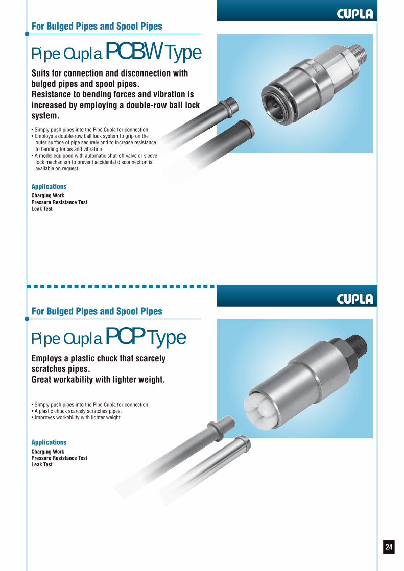
Pipe Cupla PCBW Type
For Bulged Pipes and Spool Pipes
Suits for connection and disconnection withbulged pipes and spool pipes.Resistance to bending forces and vibration isincreased by employing a double-row ball locksystem.• Simply push pipes into the Pipe Cupla for connection.• Employs a double-row ball lock system to grip on the outer surface of pipe securely and to increase resistance to bending forces and vibration.• A model equipped with automatic shut-off valve or sleeve lock mechanism to prevent accidental disconnection is available on request.
Pipe Cupla PCP Type
For Bulged Pipes and Spool Pipes
Employs a plastic chuck that scarcelyscratches pipes.Great workability with lighter weight.
• Simply push pipes into the Pipe Cupla for connection.• A plastic chuck scarcely scratches pipes.• Improves workability with lighter weight.
ApplicationsCharging WorkPressure Resistance TestLeak Test
ApplicationsCharging WorkPressure Resistance TestLeak Test
24
Pipe Cupla PCBL Type
For Straight Pipes
Pipe Cupla PCLB Type
For Straight Pipes
ApplicationsCharging WorkPressure Resistance TestLeak TestVacuum Suction Test
ApplicationsCharging WorkPressure Resistance TestLeak Test
Suits for connection and disconnection withstraight pipes.Employs a ball lock system to grip on the outersurface of pipe. Improved connection anddisconnection with lever operation.
• Connects directly to straight pipes.• A ball lock system grips on the outer surface of pipe.• Employs a lever operation system for easy connection and disconnection.• Employs an aluminum body to lighten the weight and to improve workability.• Particularly suitable for refrigerator assembly lines.
Suits for connection and disconnection withstraight pipes.Employs a ball lock system to grip on the outersurface of pipe.One-handed lever operation facilitates easyconnection and disconnection with pipes.
• Connects directly to straight pipes.• A ball lock system grips on the outer surface of pipe.
25
PCV Type Cuplawith Residual PressureRelease Device
For Straight Pipes
Equipped with the residual pressure releasedevice. Lever operation releases the residualpressure for easy disconnection.
• Made up of PCV Type Cupla and the residual pressure release device.• Raising the lever of the residual pressure release device releases the residual pressure for easy pipe disconnection.• Suits for refrigerants that require high pressure.
Pipe Cupla PCB Type
For Pipes with Fittings
Suits for connection and disconnection withpipe fittings.A ball lock system grips on the rear of the hex.nut of pipe fitting upon connection.
• Connects directly to pipe fittings.• Simply push pipes into the Pipe Cupla for connection. The balls in the Pipe Cupla grip on the rear of the hex. nut of pipe fitting upon connection.
ApplicationsCharging WorkPressure Resistance TestLeak Test
ApplicationsCharging WorkPressure Resistance TestLeak Test
Close
Open (Residual pressure release)
26
Pipe Cupla PCW Type
For Straight Pipes and Pipes with Blind Rubber Plugs
Suits for connection and disconnection withstraight pipes and pipes with blind rubber plugs.Frequent connection and disconnection can beeasily made with the unique lever operation.
• Connects directly to pipes.• Unique lock design on pipes allows some slight variations in pipe dimensions.
Pipe Cupla PCA Type
For Large Diameter Straight Pipes
• Connects directly to large diameter straight pipes.• Employs a special chuck lock system to grip on the outer surface of pipe.
ApplicationsCharging WorkPressure Resistance TestLeak Test
ApplicationsCharging WorkPressure Resistance TestLeak TestVacuum Suction Test
Suits for connection and disconnection withlarge diameter straight pipes.Employs a special chuck lock system.High pressure resistant version is also availableon request.
27
Pipe Cupla PCD Type
For Special Pipes
Simply push the Pipe Cuplaonto pipe fittings.Unique locking mechanismprovides outstanding pressureresistance and air-tightness.
• Applicable to pipes with a wide variety of fittings.• A special clamp locks the outer surface of pipe.• A model equipped with sleeve lock mechanism to prevent accidental disconnection is available on request.
Pipe Cupla PCH Type
High Pressure Type for Spool Pipes
Suits for connection and disconnection withspool pipes.A special chuck lock system reduces lockscratches and improves pressure resistance.
• Simply push spool pipes into the Pipe Cupla for connection.• A special chuck lock system is employed to reduce lock scratches and improve pressure resistance.• A model equipped with sleeve lock mechanism to prevent accidental disconnection is available on request.
ApplicationsCharging workPressure Resistance TestLeak TestVacuum Suction Test
ApplicationsCharging WorkPressure Resistance TestLeak Test
28
Screw Cupla PCSI Type
Screw-in Type Cupla
By pushing the Screw Cupla direct to thefemale thread for connection improvesoperating efficiency.
• Connects directly to the female thread.• Simply push the Screw Cupla into the female thread. The safety design ensures an instant and secure grip on the thread with the locking claws upon connection.• Time-consuming screw tightening work is eliminated, resulting in reduced connection time.
Pipe Cupla PCBI Type
For Locking at the Leading End of Workpiece from the Inside
Employs balls to lock at the leading end ofworkpiece from the inside.Greatly improves workability.
• Simply push the back end of the Pipe Cupla toward the workpiece for connection. The balls in the Pipe Cupla lock at the leading end of the workpiece from the inside upon connection.• Internal pressure is utilized to enhance the sealing performance between the Pipe Cupla and workpiece.• Time-consuming connection work is eliminated.
ApplicationsCharging WorkPressure Resistance TestLeak Test
ApplicationsCharging WorkPressure Resistance TestLeak Test
29
Pipe Cupla PCI Type
For Locking at the Leading End of Workpiece from the Inside
Employs chucks to lock at the leading end ofworkpiece from the inside.Greatly improves workability.
• Simply push the back end of the Pipe Cupla toward the workpiece for connection. The chucks in the Pipe Cupla securely lock at the leading end of the workpiece from the inside upon connection.• Internal pressure is utilized to enhance the sealing performance between the Pipe Cupla and workpiece.• Time-consuming connection work is eliminated.
Pipe Cupla PCIF Type
For Pipe Inner Wall Lock
Employs chucks to grip on the inner wall of pipe.Suitable for applications with a small amountof clearance.
• Moving the lever of the Pipe Cupla horizontally completes connection with the pipe.• Pushing the rod shaped part of the Pipe Cupla into the inside of pipe and moving the lever horizontally activates the chucks to grip on the inner wall of pipe securely.• Lever operation seals the fluid passage at the inner wall and the leading end of pipe.• Time-consuming connection work is eliminated.
ApplicationsCharging WorkPressure Resistance TestLeak Test
ApplicationsCharging WorkPressure Resistance TestLeak TestVacuum Suction Test
A PCIF type shown below is available on request.
30
AUTO Cupla APCB Type
For Automatic Pipe Disconnection
Automatic Pipe Disconnection Type.Contributes to energy and labor saving on theproduction line.
• Simply push pipes into the Auto Cupla for connection.• Air-driven mechanism is employed in the Auto Cupla to disconnect the pipe automatically. When an air pressure of 0.5 to 0.6 MPa (5 to 6 kgf/cm2) is applied to section A, the pipe is automatically disconnected.
PCB Type Cuplafor Charge Valves
For Refrigerant Charge Valves Used inCar Air conditioner Production Lines
Quick connection and disconnection withrefrigerant charge valves (JRA2009 standard)used in car air conditionerproduction lines.
• Greatly improve workability in charging refrigerants and vacuum suction.
ApplicationsCharging WorkPressure Resistance TestLeak Test
ApplicationsCharging WorkPressure Resistance TestLeak TestVacuum Suction Test
Valve built-in types are alsoavailable on request.
For high pressure use For low pressure use
Section A
31
MEMO
32
Safety Guide Safety Precautions
Safety Guide for Refrigeration, Automotive and Air Conditioning Cupla Series
• Do not use Cuplas continuously exceeding the rated working pressure.• Only use Cuplas within the range of the rated temperature. Otherwise the seal may get damaged or deteriorate and cause leakage.• Do not apply any excessive impact, bend or tension more than is necessary to connect or disconnect Cuplas. It may cause leakage or damage.• Do not connect or disconnect Cuplas while they are pressurized or residual pressure remains.• Do not disassemble Cuplas.
• Use a thread sealant on the male taper pipe thread to ensure no leakage.• The fluid to be used must be compatible with the body and seal material of Cupla.• Only use Cuplas as quick connecting fluid couplings.• Only use Cuplas with a combination of Nitto Cuplas.• Do not use Cuplas in a place where dust or metal dust gets in. It may cause malfunction or leakage.• May cause malfunction or leakage if paint sticks to Cuplas.• Install a shut-off valve between the pressure source and Cuplas.• Do not use Cuplas as a swivel joint.• Do not connect Cuplas directly to a vibrating or impact device. It may result in reduced lifetime.• Selecting the wrong type of seal material may cause leakage. In making your selection, check the compatibility of seal and body material with the type of fluid and temperature. As to the use of any special paint or solvent, make thoroughly sure of the material compatibility.• In cleaning Cuplas, do so in a manner that will not affect the seal and body materials of Cuplas.• Do not drop Cuplas. It may reduce the performance of the Cuplas.• Do not use Cuplas continuously at the lowest or highest working temperature.• Do not exceed the recommended maximum torque when screwing in to the male or female thread of a Cupla for installation. It may cause damage.• Do not apply any excessive bending, tension or rotation to Cuplas. It may cause leakage or damage.• Dirt, scratches or damages on the sealing surface may cause leakage.• The inclusion of foreign matter in the fluid to be used may cause malfunction. Fluid must be cleaned through filters before reaching to Cuplas.• Do not strike the tip of an automatic shut-off valve with a hammer or a similar tool. It may cause leakage or malfunction. Consult us for an alternative way of releasing the residual pressure.• Put a Nitto genuine dust cap on the plug after disconnection when there is a possibility of dirt sticking to the plug seal surface.• Do not exceed the recommended maximum torque when screwing in to the male or female thread of a Cupla for installation. It may cause thread damage.• As a rule no lubricant is applied to the H.NBR O-ring in the socket prior to shipment. Apply refrigerant oil to the O-ring before use.• Make sure that there is no burr, deformation and foreign matter on and around the end and insertion port of the pipes before connecting pipes to the Cuplas.• After connection, try to pull the Cupla and pipe apart to check secure connection.• When in storage or not in use, do not keep the Cupla levers turned down.• Be sure to make the connection/disconnection tests and leakage test after having done maintenance on Cuplas.• Safety precautions differ depending on the types of Cuplas. For further details contact us.• The dimensions of pipes to be connected with the Cupla must be the ones drawn on drawings, specification sheets, etc.
WARNING
CAUTION
DANGER
The safety precautions provide instructions for the safe use of Nitto Cuplas to avoid the potential danger of bodily harm or damage to surrounding property.The safety precautions are categorized under the headings Danger, Warning and Caution, in accordance with the degree of potential hazard to the bodyor surrounding property, if the Cuplas are used incorrectly.They are all important notes for safety and must be followed as well as in accordance with International standards #1 and other local safety regulations #2.#1: ISO 4413, Hydraulic Fluid Power – General rules relating to systems ISO 4414, Pneumatic Fluid Power – General rules relating to systems#2: Industrial Health & Safety law (for example)
Indicates an imminently hazardous situationwhich, if not avoided, will result in death orserious injury.
WARNINGIndicates a potentially hazardous situationwhich, if not avoided, could result in deathor serious injury.
CAUTIONIndicates a potentially hazardous situationwhich, if not avoided, may result in personalinjury or property damage.
DANGER
WARNING
Stop using the Cupla immediately if there is any anticipated danger ofoperation or reduced safety.
The enclosed safety precautions are only a guideline. When using NittoCuplas, you are requested to pay particular attention to possible hazardoussituations for the application which are not stated in the safety precautions.
33
Caution When Selecting Cuplas
DANGER
WARNING
Performance, Dimensions and Its Limitation
Beware of Imitations
Warranty and Disclaimer
Markings
Caution for Custom-made Cuplas
Custom-made Cuplas are products designed and produced based on the specifications presented by the customer.Prior to actual production, technical documentation presented by us (drawings, specification sheets, etc.) shall be exchanged and approved by the customer.For the use of the product, the customer shall check the safety and the full compatibility with the equipment used by evaluating its performance thoroughly, under actual operating conditions.We shall in no case be liable for any loss or damage if the Cupla is used outside the conditions and specifications set out in the original technical documentation.
Caution for Storing Cuplas
• Store Cuplas in a place where no dust or foreign matter gets in. If fluid flows while the dust or foreign matter is present inside Cuplas, the dust or foreign matter may go into the equipment connected to the Cupla and may cause malfunction.• Store Cuplas indoors away from water or moisture.• Store Cuplas in a shaded, dry and well-ventilated place.• Do not to drop Cuplas. It will deform or damage Cuplas.• If Cuplas are stored or not being used for a long period of time, check their appearance, function and performance before use.
Safety Guide
• Connection to a coupling of another brand may cause imperfect connection or disconnection, reduced air tightness, impaired pressure resistance or durability, reduced flow rate and potentially result in an unexpected accident and therefore must be avoided. Nitto Kohki cannot accept liability for any accident that may result by mixed use with the coupling of another brand. Please be sure to check for our marks on the right side, which are always inscribed on Nitto Kohki Cupla products, when you order and purchase.• Do not use Cuplas under conditions and environments other than specified in the catalog.
• Please consult us prior to use if Cuplas are required for use on machines, equipment or systems (hereafter referred to as “equipment, systems, etc.”) for sustaining or controlling human life or body.• When Cuplas are used for the purpose of ensuring safety, please consult us beforehand.• The compatibility of the product with specific equipment, systems, etc. must be determined by the person designing the equipment, systems, etc. or the person who decides its specifications based on necessary analysis and test result. The expected performance and safety assurance of the equipment, systems, etc. will be the responsibility of the person who has determined its compatibility with the product.• If Cuplas are to be used for the following applications, please consult us: - Vehicles, aircraft and associated equipment systems that accommodate people - Medical facilities or suction equipment that directly affects human body - Equipment that directly comes into contact with and runs food, drugs or medicines, drinking water, atomic energy equipment or equipment that ensures safety.• Selecting the wrong type of seal material may cause a leak. In making your selection, please check the compatibility of the seal material with the type of fluid and temperature used in the application.• Please consult us prior to selection or use of Cuplas when they are intended for use with corrosive or flammable gases/liquids and/or in atmospheres of these types of gases and liquids.
Our responsibilities for the defects in our products shall be as follows:• We shall be responsible for any defects in design, material or workmanship of our products, if it is apparent that such defects are due to reasons solely attributable to us.• Our responsibilities shall be limited to one of the following, as determined by us: (a) repair of any defective products or parts thereof, (b) replacement of any defective products or parts thereof; or (c) compensation for loss and damages incurred by you, which shall in no case exceed the amount of your purchase price for the defective products.• We shall in no case be liable for any special, indirect or consequential loss or damages, whether such loss or damages are those arising from work stoppage, impairment of other goods or death or personal injury.
Please note the performance charts and outside dimensions in this catalog do not take into account any tolerances found in mass production.The information is an average, to be a guide for selecting models and to enable technical appraisal by users.
Recently, similar products which invite misidentification or confusion with Nitto Kohki Cuplas have appeared on the market.Connection with such a similar product to a Nitto Kohki Cupla may cause: 1. Imperfect connection or disconnection 2. Reduced air tightness 3. Impaired pressure resistance or durability 4. Reduced flow rate and could result in unexpected accidents.Therefore, connection other than with a Nitto Kohki Cupla must be avoided.Please be sure to check for our original marks on the right hand side of this page, which are always inscribed on Nitto Kohki Cupla products, when you order and purchase.
Note: Nitto Kohki cannot accept any liability for any accident that may occur as a result of using couplings of another brand in conjunction with our own.
34
Special order / Custom-made Cuplas contributing tolabor-saving and productivity enhancement in all industries(Here are some of the application examples.)
Leak Test on Large-sized Air Conditioner Pipes Pressure Resistance and Leak Test on Special PipesHelium Leak Test on Car Air Conditioners
Engine Bench Test Helium Leak Test on CondensersHelium Leak Test on Package Air Conditioners
Helium Leak Test on Car Air Conditioners Helium Leak Test on Heat ExchangersHelium Leak Test on Heat Exchangers
Helium Leak Test on Condensers Helium Leak Test on Car Air ConditionersHelium Leak Test on Car Air Conditioners
35
From Development to Production, Management and Marketing of “Cuplas”
Production Facilities That Assure Our Product QualityProduction Facilities Assure Flexible Supply System
Nitto Kohki has introduced the “integrated product assurance system” that can respond promptly to “users’ requirements”by covering the range of development, quality control, production and marketing in order to ensure supply of high-performancehigh-quality “Cuplas”.
The needs of the time and the latest information aregathered and analyzed, and unique technology is utilized tothe challenge for ceaseless development of better Cuplas,Cuplas that suggest new applications.
Headquarters and R & D LaboratoryResearch and Development
The careful selection of materials, painstaking pursuit of machining precision, and strict surveillanceprocess such as severe endurance tests have earned trust for our Cuplas as a global brand.
Quality Control
High-grade, rationalized, and integrated production system extends from the machining of parts tothe assembly and testing of completed products. Robots that we make ourselves for our own plantsand many other state-of-the-art facilities that cannot be seen elsewhere have marvelous capacity formass production. And with them all, we aim to be an establishment of a flexible supply system.
Production
Meticulous marketing activities include advertising in the general industrial press and specialistpapers, national and local exhibitions, training sessions, catalogs, promotion videos, otherpresentation tools and technical data sheets for new launches, and unique yet dynamic campaigns,etc.
Marketing
Large scale production facilities in Tochigi Prefecture, Japan and Ayutthaya, Thailand, having the capability of flexible mass production,are in full operation around the clock and constitute a complete high-grade supply system, from the machining of components to theassembly and testing of finished products, that is forever ready and able to respond to our user’s reliance.
TOCHIGI NITTO KOHKI CO., LTD.
NITTO KOHKI INDUSTRY (THAILAND) CO., LTD. 36
Nitto Kohki's Laborsaving ProductsNitto Kohki is capturing the needs of users by introducing to the world not only “Cuplas” quick connect couplings, but also next-generation laborsaving devices, including various “machine tools and hand tools”, high precision “Delvo” electric screwdrivers,and linear-motor-driven piston “compressors/vacuum pumps”.
Compressors, Vacuum Pumpsand Their Applied ProductsMEDO pumps are unique products featuring a linear-motor-driven free piston system.NITTO KOHKI has made available a complete series of air compressors and suctionpumps that incorporate this uniquely functional design. These are quite appropriate asair sources or suction power units for various pneumatically operated equipment andapparatus in advanced industries.
Machines and Tools to Achieve Energy and Labor Savings in Processing WorkMachines and tools are used at various processing sites for such work as cutting, polishing, scaling, drilling and chamfering of steel materials. We have created a product line up ofpneumatic, electric and hydraulic machines and tools to match the diversification of processing methods and the conditions of work operations.
Machines and Tools
Linear
Machines and Tools
Linear
High Precision “Delvo” Electric Screwdriversfor Professional UseNITTO KOHKI "delvo" Electric Screwdrivers are high-quality tools for professional use,with special emphasis on precise control of torque and long life. They apply just thecorrect amount of torque –with sure, positive control always at your fingertips. They aresmooth and shockless in operation, too.
37
MEMO
38
ISO 9001ISO 14001
ISO 9001JQA-2025Couplings DivisionISO 14001JQA-EM4057NITTO KOHKI CO., LTD.
Overseas Affiliates / Offices
Specifications and designs are subject to change at any time without notice.