Refrigeration Electrical 1 & 2 Refrigeration Electrical 1 & 2 NRE 1 & 2 Compiled By: G Riach & R Baker Ultimo 2004 1 Refrigeration Electrical 1& 2 Module No: NRE 1 & 2 Contents: Page No Delivery & Assessment Details: 2 Section No:1 Electrical Safety: 3 Section No: 2 Fundamentals and derived basic units: 7 Section No: 3 Ohms Law: 14 Section No:4 Series / Parallel Circuits: 20 Section No: 5 Electrical Meters: 28 Section No: 6 Capacitors: 34 Section No: 7 Magnetism and Electromagnetism: 41 Section No: 8 Alternating Current: 47 Answers to Review Questions: 57 This package is designed as a self paced package with all relevant information and references contained. At the end of each section there are a number of review questions which require responses. The answers to these questions are contained within the written text in each section and can be checked for correctness on page 55; (Answers to Review Questions).
Transcript
Refrigeration Electrical 1 & 2
Refrigeration Electrical 1 & 2 NRE 1 & 2 Compiled By: G Riach & R Baker Ultimo 20041
Refrigeration Electrical 1& 2Module No: NRE 1 & 2
Contents: Page No
Delivery & Assessment Details: 2
Section No:1 Electrical Safety: 3
Section No: 2 Fundamentals and derived basic units: 7
Section No: 3 Ohms Law: 14
Section No:4 Series / Parallel Circuits: 20
Section No: 5 Electrical Meters: 28
Section No: 6 Capacitors: 34
Section No: 7 Magnetism and Electromagnetism: 41
Section No: 8 Alternating Current: 47
Answers to Review Questions: 57
This package is designed as a self paced package with all relevant information and references contained. At the end of each section there are a number of review questions which require responses. The answers to these questions are contained within the written text in each section and can be checked for correctness on page 55; (Answers to Review Questions).
Refrigeration Electrical 1 & 2
Refrigeration Electrical 1 & 2 NRE 1 & 2 Compiled By: G Riach & R Baker Ultimo 20042
Refrigeration Electrical 1 & 2
Student Resource Package NRE 1 & 2
Delivery: Competence in this training program can be achieved through either a formal education setting by completing the attached student resource package or in the workplace environment.
Prerequisite:The following resource package or equivalent is a prerequisite:
Occupational Health & Safety (7793T)
Recognition of Prior Learning:
The student/ candidate may be granted recognition of prior learning if the evidence presented is authentic and valid which covers the content as laid out in this package.
Competency: Upon successful completion of the Occupational Health & Safety (7793T), Refrigeration the: Electrical 1& 2 (NRE 1&2) and Refrigeration Electrical Wiring (NREW) training programs you will be assessed against the following competencies:
UTE NES 209A: Attach flexible cords and plugs to electrical equipment connected to 240 volt supply
UTE NES 210A: Attach flexible cords and plugs to electrical equipment connected to a supply up 1000 volts AC ( Three phase 415)
Suggested Resources:
Jenneson, JR., 1995, Electrical Principles for Electrical Trades, McGraw Hill, Sydney.
Phillips, P., 1996, Electrical Principles 1, Thomas Nelson, Melbourne. Phillips, P., 1996, Electrical Principles 2, Thomas Nelson, Melbourne. Pethebridge, K., Williams, W., Australian Electrical Wiring, Sydney. AS/NZS 3000 & 3008 Wiring Rules. Australian Refrigeration and Air Conditioning Volume 1 & 2.
The writers of this resource package would like to recognise the positive support of all the HVAC & Refrigeration teaching staff at Ultimo College of TAFE for their valued assistance.
Refrigeration Electrical 1 & 2
Refrigeration Electrical 1 & 2 NRE 1 & 2 Compiled By: G Riach & R Baker Ultimo 20043
Module No: NRE 1 & 2Section No: 1
Electrical Safety
Purpose:The aim of this section is to provide you with the underpinning knowledge and skills to work safely by recognising electrical hazards, applying safe working practices and safe testing of electrical circuits and associated equipment.Reference: ARAC Vol:1 pages; 13.13 : 13.18
Electrical Safety:The legal requirements of all wiring systems are designed to maintain the highest practical safety standards in electrical wiring applications and these requirements are detailed in the current AS/NZS 3000 & 3008 Wiring Rules. These rules and regulations are designed to:
Protect persons, livestock and property from electric shock, fire, physical injury, plant / equipment and hazards that may arise from an electrical installation.
The refrigeration / air conditioning technician has the responsibility to ensure that he or she maintains a duty of care, which means that all safety precautions have been implemented to ensure their personal safety, others and that the plant and equipmentoperate safely in accordance with all OH&S regulations, relevant codes, wiring rules and legislative requirements.
Safety measures against electric shock:While the human body has a fairly high resistance, current will flow through the human tissues when contact is made between two objects at the same time which are at different potentials. If two terminals of a source of electricity are grasped one in each hand, current will flow through the body increasing as the resistance of the body decreases. The amount of current flow will depend on the potential difference (supply voltage)
Electric shock usually does not kill at once, but may stun the victim, stop the breathing and effect, the heart. Any delay in rescue and resuscitation may be fatal:“Every second counts”.
When a person comes into contact with a “live” electrical circuit of sufficient voltage to cause an electric shock, the following procedures should be followed:
Quickly isolate the circuit if possible by:- switching the circuit off or- By removing the plug from the socket in the case of portable power
tool.
If the circuit cannot be isolated remove the victim from contact as quick as possible using:
- a length of rope
- a leather belt
Refrigeration Electrical 1 & 2
Refrigeration Electrical 1 & 2 NRE 1 & 2 Compiled By: G Riach & R Baker Ultimo 20044
- a dry stick of timber
- dry clothing
- Or some other insulated materials.
Call for assistance and check the victim’s breathing and heart beat.- If breathing has stopped but the victim’s pulse is present then
commence mouth to mouth resuscitation
- If heart beat has stopped, then commence cardiopulmonary resuscitation (CPR).
- If both heart beat and breathing have stopped, alternate between mouth to mouth resuscitation and CPR.
- Use a blanket to keep the victim warm and raise the legs slightly above head level to help prevent shock.
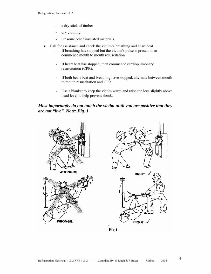
Most importantly do not touch the victim until you are positive that they are not “live”. Note: Fig. 1.
Refrigeration Electrical 1 & 2
Refrigeration Electrical 1 & 2 NRE 1 & 2 Compiled By: G Riach & R Baker Ultimo 20045
Safe working practices:
Safety precautions should always be the first priority when working on electrical equipment, as there is always the possibility of receiving an electrical shock. You should always:
Remove an electrical cord from the power outlet by grasping the plug not the cord.
Examine all electrical equipment before use.
Use danger tags when isolating permanently connected equipment.
Apply a common sense approach when working with electrical equipment.
Use good quality insulated tools when working on electrical circuits and equipment.
Avoid working in wet areas.
Wear protective clothing and steel cap boots.
Use eye, ear and breathing protection when required.
Conduct a risk assessment to evaluate any OH&S problems that may put you or others in danger.
Maintain hand and power tools to ensure compliance with the OH&S Standards.
Test electrical circuits with reliable test meters.
Refrigeration Electrical 1 & 2
Refrigeration Electrical 1 & 2 NRE 1 & 2 Compiled By: G Riach & R Baker Ultimo 20046
Review Questions: Section No: 1
1. Describe what is meant by the term duty of care:
2. What would be the sequence of steps that you would take if a work mate came in contact with a live electrical conductor?
3. What is the correct method for removing an extension cord from a power
point?
4. The current AS/NZS Wiring Rules are designed to:
5. Why is it necessary to conduct a risk assessment when working on live
electrical equipment and what safety precautions would you implement?
Refrigeration Electrical 1 & 2
Refrigeration Electrical 1 & 2 NRE 1 & 2 Compiled By: G Riach & R Baker Ultimo 20047
Module No: NRE 1&2
Section No: 2Fundamentals and derived basic units
Purpose:The aim of this section is to provide you with a complete understanding of the electrical distribution system, basic electrical units, Electron theory and electrical circuit characteristics.
To maintain our standard of living it is essential that we have an electricity supply system that has sufficient energy and is reliable to ensure consistency for consumers.
The electrical industry is large and diverse in its nature and can be divided into three main areas as follows:
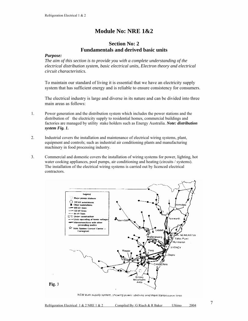
1. Power generation and the distribution system which includes the power stations and the distribution of the electricity supply to residential homes, commercial buildings and factories are managed by utility stake holders such as Energy Australia. Note: distribution system Fig. 1.
2. Industrial covers the installation and maintenance of electrical wiring systems, plant, equipment and controls; such as industrial air conditioning plants and manufacturing machinery in food processing industry.
3. Commercial and domestic covers the installation of wiring systems for power, lighting, hot water cooking appliances, pool pumps, air conditioning and heating (circuits / systems). The installation of the electrical wiring systems is carried out by licenced electrical contractors.
Refrigeration Electrical 1 & 2
Refrigeration Electrical 1 & 2 NRE 1 & 2 Compiled By: G Riach & R Baker Ultimo 20048
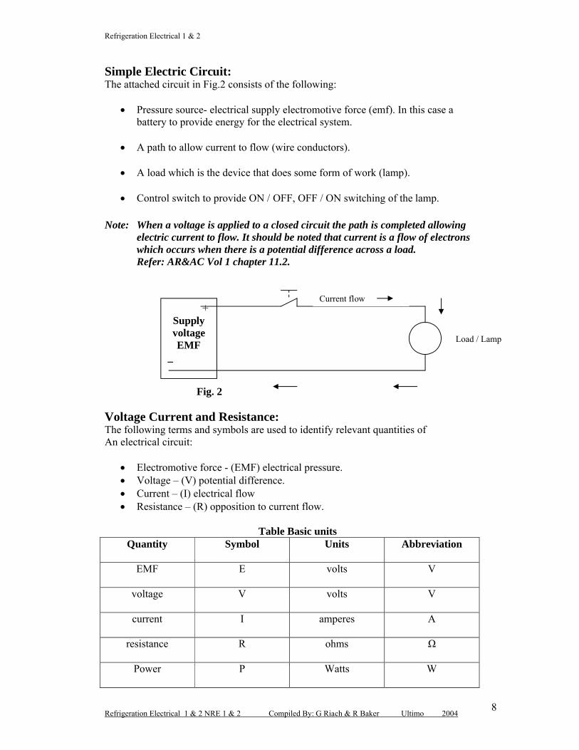
Simple Electric Circuit:The attached circuit in Fig.2 consists of the following:
Pressure source- electrical supply electromotive force (emf). In this case a battery to provide energy for the electrical system.
A path to allow current to flow (wire conductors).
A load which is the device that does some form of work (lamp).
Control switch to provide ON / OFF, OFF / ON switching of the lamp.
Note: When a voltage is applied to a closed circuit the path is completed allowing electric current to flow. It should be noted that current is a flow of electrons which occurs when there is a potential difference across a load.Refer: AR&AC Vol 1 chapter 11.2.
Voltage Current and Resistance:The following terms and symbols are used to identify relevant quantities ofAn electrical circuit:
Electromotive force - (EMF) electrical pressure. Voltage – (V) potential difference. Current – (I) electrical flow Resistance – (R) opposition to current flow.
Table Basic unitsQuantity Symbol Units Abbreviation
EMF E volts V
voltage V volts V
current I amperes A
resistance R ohms Ω
Power P Watts W
+Supply voltageEMF
_
Current flow
Load / Lamp
Fig. 2
Refrigeration Electrical 1 & 2
Refrigeration Electrical 1 & 2 NRE 1 & 2 Compiled By: G Riach & R Baker Ultimo 20049
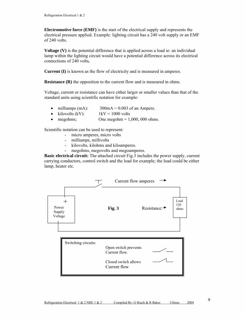
Electromotive force (EMF) is the start of the electrical supply and represents the electrical pressure applied. Example: lighting circuit has a 240 volt supply or an EMF of 240 volts.
Voltage (V) is the potential difference that is applied across a load ie: an individual lamp within the lighting circuit would have a potential difference across its electrical connections of 240 volts.
Current (I) is known as the flow of electricity and is measured in amperes.
Resistance (R) the opposition to the current flow and is measured in ohms.
Voltage, current or resistance can have either larger or smaller values than that of the standard units using scientific notation for example:
milliamps (mA): 300mA = 0.003 of an Ampere. kilovolts (kV): 1kV = 1000 volts megohms; One megohm = 1,000, 000 ohms.
Scientific notation can be used to represent:- micro amperes, micro volts- milliamps, millivolts- kilovolts, kilohms and kiloamperes.- megohms, megovolts and megoamperes.
Basic electrical circuit: The attached circuit Fig.3 includes the power supply, current carrying conductors, control switch and the load for example; the load could be eitherlamp, heater etc.
Refrigeration Electrical 1 & 2 NRE 1 & 2 Compiled By: G Riach & R Baker Ultimo 200410
The switching symbols above are classified as single pole single throw and can have either normally open (N/O) or normally closed (N/C) contacts.Electrical characteristics of materials:Electrical materials may either be conductors, insulators or semiconductors.
Conductors are materials that allow current to pass freely for example: copper, brass, silver and aluminium are good conductors and all four are used extensively throughout the refrigeration, air conditioning and electrical industries. Note: Fig 4
Fig. 4 conductor
Insulators are materials that block current flow that is they offer a very high resistance to current flow. Note: Fig 5
Fig. 5 insulator-
- - -- -- --- -
Conductor
-
Electrons pass through
Electrons (-)
Electrons do not pass through
--
-
-
-
-
-
--
-
Insulator
-
Refrigeration Electrical 1 & 2
Refrigeration Electrical 1 & 2 NRE 1 & 2 Compiled By: G Riach & R Baker Ultimo 200411
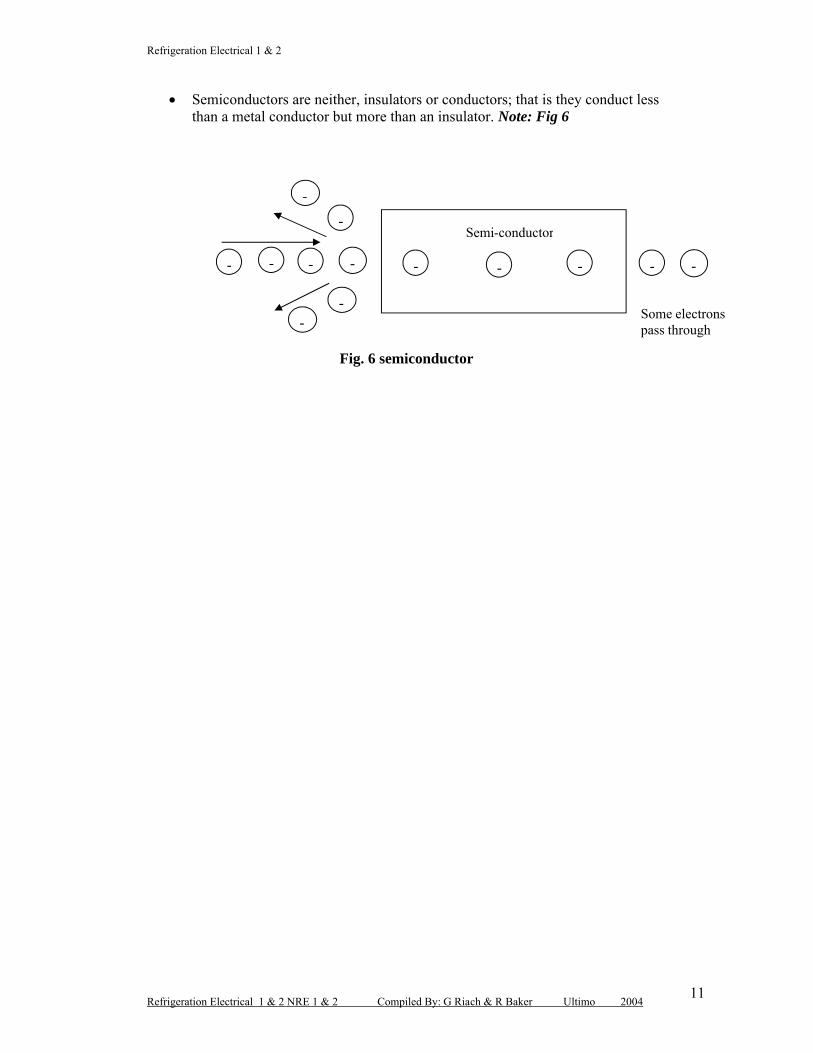
Semiconductors are neither, insulators or conductors; that is they conduct less than a metal conductor but more than an insulator. Note: Fig 6
Fig. 6 semiconductor
- ----- -
-Semi-conductor
-
-
-
-Some electronspass through
-
Refrigeration Electrical 1 & 2
Refrigeration Electrical 1 & 2 NRE 1 & 2 Compiled By: G Riach & R Baker Ultimo 200412
Review Questions: Section No: 2
1. Opposition to current is termed:(a) Flow(b) Pressure(c) Voltage(d) Resistance: ( )
2. A battery provides a source of electrical:(a) resistance(b) pressure(c) displacement(d) opposition: ( )
3. The symbol to represent potential difference is:(a) E(b) I(c) V(d) R ( )
4. Opening the main control switch in a light circuit will:(a) stop the current flow(b) reduce the circuit voltage(c) increase the circuit current(c) reduce the circuit power ( )
5. The unit of electrical current is:(a) watt(b) ohm(c) ampere(d) volt ( )
6. The basic electrical circuit consists of:
7. Describe what is meant by the term conductor:
Refrigeration Electrical 1 & 2
Refrigeration Electrical 1 & 2 NRE 1 & 2 Compiled By: G Riach & R Baker Ultimo 200413
8. Describe the main difference between an insulator and a semiconductor:
9. Define the term resistance when related to electrical circuits:
10. Name the two main types of single pole switching arrangements used to energise or de-energise an electrical circuit:
Refrigeration Electrical 1 & 2
Refrigeration Electrical 1 & 2 NRE 1 & 2 Compiled By: G Riach & R Baker Ultimo 200414
Module No: NRE 1&2
Section No: 3
OHMS LAW
Purpose:The aim of this section is to provide you with the required skills to implement Ohm’s Law to determine various values such as voltage, current, resistance and power when applied to electrical circuits.
Reference: ARAC Vol:1 pages; 11.7 : 11.14
Ohm’s law states: current flow is directly proportional to the applied voltage and inversely proportional to the resistance, provide the temperature remains constant.
Calculating current, resistance and voltage using Ohms Law:
Example No: 1.Determine the electrical supply voltage, if the resistance of an electric jug element is 100 ohms and has a current flow of 2.4 amperes.
Transposition: V = I x R V = 2.4 x 100 V = 240 volts.
Example No: 2.An electric heater element has a current flow of 12 amperes with a 240 volt supply. Calculate the heater elements resistance.
By simple transposition: R = V R = 240 R = 20 Ohms. I 12
Where:I = Current (amperes)V = Voltage (volts)R = Resistance (ohms)
I R
V
Refrigeration Electrical 1 & 2
Refrigeration Electrical 1 & 2 NRE 1 & 2 Compiled By: G Riach & R Baker Ultimo 200415
Example No: 3Determine the current flow in an electrical lamp circuit with a supply of 240 volts and a lamp resistance of 200 ohms.
Transposition: I = V I = 240 I = 1.4 amperes. R 200
Power in electrical circuit:The purpose of many electrical circuits is to convert electrical energy into other forms of energy, for example:
Heat energy (hot plate on electric stove) Magnetic energy (electrical motor) Chemical energy (battery charging).
The basic electrical circuit can be represented by the block diagram of Fig.1.
Fig.1.The term energy means: the capacity or ability to do work for example:
The capacity to light a light bulb To heat a home Electric motor to drive an evaporator fan.
The term work means: the transferring or transforming energy for example:
Electrical energy converted to heat energy Electrical energy converted to mechanical energy.
The term power means: the rate of doing work, for example: Electrical power is the rate at which work done as current flows through a
circuit. Mechanical power is the rate at which work is done as an object is moved
against opposition over a certain distance.
Note: The standard international (SI) unit of power is the watt. Symbol W.1000 watts = one kilowatt (1kW).
ElectricalSupply
Electrical energy transfer
(Circuit conductors)
Energy conversion
(Load)
Refrigeration Electrical 1 & 2
Refrigeration Electrical 1 & 2 NRE 1 & 2 Compiled By: G Riach & R Baker Ultimo 200416
Electrical equipment is rated in terms of voltage and power for example: Light bulb: 240V, 60 W Hotplate: 240V, 2400W (2.4kW) Hot water element: 240V, 4800W 4.8 (kW).
The power consumed is dependent upon the applied voltage and the circuit current and the basic electrical power relationship is as follows:
Example No: 1.Calculate the power dissipated in an electrical heater element with a supply of 240 volts and a current flow of 3 amperes:
Transposition: P = V x I P = 240 x 3 P = 720 W
Example No: 2.An electric heater element has a resistance of 24 ohms and is connected to 240 volt power supply. Determine the electrical power consumed by the heater element:
Transposition:
* current flow ? I = V I = 240 I = 10 amperes R 24
* Power ? P = V x I P = 240 x 10 P = 2400 W or 2.4 kW
Example No: 3.Determine the current flow of an electric heater element that consumes 5.2 kW and is connected to a 240 volt supply:
Transposition: I = P I = 5200 I = 2.166 amperes V 240
Where;I = Current (amperes)V = Voltage (volts)P = Power (watts, W / kW)
P
V I
Refrigeration Electrical 1 & 2
Refrigeration Electrical 1 & 2 NRE 1 & 2 Compiled By: G Riach & R Baker Ultimo 200417
2. Current in an electrical circuit is directly proportional to:(a) voltage(b) time(c) resistance (d) temperature ( )
3. A high resistance causes a:(a) short circuit (b) high current(c) low voltage(d) low current ( )
4. If the voltage applied to a circuit is halved, the circuit current will:(a) double(b) halve(c) remain constant(d) decrease to zero ( )
5. If the voltage is held constant and the circuit resistance is halved, the circuit current will:(a) double(b) remain constant (c) halve(d) decrease to zero ( )
6. From the attached details in the circuit below, determine the current flow:
R = 68 ΩV = 240 V
Refrigeration Electrical 1 & 2
Refrigeration Electrical 1 & 2 NRE 1 & 2 Compiled By: G Riach & R Baker Ultimo 200418
7. An electrical heater element draws 12 amperes from a 240 volt power supply. Determine the power consumed by the heater:
8. Calculate the resistance of an electric heater element with a current flow of 9.8 amperes and a supply voltage of 240 volts:
9. An electric lamp draws 0.417 amperes from a 240 volt supply. Calculate the resistance and power consumption of the lamp.
10. If a hot water heater element has a power consumption of 4.7kW from a 240 volt power supply. Determine the current flow of the heater element:
11. List the three methods in which electrical energy can be converted into other
forms of energy:
12. A basic electrical circuit consist of:
Refrigeration Electrical 1 & 2
Refrigeration Electrical 1 & 2 NRE 1 & 2 Compiled By: G Riach & R Baker Ultimo 200419
13. Describe in your own words what is meant by electrical power.
14. In what terms is electrical equipment rated :
15. Define in your own words Ohm’s Law:
Refrigeration Electrical 1 & 2
Refrigeration Electrical 1 & 2 NRE 1 & 2 Compiled By: G Riach & R Baker Ultimo 200420
Module No: NRE 1&2
Section No: 4
Series / Parallel CircuitsPurpose:The aim of this section is to provide you with the underpinning knowledge to evaluate electrical quantities (which include voltage, current, resistance and power) in regards to series and parallel circuits.
Series Circuits:Where a number of resistors or devices; are connected so as the total current flows through each one they are said to be connected in series. Note Fig.1 and 2.
In the series circuit below resistors R1 & R2 are connected in series note: the currents flow remains the same throughout the whole circuit.
Note: both electrical circuits below have a volt meter (V) and ampere meter connected measuring the supply voltage and current flow:
The volt meter is connected in parallel the load The ampere meter is connected in series with the load The circuit in Fig.2 has two switches in series with a load.
Fig.1
Fig. 2
+Power
Supply240 V
_
R 2 / 15
Current flow = 9.6 amperes
Current flow = 9.6 amperes -
R1 / 10A
V
+Power Supply
-
LoadA
V
Two switches connected in series with the load.
Refrigeration Electrical 1 & 2
Refrigeration Electrical 1 & 2 NRE 1 & 2 Compiled By: G Riach & R Baker Ultimo 200421
Resistance in a series circuit:
The series circuit in Fig.1 contains two resistors in series R1 has a resistance of 10 ohms and R2 has 15 ohms. To determine the total resistance for this circuit the following formula applies:
Total R = R1 + R2 Total R = 10 + 15 = 25 ohms.
Current in a series circuit: The current flow in Fig 1 can be determined by using Ohm’s Law once you have established circuit resistance and in this case it was 25 ohms.
Example: I = V Where: I = current flow in amperes R V = Supply voltage in volts
R = total circuit resistance I = 240 = 9.6 amperes. 25
Voltage:From the circuit in Fig 1 it can be proved using Ohm’s Law that the supply voltage is 240 volts.
Example: V = I x R V= 9.6 x 25 = 240 volts.
Because R1 and R 2 are in series they will share the supply voltage in other words there will be a voltage drop across each resistor: For Example:
Note: VR1 & VR2 equals the voltage drop across each resistor.
VT equals the total voltage of the circuit.
Voltage drop: VR1= I x RVR1 = 10 x 9.6 = 96 volts
Voltage drop: VR2= I x RVR2 = 15 x 9.6 = 144 volts
Total voltage VT = VR1 + VR2 VT = 96 + 144 = 240 volts
Refrigeration Electrical 1 & 2
Refrigeration Electrical 1 & 2 NRE 1 & 2 Compiled By: G Riach & R Baker Ultimo 200422
Power:The power dissipated from the resistors in the circuit in Fig 1, can be determined by the following formula:
P = V x I Where: P = power in wattsV = voltage in volts I = current in amperes.
Example 1: The total power consumed:
P = V x I
P = 240 X 9.6 = 2304 watts or 2.304 kW
The power in each resistor can also be determined:
Resistor (R1)
PR1 = VR1 x I
PR1 = 96 x 9.6 = 921.6 watts.
Resistor (R2)
PR2 = VR2 x I
PR2 = 144 x 9.6 = 1382.4 watts.
The total power can also be determined by:
PT = PR1 + PR2
PT = 921.6 + 1382 .4 = 2304 watts or 2.304 kW
Example 2:A 240 volt supply has three resistors connected in series R1 has a resistance of 5
ohms, R2 / 11 ohms and R3 / 26 ohms. Determine in the space provided the:
Total current flow Voltage drop across each resistor Power consumed by each resistor Total power consumed.
Refrigeration Electrical 1 & 2
Refrigeration Electrical 1 & 2 NRE 1 & 2 Compiled By: G Riach & R Baker Ultimo 200423
Parallel Circuits:Where a number of resistors or devices; are connected so as the total current flow is divided between each resistor they are said to be connected in parallel. Note Fig.3.
Resistance:The parallel circuit in figure 3 contains two resistors in parallel R1 has a resistance of 40 ohms and R2 has 60 ohms. To determine the total resistance for this circuit the following formula applies:
Current flow:Total current flow; Ohm’s Law can apply to the whole circuit or individual resistances.
I = V R
I = 240 = 10 amperes. 24
Current flow through each resistor:Resistor No: 1 Ohm’s Law I = V I = 240 = 6 amperes
R 40
Resistor No: 1 Ohm’s Law I = V I = 240 = 4 amperes R 60
+Power supply 240 volts_
A A
V
Fig. 3
R1/40 R2/ 60
A
Current flow
Refrigeration Electrical 1 & 2
Refrigeration Electrical 1 & 2 NRE 1 & 2 Compiled By: G Riach & R Baker Ultimo 200424
Voltage:The voltage across each resistor remains the same as the supply voltage that is they are connected in parallel.
Total V = VR1 = VR2 therefore: 240 = 240 = 240 volts.
Note: the electrical circuit Fig 3 has a volt meter (V) and three ampere meters connected at various points within the circuit.
The volt meter is connected in parallel with the load and supply voltage.
The ampere meters are connected in series to measure the total current flow and that of each individual resistor.
Series Parallel Circuit:Typical series parallel circuit Fig 1. And 2.
+Power supply 240 volts_
Fig. 1
Two switches connected in series with three lamps which are connected in parallel
Lamp 1 Lamp 2 Lamp 3
Refrigeration Electrical 1 & 2
Refrigeration Electrical 1 & 2 NRE 1 & 2 Compiled By: G Riach & R Baker Ultimo 200425
Typical refrigeration systems often have switches connected in series with a number of loads refer Fig.2. If either the thermostat or LP control open the condenser fan andcompressor motor will stop, however the evaporator fan motor will run continuously.
+Power supply 240 volts_
Fig. 2
Condenser
MM M
Evaporator Compressor
T LP
Refrigeration Electrical 1 & 2
Refrigeration Electrical 1 & 2 NRE 1 & 2 Compiled By: G Riach & R Baker Ultimo 200426
Review Questions: Section No: 4
1. In a series – parallel circuit: cycling and safety switches are connected in
SERIES or PARALLEL
2. The load in an electrical circuit is usually connected SERIES or
PARALLEL:
3. Three resistors are connected in series to a 240 volt power supply with R1/10,
R2/ 60 and R3/ 45 ohms respectively. Determine the total resistance, current
flow and individual across each resistance:
4. A parallel circuit consists of; two resistors R1/18 ohms and R2/32 ohms with
power supply of 240 volts. Determine the:
Total circuit resistance
Total circuit current
Individual current flow through each resistor
Voltage drop across each resistor.
Refrigeration Electrical 1 & 2
Refrigeration Electrical 1 & 2 NRE 1 & 2 Compiled By: G Riach & R Baker Ultimo 200427
5. In the space provided below draw a circuit diagram in accordance with the following details:
240 volt power supply
Two single pole switches connected in series with three lamps that are connected in parallel:
Indicate on the drawing the voltmeter and ampere meter connections to determine the voltage drop across each lamp and individual lamp current flow.
Refrigeration Electrical 1 & 2
Refrigeration Electrical 1 & 2 NRE 1 & 2 Compiled By: G Riach & R Baker Ultimo 200428
Module No: NRE 1&2
Section No: 5Electrical Meters
Purpose:The aim of this section is to provide you with the necessary knowledge and skills to competently use various electrical meters in regards fault finding, diagnosing, electrical circuits and components within refrigeration and air conditioning systems.Reference: ARAC Vol: 2 pages; 15. 4 : 15. 28
The Refrigeration / air conditioning technician should to be able to competently use a number of electrical meters in order to perform general electrical service, commissioning and maintenance procedures.
Types of meters: Test lamps, tests 240 or 415 volts Combi-check LED indicator, combination of voltage and continuity. Multi-meters can be used to check various voltages, resistances and continuity. Clamp-On (ampere meter) comes with a number of functions such as:
amperes, voltage, resistance and continuity readings. Watt-meter used to determine the power consumption of circuit components or
the whole circuit. Neon test pencil or test screwdriver used as a quick check for voltage
presence. Megger-meter used to check the resistance of motor windings. Electrical meters can either be of analogue or digital with digital being the
most common type.
As a trainee you should make your self familiar with the various types of meters that are used within your work place. Under a qualified mentor you should become conversant with the application, connection and interpretation of various meter scales and readings.
Electrical meter connections: Volt meters are connected in parallel with the load
Ampere meters are connected in series with the load.
Clamp-on tong tester connected with the clamp around the active cable to the load being measured
Ohm meter readings must be taken with the component being tested completely isolated and disconnected from the supply voltage.
Test lamps are used to check various voltages throughout electrical circuits and can either be connected from active to neutral and active to earth. Test lamps are not suitable for circuits that have earth leakage protection as they may trip the main circuit breaker. Voltage ranges from 240 to 415 volts.
Refrigeration Electrical 1 & 2
Refrigeration Electrical 1 & 2 NRE 1 & 2 Compiled By: G Riach & R Baker Ultimo 200429
Multi-meter combines: resistance, voltage, amperes and continuity in the oneunit.
Test pencil or screw driver is used as a quick reference for voltage checks and for a more accurate reading the voltage scale on a multimeter should be used.
Megger-meter: the megger is used when an expected leakage to earth through a motor windings and must be connected with one probe to each winding in turn and the other to frame (earth). Set on the 500 volt scale on single phase circuits or 1000 volts for three phases. A safe reading would be above 1 megohm (1 000 000 ohms).
Note: reference to ARAC Volume 1 Chapter 15 Electrical Meters.
Refrigeration Electrical 1 & 2
Refrigeration Electrical 1 & 2 NRE 1 & 2 Compiled By: G Riach & R Baker Ultimo 200430
Review Questions Section No: 5
Q.1 A volt meter is connected in series or parallel when measuring the voltage
drop across an electric motor:
Q.2 List three electrical measuring meters which can be used to determine that a
voltage is present:
Q.3 What is the purpose of a Megger – meter and what are the voltage scales
used for both single and three phase motors: :
Q.4 What precautions should be taken when measuring the resistance of an
electric motor when using an ohm-meter?
Q.5 Describe two methods for determining the power consumption of an
electrical hot water heater:
Q.6 When measuring the current flow of an electric motor the ampere meter is
connected in series or parallel:
Refrigeration Electrical 1 & 2
Refrigeration Electrical 1 & 2 NRE 1 & 2 Compiled By: G Riach & R Baker Ultimo 200431
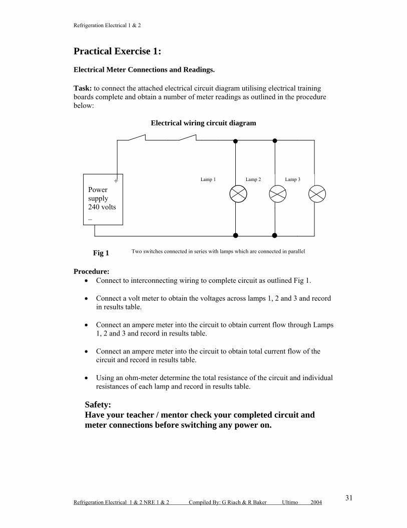
Practical Exercise 1:
Electrical Meter Connections and Readings.
Task: to connect the attached electrical circuit diagram utilising electrical training boards complete and obtain a number of meter readings as outlined in the procedure below:
Electrical wiring circuit diagram
Procedure: Connect to interconnecting wiring to complete circuit as outlined Fig 1.
Connect a volt meter to obtain the voltages across lamps 1, 2 and 3 and record in results table.
Connect an ampere meter into the circuit to obtain current flow through Lamps 1, 2 and 3 and record in results table.
Connect an ampere meter into the circuit to obtain total current flow of the circuit and record in results table.
Using an ohm-meter determine the total resistance of the circuit and individual resistances of each lamp and record in results table.
Safety:Have your teacher / mentor check your completed circuit and meter connections before switching any power on.
Fig 1 Two switches connected in series with lamps which are connected in parallel
+Power supply 240 volts_
Lamp 1 Lamp 2 Lamp 3
Refrigeration Electrical 1 & 2
Refrigeration Electrical 1 & 2 NRE 1 & 2 Compiled By: G Riach & R Baker Ultimo 200432
Recorded Results:Components Voltage Current Resistance
Total Circuit
Lamp 1
Lamp 2
Lamp 3
Conclusion: From the results that you have obtained determine the power consumed of each lamp and the total circuits, power consumption. Using Ohm’s Law indicate your results in the space provided below: (note show all working).
Refrigeration Electrical 1 & 2
Refrigeration Electrical 1 & 2 NRE 1 & 2 Compiled By: G Riach & R Baker Ultimo 200433
Practical Exercise 2:
Task: to connect the attached electrical circuit diagram utilising electrical training boards and obtain a number of meter readings as outlined in the procedure below:
Procedure: Connect the interconnecting wiring to complete circuit as outlined Fig 2.
Make sure your teacher / mentor has checked your circuit before the power is switched on. Turn power on under supervision.
Using a set of test lamps test to see if a voltage exists across the motor supply terminals and record.
Using a clamp- on tong tester measure the current flow of the motor and record.
With the power isolated from the motor using a megger-meter check the resistance of the motor winding against the established earth leakage and record.
Recorded motor results
VoltageTest lampsCurrent FlowClamp – On MeterEarth LeakageMegger Meter.
+Power supply 240 volts
_
M
Shaded Pole Motor
Fig. 2
Refrigeration Electrical 1 & 2
Refrigeration Electrical 1 & 2 NRE 1 & 2 Compiled By: G Riach & R Baker Ultimo 200434
Practical Exercise 3:
Watt Meter Connection:Task: to connect the attached electrical circuit diagram utilising electrical training boards and using a watt meter obtain the total power consumed by the circuit.Note: watt meter connections below:
Watt meter reading:
Using a voltmeter and an ampere-meter and the above circuit Fig.3 connect the meters, record and determine the total power consumed using Ohm’s Law to validate your conclusion in the space provided below:
+Power supply 240 volts
_
M
Shaded Pole Motor
Fig. 3
L
V2
The wattmeter consists of two internal windings or coils: Current coil extremely low resistance to current flow.
M and L are connected in series with the load.
Potential coil or voltage coil, very high resistance to current flow with V1 and V2 connected in parallel to the load.
Through a process of internal calculation of voltage times the current the meter indicates a result in watts.
The same result can be obtained with a volt and ampere meter using Ohm’s Law from your recorded results: P = V x I.
WM
V1
Refrigeration Electrical 1 & 2
Refrigeration Electrical 1 & 2 NRE 1 & 2 Compiled By: G Riach & R Baker Ultimo 200435
Module No: NRE 1&2
Section No: 6
Capacitors
Purpose:The aim of this section is to provide you with knowledge and skills that apply to capacitance and how capacitors are utilized in refrigeration and air conditioning electrical circuits to improve the starting and running characteristics of variousmotors. Reference ARAC Vol: 1. 12.13 & 14.5
A capacitor is a device used for storing an electrical charge.
A battery also stores positive charges on one plate and negative charges on another plate. A capacitor works on the same principle the difference being that a capacitor has larger plate areas and therefore can hold a larger charge.
A capacitor has to be connected to a power supply to be charge.
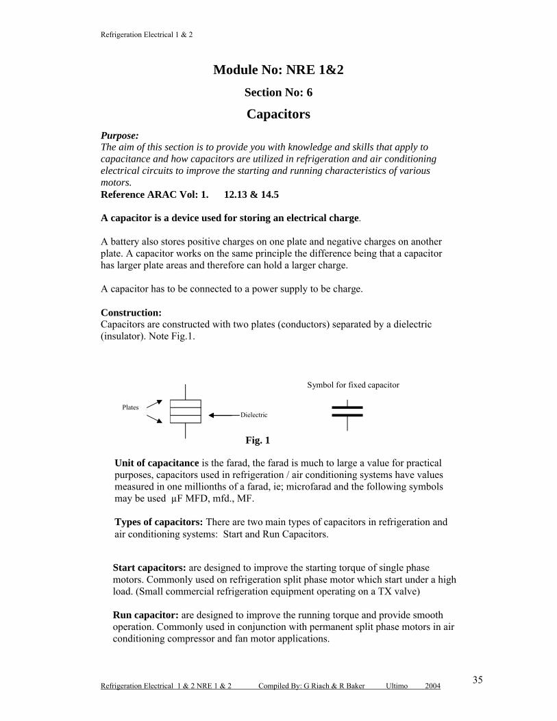
Construction:Capacitors are constructed with two plates (conductors) separated by a dielectric (insulator). Note Fig.1.
Start capacitors: are designed to improve the starting torque of single phasemotors. Commonly used on refrigeration split phase motor which start under a high load. (Small commercial refrigeration equipment operating on a TX valve)
Run capacitor: are designed to improve the running torque and provide smooth operation. Commonly used in conjunction with permanent split phase motors in air conditioning compressor and fan motor applications.
Plates Dielectric
Unit of capacitance is the farad, the farad is much to large a value for practical purposes, capacitors used in refrigeration / air conditioning systems have values measured in one millionths of a farad, ie; microfarad and the following symbols may be used µF MFD, mfd., MF.
Types of capacitors: There are two main types of capacitors in refrigeration and air conditioning systems: Start and Run Capacitors.
Symbol for fixed capacitor
Fig. 1
Refrigeration Electrical 1 & 2
Refrigeration Electrical 1 & 2 NRE 1 & 2 Compiled By: G Riach & R Baker Ultimo 200436
Fig. 2
Ratings of typical capacitors used in refrigeration and air conditioning systems can vary as follows:
Start Capacitor: 50µF to 200µF Run Capacitor: 2µF to 40µF
Charging and discharging capacitors:
If a capacitor is discharged, then the capacitor has an equal number of electrons on each plate.
When a voltage is applied across the capacitor plates, electrons flow from one plate to the other plate. The capacitor is fully charge when all the positive electrons form on one of the plates.
The capacitor discharges when there is a current flow between the two plates (usually through a motor).
The capacitor is completely discharged once there are an equal number of electrons back on each plate. Note: Fig. 3.
Most capacitors are fitted with a bleed resistor to allow the capacitor to discharge when not in use.
Capacitors are used in the refrigeration / Air conditioning industry for singlephase motor starting and running (a.c.), to improve starting torque and running torque.
It should also be noted that the current will lead the voltage in an alternating circuit.
M
A N
T LP HP
OL
Permanent Split compressor motor circuit fitted with a Run Capacitor.
The run capacitor in this circuit continually charges and discharges across the two winding of the motor compressor. Main (M), Auxiliary (A) and (C) Common.
M
A
C
Refrigeration Electrical 1 & 2
Refrigeration Electrical 1 & 2 NRE 1 & 2 Compiled By: G Riach & R Baker Ultimo 200437
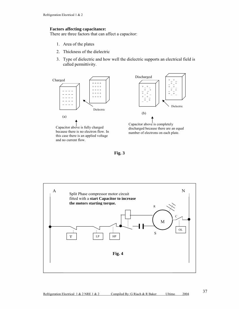
Factors affecting capacitance:There are three factors that can affect a capacitor:
1. Area of the plates
2. Thickness of the dielectric
3. Type of dielectric and how well the dielectric supports an electrical field is called permittivity.
Fig. 3
M
A N
T LP HP
OL
Split Phase compressor motor circuit fitted with a start Capacitor to increase the motors starting torque.
Fig. 4
R
S
C
_ _ _ __ _ _ __ _ _ __ _ _ __ _ _ _
+ + + ++ + + ++ + + + + + + ++ + + +
Capacitor above is fully charged because there is no electron flow. In this case there is an applied voltage and no current flow.
+ _ + __ + _ ++ _ + _+ _ + __ + _ +
+ _ + __ + _ ++ _ + __ + _ ++ _ + _
Capacitor above is completely discharged because there are an equal number of electrons on each plate.
ChargedDischarged
(a)(b)
Dielectric Dielectric
Refrigeration Electrical 1 & 2
Refrigeration Electrical 1 & 2 NRE 1 & 2 Compiled By: G Riach & R Baker Ultimo 200438
Capacitors in series:
In the event that you are required to replace a faulty capacitor in a hurry and you don’t have the exact replacement in your van, you may have a number of various capacitors and when put in a combination using the following calculation you may be able to complete the job.
Note: when connecting capacitors in series the total capacitance is always lower than the lowest individual capacitance.
Refrigeration Electrical 1 & 2 NRE 1 & 2 Compiled By: G Riach & R Baker Ultimo 200439
Capacitors in parallel:
When connecting capacitors in parallel the total capacitance is equal to the sum of all the individual capacitances.
C1 = 10µF C2 = 15µF C3 = 25µF
Formula: CT = C1 + C2 + C3
Calculate the total capacitance: CT = C1 + C2 + C3CT = 10 + 15 + 25CT = 50 microfarads
+
__
Refrigeration Electrical 1 & 2
Refrigeration Electrical 1 & 2 NRE 1 & 2 Compiled By: G Riach & R Baker Ultimo 200440
Review Questions Section: No 6
Q.1 Describe the main purpose of the capacitor:
Q.2 List three factors which will influence the capacitance of a capacitor:
Q.3 What is the main purpose for using either start or run capacitors in
refrigeration or air conditioning systems?
Q.4 What is the main purpose for the bleed resistor on a capacitor?
Q.5 Describe how a capacitor charges and discharges:
Q.6 How are capacitors rated within the refrigeration / air conditioning industry and
what are the three main symbols for capacitance?
Refrigeration Electrical 1 & 2
Refrigeration Electrical 1 & 2 NRE 1 & 2 Compiled By: G Riach & R Baker Ultimo 200441
Q. 7 When servicing a refrigeration system a faulty capacitor has be identified
unfortunately you do not have the exact size, however you have a number of
various sizes in the van. How would overcome this situation in order to retain
the customer satisfaction?
Q.8 Name the two main types of capacitors used on refrigeration and air
conditioning systems:
Q.9 Three capacitors are connected in series with individual capacitances of 35µF,
50µF and 65µF for each capacitor. Determine the total capacitance of the
circuit:
Q.10 Calculate the total capacitance of a parallel circuit with individual capacitors
having a capacitance of 25µF, 110µF and 75µF.
Refrigeration Electrical 1 & 2
Refrigeration Electrical 1 & 2 NRE 1 & 2 Compiled By: G Riach & R Baker Ultimo 200442
Module No: NRE 1&2
Section No: 7
Magnetism and Electromagnetism
Purpose:The aim of this section is to introduce you to the different ways in which magnetism is developed such as permanent magnets, electromagnets, electromagnetic inductionand applications of each method. In addition various types: of transformers; their principle operation, ratios, voltages, currents and applications.Reference: ARAC Vol: 1 pages; 11.19 : 11.21
Magnetism: Magnetism consists of lines of force as shown in Fig. 1 which indicates the magnetic field (Flux) of a bar magnet where the lines of force are endless moving from the north to the south poles.
Fig. 1
It should be noted that when two poles are place near each other, they will react as follows:
Unlike poles attract Like poles repel.
Magnetic and Non – Magnetic Materials:
Some materials are influenced by a magnetic field which are said to have a high permeability ie; low resistance to the lines of force / flux and are referred to as magnetic materials, which include:
Iron Iron alloy Ferrite.
Non magnetic materials are not affected by a magnetic field for example: Air Water Copper, brass or aluminium Plastic Paper.
N S
Lines of force
Refrigeration Electrical 1 & 2
Refrigeration Electrical 1 & 2 NRE 1 & 2 Compiled By: G Riach & R Baker Ultimo 200443
Applications for permanent magnets: Loud speakers Compass for direction Door gaskets on refrigerators.
Electromagnets:If a conductor is wound around a length of plastic conduit forming a coil and energised by an EMF (electromotive force) a current will flow through the coil and by moving an iron core through the coil of wire, lines of force will be induced into theiron and thus a magnet is produced (electromagnet). This is the basic principle of magnetic induction.
The strength of a magnetic field by an electromagnet is governed by: Number of turns within the coil Current flow through the coil Type of core.
Saturation:As the current in the coil increases, the flux within the coil increases as well. Within a certain point the ability of the core to absorb any more magnetic flux becomes limited. At this point it is referred to as saturation in which any further increase in current will not cause a corresponding increase in magnetic flux.
Fig. 2 Magnetic saturation
Applications:
Electromagnetism is the basis of operation electrical components within the electrical refrigeration and air conditioning industries for example:
Single and three phase motors Generators / alternators Transformers Solenoid coils Relay coils / contactors etc.
Saturation
Current in coil
Flux
Refrigeration Electrical 1 & 2
Refrigeration Electrical 1 & 2 NRE 1 & 2 Compiled By: G Riach & R Baker Ultimo 200444
Transformers:A transformer is a device which transforms voltage from one level to another (240 V step down to 24 V) through electromagnetic induction.
The construction of a transformer is made up of two separate coils which are electrically isolated from a laminated coil coupled as follows:
Windings:A transformer has two windings the highest voltage has a large number of fine gauge turns while the winding with the lowest voltage has a low number of large gauge turns.
Core:The core is made up of a number of thin silicon sheet steel laminations in order toreduce eddy current losses and allow the free flow of magnetic flux
Principle operation:When the primary winding is connected to an AC supply, an alternating flux is produced in the laminated core and this flux links up with the turns on the primary and secondary windings and thus inducing an EMF into both windings.Thus transfer of energy from the primary to the secondary takes place.
Primary voltage and coil
Secondary voltage and coil
Laminated iron core
240 volts24 volts
Fig. 3.
Refrigeration Electrical 1 & 2
Refrigeration Electrical 1 & 2 NRE 1 & 2 Compiled By: G Riach & R Baker Ultimo 200445
Types of Transformer:There are two main types of transformers: step down and step up.
Example: Step down: primary winding 240 volts and secondary 24 volts. Step up primary 24 volts and the secondary 240 volts.
Transformer ratings:Transformers are rated in Volt-Amps (VA) (volts x amps) or kVA
Example: a step down transformer has a 24 VA rating: that is the secondary (volts x amps) 24 x 1 = 24 VA.
Transformer ratios:When there is a constant core flux and frequency in the core of an ideal transformer, the relationship between the number of turns, voltage and current ratios can be determined by the following calculations:
Example:1. An ideal step down transformer has 1600 primary turns, a primary voltage of
250 volts a.c. and a primary current of 1 amp. If the secondary winding has 200 turns, determine the:
Secondary voltage Secondary current.
By using the ratio method the secondary voltage and current can be determined as follows:
Transformer applications: Step down 240 to 24 volts control circuits Soldering irons (step down form 240 to 12 volts) Motor fan speed control (single phase motors) Autotransformer (three phase reduced voltage starting).
Refrigeration Electrical 1 & 2
Refrigeration Electrical 1 & 2 NRE 1 & 2 Compiled By: G Riach & R Baker Ultimo 200446
Review Questions Section: No 7
1.. The unit of inductance is the:(a) henry(b) ohm(c) farad(d) Watt.
2. A conductor wound in the form of a spiral is called a:(a) coil (b) ermanent magnet(c) capacitor(d) Generator.
3. Laminations are used in the core of a transformer to:(a) reduce its physical size(b) decrease eddy current loss(c) increase the effective core area(d) Reduce current flow.
4. The secondary voltage of a transformers is produced by:(a) mutual induction(b) self induction(c) electrostatic induction(d) Current conduction.
5. Silicon steel is used in a transformer core due to its:(a) high resistance(b) low weight(c) high permeability(d) Low noise factor.
6. List four non-magnetic materials:
7. The two main types of transformers are:
Refrigeration Electrical 1 & 2
Refrigeration Electrical 1 & 2 NRE 1 & 2 Compiled By: G Riach & R Baker Ultimo 200447
8. List the three main components of a transformer:
9. List four applications where electromagnetism is utilised within the
refrigeration / air conditioning industry:
10 Describe in your own words what is meant by saturation in reference to
electromagnetism:
11. A transformer has a secondary voltage of 32 volts when connected to a 240
volt 50 HZ supply. If the primary winding has 1600 turns determine the
number of turns in the secondary:
12. Determine the primary current of a transformer which has a secondary current
of 8 amperes, primary voltage 240 and secondary voltage of 24 volts:
Refrigeration Electrical 1 & 2
Refrigeration Electrical 1 & 2 NRE 1 & 2 Compiled By: G Riach & R Baker Ultimo 200448
Module No: NRE 1&2
Section No: 8
Alternating Current (AC)
Purpose: The aim of this section is to introduce you to the basic principles of “alternating current” which includes the sine wave, frequency, Vmax voltage, peak to peak voltage, RMS voltage, power and three phase power generation.Reference: ARAC Vol 1, pages 11.3 : 11.5.
What is alternating current (a.c.)? In a Direct Current (d.c.) circuits, the flow of electrons is only in one direction. However in an Alternating Current circuit, the flow of electrons is in one direction for one half cycle and then in the opposite direction for the next half cycle.
Production of electricity: (ARAC Vol 1, page 11.28 – 11.30)Electricity can be produced either by a generator or an alternator. The major difference between the two is the output, a generator produces a direct current output and an alternator produces an alternating output. A sinewave demonstrates a typical A.C. output that is when a conductor moves in a circular path through a magnetic field. Refer to Fig. 1.
1 Cycle
Fig. 1
Note: The sinusoidal waveform travels 360 electrical degrees for each cycle.
T0
340 V
+
–
340 V
0.02 sec
360○
180○
90○
270○
RMS = 0.707
Refrigeration Electrical 1 & 2
Refrigeration Electrical 1 & 2 NRE 1 & 2 Compiled By: G Riach & R Baker Ultimo 200449
Terms used in relation to an (A.C. waveform):
An A.C. waveform has a number of important characteristics and they include:
V max values: (from zero to the peak of each half cycle).
Peak to peak values: (is the sum of the two half cycles).
Complete cycle: (one complete revolution of the sine wave 360 degrees).
Period Time (T): (time taken to complete one cycle).
Frequency: (number of cycles per second measured in HZ).
Note: Refer to Fig. 2.
Fig. 2
Example:From the attached waveform determine:
(a) Peak to peak value
(b) V Maximum value
(c) Periodic time
(d) Frequency. ( f = 1/T
(a) Vp – p = +340 volts + - 340 volts
Vp _ p = 780 volts
(b) V max = 340 volts
+
T
340 V
–
340 V
1 cycle
Vmax
Vp _ p
20 ms
0
Refrigeration Electrical 1 & 2
Refrigeration Electrical 1 & 2 NRE 1 & 2 Compiled By: G Riach & R Baker Ultimo 200450
(c) Periodic Time = 20 milliseconds
(d) Frequency = 1T (HZ)
Convert milliseconds to seconds (20 ms = 0.02 sec)
f = 1 = 50 cycles / second or 50 HZ 0.02
Root-mean square (RMS) value:Peak to peak values of the waveform are used in the electronics industry where as in the refrigeration / air conditioning industries the RMS value is used. The RMS value of an alternating voltage or current is 0.707 of the Vmax value.
Example:A sinusoidal voltage has a maximum value of 340 volts. Determine the RMS value of the waveform.
V = Vmax X 0.707
V = 340 volts X 0.707
V = 240 volts.
Voltage and current in an A.C. circuit;
In an A.C. circuit the voltage can be either in phase with the current or out of phase for example:
In a purely resistive circuit the voltage and current are said to be in phase with each other. Fig. 3.
In a purely capacitive circuit the current leads the voltage by 90 electrical degrees (out of phase) Fig. 4.
In a purely inductive circuit the voltage leads the current by 90 electrical degrees (out of phase). Fig.5
Impedance (Z): is name given to the total opposition to current flow in an A.C. circuit and is expressed in ohms.
Resistive circuits: in a purely resistive A.C. circuit the voltage and current are said to be in phase and the resistance is equal to the impedance.
Note: the impedance (Z) of an A.C. circuit is equal to the overall resistance of the circuit
Refrigeration Electrical 1 & 2
Refrigeration Electrical 1 & 2 NRE 1 & 2 Compiled By: G Riach & R Baker Ultimo 200451
Fig.3
Capacitive circuit: In a purely capacitive A.C. circuit the capacitive reactance (Xc) is equal to the impedance of the circuit. Both the voltage and current are out of phase by 90 °.
Fig. 4
Inductive circuit: In purely inductive A.C. circuit inductive reactance (XL) is equal to the impedance. Both the voltage and current are out of phase by 90°
t0
+
–One Cycle
Current and voltage are “in phase”
V
I
t0
V
+
–
I
One Cycle
Current leading voltage by 90°
Refrigeration Electrical 1 & 2
Refrigeration Electrical 1 & 2 NRE 1 & 2 Compiled By: G Riach & R Baker Ultimo 200452
1
Fig. 5
Power in a single phase A.C. circuit:There are two main types of power in single phase alternating circuits:
1. Apparent power (S): only takes the voltage and current into account and is expressed in volt amperes.
S = V x I Where: S = apparent power (volt amperes VA)V = voltage (volts)I = current (amperes).
2. True power (P): takes into account how far out of phase the voltage and current are in a circuit that has both resistance and reactance.
P = V x I x pf Where:P = power (watts)V = voltage (volts)I = current (amperes)Pf = power factor ( figure between 0:1).
t0
V
+
–
I
One Cycle
Current lagging voltage by 90º
The power factor is taken where the voltage and current dissect each other .Taken somewhere between 0 and 1
In this case PF = 0.5 approx.
Refrigeration Electrical 1 & 2
Refrigeration Electrical 1 & 2 NRE 1 & 2 Compiled By: G Riach & R Baker Ultimo 200453
Example: A single phase motor is connected to a 240 volt 50HZ power supply and draws 3 amperes with a power factor of 0.87
Determine: apparent power and the true power.
Apparent power: S = V X IS = 240 x 3S = 720 volt amperes (VA)
True power: P = V x I x pfP = 240 x 3 x 0.87P = 626.4 watts.
Power factor can be expressed as the:
PF = True powerApparent power
In this case:
PF = 626.4720
PF = 0.87
Three Phase alternating Current:
Generation: The drawing below Fig.6 indicates one revolution of a simplified three phase alternator and the resulting waveform
Fig. 6
Refrigeration Electrical 1 & 2
Refrigeration Electrical 1 & 2 NRE 1 & 2 Compiled By: G Riach & R Baker Ultimo 200454
Three Phase Systems: A three phase system has three voltages, each out of phase with the other two. An ideal spread of voltages is when the three phases are travelling uniformly through the cycle. This is achieved by starting each of the phases by one third of a cycle apart, or 360/3 = 120 electrical degrees apart.
Voltages in a three phase system:The voltage produced for a three phase circuit can offer a mixture of three phase and single phase as indicated in Fig. 7 below:
ThreePhaseMotor
L1 L2 L3
SinglePhaseMotor
Fig. 7 Three phase / single phase motor circuit.
N
K1. 1
K1.2
K1.3
K1.4
K1.4
O/L
Voltages from Fig.7 L1 – L2 = 415 volts L2 – L 3 = 415 volts L1 – L3 = 415 volts From any line voltage (L1, L2, & L3) to
neutral = 240 volts From any line voltage (L1, L2, & L3) to
earth = 240 volts From neutral to earth = zero volts.
Refrigeration Electrical 1 & 2
Refrigeration Electrical 1 & 2 NRE 1 & 2 Compiled By: G Riach & R Baker Ultimo 200455
Practical Exercise:Three Phase circuit voltage testing: Under guidance of your teacher or workplace mentor using a suitable voltage testing instrument (multi-meter) validate and record the various voltages within a three phase refrigeration and or air conditioning system in accordance with the following details:
Turn the systems main isolating switch and record result in table 1. Checked to validate neutral connection and record results in table 1. Check to see if the circuit has an earth connection and record results in table. With the systems main isolation switch turned on, check to see if a voltage is
present at the systems power and control circuit boards and record in table 1.
Table No: 1 YES /NO VOLTAGE READINGMain switch on, power present?Neutral connection?
Earth connection?
System power?
Control circuit?
Refrigeration Electrical 1 & 2
Refrigeration Electrical 1 & 2 NRE 1 & 2 Compiled By: G Riach & R Baker Ultimo 200456
Review Questions Section: No 8
1. From the attached waveform calculate the following:
(a) peak to peak voltage(b) V max voltage(c) frequency (d) RMS voltage
2. Calculate the apparent and true power for a single phase motor which is connected to a 240 volt 50 HZ power supply with a power factor of 0.75.and a current flow of 5.5 amperes.
3. Describe what is meant by impedance:
4. What is the phase relationship for the voltage and current in a purely resistive
A.C. circuit:
20 ms
t0
340 V
+
–
340 V
Refrigeration Electrical 1 & 2
Refrigeration Electrical 1 & 2 NRE 1 & 2 Compiled By: G Riach & R Baker Ultimo 200457
5. What are the main differences between a purely inductive and purely
capacitive A.C. circuit?
7. Three phase systems vary from single phase, explain the main difference
between the two:
8. A three phase system consists of three phases, how many electrical degrees are
this phases apart?
9. From the details below fill in the appropriate voltages:
Three phase system: (a) Across any line voltages:
(b) From any line voltage to neutral:
(c) From any line voltage to earth:
(d) From neutral to earth:
Refrigeration Electrical 1 & 2
Refrigeration Electrical 1 & 2 NRE 1 & 2 Compiled By: G Riach & R Baker Ultimo 200458
Answers to review questions:
Section No: 1
Q. 1 Duty of care means to implement procedures and take responsibility in preventing any OH&S issues that may place you, work mates or the general public at risk of injury.
Q.2 Quickly isolate the power source.
If the circuit cannot be isolated as quick as possible remove the victim with some form of insulating material ie: dry stick a length of pope.
Call for assistance and check victims pulse.
If breathing has stopped apply mouth to mouth resuscitation.
If the heart has stopped, alternate between mouth to mouth and CPR resuscitation.
Use a blanket to keep the victim warm.
Q.3 The correct method is by grasping the plug and not the cord.
Q.4 To protect persons, livestock, and property from electric shock or physical damage that may arise from an electrical installation.
Q.5 A risk assessment should be carried out to prevent the risk of any persons obtaining an electric shock of physical injury.
Examine all electrical equipment before use. Use only good quality insulated tools. Avoid working in wet areas. Test electrical circuits with reliable test meters.
Refrigeration Electrical 1 & 2
Refrigeration Electrical 1 & 2 NRE 1 & 2 Compiled By: G Riach & R Baker Ultimo 200459
Section No: 2
Q. 1 (d)
Q. 2 (b)
Q. 3 (c)
Q. 4 (a)
Q. 5 (c)
Q.6 Pressure source (power supply),
A path to allow current to flow (wire conductors).
A load for example: a lamp.
Q.7 A conductor is a material that allows current to flow freely for example copper is a good conductor.
Q. 8 An insulator blocks current flow where as a semiconductor blocks part of the current flow.
Q. 9 Resistance is the opposition to current flow in an electric circuit.
Q.10 Normally opened (NO) Normally closed (NC).
Section No: 3
Q.1 (c)Q.2 (a)Q.3 (d)Q.4 (b)Q.5 (a)
Q.6 I = V I = 240 = 3.53 Amperes or 353 milli - amperes R 68
Q.7 P = V x I P = 240 x 12 = 2880 watts or 2.88 kW.
Q.8 R = V R = 240 = 24.48 Ohms. I 9.8
Q.9 R = V R = 240 R = 575.5 Ohms I 0.417
P = V x I P = 240 x 0.417 P = 100 watts.
Refrigeration Electrical 1 & 2
Refrigeration Electrical 1 & 2 NRE 1 & 2 Compiled By: G Riach & R Baker Ultimo 200460
Q.10 I = P I = 4700 I = 19.58 Amperes V 240
Q. 11 Heat energy, Magnetic energy and Chemical energy.
Q.12 Power source, conductors and the load.
Q.13 Electrical power is the rate in which work is done when a current flows in an electrical circuit and is measured in watts (W) or kilo watts.(kW).
Q.14 Electrical equipment is rated in terms of voltage and power.
Q.15 Current flow is directly proportional to the applied voltage and inversely proportional to the resistance provide the temperature remains constant.
Section No: 4
Q.1 Series
Q.2 Parallel
Q.3 Total R = R1 + R2 + R3 = 10 + 60 + 45 = 115 Ohms.
Total current I = V I = 240 = 2.08 Amperes. R 115
Voltage drop: V = I x R V1 = 2.08 x 10 = 20.7 VoltsV2 = 2.08 x 60 = 124.8 VoltsV3 = 2.08 x 45 = 93.6 Volts
Q.4 Total R = 1 = 1 RT = 11.52 Ohms.
1 + 1 1 + 1R1 R2 18 32
Total circuit current = I = V I = 240 I = 20.83 Amperes
R 11.52
Current flow through each resistor R1 = I = V I = 240 I = 13,33 Amperes.
R 18
R2 = I = V I = 240 I = 7.5 Amperes. R 32
Refrigeration Electrical 1 & 2
Refrigeration Electrical 1 & 2 NRE 1 & 2 Compiled By: G Riach & R Baker Ultimo 200461
Section No: 5
Q.1 Parallel
Q.2 Test lamps, multi-meter, comdi-check, (volt meter stand alone), neon test pencil.
Q.3 Megger – meter is used when a motor winding has an expected earth leakage.500 volts for single phase and 1000 volts for three phase.
Q.4 The electrical terminals of the motor must be disconnected from the supply before testing begins.
Q.5 Watt meter method direct reading. Using a volt meter and clamp on ampere meter by using Ohms Law P = V x I.
Q.6 Series.
As a student you will need to demonstrate competence in the use of various types of electrical meters used within your workplace and be able to complete Practical exercises 1, 2 & 3 within Section No:5.
A A A V
240 volts
+
_
Q. 5
Refrigeration Electrical 1 & 2
Refrigeration Electrical 1 & 2 NRE 1 & 2 Compiled By: G Riach & R Baker Ultimo 200462
Section No: 6
Q.1 A capacitor is a device used for storing an electrical charge.
Q.2 Area of the plates.Thickness of the dielectricDielectric permittivity.
Q.3 Improves the starting and running torque.
Q.4 Allows the capacitor to discharge when not in use.
Q.5 When a voltage is applied across the plates, electrons flow from one plate to the other (capacitor charged)
The capacitor is discharged when the number of electrons on each plate, are equal.
Q.6 Capacitors are rated in Mico farads. Symbols: MF, mfd, MFD.
Q.7 Use the capacitance calculations for series or parallel circuit connections to determine the correct capacitor size.
Q.8 Primary coil, secondary coil and laminated iron core.
Q.9 Relay coils, solenoid coils, electric motors, transformers, alternators.
Q.10 As the current in a coil increases and at, a certain point the ability of a coil to absorb any more flux decreases and at this point it becomes saturated.