Rapport SGC 159 • ISSN 1102-7371 • ISRN SGC-R--159-SE
SGC:s FÖRORD FUD-projekt inom Svenskt Gastekniskt Center AB avrapporteras normalt i rapporter som är fritt tillgängliga för envar intresserad. SGC svarar för utgivningen av rapporterna medan uppdragstagarna för respektive projekt eller rapportförfattarna svarar för rapporternas innehåll. Den som utnyttjar eventuella beskrivningar, resultat e dyl i rapporterna gör detta helt på eget ansvar. Delar av rapport får återges med angivande av källan. En förteckning över hittills utgivna SGC-rapporter finns på SGC´s hemsida www.sgc.se. Svenskt Gastekniskt Center AB (SGC) är ett samarbetsorgan för företag verksamma inom energigasområdet. Dess främsta uppgift är att samordna och effektivisera intressenternas insatser inom områdena forskning, utveckling och demonstration (FUD). SGC har följande delägare: Svenska Gasföreningen, E.ON Gas Sverige AB, E.ON Sverige AB, Lunds Energi AB, Göteborg Energi AB, och Öresundskraft AB. Följande parter har gjort det möjligt att genomföra detta utvecklingsprojekt: Statens Energimyndighet Catator AB E.ON Gas Sverige AB SVENSKT GASTEKNISKT CENTER AB Jörgen Held
SUMMARY A pre study concerning refuelling stations for reformate gas/hydrogen has been performed on the request of Swedish Gas Centre (SGC). The plan is to build a small-scale fuel processor for said application during 2006 as a continuation of the R&D programme in the fuel processing area. Catator has designed and evaluated small-scale fuel processors in a series of SGC-projects. The fuel processor system was abbreviated “Stur-unit” and contained reactors for steam reforming, water-gas shift and preferential oxidation, tied together in a single train unit. The STUR-unit is operated at atmospheric conditions and will produce reformate gas of fuel cell quality (normally less than 20 ppm of CO). Catator has designed and delivered a number of Stur-units ranging from 1 nm3 to 50 nm3/hr of hydrogen. Different fuels have been evaluated, both gases and liquids. Catator has also designed a pressurised system together with Intelligent Energy (abbreviated “Hestia-unit”). This unit operates at 5 – 10 bar(a) and utilizes physical purification by means of fast-cycle PSA to provide essential pure hydrogen. Both units have been subjected to successful long-term testing. The hydrogen demand in Malmoe (the proposed location for the refuelling station) is presently low and irregular since only two buses utilize Hythane (a mixture between natural gas and hydrogen) at the moment. The interest for hydrogen and hydrogen containing fuels is, however, expected to increase in a near future. E.ON Gas (the owner of the existing refuelling station) has forwarded a number of specifications for the fuel processor system. The unit shall operate on natural gas and biogas. Bio-derived liquid fuels (bio ethanol and E85 - a mixture between ethanol and gasoline) could also be interesting alternatives. Depending on the low demand for hydrogen (average of about 1 nm3/hr), the production capacity can be rather low _ 5 - 10 nm3/hr is probably more than enough for the time being. At the moment, hydrogen is produced from electricity via electrolysis (Stuart engineering). The hydrogen is stored in a number of gas cylinders and hydrogen production is performed in campaigns. The atmospheric fuel-processor system will produce reformate gas, which can be injected into natural gas to produce Hythane. One disadvantage is that the Hythane will be diluted with minor amounts of carbon oxides and nitrogen. Also, the reformate gas will be supplied at a low pressure and more power must be invested to compress the gas to the storage pressure. Another problem is that this system cannot provide pure hydrogen for an emerging fuel- cell market. The pressurized system will yield pure hydrogen at an elevated pressure. This system can easily be equipped with a fuel cell (PEM) for the internal power supply. The STUR- and Hestia-units are rather equal in size and weight (220/300 kg and 500/800 litres respectively). The operability and maintenance issues are considered equal for the units. Both units can operate on gaseous and liquid fuels and the catalyst compositions are chosen to tolerate 5 - 10 ppm (v/v) of sulphur containing compounds. The unit shall be able to operate in temperatures ranging from –40 to 40°C. The unit (including safety system) shall operate
autonomously and the alarm signals shall be arranged to enable an easy failure diagnosis for the operator. Based on the evaluation and review performed in this pre study, both technical solutions (Stur and Hestia) would work in the application. There are benefits and drawbacks with both solutions. The Stur design is simpler and somewhat cheaper (no pressure vessels). The drawback is that only reformate gas can be produced and only at atmospheric pressure. The Hestia-unit, although somewhat more expensive, will produce pure hydrogen at an elevated pressure. Start-up is somewhat quicker for the atmospheric system as compared to the pressurised system. The Hestia unit will be easier to implement into the exiting hydrogen system comprising of electrolyzer, compressors and storage cylinders. Both units will be certified according to European directives. The delivery time is approximately 10 months for both units. The price level (including commissioning & evaluations) for the atmospheric unit is about 3,700,000 SEK whereas the pressurized unit will cost about 4,800,000 SEK. The pressurised system can be equipped with a fuel cell system for the internal power supply (≈0.5 kWe) at an extra cost. A detailed offer will be supplied on request.
LIST OF CONTENTS Section Page 1. Background 1 2. Objectives 2 3. Specification of demands 3 4. Preferred design options 4 5. Process simulations 10 6. Process lay-out 16 7. Control and safety 24 8. Applicable regulations and certification work 27 9. Realization plan 28 10. Conclusions 30 11. References 31
1
1. Background Catator AB (CAT) has developed a novel reactor system for small-scale steam reforming in a series of project, partly financed by Swedish Gas Centre, FMV and E.ON [1,2]. The reactor system operates at atmospheric conditions and includes steps for steam reforming and gas purification with respect to carbon monoxide (i.e. water-gas shift and preferential oxidation). The fully automatic system has been thoroughly evaluated in a long-term test [3]. Catator has also developed a system for pressurized steam reforming in collaboration with Intelligent Energy [4]. In the pressurized system, gas purification is performed with pressure-swing adsorption to yield essentially pure hydrogen [4]. Also that unit has been run as a fully automatic system for a long period of time. The business field of these small-scale fuel processors is mainly associated with fuel-cell applications. However there a number of other applications like refuelling stations and small-scale industrial hydrogen utilization (e.g. in food industry, pharmaceutical industry and metallurgic industry etc). The units can be designed for production capacities ranging from a few nm3 of hydrogen per hr up to about 100 nm3/hr of hydrogen. There is an increasing interest for hydrogen as a fuel for vehicles. In the short term it is likely that hydrogen will be mixed with natural gas to yield a premium fuel called Hythane. The amount of hydrogen in the mixture might vary to some extent but typically lies in the window 8 – 20%. In the long term we shall probably see internal combustion engines running on pure hydrogen and also perhaps vehicles powered by fuel cells. For the time being, however, the demand for hydrogen is rather low and commercial steam-reforming units tend to be far too big for these emerging applications. There are a number of projects in Scandinavia (especially in Norway) aiming at the erection of small-scale refuelling stations. The overarching objective is to demonstrate carbon dioxide neutral hydrogen production via different methods, e.g. electrolysis and steam reforming. The electricity for electrolysis is derived from wind energy whereas the steam reforming units will be equipped with systems to capture the carbon dioxide [5]. The purpose of this study is to evaluate different system options and to tailor the unit(s) according to the needs and specifications forwarded by E.ON Gas. The unit will be located in Malmoe and is supposed to serve the existing refuelling station for natural gas, Hythane and hydrogen. At the moment, hydrogen is produced by electrolysis (Stuart engineering) and the total production capacity is 36 nm3/hr. Since the demand for hydrogen is rather low and irregular, the unit is run only a few percent of the time. Only two buses are at the moment running on Hythane, but the number is expected to increase during the next few years. It has been found that the emissions of unburned hydrocarbons decrease and the efficiency increases due to the addition of hydrogen [6].
2
This study will focus on a number of relevant aspects like: - Analysis and choice of a suitable design solution - Process- and instrumentation diagrams for the chosen system design - Process calculations - Drawings to indicate physical data (space, weight, interface etc). - Safety aspects - Maintenance measures - Time schedule and cost - Plan for the realization The main fuel choices are natural gas and biogas (96 ± 1% methane). As an option, the possibility to process bio derived fuels like bio ethanol and E85 (85% ethanol and 15% gasoline) will be studied. The suitable production capacity will be 5 – 10 nm3/hr of hydrogen, which implicates that the unit should be rather compact and light. Consequently, it will be possible to move the unit, e.g. for demonstration purposes. It is possible to equip the unit with a fuel cell for the internal power supply. This would mean that the unit could run grid disconnected. Intelligent Energy, who is participating in the design work, can provide extremely compact PEM fuel cells for this application. The goal is to build, install and commission the unit during 2006. 2. Objectives The overarching objective of this pre study is to provide detailed information concerning the design, function and layout of preferred fuel-processing units. The study will grasp a number of relevant tasks according to: A) Technical solutions and preferred design option(s) B) Technical data, P/I-diagrams and process data C) Process lay out including 3D-images D) Safety, certification and maintenance E) Realization plan including time & cost All technical aspects will be reviewed in the light of the specification of demands, forwarded by E.ON Gas. With all this information, it shall be possible to make a fair decision of how to continue with the realization of the unit.
3
3. Specification of demands The specifications concerning the refuelling station was discussed with E.ON Gas and resulted in a list of demands covering the following areas: 1. Choice of fuel 2. Capacity 3. Gas quality 4. Operation conditions 5. Safety and maintenance Choice of fuel The main fuel will be natural gas, presently Danish gas quality. It shall be possible also to process biogas containing 96 ± 1% methane (the residuals being carbon dioxide, nitrogen and oxygen). Other fuels of interest can be bio ethanol and E85 (a mixture of 85% ethanol and 15% gasoline). The sulphur content of Danish natural gas is about 5 ppm (v/v), mainly linear and heterocyclic sulphur compounds (mercaptans and thiphene). Biogas might contain hydrogen sulphide at ppm –level. The liquid fuels of interest could be considered essentially sulphur free. Capacity The demand for hydrogen is very low at the moment – only two buses utilize Hythane. The fleet powered (at least partly) by hydrogen is expected to increase, but rather slowly. Consequently, the operation of the unit is expected to be rather irregular with a lot of starts and stops. Also, a hydrogen storage system (high-pressure cylinders) has been installed to enable hydrogen production in campaigns. The average hydrogen demand is as low as 1 nm3/hr at the moment. It is concluded that a production capacity of a few nm3/hr should be enough, at least for the moment. Gas quality Two possible options exist: a) Produce a reformate gas (mixture of hydrogen, carbon monoxide, carbon dioxide and methane) and mix this with natural gas to yield Hythane OR b) To produce pure hydrogen in a pressurized system containing a PSA-unit. In option a) it is essential to reduce the CO-level to less than 50 ppm (in the Hythane mixture) for health reasons and to reduce the dew point to less than –50°C to avoid corrosion in the storage system. The storage system is already equipped with a multi-step compressor system to take the hydrogen containing gas to the desired delivery pressure. However, it is associated with more losses to start the compression at 1 bar(a) than at the corresponding over pressure from the pressurized unit (5 – 10 bar[a]). Another advantage with the pressurized system is its ability to provide pure hydrogen.
4
Operation conditions Irregular operation is expected with a lot of start-up/shut-down transients. It is not important to design for a wide turn-down ratio, intermittent operation at full load is more likely. A start-up time of 30 – 60 minutes is acceptable (it is approximately the same for the existing electrolyzer). Power supply for control/safety system shall be 230 VAC. Normal tap water is supplied to the unit and the unit must be equipped with a suitable ion exchanger system. Natural gas is supplied at a suitable pressure ranging from 0 – 250 bar(g). It must be possible to operate the unit in Swedish climate (down to about – 40°C). Safety and maintenance The system (including the safety system) shall be designed for autonomous operation. A hazardous area classification shall be provided. It must be possible to place the unit adjacent to units/apparatus where flammable gases/liquids are used. It is important to design the control system for an easy failure diagnosis. An alarm signal shall (on failure) be sent to a remote control room. The operation personnel shall be educated in the operation- and maintenance measures and a service manual shall be supplied on delivery. 4. Preferred design options In the literature, a number of systems for fuel processing have been presented over the years. They all include steps for steam reforming /partial oxidation and reformate purification. They differ in the reactor design and in the choice of catalyst materials. The system for heat- and water management can also differ to some extent between the alternatives. With reference to previous work presented in reports to SGC, this pre study will focus on the Stur-design and a pressurized modification of that technology, which has been developed in collaboration with Intelligent Energy (the Hestia design). Since no demand exists concerning production of pure hydrogen, it is possible to choose either of the two alternatives, i.e. the Stur– or the Hestia design. Figure 1 and 2 below show the two design options, respectively. Both the Stur- and the Hestia reactors will come as compact single-train reactors even if the detailed flow sheets might look rather complicated (see chapter 7).
5
The Stur design operates under atmospheric conditions and will include the following steps: - Steam reforming - Water-gas shift - Preferential oxidation - Catalytic burner system - Recuperators The Stur unit shown in Figure 1 is designed for an outlet CO-concentration of about 20 ppm. If this value is not critical, it possible to remove one or two PROX steps to simplify the overall architecture. Natural gas (or bio gas) is supplied at a slight over pressure (50 – 100 mbar should be enough). No desulphurisation is necessary since sulphur tolerant catalysts are used. Water is supplied via pumps to the heat exchanger system and the quenching water cooler. The water quality must be guaranteed down to a conductivity of less than 5 µS/cm. An ion exchanger system will be installed on the tap water line to enable a reasonable water quality. Specifications concerning this system are given in the next chapters. Air is supplied to the catalytic burner (the reformer burner) and to the consecutive PROX-steps. The raw reformate gas is humid (dew point of 30 – 50°C) at the outlet. Further reduction of the dew point is achieved in the compressor and in the adsorber unit. The dew point of the gas entering the storage system shall be –50°C to avoid corrosion phenomena. A P/I-diagram and instructions for start-up/shut down etc are given in chapter 7. The system might look rather complicated but most units are combined into a single-train reactor system, which can be built in an extremely compact manner. The unit will be designed for a hydrogen production ranging from 1 – 7 nm3/hr, which according to given information should be enough for this application. The reactor train comprising SREF-, WGS- and PROX-sub reactors will be about 1 m in length and 0.125 m in cross section (square geometry). All process data are given in chapter 5 of this report.
6
Water-gas shift &PROX
Steam reformer
Multifuel burner
Recuperator
Reformate outlet
Exhausts
Fuel inlet
Water- and air inlets
Air for burnerFuel for burner
Jacket cooling
Water supply
Steam
Fuel Reformate
Air
Fuel
Stem reforming Water gasshifter
PROX
Burner
Recuperator
Air supplyExhausts
Figure 1 The atmospheric Stur system reactor and the priciple Reactor size: l=1.1 m, cross section (0.125 x 0.125 m)
7
The pressurized unit is simpler even if it might look more complicated. Since no PROX-steps are included, the second air blower can be omitted. Also, the reformate gas is dried and purified in the PSA-unit to yield essentially pure hydrogen (99.9%+ with a reasonable recovery factor, normally 65 – 70%). The reformate gas is delivered at a pressure of 5 – 10 bar(a), which would simplify further compression. The drawback is that the process vessels will be rather heavy since the Pressure Equipment Directive must be obeyed. This will in turn affect the start-up time and the response of the unit (more thermal inertia). In this application, however, there are no evident demands concerning the start-up time. Process conditions are given in chapter 5 and the corresponding P/I-diagram is shown and described in chapter 7. The Hestia unit is designed for a production capacity ranging from 2 – 10 nm3/hr (99.9% hydrogen), which should be suitable for this application.
8
Pressure vessel with cooling circuits
ReformateExhasutsAir & fuel inlets
Safety relief valve
Internal view
Pre heating and steam reforming
Water-gas shifter andcooler
External view
Water supply
Steam
Fuel Reformate to PSA-unit
Air
Fuel
Stem reforming Water gasshifter
Burner
Recuperator
Exhausts
Figure 2 The pressurized Hestia design and the principle Reactor size: l≈1.4 m, ø≈0.4 m (flange)
9
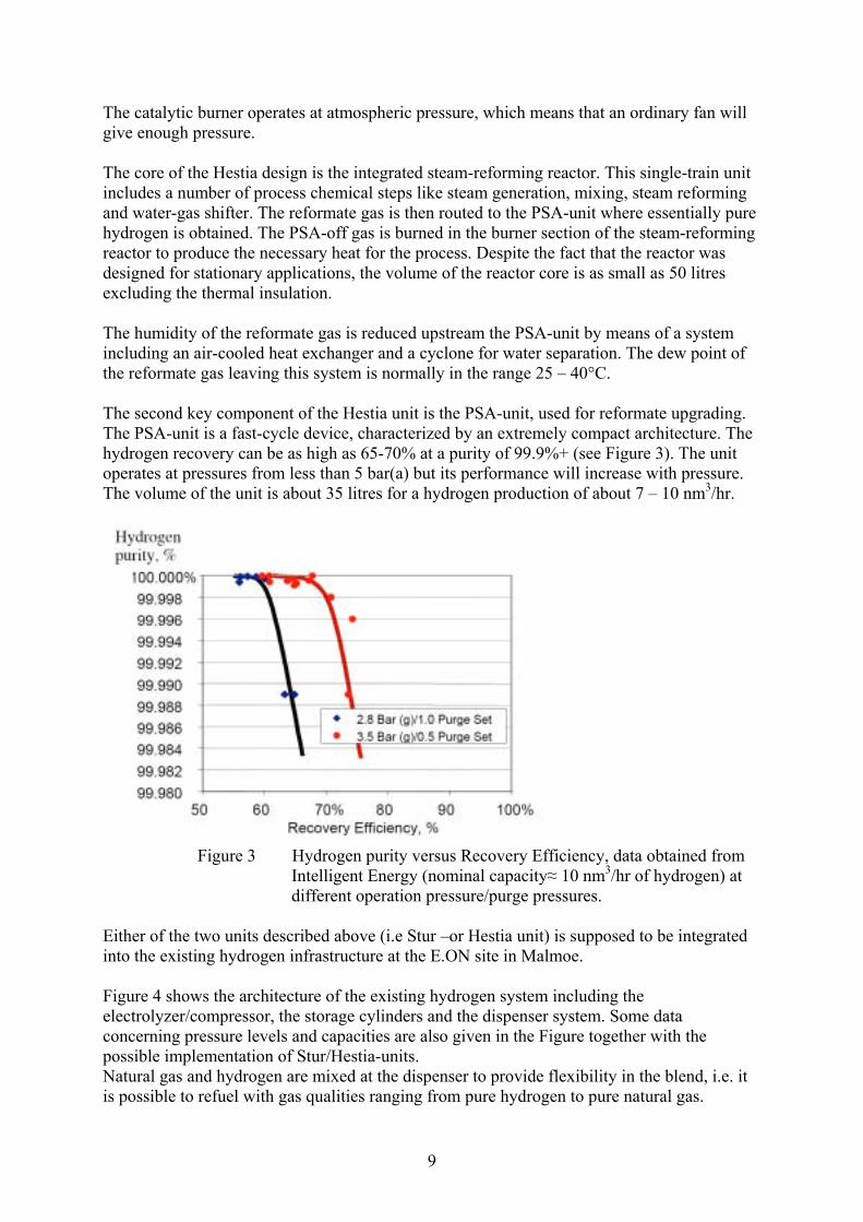
The catalytic burner operates at atmospheric pressure, which means that an ordinary fan will give enough pressure. The core of the Hestia design is the integrated steam-reforming reactor. This single-train unit includes a number of process chemical steps like steam generation, mixing, steam reforming and water-gas shifter. The reformate gas is then routed to the PSA-unit where essentially pure hydrogen is obtained. The PSA-off gas is burned in the burner section of the steam-reforming reactor to produce the necessary heat for the process. Despite the fact that the reactor was designed for stationary applications, the volume of the reactor core is as small as 50 litres excluding the thermal insulation. The humidity of the reformate gas is reduced upstream the PSA-unit by means of a system including an air-cooled heat exchanger and a cyclone for water separation. The dew point of the reformate gas leaving this system is normally in the range 25 – 40°C. The second key component of the Hestia unit is the PSA-unit, used for reformate upgrading. The PSA-unit is a fast-cycle device, characterized by an extremely compact architecture. The hydrogen recovery can be as high as 65-70% at a purity of 99.9%+ (see Figure 3). The unit operates at pressures from less than 5 bar(a) but its performance will increase with pressure. The volume of the unit is about 35 litres for a hydrogen production of about 7 – 10 nm3/hr.
Figure 3 Hydrogen purity versus Recovery Efficiency, data obtained from
Intelligent Energy (nominal capacity≈ 10 nm3/hr of hydrogen) at different operation pressure/purge pressures.
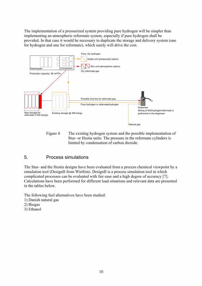
Either of the two units described above (i.e Stur –or Hestia unit) is supposed to be integrated into the existing hydrogen infrastructure at the E.ON site in Malmoe. Figure 4 shows the architecture of the existing hydrogen system including the electrolyzer/compressor, the storage cylinders and the dispenser system. Some data concerning pressure levels and capacities are also given in the Figure together with the possible implementation of Stur/Hestia-units. Natural gas and hydrogen are mixed at the dispenser to provide flexibility in the blend, i.e. it is possible to refuel with gas qualities ranging from pure hydrogen to pure natural gas.
10
The implementation of a pressurized system providing pure hydrogen will be simpler than implementing an atmospheric reformate system, especially if pure hydrogen shall be provided. In that case it would be necessary to duplicate the storage and delivery system (one for hydrogen and one for reformate), which surely will drive the cost.
Existing storage @ 390 bar(g)
Electrolyser Compressor
DispenserPure hydrogen or reformate/hydrogen
Natural gas
Mixing of NG/hydrogen/reformate isperformed in the dispenser
Hestia unit (pressurized option)
Pure, dry hydrogen
Stur unit (atmospheric option)
Dry reformate gas
Possible 2nd line for reformate gas
Production capacity: 36 nm3/hr
New storage forreformate (<200 bar(g))
Figure 4 The existing hydrogen system and the possible implementation of
Stur- or Hestia units. The pressure in the reformate cylinders is limited by condensation of carbon dioxide.
5. Process simulations The Stur- and the Hestia designs have been evaluated from a process chemical viewpoint by a simulation tool (DesignII from WinSim). DesignII is a process simulation tool in which complicated processes can be evaluated with fair ease and a high degree of accuracy [7]. Calculations have been performed for different load situations and relevant data are presented in the tables below. The following fuel alternatives have been studied: 1) Danish natural gas 2) Biogas 3) Ethanol
11
Danish natural gas has the following average composition: C1, 87 % C2, 7% C3, 3% C4, 1% C5, 0.2% C6+, 0.05% N2 0.3% CO2 1% Sulphur ≈ 5 ppm (v/v) The exact composition may vary to some extent depending on seasonal conditions. Biogas will contain 96 ± 1% methane, the balancing components being carbon dioxide, nitrogen and oxygen. The DesignII scheme of the Stur design is given in Figure 5 below. Fuel (preferably natural gas) is supplied at a low pressure (< 1 bar(g)) to the process and the burner. Water is supplied via an ion exchanger in order to provide clean water for the process. Air is supplied via a high-pressure fan to the burner of the steam reformer (stream 1) whereas a membrane pump is used to supply air to the consecutive PROX-steps (stream 24). Water is added downstream the stem -reforming unit (stream 19) in order to cool the reformate mixture and to power the water-gas shift reaction. The main stream of water is led through a number of internal heat exchanger structures to provide accurate temperature control in different parts of the system. The reformate gas must be compressed and dried before it is transferred to the gas-storage system. This can be performed in the existing compressor/dryer system or in a stand-alone installation adjacent to the Stur unit. The steam reformer will operate at temperatures ranging from 700 – 800°C, the WGS-steps at about 350°c and the PROX-steps at 100 – 120°C. The unit will be equipped with an extra liquid pump for supplying ethanol and other liquid fuels.
12
R1 R2 R3 R45HEX4X-6
MIX4
X-8
MIX3REFHEXHEX1
BURN
HEX2
MIX11 2
3
4
5
6
7 8
9 10 11 12 13 14 15 16 17 18
19MIX2
21
22 M-17
25
MIX5
DIV1
20 23
24
26
DIV3
30
31
32
33
34
R67HEX5
DIV2
27 28
29
MIX6
35
3637
38 39
COND1Compressor
HEX6COND2
40
41
4243
44
45 46
Dry reformategas
Condensate Condensate
WaterAirWaterFuel
ExhaustsFuel
Air
Figure 5 Design II scheme of the Stur design A simplified PROX-reactor with two consecutive steps is proposed for this application. Removal of two PROX- steps will simplify the overall design and increase the controllability. Table 1 summarizes important process data when processing natural gas at full load whereas Figure 6 shows the influence of the steam:carbon ratio on the hydrogen production. Table 1 Process conditions at relevant positions when processing natural gas at 100%
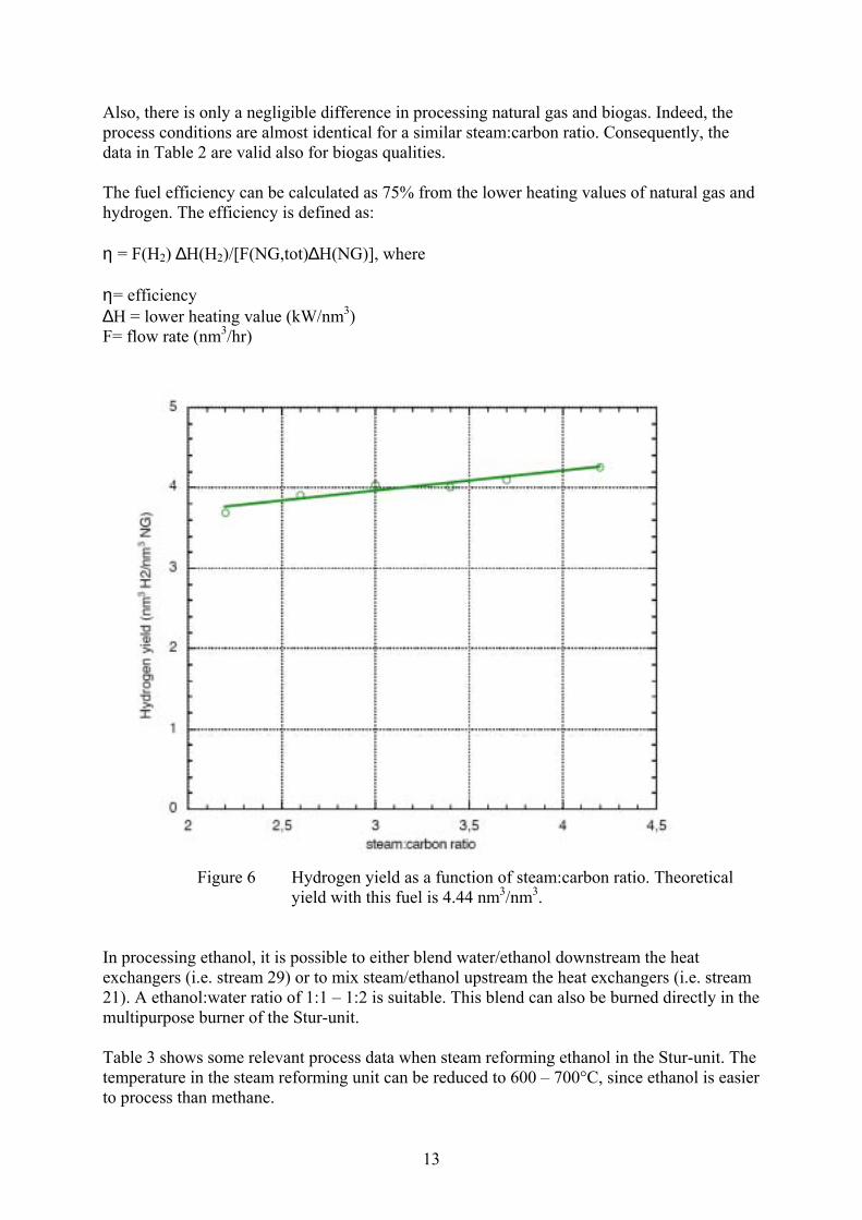
load (stream numbers, see figure 5). NG composition as above. Stream T p m V ρ H2 CO CO2 H2O CH4 NG O2 N2 No. °C kPa kg/h nm3/h kg/m3 % => => => => => => => 1 20 103 36.6 30.0 1.18 0 0 0 0 0 0 21 79 7 79 101 37.1 30.8 0.97 0 0 2.4 4.8 0 0 15.7 77.1 8 20 103 0.54 0.7 0.77 0 0 0 0 0 100 0 0 11 708 108 5.2 10.02 0.15 54.1 8.3 8.1 28.2 1.3 0 0 0 15 357 106 6.4 11.7 0.25 52.7 0.86 13.2 32.1 1.1 0 0 0 19 20 108 1.3 - 1000 0 0 0 100 0 0 0 0 21 20 110 1.2 1.5 0.77 0 0 0 0 0 100 0 0 24 20 104 0.61 0.5 1.18 0 0 0 0 0 0 21 79 29 20 110 4 - 1000 0 0 0 100 0 0 0 0 39 125 103 7.1 12.07 0.42 50.1 0 13.6 31.8 1.0 0 0 0 40 70 102 7.1 11.99 0.48 50.1 0 13.6 31.8 1.0 0 0 0 44 28 1000 4.1 8.24 4.67 73.5 0 20 0 1.5 0 0 4.9 The hydrogen yield is not sensitive to the steam:carbon ratio as can be seen in Figure 6. As the S:C ratio increases, the conversion to H2/CO2 is promoted (i.e. less methane and carbon monoxide in the reformate). However, the burner load must be increased to facilitate evaporation of the extra water. Consequently, the efficiency of the process is rather constant (scatters around 75%) for the S:C ratios studied.
13
Also, there is only a negligible difference in processing natural gas and biogas. Indeed, the process conditions are almost identical for a similar steam:carbon ratio. Consequently, the data in Table 2 are valid also for biogas qualities. The fuel efficiency can be calculated as 75% from the lower heating values of natural gas and hydrogen. The efficiency is defined as: η = F(H2) ∆H(H2)/[F(NG,tot)∆H(NG)], where η= efficiency ∆H = lower heating value (kW/nm3) F= flow rate (nm3/hr)
Figure 6 Hydrogen yield as a function of steam:carbon ratio. Theoretical
yield with this fuel is 4.44 nm3/nm3. In processing ethanol, it is possible to either blend water/ethanol downstream the heat exchangers (i.e. stream 29) or to mix steam/ethanol upstream the heat exchangers (i.e. stream 21). A ethanol:water ratio of 1:1 – 1:2 is suitable. This blend can also be burned directly in the multipurpose burner of the Stur-unit. Table 3 shows some relevant process data when steam reforming ethanol in the Stur-unit. The temperature in the steam reforming unit can be reduced to 600 – 700°C, since ethanol is easier to process than methane.
14
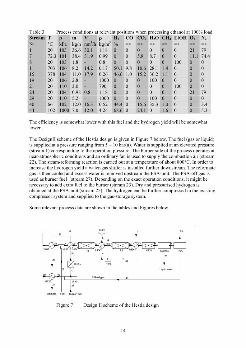
Table 3 Process conditions at relevant positions when processing ethanol at 100% load. Stream T p m V ρ H2 CO CO2 H2O CH4 EtOH O2 N2 No.. °C kPa kg/h nm3/h kg/m3 % => => => => => => => 1 20 103 36.6 30.1 1.18 0 0 0 0 0 0 21 79 7 72.3 101 38.4 31.9 0.99 0 0 5.8 8.7 0 0 11.1 74.48 20 103 1.8 - 0.8 0 0 0 0 0 100 0 0 11 703 106 8.2 14.2 0.17 50.1 9.8 10.6 28.1 1.4 0 0 0 15 378 104 11.0 17.9 0.26 46.6 1.0 15.2 36.2 1.1 0 0 0 19 20 106 2.8 - 1000 0 0 0 100 0 0 0 0 21 20 110 3.0 - 790 0 0 0 0 0 100 0 0 24 20 104 0.98 0.8 1.18 0 0 0 0 0 0 21 79 29 20 110 5.2 - 1000 0 0 0 100 0 0 0 0 40 66 102 12.0 16.3 0.52 44.4 0 15.6 35.3 1.0 0 0 3.4 44 102 1000 7.0 12.0 4.24 68.6 0 24.1 0 1.6 0 0 5.3 The efficiency is somewhat lower with this fuel and the hydrogen yield will be somewhat lower . The DesignII scheme of the Hestia design is given in Figure 7 below. The fuel (gas or liquid) is supplied at a pressure ranging from 5 – 10 bar(a). Water is supplied at an elevated pressure (stream 1) corresponding to the operation pressure. The burner side of the process operates at near-atmospheric conditions and an ordinary fan is used to supply the combustion air (stream 22). The steam-reforming reaction is carried out at a temperature of about 800°C. In order to increase the hydrogen yield a water-gas shifter is installed further downstream. The reformate gas is then cooled and excess water is removed upstream the PSA-unit. The PSA-off gas is used as burner fuel (stream 27). Depending on the exact operation conditions, it might be necessary to add extra fuel to the burner (stream 23). Dry and pressurised hydrogen is obtained at the PSA-unit (stream 25). The hydrogen can be further compressed in the existing compressor system and supplied to the gas-storage system. Some relevant process data are shown in the tables and Figures below.
R1 R2 PSAHEX2 HEX3HEX1 HEXMIX1
MIX2
DIV1BURN
HEX5 MIX3
1
2
3
4
5
6
78 9 10 11 12
16
17
18
19
20
21
22
23
24
CycloneHEX4
13 14 15
25
27
26
Pure hydrogen
Liquid water
Exhausts
PSA-off gas
Fuel Support fuel
Water
Figure 7 Design II scheme of the Hestia design
15
Table 4 Important data when processing natural gas at 100% load. NG composition as above. 70% recovery rate in the PSA-unit.
Figure 8 Effects of the recovery rate in the PSA-unit
The fuel efficiency can be calculated as 77% , which is in close agreement with the value given by Intelligent Energy (about 70%). Similar values are obtained when processing biogas whereas the efficiency is somewhat lower with ethanol. From Figure 8 it is obvious that the recovery rate in the PSA-unit is a key factor for obtaining a high overall efficiency. By manipulating the recovery rate, it is possible to balance the unit to avoid support fuel, which is an advantage from a process technical viewpoint. At low recovery rates, it is necessary to split off some of the PSA-off gas not to overheat the reactor. Consequently, the sensitivity for the overall efficiency will be more pronounced at low recovery rates.
16
Both units will produce reformate/hydrogen at a reasonable efficiency. The Stur-unit operates at atmospheric pressure, which complicates the reformate-gas management with respect to pressure and humidity. The Stur-unit is, however, more compact and has a lower thermal inertia. Both units can process all fuels of interest (natural gas, biogas ant ethanol) in addition to other possible future fuels. Some process parameters need to be adjusted according to the fuel of choice. The catalysts are chosen to provide a reasonable sulphur tolerance and it is not necessary to take out sulphur from natural gas of normal qualities. 6. Process lay-out The Stur- and Hestia designs have been drawn in a 3D-CAD program (IronCAD) to indicate the physical appearance and the size of the two units (please refer to Figure 9 – 17 below). A photo of a prototype Stur unit is shown in Figure 9 below. A prototype Hestia unit is shown in Figure 14. The Stur-unit is installed in a small cabinet with the approximate dimensions 0.6 x 0.6 x 1.2 m. The total weight is expected to be in the neighbourhood of 200 kg. The ion exchanger is located inside the cabinet and the filter tubes shall be replaced when 300 – 500 l of water have been purified (corresponding to 300 – 500 nm3 of hydrogen). The exchange of ion filters is an easy measure and an alarm indication will be obtained when the water quality becomes poor. The integral Stur-reactor is placed inside excessive insulation (thickness 1 dm) to reduce the thermal losses. All fans, pumps and valves are gathered in a special box. The electronics including the PLC-system and the separate safety system are protected from heat via a massive insulation and active cooling (via a fan). The Stur-unit is connected to a tap water line, a fuel line (preferably natural gas) and electricity (230 VAC). One outlet is for the exhausts and the other for reformate gas.
17
Figure 9 A prototype STUR unit [3]
electrical cabinet
component cabinet
Pressure sensors (air/gas), P1, P2, P4, P6
exhausts from burner
HEX2
HEX3
Igniter for burner
Fuel+air into burner
Fuel+H2O(g) into S.R.,R1
WGS, R3
PROX, R4
PROX-polisher, R4
Water pump, P1
R5 exhausts from burner+reformate +air
C2
to ventilation
18
Figure 10 Front view of the Stur unit. Footprint ≈ 0.4 m2, height≈1.2 m.
Figure 11 Side view of the Stur unit A component list is presented in Figure 12 below. The list is supplied for a comparison of different components contribution to the volume and weight. The unit must be able to start and operate at temperatures as low as –40°C. Consequently, the system must be built frost proof by the implementation of a heating circuit.
19
Figure 12 Data for relevant components in the Stur unit. Volumes and mass expressed per nm3h-1 of hydrogen produced.
Relevant data for the atmospheric Stur design are as follows: Physical data: Weight: approximately 220 kg Volume: approximately 0.5 m3 Footprint: approximately 0.4 m2 Height: approximately 1.2 m Hydrogen quality: Flow rate: 10 - 12 nm3/hr of dry reformate Quality: > 70% in hydrogen Turndown: 1:5 Start-up: <30 minutes No special purge cycle (nitrogen etc.) necessary Shutdown: No special cycle necessary Load change: 10%/minute
Operational conditions: Ambient pressure, process side (SREF/WGS/PROX) Ambient pressure, burner side SREF, 700 – 800ºC WGS, 300 - 500ºC PROX, 100 - 120ºC Utility: Electricity: 230 VAC Water supply: quality (< 5 µS/cm, preferably < 1 µS/cm) Frost proof design Control system: Included Safety system: Included Lifetime: Catalyst 8,000 hrs (guarantee), 3 – 5 years expected In addition, the atmospheric system shall be equipped with a reformate compressor and a dryer system. Two possible options exist: a) to deliver a stand-alone unit for this function or b) to use the existing system in the electrolysis appliance including compressor and dryer. The most difficult part is to find a unit small enough for this application. A rebuilt air compressor might be used together with a membrane dryer [8]. Figure 13 below shows a scheme of a compressor/dryer system for this application. The most space consuming components are the low-and high-pressure tanks for reformate gas.
Figure 13 Compressor/dryer system. Suitable compressors can be found from suppliers like Bitzer, Rix and Kaeser[10, 11, 12] The membrane dryer can be purchased from Kaeser [12]. Even if the components in this system are relatively cheap it will bring undesired complexity to the system, which might affect the reliability and robustness. Consequently it is recommended to use the existing compressor/dryer system, if possible. The Hestia-unit is somewhat larger and heavier than the Stur-unit. The system can be installed in a cabinet with the approximate dimensions of 0.6 x 0.8 x 1.6 m. The weight is calculated at about 300 kg. The most important components are the pressurised steam-reforming unit and the fast-cycle PSA unit.
Storage tank,low pressure
Compressor
Membrane dryer
Storage tank,high pressure
Cooler
Drain
Reformateinlet
DrainOff gas, mainlywater/CO2
Reformate @ 5 - 10 bar(a)
21
The system will operate at a pressure of 5 – 10 bar(a) on the process side and at atmospheric conditions on the burner side. Tap water and fuel (preferably natural gas) are supplied to the unit and exhausts and pure hydrogen is delivered from the unit. Electricity (230 VAC) is needed for the operation (not necessary if a fuel cell is installed for grid disconnected operation). The control- and safety system will be of the same complexity as in the Stur-unit. Excessive thermal insulation will be supplied to reduce the thermal losses and to protect sensitive components. A safety-relief valve is installed since the reactors are contained in a pressure vessel.
Figure 14 Prototype Hestia unit [4] Figure 15 and 16 show a possible arrangement of the relevant components. Figure 17 lists the most important components in order to be able to present size- and weight data.
22
Figure 15 Possible front view of the Hestia unit. Footprint≈0.5 m2, height≈1.6 m.
Figure 16 Possible side view of the Hestia unit Data for relevant components in the Hestia unit are given in Figure 17 for comparison purposes.
23
Figure 17 Data for possible components in the Hestia unit. Volume and mass expressed per nm3h-1 of hydrogen produced.
Relevant data for the pressurized system are as follows: Physical data: Weight: approximately 300 kg Volume: approximately 0.8 m3 Footprint: approximately 0.5 m2 Height: approximately 1.6 m Hydrogen quality: Flow rate: 7 nm3/hr of hydrogen Quality: 99 – 99.9% in hydrogen Turndown: 1:5 Start-up: 60 minutes No special purge cycle (nitrogen etc.) necessary Shutdown: No special cycle necessary Load change: 5%/minute
Component V(l/nm3hr-1)
m(kg/ nm3hr-1)
Type
ReactorsSREF/WGS 6.9 21 Catator- Intelligent EnergyPSA 3.5 2 Via Intelligent Energy
Heat exchangersGas recuperator 0.2 0.4 SWEP B8 x 40Condenser 11 3 Swedcoil special
TransportPump, water 0.2 0.2 e.g.GPAPump, fuel 0.2 0.2 e.g.GPAFan 0.1 0.1 e.g. Ametek 119379ValvesIon exchanger
Operational conditions: 5 – 10 bar(g), process side (SREF/WGS) Ambient pressure, burner side SREF, 700 – 800ºC WGS, 300 - 500ºC PSA, <50ºC Utility: Electricity: 230 VAC Water supply: quality (< 5 µS, preferably < 1 µS) Frost proof design Control system: Included Safety system: Included Lifetime: Catalyst 8,000 hrs (guarantee), 3 – 5 years expected The Stur-unit is somewhat smaller than the Hestia-unit and its weight is less. However, since this a stationary application, these figures are of less importance. The systems are considered to be of approximately the same technical complexity. The Hestia-unit will provide pure hydrogen at an elevated pressure, whereas the Stur-unit only will supply humid reformate gas. Consequently, it might be necessary to equip the Stur-unit with a compressor/dryer-system. 7. Control and safety P/I diagrams for the two systems are presented in Figure 18 and 19. The control strategy and procedures for start-up/shut down are also discussed in this section. Figure 18 shows all catalytic steps of the Stur-system together with all relevant control loops. The load regulator will be set by an electric signal (4-20 mA or 0 – 10 V). This signal will adjust the fuel flow to the process (valve PV1). The water- and the air flow to the process are also set by the load regulator. Consequently the ratio between fuel, water (steam) and air will be constant at all loads. The heat-generation system (i.e. the burner) works autonomously. When the load is increased more heat will be removed from the process and the outlet temperature (on the burner side) will decrease. The system will respond by increasing the fuel supply to the burner (PV2). In order not to overheat the inlet of the steam reformer, the speed of the fan (F1) is increased until the temperature T2 is in balance. To accomplish a stable combustion, it is advisable to carry out the combustion at a slightly lower lambda value than the one corresponding to the inlet conditions. Consequently a split function (CV1) is implemented to adjust for a stable combustion.
25
There are a number of temperature regulators installed in the water circuit to provide optimum conditions for the catalysts. Water is supplied to subsequent internal heat exchangers in the PROX-section. Temperature control is by means of solenoid valves opening on demand. If no cooling is necessary the water is by passed over the PROX section. In this application, it will be enough to install two PROX-steps. Additional PROX-steps can be of importance if the reformate gas must reach fuel-cell quality. Temperature control in the WGS-section is accomplished in the same manner via SV1 and SV2. The air is split between the consecutive PROX-steps by means of a fixed ratio. Temperature control is by means of the coolant.
Mix
Mix
MixSREF-unit
Mix
WGS-unit
Mix MixMixMix
PROX-unit
Mix
Mix
SREF WGS1 WGS2
PROX1PROX2PROX3PROX4
HEX1
HEX2
HEX3 HEX4 HEX5
HEX6HEX7HEX8HEX9
P1
P2
Fan1
Fan2
SV1 SV2
PV1
PV2
CV1
CV2
CV4 CV5 CV6 CV7
NG
NG
Water
Water
Air
BURN
CV3SV3 SV4 SV5
TAC
TA
TA
TAC
TAC
TAC TACTAC TAC
TAC
T 1
T 2
T 3
TAC T 4 T 5
T 6
T 7T 8T 9T 1 0
T 3
T 4
T 5 T 6
T 7T 8T 9FAC
FAC
FAC
F 1
F 1
F 3
F 3
F 2
F 2
T 1
Reformate
Figure 18 P/I-diagram, atmospheric unit (Stur), equipped with four PROX-steps.
During start-up, air and fuel are supplied to the burner at fixed flow rates. When the outlet temperature (T3) is high enough, the water supply and the air supply are ramped up. Following a small lag time (determined during the commissioning work) the fuel supply is started. The algorithm is then transferred into automatic control, as described above. During shut down the fuel supply to the process side is stopped. Since less heat is subtracted from the system, T3 will increase and the fuel supply to the burner will decrease. The water supply is then stopped together with the fuel supply to the burner. Finally, the air supply to the burner and the consecutive PROX-steps are stopped.
26
In order to speed up the start-up and shut down processes, it is possible to install a gas re- circulation system, which effectively transports the heat through the reactor system. Although the system might look complicated in the P/I-diagram, it is in fact relatively simple in its construction and in operation. The safety system will include temperature alarms in the reactor train and in the burner. Pressure indicators will be installed to indicate possible malfunction of fans and pumps. A gas alarm will be installed to detect possible leakage of hydrogen/reformate. The alarm/safety system will be individual and separated from the control system. Even simpler is the pressurised system, the Hestia unit. Exactly as in the Stur-unit, the burner operates autonomously and independent of the process. When the load is increased, the process will subtract more heat from the system and the temperature at the outlet of the burner (T2) will decrease. More fuel is then supplied via PV3 and the temperature will increase. The speed of the air blower will simultaneously increase to reduce the inlet temperature to the process (T1). The water supply is also set by the load regulator to provide a constant ratio between fuel and water to the system, independent of the load. In this system, it is possible to recover the heat in the PSA-off gas by burning it in the heat generator. Pure hydrogen is supplied at elevated pressure, whereas the PSA-off gas is delivered at near-atmospheric conditions to the burner. When starting the unit, air and fuel (natural gas) are supplied to the burner. When the temperature has increased to the set-point, water is supplied and following a lag time, also the fuel on the process side. The unit is then put into automatic load control. The system pressure is then increased gradually to reach the desired value. Shut down is reversed to the start-up scheme. The pressure is reduced to atmospheric level and the fuel supply is cut. As a consequence, the burner load will decrease. The next step is to stop the water supply and then finally to stop the burner.
27
Mix
P1
Fan1Mix
HEX1 SREF WGS R3
HEX2
HEX3
HEX5
BURN
Exhausts NG NG
99.9%+ H2
PREF & PWGS
PSA offgas
PV1
CV1
PV2 PV3
Fan2
HEX4
PSA-unit
Cyclone separator
Mix
Water
TAC
FAC
FACTAC
TAC
F 1
F 2
T 1
T 2
T 3
T 4
F 1
F 2
T 2T 1
T 3TA
Air
Figure 19 P/I-diagram, pressurized unit (Hestia) The safety system, which is separated from the control system, will include temperature alarms and flow indicators. A gas detector will be installed to identify a possible leakage of hydrogen/reformate. The pressure vessel is equipped with a safety relief valve. 8. Applicable regulations and Certification All hydrogen and fuel cell products, which are sold or put into service for the first time within the European Union must bear a CE mark. Sine CE-marking of hydrogen generators and fuel cell system is new, it is not always clear which regulations one shall follow. The relevant European Directives are [9]: - Gas Appliance Directive (GAD, 90/396/EEG) - Low voltage Directive (LVD, 73/22/EG) - Electromagnetic Compatibility Directive (EMC-D, 89/336/EEG) - Machinery Directive (MD, 98/37/EG) - Pressure Equipment Directive (PED, 97/23/EG) - Explosive Atmospheres Directives (ATEX-D, 94/9/EC, 1999/92/EC) The Gas Appliance Directive (GAD) focuses on safe utilization of gaseous fuels. The following aspects are assessed:
a) Construction b) Gas technology (emissions, efficiency) c) Safety and electronics – internal failure behaviour
d) Immunity to electromagnetic radiation e) Electrical safety This directive is a “third party” directive and the involvement of a notified body is required.
28
The Low Voltage Directive (LVD) applies to units in which a current is applied at 50 – 1000 VAC or 75 – 1500 VDC. The directive focuses on electrical safety. The manufacturer´s self declaration shall show that the unit complies with the harmonized European Norms (EN). The manufacturer can also prove that the product complies with the essential requirements of the directive by performing tests at a competent body (third-part laboratory tests). This directive does not require certification through a notified body. The Electromagnetic Compatibility Directive (EMC-D) is applicable to appliances capable of generating electromagnetic disturbance or appliances, where the function can be affected by external electromagnetic disturbances. As with the Low Voltage Directive, the marking is based on the declaration of the manufacturer, taking the harmonized European norms into account. If the norms are not followed completely, it is possible to perform a third-party test through a competent body to verify that product complies with the essential requirements of the directive. The EMC-D directive does not require certification through a notified body. The Machinery Directive (MD) is in principle applicable to all appliances with moving parts. CE-marking according to the MD can be based on the self declaration of the manufacturer. MD does not add more demands on gas safety than the GAD and normally the norms under GAD can be used to show gas technical safety. The Pressure Equipment Directive (PED) is applicable to appliances including liquids or gases with an internal pressure of at least 0.5 bar(g). The requirements of the PED will increase as the volume and/or pressure increase. Moreover, the requirements also depend on the nature of the liquid/gas (flammability, toxicity). As with the GAD, the PED is subject to the involvement of a “notified body”, i.e. the PED is a third-party directive. The Explosive Atmosphere Directives (ATEX-D) deals with a) the safety and health protection of workers in various classifications of explosive zones and b) equipment and protective systems intended for use in potentially explosive atmospheres. The zone classification is based on IEC-EN 60079-10. The atmospheric unit will be subject to all directives apart from the PED. All six directives in the list above will be applicable to the pressurized unit. A notified body as ÅF KONTROLL will perform the CE-marking according to the PED, whereas it will be difficult to find a “notified body” for the GAD in Sweden. However, there are organisations in Denmark, Germany (tüv) and the Netherlands (Gastec) capable of performing this certification work. 9. Realization plan Project phases This chapter will provide information of the possible realization of a refuelling project with respect to the time schedule and the associated costs. The refuelling project is divided into two major phases, a) construction-, delivery- and commissioning and b) evaluation phase. a) Construction-, delivery- and commissioning phase
29
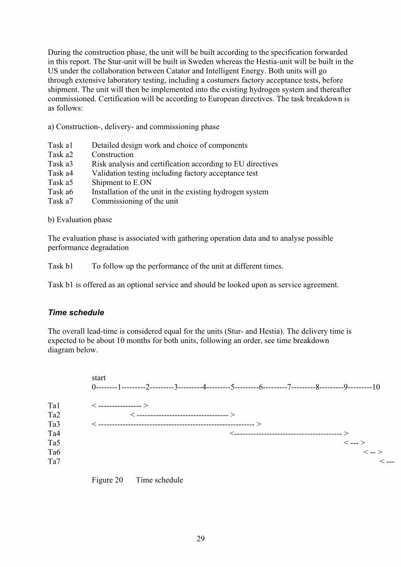
During the construction phase, the unit will be built according to the specification forwarded in this report. The Stur-unit will be built in Sweden whereas the Hestia-unit will be built in the US under the collaboration between Catator and Intelligent Energy. Both units will go through extensive laboratory testing, including a costumers factory acceptance tests, before shipment. The unit will then be implemented into the existing hydrogen system and thereafter commissioned. Certification will be according to European directives. The task breakdown is as follows: a) Construction-, delivery- and commissioning phase Task a1 Detailed design work and choice of components Task a2 Construction Task a3 Risk analysis and certification according to EU directives Task a4 Validation testing including factory acceptance test Task a5 Shipment to E.ON Task a6 Installation of the unit in the existing hydrogen system Task a7 Commissioning of the unit b) Evaluation phase The evaluation phase is associated with gathering operation data and to analyse possible performance degradation Task b1 To follow up the performance of the unit at different times. Task b1 is offered as an optional service and should be looked upon as service agreement. Time schedule The overall lead-time is considered equal for the units (Stur- and Hestia). The delivery time is expected to be about 10 months for both units, following an order, see time breakdown diagram below. start
Budget cost The deliverables include: - The hardware (Stur-or Hestia unit) - Technical documentation - Service- and maintenance manuals - Performance verification and installation/commissioning - Stur unit, SEK ≈ 3,700,000 - Hestia unit, SEK ≈ 4,800,000 - Service agreement SEK/yr ≈ 120,000 Scheduled service activities are: - Measurement of gas quality and gas production (once every two months) - Catalyst replacement (if necessary) - Technical check of auxiliary components A detailed offer will be supplied to E.ON on request. 10 Conclusions In this report, two suitable system solutions have been presented for the refuelling station project. The atmospheric unit (abbreviated Stur-unit) will produce a reformate type gas, carrying carbon oxides, methane and nitrogen in addition to hydrogen. The reformate gas shall be dehumidified down to a dew point of –50°C. The pressurized unit (abbreviated Hestia-unit) will operate at 5 – 10 bar(a) and will produce pure hydrogen (99.9%+) at the operating pressure by the use of a complementary PSA-system. The Stur- and the Hestia units are equal in size and weight and they are considered equal also from a safety- and maintenance perspective. Delivery times are equal and approximately the same certification work will apply (apart from the Pressure Equipment Directive which is only applicable to the Hestia unit). The thermal efficiencies are equal even if this figure is of less importance in this application. Fuel flexibility can be built into both systems. The thermal response of the Stur-unit is, however, better than the Hestia-unit due to differences in the thermal inertia. Both units have been successfully demonstrated in fully automatic operation, also in long-term tests. The cost of the Hestia unit is about 25% higher than the corresponding cost of the Stur-unit. However, the differences in price must be related to the differences in technical performance. If it is considered important to produce pure hydrogen, the Hestia unit should be the recommended choice. It is also possible to equip this unit with a small fuel cell to provide electricity for internal use. Also, the overall implementation of the Hestia-unit into the existing system is easier. A dry and pure hydrogen stream will reach the compressor system at elevated pressures and there is no need to separate hydrogen and reformate qualities in the storage system. The Stur unit will demand a duplicate storage/delivery system since the gas qualities will differ.
31
If it is enough to produce dry reformate gas and if it is acceptable to mix hydrogen and reformate gas, the Stur unit should be the recommended choice. It is somewhat cheaper and simpler, especially if the number of PROX-steps could be reduced. 11. References 1. F. Silversand, “Fuel processor for mall-scale production of hydrogen –
Experimental study”, SGC report no. 130, October 2003, part 1. 2. F. Silversand, “Fuel processor for mall-scale production of hydrogen –
Experimental study”, SGC report no. 130, October 2003, part 2. 3. A-K. Jannasch and F. Silversand, “Reliability study of a small-scale fuel processor system (STUR-10 kWH2), SGC report no. 151, December 2004. 4. www.intelligent-energy.com 5. www.hytrec.no 6. Gasteknik, 2004(1), s. 16. 7. www.winsim.com 8. www.kaeser.com 9. F. Thuis, “European Certification of Hydrogen Generators and Fuel Cell
Systems”, Proc. of the Fuel Cell Seminar 2004, San Antoio, s. 201. 10. www. bitzer.de 11. www.rixindustries.com 12. www.kaeser.com