Region Proposal by Guided Anchoring Jiaqi Wang 1* Kai Chen 1* Shuo Yang 2 Chen Change Loy 3 Dahua Lin 1 1 CUHK - SenseTime Joint Lab, The Chinese University of Hong Kong 2 Amazon Rekognition 3 Nanyang Technological University {wj017,ck015,dhlin}@ie.cuhk.edu.hk [email protected][email protected]Abstract Region anchors are the cornerstone of modern object detection techniques. State-of-the-art detectors mostly rely on a dense anchoring scheme, where anchors are sampled uniformly over the spatial domain with a predefined set of scales and aspect ratios. In this paper, we revisit this foun- dational stage. Our study shows that it can be done much more effectively and efficiently. Specifically, we present an alternative scheme, named Guided Anchoring, which lever- ages semantic features to guide the anchoring. The pro- posed method jointly predicts the locations where the cen- ter of objects of interest are likely to exist as well as the scales and aspect ratios at different locations. On top of predicted anchor shapes, we mitigate the feature incon- sistency with a feature adaption module. We also study the use of high-quality proposals to improve detection per- formance. The anchoring scheme can be seamlessly inte- grated into proposal methods and detectors. With Guided Anchoring, we achieve 9.1% higher recall on MS COCO with 90% fewer anchors than the RPN baseline. We also adopt Guided Anchoring in Fast R-CNN, Faster R-CNN and RetinaNet, respectively improving the detection mAP by 2.2%, 2.7% and 1.2%. Code will be available at https: //github.com/open-mmlab/mmdetection. 1. Introduction Anchors are regression references and classification can- didates to predict proposals (for two-stage detectors) or final bounding boxes (for single-stage detectors). Modern object detection pipelines usually begin with a large set of densely distributed anchors. Take Faster RCNN [27], a popular ob- ject detection framework, for instance, it first generates re- gion proposals from a dense set of anchors and then classi- fies them into specific classes and refines their locations via bounding box regression. There are two general rules for a reasonable anchor de- * Equal contribution. sign: alignment and consistency. Firstly, to use convo- lutional features as anchor representations, anchor centers need to be well aligned with feature map pixels. Secondly, the receptive field and semantic scope should be consistent with the scale and shape of anchors on different locations of a feature map. The sliding window is a simple and widely adopted anchoring scheme following the rules. For most de- tection methods, the anchors are defined by such a uniform scheme, where every location in a feature map is associated with k anchors with predefined scales and aspect ratios. Anchor-based detection pipelines have been shown ef- fective in both benchmarks [6, 20, 7, 5] and real-world sys- tems. However, the uniform anchoring scheme described above is not necessarily the optimal way to prepare the an- chors. This scheme can lead to two difficulties: (1) A neat set of anchors of fixed aspect ratios has to be predefined for different problems. A wrong design may hamper the speed and accuracy of the detector. (2) To maintain a sufficiently high recall for proposals, a large number of anchors are needed, while most of them correspond to false candidates that are irrelevant to the object of interests. Meanwhile, a large number of anchors can lead to significant computa- tional cost especially when the pipeline involves a heavy classifier in the proposal stage. In this work, we present a more effective method to pre- pare anchors, with the aim to mitigate the issues of hand- picked priors. Our method is motivated by the observation that objects are not distributed evenly over the image. The scale of an object is also closely related to the imagery con- tent, its location and geometry of the scene. Following this intuition, our method generates sparse anchors in two steps: first identifying sub-regions that may contain objects and then determining the shapes at different locations. Learnable anchor shapes are promising, but it breaks the aforementioned rule of consistency, thus presents a new challenge for learning anchor representations for accurate classification and regression. Scales and aspect ratios of an- chors are now variable instead of fixed, so different feature map pixels have to learn adaptive representations that fit the corresponding anchors. To solve this problem, we introduce arXiv:1901.03278v2 [cs.CV] 12 Apr 2019
Region anchors are the cornerstone of modern objectdetection techniques. State-of-the-art detectors mostly relyon a dense anchoring scheme, where anchors are sampleduniformly over the spatial domain with a predefined set ofscales and aspect ratios. In this paper, we revisit this foun-dational stage. Our study shows that it can be done muchmore effectively and efficiently. Specifically, we present analternative scheme, named Guided Anchoring, which lever-ages semantic features to guide the anchoring. The pro-posed method jointly predicts the locations where the cen-ter of objects of interest are likely to exist as well as thescales and aspect ratios at different locations. On top ofpredicted anchor shapes, we mitigate the feature incon-sistency with a feature adaption module. We also studythe use of high-quality proposals to improve detection per-formance. The anchoring scheme can be seamlessly inte-grated into proposal methods and detectors. With GuidedAnchoring, we achieve 9.1% higher recall on MS COCOwith 90% fewer anchors than the RPN baseline. We alsoadopt Guided Anchoring in Fast R-CNN, Faster R-CNNand RetinaNet, respectively improving the detection mAP by2.2%, 2.7% and 1.2%. Code will be available at https://github.com/open-mmlab/mmdetection.
1. Introduction
Anchors are regression references and classification can-didates to predict proposals (for two-stage detectors) or finalbounding boxes (for single-stage detectors). Modern objectdetection pipelines usually begin with a large set of denselydistributed anchors. Take Faster RCNN [27], a popular ob-ject detection framework, for instance, it first generates re-gion proposals from a dense set of anchors and then classi-fies them into specific classes and refines their locations viabounding box regression.
There are two general rules for a reasonable anchor de-
∗Equal contribution.
sign: alignment and consistency. Firstly, to use convo-lutional features as anchor representations, anchor centersneed to be well aligned with feature map pixels. Secondly,the receptive field and semantic scope should be consistentwith the scale and shape of anchors on different locations ofa feature map. The sliding window is a simple and widelyadopted anchoring scheme following the rules. For most de-tection methods, the anchors are defined by such a uniformscheme, where every location in a feature map is associatedwith k anchors with predefined scales and aspect ratios.
Anchor-based detection pipelines have been shown ef-fective in both benchmarks [6, 20, 7, 5] and real-world sys-tems. However, the uniform anchoring scheme describedabove is not necessarily the optimal way to prepare the an-chors. This scheme can lead to two difficulties: (1) A neatset of anchors of fixed aspect ratios has to be predefined fordifferent problems. A wrong design may hamper the speedand accuracy of the detector. (2) To maintain a sufficientlyhigh recall for proposals, a large number of anchors areneeded, while most of them correspond to false candidatesthat are irrelevant to the object of interests. Meanwhile, alarge number of anchors can lead to significant computa-tional cost especially when the pipeline involves a heavyclassifier in the proposal stage.
In this work, we present a more effective method to pre-pare anchors, with the aim to mitigate the issues of hand-picked priors. Our method is motivated by the observationthat objects are not distributed evenly over the image. Thescale of an object is also closely related to the imagery con-tent, its location and geometry of the scene. Following thisintuition, our method generates sparse anchors in two steps:first identifying sub-regions that may contain objects andthen determining the shapes at different locations.
Learnable anchor shapes are promising, but it breaks theaforementioned rule of consistency, thus presents a newchallenge for learning anchor representations for accurateclassification and regression. Scales and aspect ratios of an-chors are now variable instead of fixed, so different featuremap pixels have to learn adaptive representations that fit thecorresponding anchors. To solve this problem, we introduce
an effective module to adapt the features based on anchorgeometry.
We formulate a Guided Anchoring Region Proposal Net-work (GA-RPN) with the aforementioned guided anchoringand feature adaptation scheme. Thanks to the dynamicallypredicted anchors, our approach achieves 9.1% higher re-call with 90% substantially fewer anchors than the RPNbaseline that adopts dense anchoring scheme. By predict-ing the scales and aspect ratios instead of fixing them basedon a predefined list, our scheme handles tall or wide ob-jects more effectively. Besides region proposals, the guidedanchoring scheme can be easily integrated into any de-tectors that depend on anchors. Consistent performancegains can be achieved with our scheme. For instance,GA-Fast-RCNN, GA-Faster-RCNN and GA-RetinaNet im-prove overall mAP by 2.2%, 2.7% and 1.2% respectivelyon COCO dataset over their baselines with sliding windowanchoring. Furthermore, we explore the use of high-qualityproposals, and propose a fine-tuning schedule using GA-RPN proposals, which can improve the performance of anytrained models, e.g., it improves a fully converged FasterR-CNN model from 37.4% to 39.6%, in only 3 epochs.
The main contributions of this work lie in several as-pects. (1) We propose a new anchoring scheme with theability to predict non-uniform and arbitrary shaped anchorsother than dense and predefined ones. (2) We formulatethe joint anchor distribution with two factorized conditionaldistributions, and design two modules to model them re-spectively. (3) We study the importance of aligning fea-tures with the corresponding anchors and design a featureadaption module to refine features based on the underlyinganchor shapes. (4) We investigate the use of high-qualityproposals for two-stage detectors and propose a scheme toimprove the performance of trained models.
2. Related WorkSliding window anchors in object detection. Generat-ing anchors with the sliding window manner in featuremaps has been widely adopted by anchor-based variousdetectors. The two-stage approach has been the leadingparadigm in the modern era of object detection. Faster R-CNN [27] proposes the Region Proposal Network (RPN)to generates object proposals. It uses a small fully con-volutional network to map each sliding window anchor toa low-dimensional feature. This design is also adopted inlater two-stage methods [3, 18, 12]. MetaAnchor [32] in-troduces meta-learning to anchor generation. There havebeen attempts [8, 9, 23, 31, 33, 34, 1, 2] that apply cas-cade architecture to reject easy samples at early layers orstages, and regress bounding boxes iteratively for progres-sive refinement. Compared to two-stage approaches, thesingle-stage pipeline skips object proposal generation andpredicts bounding boxes and class scores in one evaluation.
Although the proposal step is omitted, single-stage meth-ods still use anchor boxes produced by the sliding window.For instance, SSD [21] and DenseBox [14] generate anchorsdensely from feature maps and evaluate them like a multi-class RPN. RetinaNet [19] introduces focal loss to addressthe foreground-background class imbalance. YOLOv2[26]adopt sliding window anchors for classification and spatiallocation prediction so as to achieve a higher recall than itsprecedent.Comparison and difference. We summarize the differ-ences between the proposed method and conventional meth-ods as follows. (i) Primarily, previous methods (single-stage, two-stage and multi-stage) still rely on dense anduniform anchors by sliding window. We discard the slid-ing window scheme and propose a better counterpart toguide the anchoring and generate sparse anchors, whichhas not been explored before. (ii) Cascade detectors adoptmore than one stage to refine detection bounding boxes pro-gressively, which usually leads to more model parametersand a decrease in inference speed. These methods adoptRoI Pooling or RoI Align to extract aligned features forbounding boxes, which is too expensive for proposal gen-eration or single-stage detectors. (iii) Anchor-free meth-ods [14, 15, 25] usually have simple pipelines and producefinal detection results within a single stage. Due to the ab-sence of anchors and further anchor-based refinement, theylack the ability to deal with complex scenes and cases. Ourfocus is the sparse and non-uniform anchoring scheme anduse of high-quality proposals to boost the detection perfor-mance. Towards this goal, we have to solve the misalign-ment and inconsistency issues which are specific to anchor-based methods. (iv) Some single-shot detectors [33, 30] re-fine anchors by multiple regression and classification. Ourmethod differs from them significantly. We do not refine an-chors progressively, instead, we predict the distribution ofanchors, which is factorized as locations and shapes. Con-ventional methods fail to consider the alignment betweenanchors and features so they regress anchors (represented by[x, y, w, h]) for multiple times and breaks the alignment aswell as consistency. On the contrary, we emphasize the im-portance of the two rules, so we only predict anchor shapesbut fix anchor centers and adapt features based on the pre-dicted shapes.
3. Guided AnchoringAnchors are the basis in modern object detection
pipelines. Mainstream frameworks, including two-stageand single-stage methods, mostly rely on a uniform arrange-ment of anchors. Specifically, a set of anchors with prede-fined scales and aspect ratios will be deployed over a fea-ture map of size W × H , with a stride of s. This schemeis inefficient, as many of the anchors are placed in regionswhere the objects of interest are unlikely to exist. In addi-
W×H×1
location
shape
feature pyramid
𝒩𝐿
W×H×2
Feature adaption
Anchor generation
1x1 conv
offset field
anchors𝒩𝑆
𝒩T
Guided anchoring
anchorsprediction
anchorspredictionGuided
anchoring
anchorspredictionGuided
anchoring
anchorspredictionGuided
anchoring
Guided anchoring
𝐹𝐼
𝐹𝐼′
Figure 1: An illustration of our framework. For each output feature map in the feature pyramid, we use an anchor generation module withtwo branches to predict the anchor location and shape, respectively. Then a feature adaption module is applied to the original feature mapto make the new feature map aware of anchor shapes.
tion, such hand-picked priors unrealistically assume a set offixed shape (i.e., scale and aspect ratio) for objects.
In this work, we aim to develop a more efficient anchor-ing scheme to arrange the anchors with learnable shapes,considering the non-uniform distribution of objects’ loca-tions and shapes. The guided anchoring scheme works asfollows. The location and the shape of an object can becharacterized by a 4-tuple in the form of (x, y, w, h), where(x, y) is the spatial coordinate of the center, w the width,and h the height. Suppose we draw an object from a givenimage I , then its location and shape can be considered tofollow a distribution conditioned on I , as follows:
p(x, y, w, h|I) = p(x, y|I)p(w, h|x, y, I). (1)
This factorization captures two important intuitions: (1)given an image, objects may only exist in certain regions;and (2) the shape, i.e., scale and aspect ratio, of an objectclosely relates to its location.
Following this formulation, we devise an anchor gener-ation module as shown in the red dashed box of Figure 1.This module is a network comprised of two branches for lo-cation and shape prediction, respectively. Given an image I ,we first derive a feature map FI . On top of FI , the locationprediction branch yields a probability map that indicates thepossible locations of the objects, while the shape predic-tion branch predicts location-dependent shapes. Given theoutputs from both branches, we generate a set of anchorsby choosing the locations whose predicted probabilities areabove a certain threshold and the most probable shape ateach of the chosen locations. As the anchor shapes can vary,the features at different locations should capture the visualcontent within different ranges. With this taken into consid-eration, we further introduce a feature adaptation module,which adapts the feature according to the anchor shape.
The anchor generation process described above is basedon a single feature map. Recent advances in object detec-
tion [18, 19] show that it is often helpful to operate on mul-tiple feature maps at different levels. Hence, we developa multi-level anchor generation scheme, which collects an-chors at multiple feature maps, following the FPN architec-ture [18]. Note that in our design, the anchor generationparameters are shared across all involved feature levels thusthe scheme is parameter-efficient.
3.1. Anchor Location Prediction
As shown in Figure 1, the anchor location predictionbranch yields a probability map p(·|FI) of the same size asthe input feature map FI , where each entry p(i, j|FI) corre-sponds to the location with coordinate ((i+ 1
2 )s, (j +12 )s)
on I , where s is stride of the feature map, i.e., the distancebetween neighboring anchors. The entry’s value indicatesthe probability of an object’s center existing at that location.
In our formulation, the probability map p(i, j|FI) is pre-dicted using a sub-network NL. This network applies a1 × 1 convolution to the base feature map FI to obtain amap of objectness scores, which are then converted to prob-ability values via an element-wise sigmoid function. Whilea deeper sub-network can make more accurate predictions,we found empirically that a convolutional layer followedby a sigmoid transform strikes a good balance between ef-ficiency and accuracy.
Based on the resultant probability map, we then deter-mine the active regions where objects may possibly existby selecting those locations whose corresponding probabil-ity values are above a predefined threshold εL. This pro-cess can filter out 90% of the regions while still maintain-ing the same recall. As illustrated in Figure 4(b), regionslike sky and ocean are excluded, while anchors concentratedensely around persons and surfboards. Since there is noneed to consider those excluded regions, we replace the en-suing convolutional layers by masked convolution [17, 28]for more efficient inference.
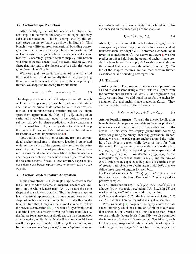
3.2. Anchor Shape Prediction
After identifying the possible locations for objects, ournext step is to determine the shape of the object that mayexist at each location. This is accomplished by the an-chor shape prediction branch, as shown in Figure 1. Thisbranch is very different from conventional bounding box re-gression, since it does not change the anchor positions andwill not cause misalignment between anchors and anchorfeatures. Concretely, given a feature map FI , this branchwill predict the best shape (w, h) for each location, i.e., theshape that may lead to the highest coverage with the nearestground-truth bounding box.
While our goal is to predict the values of the widthw andthe height h, we found empirically that directly predictingthese two numbers is not stable, due to their large range.Instead, we adopt the following transformation:
w = σ · s · edw, h = σ · s · edh. (2)
The shape prediction branch will output dw and dh , whichwill then be mapped to (w, h) as above, where s is the strideand σ is an empirical scale factor (σ = 8 in our experi-ments). This nonlinear transformation projects the outputspace from approximate [0, 1000] to [−1, 1], leading to aneasier and stable learning target. In our design, we use asub-network NS for shape prediction, which comprises a1 × 1 convolutional layer that yields a two-channel mapthat contains the values of dw and dh, and an element-wisetransform layer that implements Eq.(2).
Note that this design differs essentially from the conven-tional anchoring schemes in that every location is associatedwith just one anchor of the dynamically predicted shape in-stead of a set of anchors of predefined shapes. Our experi-ments show that due to the close relations between locationsand shapes, our scheme can achieve much higher recall thanthe baseline scheme. Since it allows arbitrary aspect ratios,our scheme can better capture those extremely tall or wideobjects.
3.3. Anchor-Guided Feature Adaptation
In the conventional RPN or single stage detectors wherethe sliding window scheme is adopted, anchors are uni-form on the whole feature map, i.e., they share the sameshape and scale in each position. Thus the feature map canlearn consistent representation. In our scheme, however, theshape of anchors varies across locations. Under this condi-tion, we find that it may not be a good choice to followthe previous convention [27], in which a fully convolutionalclassifier is applied uniformly over the feature map. Ideally,the feature for a large anchor should encode the content overa large region, while those for small anchors should havesmaller scopes accordingly. Following this intuition, wefurther devise an anchor-guided feature adaptation compo-
nent, which will transform the feature at each individual lo-cation based on the underlying anchor shape, as
f ′i = NT (fi, wi, hi), (3)
where fi is the feature at the i-th location, (wi, hi) is thecorresponding anchor shape. For such a location-dependenttransformation, we adopt a 3× 3 deformable convolutionallayer [4] to implement NT . As shown in Figure 1, we firstpredict an offset field from the output of anchor shape pre-diction branch, and then apply deformable convolution tothe original feature map with the offsets to obtain f ′I . Ontop of the adapted features, we can then perform furtherclassification and bounding-box regression.
3.4. Training
Joint objective. The proposed framework is optimized inan end-to-end fashion using a multi-task loss. Apart fromthe conventional classification loss Lcls and regression lossLreg , we introduce two additional losses for the anchor lo-calization Lloc and anchor shape prediction Lshape. Theyare jointly optimized with the following loss.
L = λ1Lloc + λ2Lshape + Lcls + Lreg. (4)
Anchor location targets. To train the anchor localizationbranch, for each image we need a binary label map where 1represents a valid location to place an anchor and 0 oth-erwise. In this work, we employ ground-truth boundingboxes for guiding the binary label map generation. In par-ticular, we wish to place more anchors around the vicin-ity of an object’s center, while fewer of them far fromthe center. Firstly, we map the ground-truth bounding box(xg, yg, wg, hg) to the corresponding feature map scale, andobtain (x′g, y
′g, w
′g, h
′g). We denote R(x, y, w, h) as the
rectangular region whose center is (x, y) and the size ofw×h. Anchors are expected to be placed close to the centerof ground truth objects to obtain larger initial IoU, thus wedefine three types of regions for each box.(1) The center region CR = R(x′g, y′g, σ1w′, σ1h
′) definesthe center area of the box. Pixels in CR are assigned aspositive samples.(2) The ignore region IR = R(x′g, y′g, σ2w′, σ2h
′)\CR isa larger (σ2 > σ1) region excluding CR. Pixels in IR aremarked as “ignore” and excluded during training.(3) The outside regionOR is the feature map excludingCRand IR. Pixels in OR are regarded as negative samples.
Previous work [14] proposed the “gray zone” for bal-anced sampling, which has a similar definition to our loca-tion targets but only works on a single feature map. Sincewe use multiple feature levels from FPN, we also considerthe influence of adjacent feature maps. Specifically, eachlevel of feature map should only target objects of a specificscale range, so we assign CR on a feature map only if the
center region (positive)
ignore region
outside region (negative)
ground truth bounding box
Figure 2: Anchor location target for multi-level features. Weassign ground truth objects to different feature levels accordingto their scales, and define CR, IR and OR respectively. (Bestviewed in color.)
feature map matches the scale range of the targeted object.The same regions of adjacent levels are set as IR, as shownin Figure 2. When multiple objects overlap, CR can sup-press IR, and IR can suppress OR. Since CR usually ac-counts for a small portion of the whole feature map, we useFocal Loss [19] to train the location branch.Anchor shape targets. There are two steps to determine thebest shape target for each anchor. First, we need to matchthe anchor to a ground-truth bounding box. Next, we willpredict the anchor’s width and height which can best coverthe matched ground-truth.
Previous work [27] assign a candidate anchor to theground truth bounding box that yields the largest IoU valuewith the anchor. However, this process is not applicable inour case, sincew and h of our anchors are not predefined butvariables. To overcome this problem, we define the IoU be-tween a variable anchor awh = {(x0, y0, w, h)|w > 0, h >0} and a ground truth bounding box gt = (xg, yg, wg, hg)as follows, denoted as vIoU.
vIoU(awh, gt) = maxw>0,h>0
IoUnormal(awh, gt), (5)
where IoUnormal is the typical definition of IoU and w andh are variables. Note that for an arbitrary anchor loca-tion (x0, y0) and ground-truth gt, the analytic expression ofvIoU(awh, gt) is complicated, and hard to be implementedefficiently in an end-to-end network. Therefore we use analternative way to approximate it. Given (x0, y0), we sam-ple some common values of w and h to simulate the enu-meration of all w and h. Then we calculate the IoU ofthese sampled anchors with gt, and use the maximum asan approximation of vIoU(awh, gt). In our experiments, wesample 9 pairs of (w, h) to estimate vIoU during training.Specifically, we adopt the 9 pairs of different scales and as-pect ratios used in RetinaNet[19]. Theoretically, the morepairs we sample, the more accurate the approximation is,while the computational cost is heavier. We adopt a vari-ant of bounded iou loss [29] to optimize the shape predic-tion, without computing the target. The loss is defined inEq. (6), where (w, h) and (wg, hg) denote the predicted an-chor shape and the shape of the corresponding ground-truth
1.0 0.9 0.8 0.7 0.6 0.5IoU
0
10
20
30
40
50
prop
osal
s / im
g
RPNGA-RPN
Figure 3: IoU distribution of RPN and GA-RPN proposals. Weshow the accumulated proposal number with decreasing IoUs.
bounding box. L1 is the smooth L1 loss.
Lshape = L1(1−min( wwg,wg
w )) + L1(1−min( hhg,hg
h )). (6)
3.5. The Use of High-quality Proposals
RPN enhanced by the proposed guided anchoringscheme (GA-RPN) can generate much higher quality pro-posals than the conventional RPN. We explore how toboost the performance of conventional two-stage detectors,through the use of such high-quality proposals. Firstly, westudy the IoU distribution of proposals generated by RPNand GA-RPN, as shown in Figure 3. There are two signifi-cant advantages of GA-RPN proposals over RPN proposals:(1) the number of positive proposals is larger, and (2) theratio of high-IoU proposals is more significant. A straight-forward idea is to replace RPN in existing models with theproposed GA-RPN and train the model end-to-end. How-ever, this problem is non-trivial and adopting exactly thesame settings as before can only bring limited gain (e.g.,less than 1 point). From our observation, the pre-requisiteof using high-quality proposals is to adapt the distribution oftraining samples in accordance to the proposal distribution.Consequently, we set a higher positive/negative thresholdand use fewer samples when training detectors end-to-endwith GA-RPN compared to RPN.
Besides end-to-end training, we find that GA-RPN pro-posals are capable of boosting a trained two-stage detec-tor by a fine-tuning schedule. Specifically, given a trainedmodel, we discard the proposal generation component, e.g.,RPN, and use pre-computed GA-RPN proposals to finetuneit for several epochs (3 epochs by default). GA-RPN pro-posals are also used for inference. This simple fine-tuningscheme can further improve the performance by a large mar-gin, with only a time cost of a few epochs.
4. Experiments4.1. Experimental Setting
Dataset. We perform experiments on the challenging MSCOCO 2017 benchmark [20]. We use the train split for
Table 1: Region proposal results on MS COCO.
Method Backbone AR100 AR300 AR1000 ARS ARM ARL runtime (s/img)
training and report the performance on val split. Detectionresults are reported on test-dev split.Implementation details. We use ResNet-50 [13] withFPN [18] as the backbone network, if not otherwise spec-ified. As a common convention, we resize images to thescale of 1333× 800, without changing the aspect ratio. Weset σ1 = 0.2, σ2 = 0.5. In the multi-task loss function, wesimply use λ1 = 1, λ2 = 0.1 to balance the location andshape prediction branches. We use synchronized SGD over8 GPUs with 2 images per GPU. We train 12 epochs in totalwith an initial learning rate of 0.02, and decrease the learn-ing rate by 0.1 at epoch 8 and 11. The runtime is measuredon TITAN X GPUs.Evaluation metrics. The results of RPN are measured withAverage Recall (AR), which is the average of recalls at dif-ferent IoU thresholds (from 0.5 to 0.95). AR for 100, 300,and 1000 proposals per image are denoted as AR100, AR300
and AR1000. The AR for small, medium, and large objects(ARS , ARM , ARL) are computed for 100 proposals. Detec-tion results are evaluated with the standard COCO metric,which averages mAP of IoUs from 0.5 to 0.95.
4.2. Results
We first evaluate our anchoring scheme by comparingthe recall of GA-RPN with the RPN baseline and previ-
Table 3: Fine-tuning results on a trained Faster R-CNN.
ous state-of-the-art region proposal methods. Meanwhile,we compare some variants of RPN. “RPN+9 anchors” de-notes using 3 scales and 3 aspect ratios in each feature level,while baselines use only 1 scale and 3 aspect ratios, fol-lowing [18]. “RPN+Focal Loss” and “RPN+Bounded IoULoss” denotes adopting focal loss [19] and bounded IoULoss [29] to RPN by substituting binary cross-entropy lossand smooth l1 loss, respectively. “RPN+Iterative” denotesapplying two RPN heads consecutively, with an additional3 × 3 convolution between them. “RefineRPN” denotes asimilar structure to [33], where anchors are regressed andclassified twice with features before and after FPN.
As shown in Table 1, our method outperforms the RPNbaseline by a large margin. Specifically, it improves AR300
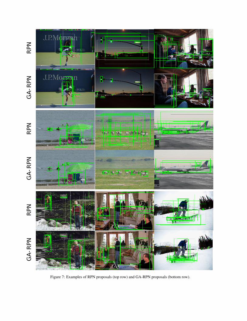
by 10.5% and AR1000 by 9.1% respectively. Notably, GA-RPN with a small backbone can achieve a much higher re-call than RPN with larger backbones. Our encouraging re-sults are supported by the qualitative results shown in Fig-ure 4, where we show the sparse and arbitrary shaped an-chors and visualize the outputs of two branches. It is ob-served that the anchors concentrate more on objects andprovides a good basis for the ensuing object proposal. InFigure 5, we show some examples of proposals generatedupon sliding window anchoring and guided anchoring.
Iterative regression and classification (“RPN+Iterative”and “RefineRPN”) only brings limited gain to RPN, whichproves the importance of the aforementioned rule of align-ment and consistency, and simply refining anchors multiple
Figure 5: Examples of RPN proposals (top row) and GA-RPN proposals (bottom row).
times is not effective enough. Keeping the center of anchorsfixed and adapt features based on anchor shapes are crucial.
To investigate the generalization ability of guided an-choring and its power to boost the detection performance,we integrate it into both two-stage and single-stage de-tection pipelines, including Fast R-CNN [11], Faster R-CNN [27] and RetinaNet [19]. For two-stage detectors,we replace the original RPN with GA-RPN, and for single-stage detectors, the sliding window anchoring scheme isreplaced with the proposed guided anchoring. Results inTable 2 show that guided anchoring not only increases theproposal recall of RPN, but also improves the detection per-formance by a large margin. With guided anchoring, themAP of these detectors are improved by 2.3%, 2.7% and1.2% respectively.
To further study the effectiveness of high-quality propos-als and investigate the fine-tuning scheme, we take a fullyconverged Faster R-CNN model and finetune it with pre-computed RPN or GA-RPN proposals. We finetune the de-tector for 3 epochs, with the learning rate of 0.02, 0.002and 0.0002 respectively. The results are in Table 3 illustratethat RPN proposals cannot bring any gain, while the high-quality GA-RPN proposals bring 2.2% mAP improvementto the trained model with only a time cost of 3 epochs.
4.3. Ablation Study
Model design. We omit different components in our designto investigate the effectiveness of each component, includ-ing location prediction, shape prediction and feature adap-tion. Results are shown in Table 4. The shape predictionbranch is shown effective which leads to a gain of 4.2%.
Table 4: The effects of each module in our design. L., S., andF.A. denote location, shape, and feature adaptation, respectively.
(b)Figure 6: (a) Anchor scale and (b) aspect ratio distributions ofdifferent anchoring schemes. The x-axis is reduced to log-spaceby apply log2(·) operator. GT, GA, SW indicates ground truth,guided anchoring, sliding window, respectively.
The location prediction branch brings marginal improve-ment. Nevertheless, the importance of this branch is re-flected in its usefulness of obtaining sparse anchors leadingto more efficient inference. The obvious gain brought by thefeature adaption module suggests the necessity of rearrang-ing the feature map according to predicted anchor shapes.This module helps to capture information corresponding toanchor scopes, especially for large objects.Anchor location. The location threshold εL controls thesparsity of anchor distribution. Adopting different thresh-olds will yield different numbers of anchors. To reveal theinfluence of εL on efficiency and performance, we vary thethreshold and compare the following results: the averagenumber of anchors per image, recall of final proposals andthe inference runtime. From Table 5 we can observe that theobjectness scores of most background regions are close to 0,so a small εL can greatly reduce the number of anchors bymore than 90%, with only a minor decrease on recall rate. Itis noteworthy that the head in RPN is just one convolutionallayer, so the speedup is not apparent. Nevertheless, a signif-icant reduction in the number of anchors offers a possibilityto perform more efficient inference with a heavier head.
Table 6: The effects of alignment and consistency rules. C.A. andF.A. denote center alignment (alignment rule) and feature adaption(consistency rule) respectively.
X 57.2 63.6 66.8 38.3 66.1 77.8X X 59.2 65.2 68.5 40.9 67.8 79.0
Anchor shape. We compare the set of generated anchorsof our method with sliding window anchors of pre-definedshapes. Since our method predicts only one anchor at eachlocation of the feature map instead of k (k = 3 in our base-line) anchors of different scales and aspect ratios, the totalanchor number is reduced by 1
k . We present the scale andaspect ratio distribution of our anchors with sliding windowanchors in Figure 6. The results show great advantages ofthe guided anchoring scheme over predefined anchor scalesand shapes. The predicted anchors cover a much widerrange of scales and aspect ratios, which have a similar dis-tribution to ground truth objects and provide a pool of initialanchors with higher coverage on objects.Feature adaption. The feature adaption module improvesthe recall by a large margin, proving that a remedy offeatures consistency is essential. We claim that the im-provement not only comes from adopting deformable con-volution, but also results from our design of using an-chor shape predictions to predict the offset of the de-formable convolution layer. If we simply add a deformableconvolution layer after anchor generation, the results ofAR100/AR300/AR1000 are 56.1%/62.4%/66.1%, whichare inferior to results from our design.Alignment and consistency rule. We verify the necessityof the two proposed rules. The alignment rule suggests thatwe should keep the anchor centers aligned with feature mappixels. According to the consistency rule, we design thefeature adaption module to refine the features. Results inTable 6 show the importance of these rules. 1) From row1 and 2, or row 3 and 4, we learn that predicting both theshape and center offset instead of just predicting the shapeharms the performance. 2) The comparison between row 1and 3, or row 2 and 4 shows the impact of consistency.The use of high-quality proposals. Despite with high-quality proposals, training a good detector remains a non-trivial problem. As illustrated in Figure 3, GA-RPN propos-als provide more candidates of high IoU. This suggests thatwe can use fewer proposals for training detectors. We testdifferent numbers of proposals and different IoU thresholdsto assign labels for foreground/background on Fast R-CNN.
From the results in Table 7, we observe that: (1) LargerIoU threshold is important for taking advantage of high-quality proposals. By focusing on positive samples of
Table 7: Exploration of utilizing high-quality proposals.
higher IoU, there will be fewer false positives and the fea-tures for classification are more discriminative. Since weassign negative labels to proposals with IoU less than 0.6during training, AP0.5 will decrease while AP of high IoUswill increase by a large margin, and the overall AP is muchhigher. (2) Using fewer proposals during training and test-ing can benefit the learning if the recall is high enough.Fewer proposals lead to a lower recall, but will simplifythe learning process, since there are more hard samplesin low-score proposals. When training with RPN propos-als, the performance will decrease if we use only 300 pro-posals, because the recall is not sufficient and many ob-jects get missed. However, GA-RPN guarantees high recalleven with fewer proposals, thus training with 300 proposalscould still boost the final mAP.Hyper-parameters. Our method is insensitive to hyper-parameters. (1) As we sample 3, 9, 15 pairs to approximateEq.(5), we respectively obtain AR@1000 68.3%, 68.5%,68.5%. (2) We set λ2 = 0.1 to balance the loss terms bydefault. We obtain 68.4% with λ2 = 0.2 or 0.05 and 68.3%with λ2 = 0.02. (3) We vary σ1 within [0.1, 0.5] and σ2within [0.2, 1.0], and the performance remains comparable(between 68.1% and 68.5%).
5. ConclusionWe have proposed the Guided Anchoring scheme, which
leverages semantic features to guide the anchoring. It gen-erates non-uniform anchors of arbitrary shapes by jointlypredicting the locations and anchor shapes dependent on lo-cations. The proposed method achieves 9.1% higher recallwith 90% fewer anchors than the RPN baseline using thesliding window scheme. It can also be applied to variousanchor-based detectors to improve the performance by asmuch as 2.7%.
Acknowledgment This work is partially supported bythe Collaborative Research grant from SenseTime Group(CUHK Agreement No. TS1610626 & No. TS1712093),the General Research Fund (GRF) of Hong Kong (No.14236516, No. 14203518 & No. 14224316), and Singa-pore MOE AcRF Tier 1 (M4012082.020).
RPN
GA
-RPN
RPN
GA
-RPN
RPN
GA
-RPN
RPN
GA
-RPN
RPN
GA
-RPN
Figure 7: Examples of RPN proposals (top row) and GA-RPN proposals (bottom row).
References[1] Zhaowei Cai and Nuno Vasconcelos. Cascade r-cnn: Delving
into high quality object detection. In IEEE Conference onComputer Vision and Pattern Recognition, 2018. 2
[3] Jifeng Dai, Yi Li, Kaiming He, and Jian Sun. R-fcn: Objectdetection via region-based fully convolutional networks. InAdvances in Neural Information Processing Systems, 2016.2
[4] Jifeng Dai, Yi Li, Kaiming He, and Jian Sun. R-FCN: Objectdetection via region-based fully convolutional networks. InAdvances in Neural Information Processing Systems, 2016.4
[5] Jia Deng, Wei Dong, Richard Socher, Li-Jia Li, Kai Li,and Li Fei-Fei. Imagenet: A large-scale hierarchical imagedatabase. In IEEE Conference on Computer Vision and Pat-tern Recognition, 2009. 1
[6] Mark Everingham, SM Ali Eslami, Luc Van Gool, Christo-pher KI Williams, John Winn, and Andrew Zisserman. Thepascal visual object classes challenge: A retrospective. Inter-national Journal of Computer Vision, 111(1):98–136, 2015.1
[7] Andreas Geiger, Philip Lenz, and Raquel Urtasun. Are weready for autonomous driving? the kitti vision benchmarksuite. In IEEE Conference on Computer Vision and PatternRecognition, 2012. 1
[8] Amir Ghodrati, Ali Diba, Marco Pedersoli, Tinne Tuyte-laars, and Luc Van Gool. Deepproposal: Hunting objects bycascading deep convolutional layers. In IEEE InternationalConference on Computer Vision, 2015. 2
[9] Spyros Gidaris and Nikos Komodakis. Object detectionvia a multi-region and semantic segmentation-aware cnnmodel. In IEEE International Conference on Computer Vi-sion, 2015. 2
[11] Ross Girshick. Fast r-cnn. In IEEE International Conferenceon Computer Vision, 2015. 7
[12] Kaiming He, Georgia Gkioxari, Piotr Dollar, and Ross Gir-shick. Mask r-cnn. In IEEE International Conference onComputer Vision, 2017. 2
[13] Kaiming He, Xiangyu Zhang, Shaoqing Ren, and Jian Sun.Deep residual learning for image recognition. In IEEE Con-ference on Computer Vision and Pattern Recognition, 2016.6
[14] Lichao Huang, Yi Yang, Yafeng Deng, and Yinan Yu. Dense-box: Unifying landmark localization with end to end objectdetection. arXiv preprint arXiv:1509.04874, 2015. 2, 4
[15] Zequn Jie, Xiaodan Liang, Jiashi Feng, Wen Feng Lu, EngHock Francis Tay, and Shuicheng Yan. Scale-aware pixel-wise object proposal networks. IEEE Transactions on ImageProcessing, 25(10):4525–4539, 2016. 2
[16] Hongyang Li, Yu Liu, Wanli Ouyang, and Xiaogang Wang.Zoom out-and-in network with map attention decision for re-gion proposal and object detection. International Journal ofComputer Vision, pages 1–14, 2017. 6
[17] Xiaoxiao Li, Ziwei Liu, Ping Luo, Chen Change Loy, andXiaoou Tang. Not all pixels are equal: difficulty-aware se-mantic segmentation via deep layer cascade. 2017. 3
[18] Tsung-Yi Lin, Piotr Dollar, Ross Girshick, Kaiming He,Bharath Hariharan, and Serge Belongie. Feature pyramidnetworks for object detection. In IEEE Conference on Com-puter Vision and Pattern Recognition, July 2017. 2, 3, 6
[19] Tsung-Yi Lin, Priya Goyal, Ross Girshick, Kaiming He, andPiotr Dollar. Focal loss for dense object detection. In IEEEInternational Conference on Computer Vision, 2017. 2, 3, 5,6, 7
[20] Tsung-Yi Lin, Michael Maire, Serge Belongie, James Hays,Pietro Perona, Deva Ramanan, Piotr Dollar, and C LawrenceZitnick. Microsoft coco: Common objects in context. InEuropean Conference on Computer Vision, 2014. 1, 5
[21] Wei Liu, Dragomir Anguelov, Dumitru Erhan, ChristianSzegedy, Scott Reed, Cheng-Yang Fu, and Alexander CBerg. Ssd: Single shot multibox detector. In European Con-ference on Computer Vision, 2016. 2
[22] Hsueh-Fu Lu, Xiaofei Du, and Ping-Lin Chang. Towardscale-invariance and position-sensitive region proposal net-works. European Conference on Computer Vision, 2018. 6
[23] Mahyar Najibi, Mohammad Rastegari, and Larry S Davis.G-cnn: an iterative grid based object detector. In IEEE Con-ference on Computer Vision and Pattern Recognition, pages2369–2377, 2016. 2
[24] Pedro O. Pinheiro, Tsung-Yi Lin, Ronan Collobert, and Pi-otr Dollr. Learning to refine object segments. In EuropeanConference on Computer Vision, 2016. 6
[25] Joseph Redmon, Santosh Divvala, Ross Girshick, and AliFarhadi. You only look once: Unified, real-time object de-tection. In IEEE Conference on Computer Vision and PatternRecognition, 2016. 2
[26] Joseph Redmon and Ali Farhadi. Yolo9000: Better, faster,stronger. In IEEE Conference on Computer Vision and Pat-tern Recognition, 2017. 2
[27] Shaoqing Ren, Kaiming He, Ross Girshick, and Jian Sun.Faster r-cnn: Towards real-time object detection with regionproposal networks. In Advances in Neural Information Pro-cessing Systems, 2015. 1, 2, 4, 5, 7