24
RegulatoR®, Keyless Locking 1 Instruction Manual

RegulatoR®, Keyless Locking 24
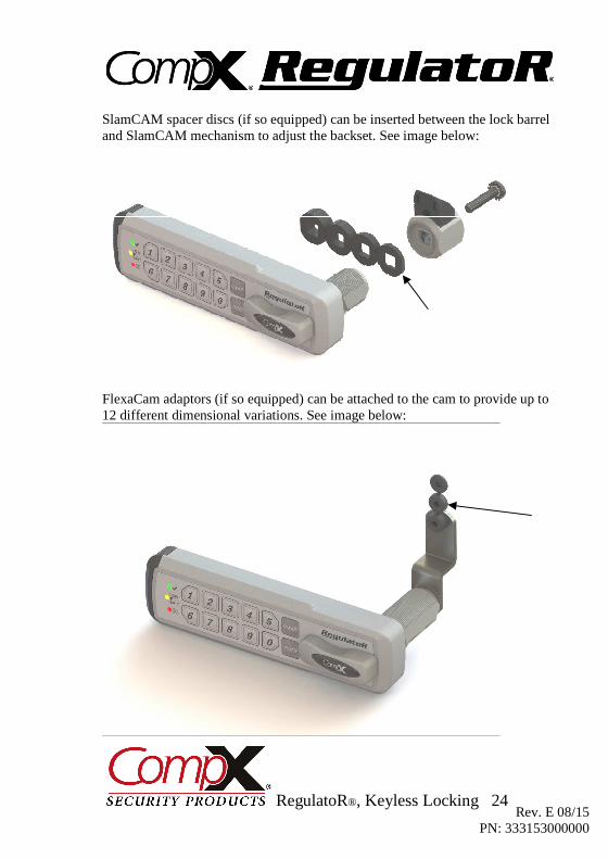
SlamCAM spacer discs (if so equipped) can be inserted between the lock barrel and SlamCAM mechanism to adjust the backset. See image below:
FlexaCam adaptors (if so equipped) can be attached to the cam to provide up to 12 different dimensional variations. See image below:
Rev. E 08/15 PN: 333153000000
RegulatoR®, Keyless Locking 1
Instruction Manual

RegulatoR®, Keyless Locking 2
Thank you for purchasing the CompX® RegulatoR®. The RegulatoR is an innovative solution for locking cabinet doors and drawers. It can mount to cabinet doors or drawers with a material thickness of 1/32” to 1-7/16”. Powered by 2-AAA batteries (included), RegulatoR operates using a 4 to 8 digit code. Operation is simple: type a valid code and press ENTER. Then just turn the lever to the locked or unlocked position. RegulatoR is easy to install, and offers: Programmable user and supervisor codes Programmable modes of operation Programmable reset features RegulatoR is intended for interior use only. Operating Temperature: 50°F – 120°F (10°C – 48°C) Note: It is strongly recommended that batteries be replaced on an annual basis. In the event the batteries should die, they can be replaced via the external battery compartment.
RegulatoR®, Keyless Locking 23
RegulatoR Part Number Descriptions Example: REG-S-L-3-BK REG = RegulatoR Standard Knob REGS = RegulatoR Short Knob Version: S = Self-locking; featuring SlamCAM M = Manual locking, standard CompX National cams Mounting: L = Left hand mount, door application - hinge on left side when facing cabinet R = Right hand mount door application - hinge on right side when facing cabinet V = Vertical mount door application (keypad located above locking point) T = Top vertical mount door application (keypad located below locking point) Cylinder Length: 1 = 7/16" cylinder length 3 = 1-3/16" cylinder length 5 = 1-3/4" cylinder length Color: BK = Matte black housing & knob No suffix = Standard silver housing & knob ------------------------------------------------------------------------------------------------- Replacement Parts REG-KIT-KNOB - replacement knob kit REG-KIT-KNOBS - replacement short knob kit 213005000000J - replacement battery door

RegulatoR®, Keyless Locking 22
RegulatoR®, Keyless Locking 3
Packaged Components CompX® RegulatoR® is offered in two versions: Manual Lock and Self Lock. Contents will vary depending on the version. Contents – Manual Lock Version:
Manual RegulatoR Lock Assembly 2 AAA alkaline batteries 1 Offset locking cam / 1 Straight locking cam FlexaCam adapters Mounting hardware
Contents – Self Lock Version:
Self Locking RegulatoR Lock assembly featuring SlamCAM 2 AAA alkaline batteries SlamCAM spacer discs Mounting hardware
Each lock contains 2 green stickers that are needed for resetting RegulatoR. In the event RegulatoR needs to be reset, one green sticker is placed on the back of the device. The remaining green sticker should be saved in a safe and secure location for future reference. (See page 11 for reset instructions.) Care and Cleaning To clean the RegulatoR surface, apply non-acid based cleaner to a clean cotton cloth; do not spray cleaner directly on the RegulatoR. Wipe down keypad and its respective housing surfaces of excess cleaner.

RegulatoR®, Keyless Locking 4
Table of Contents Powering Up and Battery Installation ………………………………………….5 Programming Introduction ……………………………………………………..6 Programming Mode …………………………………………………………….9 Changing the User Code ……………………………………………………….10 Changing the Supervisor Code ………………………………………………...11 Single Use/Standard Mode …………………………………………………….12 Single Use Timeout ON/OFF ………………………………………………….13 Security Timeout ON/OFF …………………………………………………….14 Reset User Code ……………………………………………………………….15 Technician Mode ……………………………………………………………....16 User Slot (03-20) Programming ……………………………………………….18 Mounting Template ……………………………………………………………22 Part Number Descriptions ……………………………………………………..23
RegulatoR®, Keyless Locking 21
Delete User From Specific Memory Slot (03 – 20) The Supervisor code memory location is called Slot 01 and the first User code is called Slot 02.
– The additional user codes reside in memory slots 03-20. – To delete a user code from a specific memory slot (03 -20), follow the
steps on page 9 to enter programming mode. There is a 10 second programming time limit between each step. If RegulatoR times out or an error is made, programming will end and you will need to enter programming mode again.
1. Place RegulatoR into programming mode (see page 9). 2. Press 401 and then press ENTER. 3. Type memory slot to be vacated followed by ENTER (for memory
slots 03 - 09, you must type leading “0” – e.g. “07” for slot 7) 4. Retype memory slot to be vacated followed by ENTER. 5. If successful, the yellow indicator light will illuminate.
Continue programming or press 9 and then ENTER to exit programming.

RegulatoR®, Keyless Locking 20
Delete User Without Specifying Memory Slot The Supervisor code memory location is called Slot 01 and the first User code is called Slot 02.
– The additional user codes reside in memory slots 03-20. – To delete a user code without specifying a memory slot (03 -20), follow
the steps on page 9 to enter programming mode. There is a 10 second programming time limit between each step. If RegulatoR times out or an error is made, programming will end and you will need to enter programming mode again.
1. Place RegulatoR into programming mode (see page 9). 2. Press 400 and then press ENTER. 3. Type the user code to be deleted and press ENTER. 4. Retype the user code to be deleted and press ENTER. 5. If successful, the yellow indicator light will illuminate.
Continue programming or press 9 and then ENTER to exit programming.
RegulatoR®, Keyless Locking 5
Powering Up and Battery Installation CompX® RegulatoR® is shipped with two AAA batteries. While RegulatoR features a low battery indicator, annual battery replacement is recommended. Mixing batteries of different chemistries could damage the RegulatoR resulting in lock failure. To power up RegulatoR, remove the red tag. Lock is now ready for use. A T-15 pin in head Torx® (6-lobe) will be required to remove the battery cover. (Not Included) To change batteries: 1. Loosen the retaining screw. 2. Remove battery cover. 3. Press CLEAR 5 times. 4. Insert new batteries as shown in the illustration. 5. Reinstall battery cover, tighten retaining screw.

RegulatoR®, Keyless Locking 6
Programming – Introduction CompX® RegulatoR® is easy to program and operate. Type the user code (factory default 1234) and press ENTER to lock or unlock the cabinet. The supervisor can change operating codes, modes and restore lock settings. While RegulatoR is easy to program, we highly recommend reading the complete programming instructions prior to making any changes. Remember to keep track of any programming changes. Button locations, indicator lights and knob referenced in the programming instructions are shown below. CLEAR button erases any key input made in error Indicator Lights
Green – Indicates button input and valid code Yellow - Indicates low battery or program mode. Red – Indicates incorrect entry
Knob is always rotated clockwise to unlock ENTER button is used to complete code and counter clockwise to lock and begin programming
RegulatoR®, Keyless Locking 19
Add User to Specific Memory Slot (03 – 20) The Supervisor code memory location is called Slot 01 and the first User code is called Slot 02.
– Any additional user codes reside in memory slots 03-20. – To add a user code to a specific memory slot (03 -20), follow the steps
on page 9 to enter programming mode. User codes must be 4 to 8 digits in length and must be different from all existing codes (including Slot 01 Supervisor & Slot 02 User codes). There is a 10 second programming time limit between each step. If RegulatoR times out or an error is made, programming will end and you will need to enter programming mode again.
1. Place RegulatoR into programming mode (see page 9). 2. Press 411 and then press ENTER. 3. Type memory slot to be added followed by ENTER (for memory slots
03 - 09, you must type leading “0” – e.g. “07” for slot 7) 4. Retype memory slot to be added followed by ENTER 5. Type the new user code and press ENTER. 6. Retype the new user code and press ENTER. 7. If successful, the yellow indicator light will illuminate.
Continue programming or press 9 and then ENTER to exit programming.
RegulatoR®, Keyless Locking 18
Add User Without Specifying Memory Slot The Supervisor Code memory location is called Slot 01 and the first User Code is called Slot 02.
– Any additional User Codes reside in memory slots 03-20. – To add a user code without specifying a memory slot (03 -20), follow
the steps on page 9 to enter programming mode. User codes must be 4 to 8 digits in length and must be different from all existing codes (including Slot 01 Supervisor & Slot 02 User codes). There is a 10 second programming time limit between each step. If RegulatoR times out or an error is made, programming will end and you will need to enter programming mode again.
1. Place RegulatoR into programming mode (see page 9). 2. Press 410 and then press ENTER. 3. Type the new user code and press ENTER. 4. Retype the new user code and press ENTER. 5. If successful, the yellow indicator light will illuminate.
Continue programming or press 9 and then ENTER to exit programming.
RegulatoR®, Keyless Locking 7
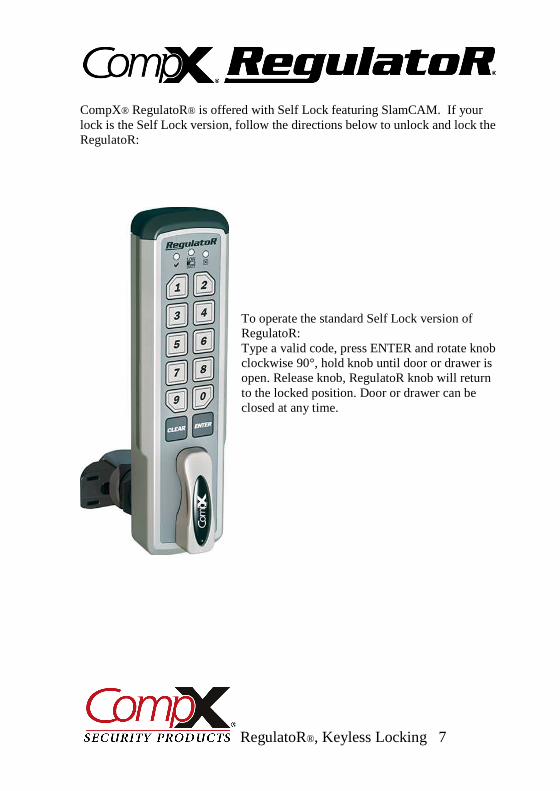
CompX® RegulatoR® is offered with Self Lock featuring SlamCAM. If your lock is the Self Lock version, follow the directions below to unlock and lock the RegulatoR:
To operate the standard Self Lock version of RegulatoR: Type a valid code, press ENTER and rotate knob clockwise 90°, hold knob until door or drawer is open. Release knob, RegulatoR knob will return to the locked position. Door or drawer can be closed at any time.

RegulatoR®, Keyless Locking 8
CompX® RegulatoR® is offered in a Manual Lock version. If your lock is the Manual Lock version follow the directions below to unlock and lock the RegulatoR.
To operate the standard Manual Lock version of RegulatoR: To unlock, type a valid code, press ENTER and rotate knob clockwise 90°. To lock, rotate knob 90° counter clockwise.
RegulatoR®, Keyless Locking 17
Technician Mode - Operation TO UNLOCK
1. Type the Technician Code and press ENTER. 2. Turn the knob clockwise 90° to the unlocked position (all three LED
lights will have a rotating blinking pattern). 3. To relock & retain the single use code that already exists; rotate the
knob 90° counter clockwise. OR
To remove the existing single use code and leave the RegulatoR unlocked: Type the Technician Code and press ENTER. Press 1 then press & hold CLEAR for 3 seconds.

RegulatoR®, Keyless Locking 16
Technician Mode – Programming (Manual locking RegulatoR only) When Technician Mode is ON, the programmed Technician Code can be used to unlock a locked Single Use Mode RegulatoR without erasing the existing single use code. There is a 10 second programming time limit between each step. If RegulatoR times out or error is made, programming will end and you will need to enter programming mode again.
1. Place RegulatoR into programming mode (see page 9). 2. To turn Technician Mode ON: type 31 and then press ENTER. 3. Type the desired 4 to 8 digit Technician Code and then press ENTER. 4. Retype Technician Code and then press ENTER 5. REMEMBER THIS CODE
OR To turn Technician Mode OFF: type 30 and then press ENTER
– If successful, the green indicator light will illuminate for 1 second.
– Press 9 followed by ENTER to exit Programming Mode
RegulatoR®, Keyless Locking 9
RegulatoR Programming Mode To enter programming mode you must know the supervisor code. The default supervisor code is 12345. Once in programming mode, multiple changes can be made prior to exiting programming. There is a 10 second programming time limit between each step. If RegulatoR times out or an error is made, programming will end and you will need to enter programming mode again.
1. Lock must be in the locked position prior to entering programming mode.
2. Type supervisor code and press ENTER. Rotate the knob to the unlocked position and press and hold ENTER for 3 seconds (yellow indicator light will illuminate).
• If product is Self Lock with the SlamCAM feature you can now let go of the knob.
3. With the yellow indicator light illuminated, programming can begin.

RegulatoR®, Keyless Locking 10
Changing the User Code To change the user code, follow the steps on page 9 to enter programming mode. The factory default user code is 1234 (User codes must be 4 to 8 digits in length.) There is a 10 second programming time limit between each step. If RegulatoR times out or an error is made, programming will end and you will need to enter programming mode again.
1. Place RegulatoR into programming mode (see page 9). 2. Press 1 and then press ENTER. 3. Type the current user code and press ENTER. 4. Type the new user code and press ENTER. 5. Retype the new user code and press ENTER. 6. If successful, the green indicator light will illuminate for 1 second.
Continue programming or press 9 and then ENTER to exit programming.
RegulatoR®, Keyless Locking 15
Reset User Code to Factory Default 1234 (Does not apply to Single Use Mode) To reset the User Code to the factory default 1234 follow the steps on page 9 to enter programming mode. There is a 10 second programming time limit between each step. If RegulatoR times out or error is made, programming will end and you will need to enter programming mode again.
1. Place RegulatoR into programming mode (see page 9). 2. Type 8888 and then press the ENTER button. 3. If successful, the green indicator light will illuminate for 1 second.
Continue programming or press 9 and then ENTER to exit programming.

RegulatoR®, Keyless Locking 14
Programming Security Timeout ON / Security Timeout OFF Warning: Security Timeout ON will disable the RegulatoR from use for 5 minutes when 5 invalid attempts to unlock RegulatoR occur. During this time, RegulatoR will not unlock with either the valid user or supervisor code. To change the RegulatoR to Security Timeout ON or OFF, follow the steps on page 9 to enter programming mode. There is a 10 second programming time limit between each step. If RegulatoR times out or error is made, programming will end and you will need to enter programming mode again.
1. Place RegulatoR into programming mode see page 9).
a. To turn Security Timeout ON, type 11 and then press ENTER.
OR b. To turn Security Timeout OFF, type 10 and then press
ENTER.
2. If successful, the green indicator light will illuminate for 1 second. Continue programming or press 9 and then ENTER to exit programming.
RegulatoR®, Keyless Locking 11
Changing the Supervisor Code To change the supervisor code, follow the steps on page 9 to enter programming mode. The factory default supervisor code is 12345 (supervisor codes must be 4 to 8 digits in length.) There is a 10 second programming time limit between each step. If RegulatoR times out or an error is made, programming will end and you will need to enter programming mode again.
1. Place RegulatoR into programming mode (see page 9). 2. Press 2 and then press ENTER. 3. Type the current supervisor code and press ENTER. 4. Type the new supervisor code and press ENTER. 5. Retype the new supervisor code and press ENTER. 6. If successful, the green indicator light will illuminate for 1 second.
Continue programming or press 9 and then ENTER to exit programming. RegulatoR® features a reset code which will restore the default supervisor code and user code. RegulatoR was shipped with reset stickers; one attached to the back of the RegulatoR and an extra sticker that should be saved in a safe and secure location for future reference. To restore the factory default supervisor and user code, type the Reset Code assigned to the RegulatoR and press ENTER. CompX® RegulatoR® features several modes of operation. These functions can be changed using the following instructions with a valid supervisor code.

RegulatoR®, Keyless Locking 12
Programming Single Use Mode / Standard Mode Single Use Mode allows for a revolving user code so multiple people may use the lock without having to reprogram the RegulatoR each time. Note: This mode cannot be used with Self Lock with SlamCAM. Standard Mode RegulatoR operates with a fixed code. To change the code, follow the Changing the User Code steps on page 10. To change the RegulatoR to Single Use or Standard Mode, follow the steps on page 9 to enter programming mode. There is a 10 second programming time limit between each step. If RegulatoR times out or an error is made, programming will end and you will need to enter programming mode again.
1. Place RegulatoR into programming mode (see page 9).
a. To turn Single Use Mode “ON”: type 51 and then press ENTER.
OR b. To return to Standard Mode: type 50 and then press ENTER.
2. If successful, the green indicator light will illuminate for 1 second. Note: Returning to Standard Mode will reset the factory user default code (1234). Continue programming or press 9 and then ENTER to exit programming.
RegulatoR®, Keyless Locking 13
Programming Single Use Timeout ON / Single Use Timeout OFF Warning: Manual Lock - Single Use Timeout ON is a feature to prevent users from occupying a shared use locker or cabinet for a prolonged period of time. Turning this feature on will disable the user code after a programmable amount of time. After this time elapses, RegulatoR and can only be opened with the supervisor code. To change the RegulatoR to Single Use Timeout ON or OFF, follow the steps on page 9 to enter programming mode. There is a 10 second programming time limit between each step. If RegulatoR times out or an error is made, programming will end and you will need to enter programming mode again.
1. Place RegulatoR into programming mode (see page 9).
a. To set Timeout ON, type 2XX and then press ENTER. (XX represents a time period from 04 - 12 in whole hours.)
OR b. To turn Timeout OFF, type 20 and then press ENTER.
3. If successful, the green indicator light will illuminate for 1 second. Continue programming or press 9 and then ENTER to exit programming.

RegulatoR®, Keyless Locking 14
Programming Security Timeout ON / Security Timeout OFF Warning: Security Timeout ON will disable the RegulatoR from use for 5 minutes when 5 invalid attempts to unlock RegulatoR occur. During this time, RegulatoR will not unlock with either the valid user or supervisor code. To change the RegulatoR to Security Timeout ON or OFF, follow the steps on page 9 to enter programming mode. There is a 10 second programming time limit between each step. If RegulatoR times out or error is made, programming will end and you will need to enter programming mode again.
1. Place RegulatoR into programming mode see page 9).
a. To turn Security Timeout ON, type 11 and then press ENTER.
OR b. To turn Security Timeout OFF, type 10 and then press
ENTER.
2. If successful, the green indicator light will illuminate for 1 second. Continue programming or press 9 and then ENTER to exit programming.
RegulatoR®, Keyless Locking 11
Changing the Supervisor Code To change the supervisor code, follow the steps on page 9 to enter programming mode. The factory default supervisor code is 12345 (supervisor codes must be 4 to 8 digits in length.) There is a 10 second programming time limit between each step. If RegulatoR times out or an error is made, programming will end and you will need to enter programming mode again.
1. Place RegulatoR into programming mode (see page 9). 2. Press 2 and then press ENTER. 3. Type the current supervisor code and press ENTER. 4. Type the new supervisor code and press ENTER. 5. Retype the new supervisor code and press ENTER. 6. If successful, the green indicator light will illuminate for 1 second.
Continue programming or press 9 and then ENTER to exit programming. RegulatoR® features a reset code which will restore the default supervisor code and user code. RegulatoR was shipped with reset stickers; one attached to the back of the RegulatoR and an extra sticker that should be saved in a safe and secure location for future reference. To restore the factory default supervisor and user code, type the Reset Code assigned to the RegulatoR and press ENTER. CompX® RegulatoR® features several modes of operation. These functions can be changed using the following instructions with a valid supervisor code.

RegulatoR®, Keyless Locking 10
Changing the User Code To change the user code, follow the steps on page 9 to enter programming mode. The factory default user code is 1234 (User codes must be 4 to 8 digits in length.) There is a 10 second programming time limit between each step. If RegulatoR times out or an error is made, programming will end and you will need to enter programming mode again.
1. Place RegulatoR into programming mode (see page 9). 2. Press 1 and then press ENTER. 3. Type the current user code and press ENTER. 4. Type the new user code and press ENTER. 5. Retype the new user code and press ENTER. 6. If successful, the green indicator light will illuminate for 1 second.
Continue programming or press 9 and then ENTER to exit programming.
RegulatoR®, Keyless Locking 15
Reset User Code to Factory Default 1234 (Does not apply to Single Use Mode) To reset the User Code to the factory default 1234 follow the steps on page 9 to enter programming mode. There is a 10 second programming time limit between each step. If RegulatoR times out or error is made, programming will end and you will need to enter programming mode again.
1. Place RegulatoR into programming mode (see page 9). 2. Type 8888 and then press the ENTER button. 3. If successful, the green indicator light will illuminate for 1 second.
Continue programming or press 9 and then ENTER to exit programming.

RegulatoR®, Keyless Locking 16
Technician Mode – Programming (Manual locking RegulatoR only) When Technician Mode is ON, the programmed Technician Code can be used to unlock a locked Single Use Mode RegulatoR without erasing the existing single use code. There is a 10 second programming time limit between each step. If RegulatoR times out or error is made, programming will end and you will need to enter programming mode again.
1. Place RegulatoR into programming mode (see page 9). 2. To turn Technician Mode ON: type 31 and then press ENTER. 3. Type the desired 4 to 8 digit Technician Code and then press ENTER. 4. Retype Technician Code and then press ENTER 5. REMEMBER THIS CODE
OR To turn Technician Mode OFF: type 30 and then press ENTER
– If successful, the green indicator light will illuminate for 1 second.
– Press 9 followed by ENTER to exit Programming Mode
RegulatoR®, Keyless Locking 9
RegulatoR Programming Mode To enter programming mode you must know the supervisor code. The default supervisor code is 12345. Once in programming mode, multiple changes can be made prior to exiting programming. There is a 10 second programming time limit between each step. If RegulatoR times out or an error is made, programming will end and you will need to enter programming mode again.
1. Lock must be in the locked position prior to entering programming mode.
2. Type supervisor code and press ENTER. Rotate the knob to the unlocked position and press and hold ENTER for 3 seconds (yellow indicator light will illuminate).
• If product is Self Lock with the SlamCAM feature you can now let go of the knob.
3. With the yellow indicator light illuminated, programming can begin.
RegulatoR®, Keyless Locking 8
CompX® RegulatoR® is offered in a Manual Lock version. If your lock is the Manual Lock version follow the directions below to unlock and lock the RegulatoR.
To operate the standard Manual Lock version of RegulatoR: To unlock, type a valid code, press ENTER and rotate knob clockwise 90°. To lock, rotate knob 90° counter clockwise.
RegulatoR®, Keyless Locking 17
Technician Mode - Operation TO UNLOCK
1. Type the Technician Code and press ENTER. 2. Turn the knob clockwise 90° to the unlocked position (all three LED
lights will have a rotating blinking pattern). 3. To relock & retain the single use code that already exists; rotate the
knob 90° counter clockwise. OR
To remove the existing single use code and leave the RegulatoR unlocked: Type the Technician Code and press ENTER. Press 1 then press & hold CLEAR for 3 seconds.

RegulatoR®, Keyless Locking 18
Add User Without Specifying Memory Slot The Supervisor Code memory location is called Slot 01 and the first User Code is called Slot 02.
– Any additional User Codes reside in memory slots 03-20. – To add a user code without specifying a memory slot (03 -20), follow
the steps on page 9 to enter programming mode. User codes must be 4 to 8 digits in length and must be different from all existing codes (including Slot 01 Supervisor & Slot 02 User codes). There is a 10 second programming time limit between each step. If RegulatoR times out or an error is made, programming will end and you will need to enter programming mode again.
1. Place RegulatoR into programming mode (see page 9). 2. Press 410 and then press ENTER. 3. Type the new user code and press ENTER. 4. Retype the new user code and press ENTER. 5. If successful, the yellow indicator light will illuminate.
Continue programming or press 9 and then ENTER to exit programming.
RegulatoR®, Keyless Locking 7
CompX® RegulatoR® is offered with Self Lock featuring SlamCAM. If your lock is the Self Lock version, follow the directions below to unlock and lock the RegulatoR:
To operate the standard Self Lock version of RegulatoR: Type a valid code, press ENTER and rotate knob clockwise 90°, hold knob until door or drawer is open. Release knob, RegulatoR knob will return to the locked position. Door or drawer can be closed at any time.

RegulatoR®, Keyless Locking 6
Programming – Introduction CompX® RegulatoR® is easy to program and operate. Type the user code (factory default 1234) and press ENTER to lock or unlock the cabinet. The supervisor can change operating codes, modes and restore lock settings. While RegulatoR is easy to program, we highly recommend reading the complete programming instructions prior to making any changes. Remember to keep track of any programming changes. Button locations, indicator lights and knob referenced in the programming instructions are shown below. CLEAR button erases any key input made in error Indicator Lights
Green – Indicates button input and valid code Yellow - Indicates low battery or program mode. Red – Indicates incorrect entry
Knob is always rotated clockwise to unlock ENTER button is used to complete code and counter clockwise to lock and begin programming
RegulatoR®, Keyless Locking 19
Add User to Specific Memory Slot (03 – 20) The Supervisor code memory location is called Slot 01 and the first User code is called Slot 02.
– Any additional user codes reside in memory slots 03-20. – To add a user code to a specific memory slot (03 -20), follow the steps
on page 9 to enter programming mode. User codes must be 4 to 8 digits in length and must be different from all existing codes (including Slot 01 Supervisor & Slot 02 User codes). There is a 10 second programming time limit between each step. If RegulatoR times out or an error is made, programming will end and you will need to enter programming mode again.
1. Place RegulatoR into programming mode (see page 9). 2. Press 411 and then press ENTER. 3. Type memory slot to be added followed by ENTER (for memory slots
03 - 09, you must type leading “0” – e.g. “07” for slot 7) 4. Retype memory slot to be added followed by ENTER 5. Type the new user code and press ENTER. 6. Retype the new user code and press ENTER. 7. If successful, the yellow indicator light will illuminate.
Continue programming or press 9 and then ENTER to exit programming.
RegulatoR®, Keyless Locking 20
Delete User Without Specifying Memory Slot The Supervisor code memory location is called Slot 01 and the first User code is called Slot 02.
– The additional user codes reside in memory slots 03-20. – To delete a user code without specifying a memory slot (03 -20), follow
the steps on page 9 to enter programming mode. There is a 10 second programming time limit between each step. If RegulatoR times out or an error is made, programming will end and you will need to enter programming mode again.
1. Place RegulatoR into programming mode (see page 9). 2. Press 400 and then press ENTER. 3. Type the user code to be deleted and press ENTER. 4. Retype the user code to be deleted and press ENTER. 5. If successful, the yellow indicator light will illuminate.
Continue programming or press 9 and then ENTER to exit programming.
RegulatoR®, Keyless Locking 5
Powering Up and Battery Installation CompX® RegulatoR® is shipped with two AAA batteries. While RegulatoR features a low battery indicator, annual battery replacement is recommended. Mixing batteries of different chemistries could damage the RegulatoR resulting in lock failure. To power up RegulatoR, remove the red tag. Lock is now ready for use. A T-15 pin in head Torx® (6-lobe) will be required to remove the battery cover. (Not Included) To change batteries: 1. Loosen the retaining screw. 2. Remove battery cover. 3. Press CLEAR 5 times. 4. Insert new batteries as shown in the illustration. 5. Reinstall battery cover, tighten retaining screw.

RegulatoR®, Keyless Locking 4
Table of Contents Powering Up and Battery Installation ………………………………………….5 Programming Introduction ……………………………………………………..6 Programming Mode …………………………………………………………….9 Changing the User Code ……………………………………………………….10 Changing the Supervisor Code ………………………………………………...11 Single Use/Standard Mode …………………………………………………….12 Single Use Timeout ON/OFF ………………………………………………….13 Security Timeout ON/OFF …………………………………………………….14 Reset User Code ……………………………………………………………….15 Technician Mode ……………………………………………………………....16 User Slot (03-20) Programming ……………………………………………….18 Mounting Template ……………………………………………………………22 Part Number Descriptions ……………………………………………………..23
RegulatoR®, Keyless Locking 21
Delete User From Specific Memory Slot (03 – 20) The Supervisor code memory location is called Slot 01 and the first User code is called Slot 02.
– The additional user codes reside in memory slots 03-20. – To delete a user code from a specific memory slot (03 -20), follow the
steps on page 9 to enter programming mode. There is a 10 second programming time limit between each step. If RegulatoR times out or an error is made, programming will end and you will need to enter programming mode again.
1. Place RegulatoR into programming mode (see page 9). 2. Press 401 and then press ENTER. 3. Type memory slot to be vacated followed by ENTER (for memory
slots 03 - 09, you must type leading “0” – e.g. “07” for slot 7) 4. Retype memory slot to be vacated followed by ENTER. 5. If successful, the yellow indicator light will illuminate.
Continue programming or press 9 and then ENTER to exit programming.

RegulatoR®, Keyless Locking 22
RegulatoR®, Keyless Locking 3
Packaged Components CompX® RegulatoR® is offered in two versions: Manual Lock and Self Lock. Contents will vary depending on the version. Contents – Manual Lock Version:
Manual RegulatoR Lock Assembly 2 AAA alkaline batteries 1 Offset locking cam / 1 Straight locking cam FlexaCam adapters Mounting hardware
Contents – Self Lock Version:
Self Locking RegulatoR Lock assembly featuring SlamCAM 2 AAA alkaline batteries SlamCAM spacer discs Mounting hardware
Each lock contains 2 green stickers that are needed for resetting RegulatoR. In the event RegulatoR needs to be reset, one green sticker is placed on the back of the device. The remaining green sticker should be saved in a safe and secure location for future reference. (See page 11 for reset instructions.) Care and Cleaning To clean the RegulatoR surface, apply non-acid based cleaner to a clean cotton cloth; do not spray cleaner directly on the RegulatoR. Wipe down keypad and its respective housing surfaces of excess cleaner.

RegulatoR®, Keyless Locking 2
Thank you for purchasing the CompX® RegulatoR®. The RegulatoR is an innovative solution for locking cabinet doors and drawers. It can mount to cabinet doors or drawers with a material thickness of 1/32” to 1-7/16”. Powered by 2-AAA batteries (included), RegulatoR operates using a 4 to 8 digit code. Operation is simple: type a valid code and press ENTER. Then just turn the lever to the locked or unlocked position. RegulatoR is easy to install, and offers: Programmable user and supervisor codes Programmable modes of operation Programmable reset features RegulatoR is intended for interior use only. Operating Temperature: 50°F – 120°F (10°C – 48°C) Note: It is strongly recommended that batteries be replaced on an annual basis. In the event the batteries should die, they can be replaced via the external battery compartment.
RegulatoR®, Keyless Locking 23
RegulatoR Part Number Descriptions Example: REG-S-L-3-BK REG = RegulatoR Standard Knob REGS = RegulatoR Short Knob Version: S = Self-locking; featuring SlamCAM M = Manual locking, standard CompX National cams Mounting: L = Left hand mount, door application - hinge on left side when facing cabinet R = Right hand mount door application - hinge on right side when facing cabinet V = Vertical mount door application (keypad located above locking point) T = Top vertical mount door application (keypad located below locking point) Cylinder Length: 1 = 7/16" cylinder length 3 = 1-3/16" cylinder length 5 = 1-3/4" cylinder length Color: BK = Matte black housing & knob No suffix = Standard silver housing & knob ------------------------------------------------------------------------------------------------- Replacement Parts REG-KIT-KNOB - replacement knob kit REG-KIT-KNOBS - replacement short knob kit 213005000000J - replacement battery door
RegulatoR®, Keyless Locking 24
SlamCAM spacer discs (if so equipped) can be inserted between the lock barrel and SlamCAM mechanism to adjust the backset. See image below:
FlexaCam adaptors (if so equipped) can be attached to the cam to provide up to 12 different dimensional variations. See image below:
Rev. E 08/15 PN: 333153000000
RegulatoR®, Keyless Locking 1
Instruction Manual


