40
Construction Automotive Industry www.rehau.com REHAU RADIANT HEATING SYSTEMS INSTALLATION GUIDE

Construction
Automotive
Industry
www.rehau.com
REHAU RADIANT HEATING SYSTEMSINSTALLATION GUIDE

2
Table of Contents
1. Scope . . . . . . . . . . . . . . . . . . . . . . . . . . . . . . . . . . . . . . . . . . . . . . . . . . . 3
2. Installation Considerations. . . . . . . . . . . . . . . . . . . . . . . . . . . . . . . . . . . 4
3. Installation Overview . . . . . . . . . . . . . . . . . . . . . . . . . . . . . . . . . . . . . . . 5
4. System Component Overview . . . . . . . . . . . . . . . . . . . . . . . . . . . . . . . . 6
5. Preparing for Installation . . . . . . . . . . . . . . . . . . . . . . . . . . . . . . . . . . . . 7
6. Installing Manifolds . . . . . . . . . . . . . . . . . . . . . . . . . . . . . . . . . . . . . . . 11
7. Connecting Pipes to Manifolds . . . . . . . . . . . . . . . . . . . . . . . . . . . . . . . 13
8. Handling Pipe . . . . . . . . . . . . . . . . . . . . . . . . . . . . . . . . . . . . . . . . . . . . 14
9. Installing Pipe in Floor, Wall or Ceiling . . . . . . . . . . . . . . . . . . . . . . . . . 18
10. Testing the System. . . . . . . . . . . . . . . . . . . . . . . . . . . . . . . . . . . . . . . . 26
11. Pouring Slab or Overpour . . . . . . . . . . . . . . . . . . . . . . . . . . . . . . . . . . . 28
12. Completing the Finished Covering . . . . . . . . . . . . . . . . . . . . . . . . . . . . 30
13. Starting the System . . . . . . . . . . . . . . . . . . . . . . . . . . . . . . . . . . . . . . . 33
This symbol and the signal words DANGER, WARNING or CAUTION alert you
to personal injury hazards. If you don’t avoid the hazardous situation:
– DANGER! Will result in death or serious injury
– WARNING! Could result in death or serious injury
– CAUTION! Can result in minor or moderate injury
The signal word NOTICE is used to help you avoid property damage. We
cannot warn of all hazards; you must also use your own good judgment.
For updates to this publication and the most current REHAU technical guidelines,
safety information and manufacturer's recommendations, visit
na.rehau.com/resourcecenter
3
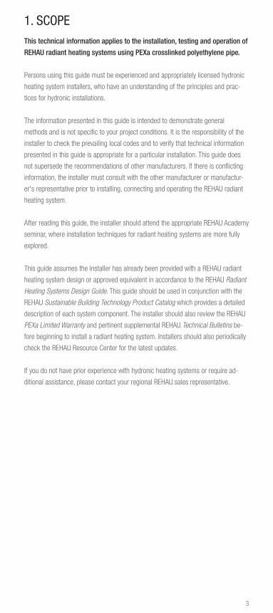
1. SCOPEThis technical information applies to the installation, testing and operation of
REHAU radiant heating systems using PEXa crosslinked polyethylene pipe.
Persons using this guide must be experienced and appropriately licensed hydronic
heating system installers, who have an understanding of the principles and prac-
tices for hydronic installations.
The information presented in this guide is intended to demonstrate general
methods and is not specific to your project conditions. It is the responsibility of the
installer to check the prevailing local codes and to verify that technical information
presented in this guide is appropriate for a particular installation. This guide does
not supersede the recommendations of other manufacturers. If there is conflicting
information, the installer must consult with the other manufacturer or manufactur-
er's representative prior to installing, connecting and operating the REHAU radiant
heating system.
After reading this guide, the installer should attend the appropriate REHAU Academy
seminar, where installation techniques for radiant heating systems are more fully
explored.
This guide assumes the installer has already been provided with a REHAU radiant
heating system design or approved equivalent in accordance to the REHAU Radiant
Heating Systems Design Guide. This guide should be used in conjunction with the
REHAU Sustainable Building Technology Product Catalog which provides a detailed
description of each system component. The installer should also review the REHAU
PEXa Limited Warranty and pertinent supplemental REHAU Technical Bulletins be-
fore beginning to install a radiant heating system. Installers should also periodically
check the REHAU Resource Center for the latest updates.
If you do not have prior experience with hydronic heating systems or require ad-
ditional assistance, please contact your regional REHAU sales representative.
4
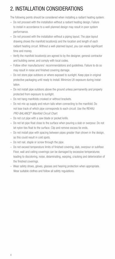
2. INSTALLATION CONSIDERATIONSThe following points should be considered when installing a radiant heating system:
– Do not proceed with the installation without a radiant heating design. Failure
to install in accordance to a well-planned design may result in poor system
performance.
– Do not proceed with the installation without a piping layout. The pipe layout
drawing shows the manifold location(s) and the location and length of each
radiant heating circuit. Without a well-planned layout, you can waste significant
time and money.
– Verify the manifold location(s) are agreed to by the designer, general contractor
and building owner, and comply with local codes.
– Follow other manufacturers’ recommendations and guidelines. Failure to do so
may result in noise and finished covering damage.
– Do not store pipe outdoors or where exposed to sunlight. Keep pipe in original
protective packaging until ready to install. Minimize UV exposure during instal-
lation.
− Do not install pipe outdoors above the ground unless permanently and properly
protected from exposure to sunlight.
– Do not hang manifolds crooked or without brackets.
– Do not mix up supply and return tails when connecting to the manifold. Do
not lose track of which pipe corresponds to each circuit. Use the REHAU
PRO-BALANCE® Manifold Circuit Chart.
– Do not cut pipe with a saw blade or pocket knife.
– Do not let pipe float close to the surface when pouring a slab or overpour. Do not
let nylon ties float to the surface. Clip and remove excess tie ends.
– Do not install pipe with spacing between pipes greater than shown in the design,
as this could result in cold spots.
– Do not nail, staple or screw through the pipe.
– Do not exceed temperature limits of finished covering, slab, overpour or subfloor.
Floor, wall and ceiling coverings can be damaged by excessive temperatures
leading to discoloring, noise, delaminating, warping, cracking and deterioration of
the finished coverings.
– Wear safety shoes, gloves, glasses and hearing protection when appropriate.
Wear suitable clothes and follow all safety regulations.

5
3. INSTALLATION OVERVIEWThe following sequence is the most efficient way to install the REHAU radiant
heating system:
1. Gather and review documents
2. Prepare and inspect job site
3. Install manifold
4. Install pipe and connect to manifold
5. Perform system air pressure test
6. Pour slab or overpour if required
7. Insulate below subfloor or suspended slab if required
8. Install finished coverings
9. Connect manifold to distribution piping and heat source
9. Flush, fill and purge the system with heating fluid
10. Adjust the system flow rates
Fig. 3.1: Typical REHAU radiant heating system installation.
RAUPEX® pipe (1); PRO-BALANCE manifold (2)
2
1

6
4. SYSTEM COMPONENTS OVERVIEWREHAU offers pipes, fittings, manifolds, heat transfer panels and plates, controls,
and a variety of installation accessories and tools. For a detailed description of our
system components, refer to the REHAU Sustainable Building Technology Product
Catalog.
– RAUPEX O2 Barrier and RAUPEX SPEED™ Pipe
– PRO-BALANCE Manifolds, Connectors and Accessories and Copper Manifolds
– RAUPANEL™ and RAUBOARD™ Heat Transfer Panels
– RAUPEX SPEED Mat
– RAUPLATE™ and Heavy Gauge Heat Transfer Plates
– REHAU Smart Controls
– Zone Controls, Thermostats and Other Controls
– EVERLOC+™ Compression-sleeve Fittings, F2080 Compression-sleeve Fittings
and Other RAUPEX Fittings and Valves
– EVERLOC+ Compression-sleeve Tools, F2080 Compression-sleeve Tools and
Other Installation Tools
– Installation Accessories and Other Hydronic Accessories

7
5. PREPARING FOR INSTALLATIONIf there are potential problems with the design and/or job site construction that
could affect the quality of the radiant heating installation or system performance,
notify the appropriate designer, contractor(s) or owner immediately.
5.1 Reviewing Local Codes
The installer is responsible for checking with applicable code authorities to deter-
mine specific local code requirements.
5.2 Gathering Documents
The radiant heating system design should be complete before attempting installa-
tion. You should have the details for the floor, wall and ceiling construction and the
schedule outlining manifold size(s) and pipe size, spacing and circuit lengths for
each heated area. Building drawings may also be necessary before proceeding with
your installation.
5.3 Inspecting the Job Site
Before beginning the installation, you should perform a site inspection.
1. Familiarize yourself with the installation sequence and scheduling for the con-
struction of the building.
Changes in the construction schedule may be required to ensure the integrity of
your installation. REHAU recommendeds that other construction that might in-
terfere with the pipe installation (e.g., drywall, plumbing) is not scheduled during
your installation. Make sure that any other work that is to follow the installation
of the radiant heating system will not damage the system components.
2. Confirm that the job site as-built matches your building plans or drawings.
Check for anything that might interfere with pipe installation such as changes to
concrete walls or footings and changes to the layout of walls or floors. Note any
changes; a redesign of the pipe layout might be required.
If pipes are to pass into rooms through doorways or follow along walls that are
not yet installed, we recommend that you use the building plans to measure and
mark their planned locations with paint or wood studs. These “virtual” walls will
act as a guide when installing pipe.

8
3. Inspect the condition of the building site.
Inspect the site for possible hazards that could damage RAUPEX pipe, such as
nails, staples, materials or tools from other trades, or chemicals that could spill
and damage the pipe. Eliminate potential hazards before installing pipe.
Confirm that the additional floor height for overpour and heat transfer panel
construction has been taken into account. Door moldings, base plates and
electrical outlets may need to be raised. Doors, thresholds and stairs may need
to be modified.
Confirm the sub-grade for the heated areas has been properly prepared. It
should be level, compacted and drained. If required, ensure the vapor barrier
and insulation are installed and per local code.
Ensure the existing subfloor or slab for heated areas is flat, level, structurally
sound, free of noise and debris before installing pipe.
A typical overpour thickness adds 13 to 17 lb/ft (63 to 80 kg/m) “dead load” to
a suspended floor structure. Confirm the floor structure has been approved to
carry this weight by an architect or engineer.
Correct any discrepancies before installing pipe.
5.4 Checking the Design
It is the full responsibility of the installer to thoroughly review the design documents
and determine the suitability of the plans for the installer's intended use prior to
ordering materials and installing the system.
1. Check the manifold locations are correct (see Section 6.1)
2. Check the orientation of the pipes in the layout is correct (see Section 9.2)
3. Check the circuit lengths are not too long (see Section 9.4)
4. Check the finished floor coverings are per the design (see Section 12.1)

9
Fig. 5.1: RAUPEX horizontal uncoiler Fig. 5.2: RAUPEX universal uncoiler
REHAU tools provide fast, easy, professional installations and are required to as-
semble REHAU compression-sleeve fittings to RAUPEX pipes. It is important to use
a proper cutter when cutting RAUPEX pipes. A clean, square cut is required.
Refer to the REHAU F2080 Compression Sleeve Product Instructions for the F2080
compression-sleeve tools.
Refer to the REHAU EVERLOC+ Assembly Product Instructions for EVERLOC+
compression-sleeve tools.
5.5 Organizing the Tools
Typical construction tools are required to complete a radiant heating system
installation.
REHAU uncoilers speed the RAUPEX pipe installation.

10
5.6 Storing and Delivering System Components
RAUPEX pipe is shipped in a cardboard box or opaque plastic bag that offers extra
protection from sunlight, rain, dirt and other hazards. Keep pipe in the box or bag
until it is required for installation, and return unused pipe to the protective packag-
ing. REHAU’s PEXa pipes must not be stored outdoors and are not designed for per-
manent outdoor installation (with the exception of non-exposed buried applications).
Refer to REHAU Technical Bulletin 218 for the accumulated maximum UV exposure
periods. Failure to follow recommendations for maximum UV exposure could result
in premature pipe failure and will negate the REHAU PEXa Limited Warranty.
REHAU fittings, manifolds, accessories and tools should be stored in a dry location.
To avoid denting and damage, store in a location with minimal traffic. Do not stack
heavy materials on top of REHAU components.
To improve the ease of installation in cold weather below 40°F (5°C), REHAU
recommends storing pipe at room temperature for a few hours before installation.
Extra care should be taken when bending cold pipe to avoid kinking.
Normal methods of packaging and protection should be exercised when shipping
and handling to prevent damage from dents, dings, abrasion, crushing and other
hazards.
11
6. INSTALLING MANIFOLDSRefer to the REHAU PRO-BALANCE Manifold Product Instructions for the installation
and operation of this manifold.
REHAU recommends installing the manifold before installing the pipe. Connect each
circuit as it is installed to avoid mixing up circuits or supply and return tails.
6.1 Best Practice for Manifold Locations
The pipe layout drawing should show the manifold location and the layout and
length of each pipe circuit to the heated areas.
Verify that manifold location is agreed to by the builder and owner. Location should
be easily accessible to facilitate installation of the RAUPEX pipe, the distribution
supply and return pipes from the heat source, wiring from thermostats to connect
to circuit actuators (if used), and for any future servicing requirements.
Manifolds should be centrally located within the heated areas for easier pipe
routing. Common locations include mechanical rooms, closets, cabinets or crawl
spaces. We recommend that manifolds be located in a heated space, but not within
an outside wall or building panel. Manifolds must be installed in a non-corrosive
environment.
Manifolds can be mounted within a stud wall and may require installation of an
access panel for later servicing.
Carefully choose the location for the manifold. Performing system pressure tests,
filling the system with fluid and purging air can sometimes result in fluids being
spilled in the area near the manifold.
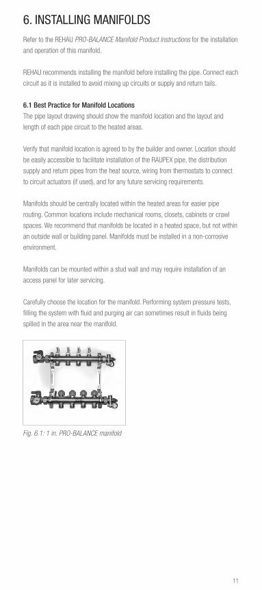
Fig. 6.1: 1 in. PRO-BALANCE manifold
12
6.2 PRO-BALANCE Manifold Installation
REHAU recommends when using an air test to slightly wet the flat gaskets with
water during assembly of the manifold. Install the manifold in the location indicated
on the plans or pipe layout drawing.
REHAU steel manifold cabinets are typically used in industrial, institutional and
commercial installations, or where required.
Fig. 6.2: PRO-BALANCE flush cabinet
for brass manifolds
Fig. 6.3: PRO-BALANCE surface cabinet
for brass manifolds
The manifold should be securely mounted, either horizontally or vertically, in its
final position. If the permanent structure does not exist (common in slab-on-grade
installations), you may have to build a temporary manifold support from wood studs
or rebar driven into the sub-grade.
Position the manifold a minimum of 16 in (40 cm) above finished floor level. A
height of 36 in (90 cm) to the top of the manifold will usually allow for convenient
pipe connections and future servicing. Make sure that the manifold is level.
Protect the manifold from damage and vandalism during and after construction.
For temporary placements, an empty RAUPEX pipe box, placed over the installed
manifold, provides some protection against weather and dirt.
The manifold should remain accessible for service after completion of the project.
6.3 Installing Protective Bend Guides Between Manifold and Slab
or Overpour
REHAU recommends the use of pipe protection where RAUPEX pipe enters the slab
or overpour at the base of a manifold. PVC bend guides hold the pipe in a 90° bend
and protect the pipe from damage by the concrete contractors and floor finishers.
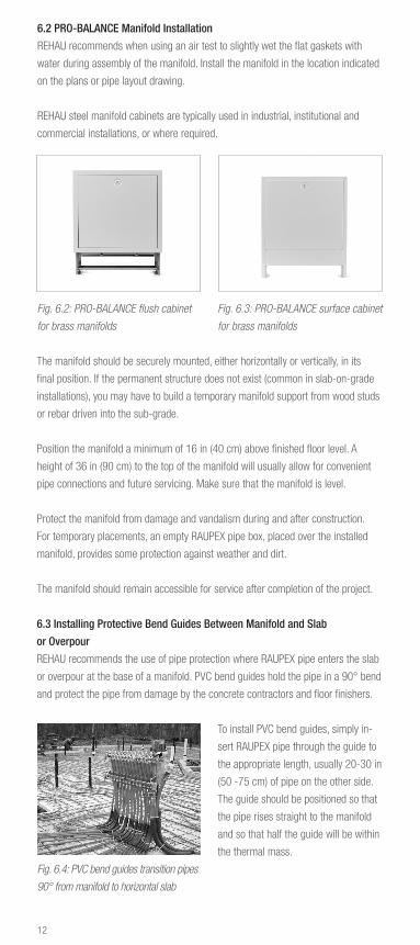
To install PVC bend guides, simply in-
sert RAUPEX pipe through the guide to
the appropriate length, usually 20-30 in
(50 -75 cm) of pipe on the other side.
The guide should be positioned so that
the pipe rises straight to the manifold
and so that half the guide will be within
the thermal mass.
Fig. 6.4: PVC bend guides transition pipes
90° from manifold to horizontal slab

13
7. CONNECTING PIPES TO MANIFOLDSAfter the manifold is securely mounted in its final position, you can begin connect-
ing the RAUPEX pipe. Connect each pipe to the manifold as it is being installed.
Attach the pipe to the upper supply header first, passing it behind the lower return
header.
Fig. 7.1: R-20 compression fitting for
connecting RAUPEX to PRO-BALANCE
manifold
Fig. 7.2: Installing pipe to manifold with
R-20 connector
1. Cut the pipe to length so there will be no stress on the manifold connection.
Make sure that the pipe is cut squarely. Attach the manifold connector to the end
of the RAUPEX pipe. When using 3/4 in. RAUPEX manifold connectors, attach
the manifold connector bushing to the manifold outlet with the hex end of the
bushing closest to the header. Thread sealant is not required.
2. Place the pipe end with attached connector up to the appropriate manifold outlet.
3. Hand-tighten the manifold compression nut connection. If the fitting is aligned
properly, it will go on smoothly. Thread sealant is not required.
4. Once the compression nut connection is hand tight, use a 1 1/4 in (32 mm)
wrench on the compression nut and do not turn more than one-half turn. (Use
a 1 1/2 in [38 mm] wrench for 3/4 in. RAUPEX manifold connectors.) Do not
over tighten, as this may destroy the integral O-ring. You may wish to tighten all
fittings at the same time once all pipes are connected.
5. All compression nut connections must be inspected for leakage after several
hours of operation. Compression nuts may need to be tightened. Do not turn
more than one-half turn. (Use a 1 1/2 in [38 mm] wrench for 3/4 in. RAUPEX
manifold connectors.) Do not over tighten, as this may destroy the integral
O-ring.
Note: After tightening, if the compression nut does not seal, remove connection and
pipe from the manifold, cut off the small section of pipe where the split ring was
and remake the connection. Before cutting the pipe, ensure there is adequate slack
in the pipe to allow for the new connection.

14
8. HANDLING PIPEWhen handling RAUPEX pipe, it is important to avoid:
– Dragging it over rough objects such as gravel or concrete
– Crushing it by driving overtop with wheelbarrow or power equipment
– Contact with oil or oily products (e.g., gasoline, paint thinner)
– Soldering operations or any open flame
– Excessive exposure to sunlight as per the allowable exposure time
8.1 Uncoiling Pipe
The uncoiler should be located in an area that will not interfere with the installation.
First, carefully cut the outer binding strings of the coiled pipe. When working with
1,000 ft (305 m) coils, cut only the outer binding strings at first. This will release
approximately half the pipe for uncoiling.
An uncoiling device such as the RAUPEX uncoiler makes it easy to unwind a pipe
coil. If you don’t have an uncoiler, have one person hold the pipe coil off the ground
between their arms while another person pulls pipe from the top or the bottom of
the coil. RAUPEX should not be pulled off of a coil that is lying flat on the ground.
Occasional twisting in the pipe may occur during installation, particularly when
installing without the benefit of an uncoiler. This must be corrected before installing
additional pipe. If the pipe becomes twisted, simply rotate the coil 90° or more, in
the direction of the twist, until the pipe lays flat.
8.2 Bending Pipe
RAUPEX pipe may be bent, even when cold. The minimum bend radius is 5X the OD
for cold bends. For an even smaller bend radius, the pipe may be heated with a hot
air gun and bent to no less than 3X the OD.
REHAU support bends make it fast and easy to create tight bends without kinking,
such as where the pipe rises out of a slab or overpour straight up to the manifold.
Pipe Size
Nominal Cold Bend Heated Bend
in in (mm) in (mm)
3/8 2.5 (64) 1.5 (38)
1/2 3.125 (79) 1.875 (48)
5/8 3.75 (95) 2.25 (57)
3/4 4.375 (111) 2.625 (67)
1 5.625 (143) 3.375 (86)
Table 8.1: Minimum 90° Bend Radius of RAUPEX Pipe

15
Pipe Size Minimum Loop Diameter = Minimum Pipe Spacing
Nominal Cold Loop Heated Loop
in. in. (mm) in. (mm)
3/8 5.0 (128) 3.0 (72)
1/2 6.25 (158) 3.75 (56)
5/8 7.5 (190) 4.5 (114)
3/4 8.75 (222) 5.25 (134)
1 11.25 (246) 6.75 (172)
Bend Diameter = 2X Bend Radius = 180° Loop
When pipes are laid out in parallel, the minimum pipe spacing is determined by the
minimum bend radius shown in Table 8.1.
Table 8.2: Minimum Parallel Pipe Spacing
8.3 Connecting Two Pipes
REHAU compression-sleeve fittings are designed for use with RAUPEX pipe and
should only be assembled with REHAU tools.
Refer to the REHAU F2080 Compression-sleeve Product Instructions for the
assembly of F2080 compression-sleeve fittings.
Refer to the REHAU EVERLOC+ Assembly Product Instructions for the assembly of
EVERLOC+ compression-sleeve fittings.
16
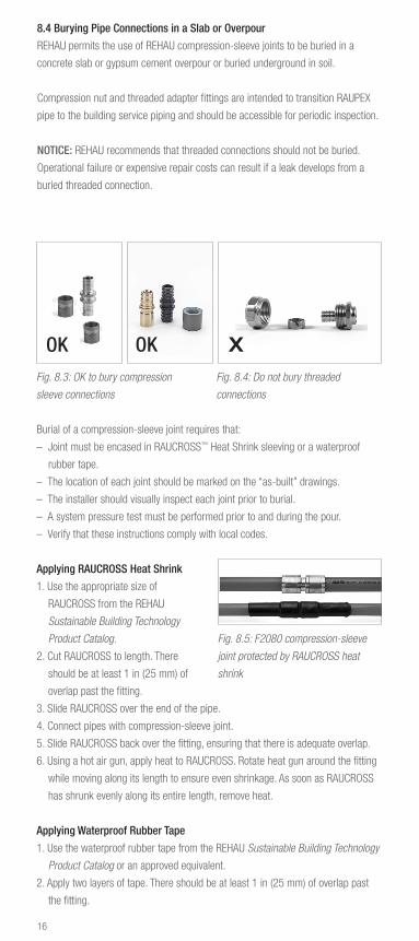
8.4 Burying Pipe Connections in a Slab or Overpour
REHAU permits the use of REHAU compression-sleeve joints to be buried in a
concrete slab or gypsum cement overpour or buried underground in soil.
Compression nut and threaded adapter fittings are intended to transition RAUPEX
pipe to the building service piping and should be accessible for periodic inspection.
NOTICE: REHAU recommends that threaded connections should not be buried.
Operational failure or expensive repair costs can result if a leak develops from a
buried threaded connection.
Fig. 8.3: OK to bury compression
sleeve connections
Fig. 8.4: Do not bury threaded
connections
OK X
Burial of a compression-sleeve joint requires that:
– Joint must be encased in RAUCROSS™ Heat Shrink sleeving or a waterproof
rubber tape.
– The location of each joint should be marked on the “as-built” drawings.
– The installer should visually inspect each joint prior to burial.
– A system pressure test must be performed prior to and during the pour.
– Verify that these instructions comply with local codes.
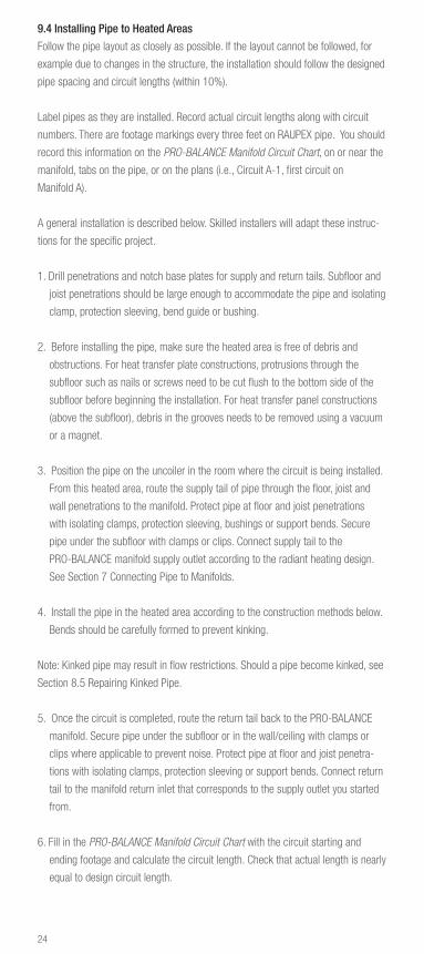
Applying RAUCROSS Heat Shrink
1. Use the appropriate size of
RAUCROSS from the REHAU
Sustainable Building Technology
Product Catalog.
2. Cut RAUCROSS to length. There
should be at least 1 in (25 mm) of
overlap past the fitting.
3. Slide RAUCROSS over the end of the pipe.
4. Connect pipes with compression-sleeve joint.
5. Slide RAUCROSS back over the fitting, ensuring that there is adequate overlap.
6. Using a hot air gun, apply heat to RAUCROSS. Rotate heat gun around the fitting
while moving along its length to ensure even shrinkage. As soon as RAUCROSS
has shrunk evenly along its entire length, remove heat.
Applying Waterproof Rubber Tape
1. Use the waterproof rubber tape from the REHAU Sustainable Building Technology
Product Catalog or an approved equivalent.
2. Apply two layers of tape. There should be at least 1 in (25 mm) of overlap past
the fitting.
Fig. 8.5: F2080 compression-sleeve
joint protected by RAUCROSS heat
shrink
OK

17
8.5 Repairing Kinked Pipe
RAUPEX pipe is flexible and resists kinking even at temperatures well below freez-
ing. If the pipe becomes kinked due to excessive bending, flow may be obstructed
or reduced. Kinked pipe must be repaired.
You can straighten the pipe by simply heating the area with a hot air gun. Rotate
the heat gun around the pipe to evenly heat the surface. Always use caution when
operating a heat gun and never use a torch or open flame to heat the pipe.
When fully heated, the pipe will get soft. When the kink is gone, turn off the heat
gun and let the area cool. (It is normal for small bubbles or wrinkles to appear
on red or blue pipe.) This type of heating will anneal or stiffen the pipe, making it
stronger but also less flexible in the heated area. Therefore, do not try to bend the
pipe in the same spot. This may require a slight adjustment of fasteners so that the
previously kinked section of pipe is installed without being bent.
8.6 Replacing Damaged Pipe
If the pipe is damaged, it might need to be replaced. Cut out the damaged area and
connect the pipes with REHAU compression-sleeve joint. In some cases it may be
necessary to use two couplings and additional pipe to replace the damaged area.
Follow the instructions in Section 8.3 Connecting Two Pipes.
A scrape in the oxygen diffusion barrier of RAUPEX O2 Barrier does not necessitate
repair with a coupling. However, when the pipe wall is gouged, the damaged section
of pipe must be removed and replaced.
8.7 Disassembling of REHAU Compression-sleeve Joints
Refer to the REHAU F2080 Compression-sleeve Product Instructions for the
disassembly of F2080 compression-sleeve fittings.
Refer to the REHAU EVERLOC+ Assembly Product Instructions for the disassembly
of EVERLOC+ fittings.

18
9. INSTALLING PIPE IN FLOOR, WALL OR CEILING
9.1 Planning Paths of Supply and Return Pipe Tails to Manifold
Review the planned paths for the pipe circuit tails to the heated area they will serve.
It may be helpful to mark the floor where the tails will be installed.
Mark all penetrations in the floor, joists and base plates for the supply and return
tails according to the design, making necessary corrections for the as-built site
conditions. Coordinate with other trades so that any floor penetrations and obstruc-
tions are clearly identified prior to installing the pipe.
WARNING! Building codes require installation of an approved firestop system
where pipes penetrate a fire-rated assembly. Fire or smoke that is not
contained may lead to death or serious injury. The installer must determine
suitability of the intended firestop system and the installer must seek out
his own licensed professional advice for any particular project. The Authority
Having Jurisdiction should review and approve the firestop system prior to
installation.
Ensure joist penetrations are in the correct locations. Normally, the center 1/3 of a
standard wood joist is the best place for drilled holes, as this is the least stressed
part of this joist type.
Note: Must check with building owner, architect, joist manufacturer and local code
officials before drilling or notching a joist to ensure the size, shape and location of
penetrations, are acceptable.
Recommend the use of PE protection sleeves or PVC bend guides in locations
where pipe enters or leaves a slab or overpour and in places where pipe might rub
against an abrasive object. Always protect pipe in steel studs.
9.2 Designing and Best Practice for Pipe Layouts
Install the pipe along exterior walls first, so that the hottest (supply) water goes to
the coldest areas.
Keep pipe at least 6 in (15 cm) from the edges of slabs, walls or other permanent
objects such as bathtubs or cabinets. This will help to prevent damage to the pipe
when these items or flooring materials are being installed. Keep pipe 6 in (15 cm)
from wax seals on toilets to prevent softening and overheating of the seals.
Pipe must not overlap when it will be embedded in a slab or overpour, as this re-
duces the slab or overpour thickness and can lead to damage of the thermal mass
or “hot spots.” Overlapping can be avoided by careful planning of the circuit paths,
ensuring that pipes can connect to manifolds without crossing each other.

19
Pipe should not be installed in areas under cabinets used for food storage or under
appliances such as freezers. It is acceptable to install pipe under bathtubs and
shower stalls to warm the bases. Pipe may be installed under cupboards on exterior
walls and under stairs.
When one circuit of pipe passes through areas with different finish coverings, the
higher R-value area will require higher water temperatures. Install pipe first under
the high R-value areas, such as carpet, then under the low R-value areas such
as tile. Alternatively, this case can be avoided by installing separate circuits under
different floor coverings.
In areas with high pipe concentrations (closer than 4 in [10 cm]) such as near
manifolds, if the thickness of the slab permits, insulate the pipes with closed-cell
foam to prevent “hot spots.” Careful planning of the pipe layout will usually prevent
this.
Pipe should be installed perpendicular to hardwood finished flooring to improve the
ease installation of the hardwood flooring and minimize chances of damaging the
pipe.
Pipe should be installed in the direction of the longest room dimension to minimize
the number of bends required, maximizing the pipe runs and making installation
easier.
Pipe circuit lengths (including supply and return tails) should be kept below the
typical values in Table 9.1 to help minimize circulator size and attain high system
efficiencies.
Pipe Typical Typical Total
Size Application Circuit Lengths
10.1 mm Dry panel systems up to 250 ft (76 m) 3/8 in.
1/2 in. Joist-space and residential slab and up to 330 ft (101m) overpour systems
5/8 in. Large residential and small commercial up to 400 ft (122 m) slab and overpour systems
3/4 in. Commercial and industrial slab systems up to 500 ft (152 m)
1 in. Large commercial and industrial slab greater than 500 ft (152 m) systems
Table 9.1: Pipe Sizes

20
9.3 Constructing Heated Areas
9.3.1 Heat Transfer Plate Floor Installation (below the subfloor in the joist space)
Plates hold the RAUPEX pipe and are installed below the structural subfloor in the
joist space of a wood framed structure. Refer to the REHAU RAUPLATE™ Product
Instructions for installation instructions.
Fig. 9.1: RAUPLATE Fig. 9.2: HG plates Fig. 9.3: LG plates
For RAUPLATE and Heavy Gauge (HG) plates, secure plates to subfloor, then snap
in pipe. For Light Gauge (LG) plates, snap pipe into plates, then secure plate to
subfloor. We recommend a 1 in (25 mm) gap between consecutive plates or a
minimum gap of 0.25 in (6 mm).
Thread pipe through holes in joists first and then connect tail to PRO-BALANCE
manifold outlet. Pull RAUPEX pipe down the length of each joist cavity before install-
ing into heat transfer plates. Start at the last joist cavity farthest from the manifold.
See Figure 9.4.
Leave a minimum 6 in (150 mm) space between the end of the pipe loop and the
end of the joist bay.
The joist space must be insulated. See Section 12.4 Insulating Suspended Floors.
Fig. 9.4: Pulling pipe circuit below subfloor in joist space
Pipe fromuncoiler
Minimum 6 in (150 mm) gap pipe loop to end of joist bay

21
9.3.2 Heat Transfer Panel Floor Installation (above the subfloor)
Panels hold RAUPEX pipe and are installed above the structural wood subfloor or
over top the structural slab in the case of RAUPANEL. Refer to the REHAU RAU-
PANEL and RAUBOARD Product Instructions for installation instructions.
Fig. 9.5: RAUPANEL Fig. 9.6: RAUBOARD
9.3.3 Heat Transfer Panel Wall or Ceiling Installation (in front of the studs
and joists)
Panels hold RAUPEX pipe and are attached to wood wall studs or wood ceiling
joists. Refer to the REHAU RAUPANEL and RAUBOARD Product Instructions for
installation instructions.
Insulate the wall or ceiling if appropriate before installing pipe. Always follow local
codes to ensure compliance with insulation minimums.
9.3.4 Structural Slab Installation
A heated structural slab consists of poured concrete surrounding the RAUPEX pipe.
The presence of pipe usually does not require re-engineering of the slab, but a
structural engineer or architect must verify this.
When using wire mesh, we recommend ordering in flat sheets instead of rolls.
Fig. 9.7: Nylon ties (1), Foam staples (2), RAILFIX™ (3),
Screw clips (4), Mounting clips (5), Universal fixing rails (6)
1 2 3
654

22
Fasteners keep pipe flat and level and prevent pipes from floating to the surface.
Foam staples or screw clips secure pipe to foam board insulation every 18 to 24 in
(45 to 60 cm).
Fixing rails are spaced at intervals of approximately 3 ft (0.91 m) and pipes snap
into the rails.
Nylon ties and mounting clips secure pipe to wire mesh. Nylon ties are used to
secure pipe to rebar. Secure pipe every 24 to 36 in (600 to 900 mm). Pipe must be
fastened at the beginning, midpoint and end of each bend. When using nylon ties,
pull them snug, but not tight. Make sure tie ends are pointed down so they will not
be exposed when the slab is poured, or cut the ends and discard.
When using steel wire ties, either use looped wire ties or ensure the ends of the
wire ties are not sharp. Additionally, the ends of the ties should be pointed down
and away from the pipe to minimize the risk of puncture. Once the pipe is tied
down, the pipe should be inspected to ensure that it is not crushed or damaged.
Subgrade should be compacted, flat and smooth to prevent damage to pipe or
insulation. Approved vapor barrier material should be installed per local code. Edge
and under slab insulation of the correct type and thickness should be installed.
Reinforcing wire mesh, if required by structural design, must be flat and level, with
all sharp ends pointing down to prevent touching the pipe.
Pipe circuits must be planned and installed to minimize passes through construc-
tion or expansion joints or other “movement” joints in the slab. With proper plan-
ning, only the supply and return pipes will pass through these areas.
Pipe circuits must also be planned and installed to minimize passes through “saw
cut” control joints in the thermal mass. Ensure that any pipes passing directly
through a control joint are installed low enough that they are below the blade of the
saw when the cut is made.
Fig. 9.8: Pipe layout in structural slab installation
Correct Layout Incorrect Layout

23
Install REHAU PE protection sleeves or equivalent around pipes that pass through
expansion, movement or control joints. Most sleeve sizes are slit for easier instal-
lation. We recommend protecting the pipe 15 in (38 cm) on both sides of the joint.
When passing the pipe below the joint, sleeving is recommended but not required.
Fig. 9.9: Pipe passing through and below movement joints in structural slabs
9.3.5 Overpour Floor Installation
An overpour consists of lightweight concrete or gypsum cement poured over an
existing structural wood subfloor or structural slab that covers the RAUPEX pipe.
Ensure the wood subfloor has been properly prepared before installing pipe to the
heated areas. For gypsum cement mixtures, apply a liquid sealant per the manufac-
turer's instructions to the wood subfloor. For lightweight concrete, cover the entire
wood subfloor and edges of base plates with PE vapor barrier to allow for expansion
and contraction of the curing concrete.
Install sleepers prior to the pour if so desired. Sleepers provide a nailing surface for
nail-down hardwood strips or planks and provide a leveling surface during the pour.
Sleepers are installed perpendicular to the direction of the hardwood flooring.
1 2 3
54
Fig. 9.10: Plastic staples (1),
RAILFIX (2), Talons (3),
Universal fixing rail (4), Steel
staples (5)
Steel staples, plastic staples or talons secure pipe to the wood subfloor every
18 to 24 in (45 to 60 cm) to keep pipes flat and level.
Fixing rails are spaced at intervals of approximately 2.5 ft (0.76 m) and pipes snap
into the rails.
REHAU recommends a minimum 3/4 in (19 mm) coverage over top of the pipe to
avoid striping and cracking.
Typically the base plates need to be doubled to provide a nailing surface for the wall
covering after the pour is completed.
24
9.4 Installing Pipe to Heated Areas
Follow the pipe layout as closely as possible. If the layout cannot be followed, for
example due to changes in the structure, the installation should follow the designed
pipe spacing and circuit lengths (within 10%).
Label pipes as they are installed. Record actual circuit lengths along with circuit
numbers. There are footage markings every three feet on RAUPEX pipe. You should
record this information on the PRO-BALANCE Manifold Circuit Chart, on or near the
manifold, tabs on the pipe, or on the plans (i.e., Circuit A-1, first circuit on
Manifold A).
A general installation is described below. Skilled installers will adapt these instruc-
tions for the specific project.
1. Drill penetrations and notch base plates for supply and return tails. Subfloor and
joist penetrations should be large enough to accommodate the pipe and isolating
clamp, protection sleeving, bend guide or bushing.
2. Before installing the pipe, make sure the heated area is free of debris and
obstructions. For heat transfer plate constructions, protrusions through the
subfloor such as nails or screws need to be cut flush to the bottom side of the
subfloor before beginning the installation. For heat transfer panel constructions
(above the subfloor), debris in the grooves needs to be removed using a vacuum
or a magnet.
3. Position the pipe on the uncoiler in the room where the circuit is being installed.
From this heated area, route the supply tail of pipe through the floor, joist and
wall penetrations to the manifold. Protect pipe at floor and joist penetrations
with isolating clamps, protection sleeving, bushings or support bends. Secure
pipe under the subfloor with clamps or clips. Connect supply tail to the
PRO-BALANCE manifold supply outlet according to the radiant heating design.
See Section 7 Connecting Pipe to Manifolds.
4. Install the pipe in the heated area according to the construction methods below.
Bends should be carefully formed to prevent kinking.
Note: Kinked pipe may result in flow restrictions. Should a pipe become kinked, see
Section 8.5 Repairing Kinked Pipe.
5. Once the circuit is completed, route the return tail back to the PRO-BALANCE
manifold. Secure pipe under the subfloor or in the wall/ceiling with clamps or
clips where applicable to prevent noise. Protect pipe at floor and joist penetra-
tions with isolating clamps, protection sleeving or support bends. Connect return
tail to the manifold return inlet that corresponds to the supply outlet you started
from.
6. Fill in the PRO-BALANCE Manifold Circuit Chart with the circuit starting and
ending footage and calculate the circuit length. Check that actual length is nearly
equal to design circuit length.
25
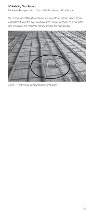
9.5 Installing Floor Sensors
For slab and overpour construction, install floor sensors before the pour.
We recommend installing floor sensors in a sleeve to make them easy to service
and replace. Ensure the sleeve end is capped. The sensor should be buried in the
slab or overpour and positioned halfway between two heating pipes.
Fig. 9.11: Floor sensor installed in sleeve of PEX pipe

26
10. TESTING THE SYSTEMA pressure test ensures the radiant heating system is leak free. The pressure test
must be performed prior to and during the installation of the slab/overpour and the
floor/wall/ceiling coverings. Tests of hydronic heating systems shall comply with
local codes and where required, shall be witnessed by the code official.
Pressure tests must be done with all circuit valves on the manifold fully open.
Pressure gauges should show pressure increments of 2 psig (20 kPa) and should
be located at or near the lowest points in the distribution system. Do not exceed the
pressure and temperature ratings of the pipe. Never exceed 150 psig (10 bar) test
pressure.
Pressure testing should be performed periodically throughout the construction of
the building. If any leak is detected during the construction phase, the leak must be
found and repaired immediately. Retest before covering the repair.
Complete inspection and test reports as required.
10.1 Air Pressure Testing
Use an air compressor that is capable of achieving the pressure test requirements.
The air supply should have an adjustable regulator to ensure the maximum pres-
sure requirements are not exceeded.
Do not perform compressed air tests on plastic fittings, plastic valves or plastic
manifolds.
Air temperature will affect the gauge pressure, so perform pressure test at a
constant temperature.
1. Verify maximum pressure requirements for all system components prior to
performing the test.
2. Install REHAU air pressure tester into the PRO-BALANCE 1 in. brass manifold
supply isolation ball valve. A transition fitting is needed to adapt the air pressure
tester to the PRO-BALANCE 1 1/4 in brass manifold. A standard air chuck will
connect to the Schrader valve on the end of tester.
3. Make sure all flow meters and balancing valves are completely open by turning
the vent key counter clockwise. Make sure the return isolation valve and the
drain valves are completely closed.
Fig. 10.1: Air pressure tester
with 1 in. MPT to connect to
PRO-BALANCE 1 in. brass manifold
27
4. Perform a preliminary pressure test pressurizing the system to the greater of
1.5 times the maximum operating pressure or 100 psig (6.9 bar) for 30 minutes.
As the pipe expands, restore pressure, first at 10 minutes and again at 20
minutes. At the end of the 30 minute preliminary test, pressure must not fall by
more than 5 psig (0.3 bar) from the maximum.
5. After performing the preliminary test, perform the main pressure test im-
mediately. The main pressure test shall last at least 2 hours. The test pressure
should be restored and must not fall more than 3 psig (0.2 bar) after 2 hours. No
leakage should be detected.
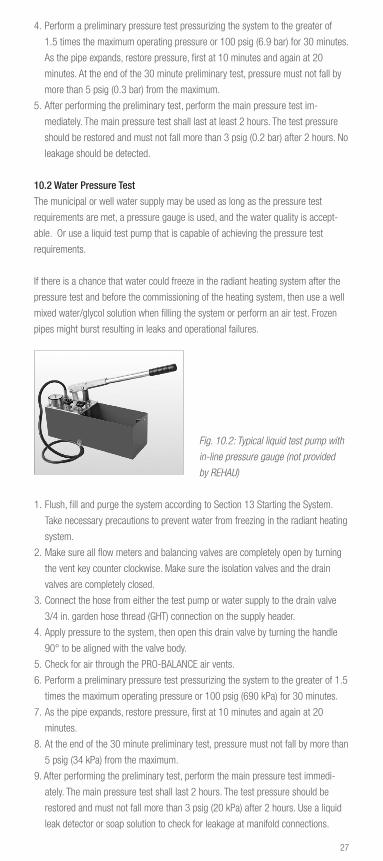
10.2 Water Pressure Test
The municipal or well water supply may be used as long as the pressure test
requirements are met, a pressure gauge is used, and the water quality is accept-
able. Or use a liquid test pump that is capable of achieving the pressure test
requirements.
If there is a chance that water could freeze in the radiant heating system after the
pressure test and before the commissioning of the heating system, then use a well
mixed water/glycol solution when filling the system or perform an air test. Frozen
pipes might burst resulting in leaks and operational failures.
Fig. 10.2: Typical liquid test pump with
in-line pressure gauge (not provided
by REHAU)
1. Flush, fill and purge the system according to Section 13 Starting the System.
Take necessary precautions to prevent water from freezing in the radiant heating
system.
2. Make sure all flow meters and balancing valves are completely open by turning
the vent key counter clockwise. Make sure the isolation valves and the drain
valves are completely closed.
3. Connect the hose from either the test pump or water supply to the drain valve
3/4 in. garden hose thread (GHT) connection on the supply header.
4. Apply pressure to the system, then open this drain valve by turning the handle
90° to be aligned with the valve body.
5. Check for air through the PRO-BALANCE air vents.
6. Perform a preliminary pressure test pressurizing the system to the greater of 1.5
times the maximum operating pressure or 100 psig (690 kPa) for 30 minutes.
7. As the pipe expands, restore pressure, first at 10 minutes and again at 20
minutes.
8. At the end of the 30 minute preliminary test, pressure must not fall by more than
5 psig (34 kPa) from the maximum.
9. After performing the preliminary test, perform the main pressure test immedi-
ately. The main pressure test shall last 2 hours. The test pressure should be
restored and must not fall more than 3 psig (20 kPa) after 2 hours. Use a liquid
leak detector or soap solution to check for leakage at manifold connections.

28
11. POURING SLAB OR OVERPOUR Slabs and overpours must be installed according to the manufacturer's instructions,
recommendations and best practices.
The pressure test should be repeated during the installation of the slab or overpour.
Pipe should be under pressure with no loss during the pour. Keep REHAU
compression-sleeve couplings, sleeves and tools on the job site in case repair is
necessary. If the pipe is damaged and these items are not available, isolate the
damaged area (at least 12 in [300 mm] in length) by building a dam or bond-out so
that a coupling can be installed later.
Before installation of the slab or overpour, the pipe must be inspected to ensure
that:
– The pipe is free of kinks and punctures.
– The pipe is fastened as described in this guide to prevent floating too close to the
top of the thermal mass. If pipe has moved due to expansion, install additional
fasteners.
– Compression-sleeve joints are sleeved in heat shrink or wrapped with two layers
of waterproof rubber tape and the buried locations are noted on plans.
– PE Protection sleeves are installed at expansion or movement joints, and any-
where that the pipe could rub against an abrasive surface.
– Nailing plates are installed above the pipe where required.
In a structural slab, the pipe must be embedded in the concrete with a minimum
of 2 in (50 mm) of coverage. In a non-structural slab or overpour, the pipe must be
embedded in the gypsum or lightweight concrete with a minimum of 3/4 in (2 cm)
of coverage.
Before the pour, notify the contractor that pipes have been installed. This will help
the contractor choose the most appropriate equipment for the project. Instruct the
contractor to make wooden “bridges” for transporting wheelbarrows over pipe and
warn that pipe could be cut or gouged by rakes or other tools used during the pour.

29
Fig. 11.1: Wooden bridges to protect pipe during pour
Ensure edge and under-slab insulation have been installed according to the design.
If insulation is less than specified or missing, then the design must be recalculated
and the installation adjusted prior to the pour.
When using nylon ties to fasten the pipe, make sure the ends are pointed down so
they will not be exposed after the slab/overpour is completed. If ties are not pointed
down, then cut the ends and pickup all the pieces before the pour.
Seal or dam all cracks and holes in the suspended subfloor to prevent the pour
from damaging the floor below.
30
12. COMPLETING THE FINISHED COVERINGFinished floor, wall and ceiling coverings must be installed according to the manu-
facturer's instructions, recommendations and best practices.
The pressure test should be repeated during the installation of the finished floor
coverings.
NOTICE: Do not nail, staple or screw into the pipe. Fasteners that contact or
penetrate the pipe may damage the pipe resulting in leaks and operational failure.
Should pipe become damaged, the section of damaged pipe must be replaced.
12.1 Design and Best Practices for Finished Coverings
Most finished coverings have a specific temperature limit. Verify products are
approved for use with radiant heating systems. Confirm that the temperature limits
set by the manufacturer of the finished coverings and associated underlayment, ad-
hesives, compounds and grouts have been taken into account. Refer to the REHAU
Radiant Heating Systems Design Guide for additional design assistance.
NOTICE: Floor, wall and ceiling coverings can be damaged by excessive tempera-
tures leading to discoloring, noise, delaminating, warping, cracking and deteriora-
tion of the finished coverings.
12.2 Floor Coverings Over Different Construction Methods
Heat Transfer Plate Installations (below the subfloor in the joist space)
– Make sure that the flooring installer is notified of the pipe locations. The flooring
installer should not use nails/screws that could pass through the subfloor and
damage or come into contact with the pipe below.
– Refer to the REHAU RAUPLATE Product Instructions for the installation of
RAUPLATE heat transfer plates.
Heat Transfer Panel Installations (above the subfloor)
– If using adhesives, apply adhesives directly to the heat transfer panels, avoiding
the pipe. Select adhesives based on the manufacturer’s instructions, materials
being bonded and the applied temperatures.
NOTICE: Do not allow adhesives to come in contact with the exterior or the interior
of the RAUPEX pipe. Chemicals may damage the pipe resulting in leaks and
operational failures.
– Basic thinset with water is acceptable in contact with the pipe as these are
comparable to the materials used in concrete and overpour installation methods.
If using a modified thinset, additives need to be checked with REHAU to maintain
the application-specific warranty.
NOTICE: Check compatibility before allowing chemicals to come in contact with the
exterior or interior of the pipe. Chemicals may damage the pipe resulting in leaks
and operational failures.

31
– Refer to the REHAU RAUBOARD or RAUPANEL Product Instructions for the instal-
lation of heat transfer panels.
– When installing an underlayment over the heat transfer panels, such as plywood,
luan or cement board, transfer the location of the pipe to the top of the underlay-
ment with a pencil or marker before securing the underlayment.
Slab and Overpour Installations
– Most solid hardwood flooring manufacturers recommend that hardwood flooring
should be installed at a moisture content close to the midpoint between the high
and low values that are expected in use. In poured (wet) radiant installations, it
can take 28 days or more for the thermal mass to cure and release the majority
of its moisture.
NOTICE: Do not deliver to the job site or install solid hardwood flooring until the
thermal mass is cured. It can absorb moisture that may cause shrinking, warping
and cupping when the heating system is activated.
12.3 Wall and Ceiling Coverings
We recommend installing stud guard steel protectors where pipes cross studs.
12.4 Insulating Suspended Floors
To ensure thermal comfort of the occupants, proper operation of the system, sound
abatement and efficient use of energy, joist spaces and suspended slabs should be
insulated after completing the pressure testing of the system.
For heat transfer panel, slab and overpour constructions, install insulation on
the underside of the subfloor with no air gap between the insulation and the
subfloor/slab.
For heat transfer plate construction, the joist space must be insulated after com-
pleting the installation and pressure testing of the system. Install insulation with
a 1 to 2 in (25 to 50 mm) air gap between the pipe and the top of the insulation.
Ensure there is no air infiltration into this air gap where heat would escape by
sealing leaks and insulating ends of joist bays.
When applying polyurethane spray foam to the joist bay the pipe must be protected
from the excessive temperatures. This is typically accomplished by first stapling
bubble foil insulation at the correct height before spraying.
Always follow local codes to ensure compliance with insulation minimums. Typical
is insulation of R-19 above heated spaces and R-30 above unheated spaces to
direct heat upward.
32
12.5 Insulating Walls and Ceilings and Other Areas
Installers need to follow the manufacturer's instructions when applying polyure-
thane spray foams to walls, ceiling and subfloors that also embed the supply and
return tails in the foam. This application may generate heat in excess of 300°F
(149°C) which exceeds the temperature rating of the RAUPEX pipe. Polyurethane
spray foams may be used over RAUPEX pipe for radiant heating applications as
long as the short-term application conditions do not exceed 210°F (99°C). REHAU
recommends applying multiple 1 in (25 mm) lifts and waiting 15 to 30 minutes
between applications until the desired thickness is achieved. Temperatures should
be monitored with a thermometer.
NOTICE: Follow all manufacturers’ instructions when applying spray foam to
RAUPEX pipe. Temperatures which exceed the rating of the pipe may damage the
pipe leading to leaks and operational failures.

33
13. STARTING THE SYSTEM
Refer to the REHAU PRO-BALANCE Brass Manifold Product Instructions for details
on starting and operating the radiant heating system.
All air must be removed from the radiant heating system and the heating fluid must
be properly selected to ensure proper operation.
13.1 Impact of Heating Fluid on Manifold and System Components
The installer must have an understanding of local water conditions and how the
heating fluid can impact the lifetime and performance of the system components.
The makeup of the heating fluid has a major impact on the potential for corrosion
within the complete system. The likelihood of corrosion and failure of system
components can be greatly reduced by using suitable water quality, ensuring that
the additives to the system including antifreeze, corrosion inhibitors and system
flushing chemicals do not lead to corrosion of the system components and ensuring
proper system operation. Measures to reduce the risk of corrosion damage are:
– Completely seal and operate system with heating water that does not contain
additives. If heating water treatment is necessary, the contractor should ensure
that additives to the system including antifreeze, corrosion inhibitors and system
flushing chemicals do not lead to corrosion of the system components. Propyl-
ene glycol and ethylene-based glycol additives at maximum 50% concentration
are recommended where freeze protection is needed. Alcohol-based glycols are
not permitted because they can lead to system failure.
– Petroleum products such as mineral oils, threading oils or incompatible air
compressor oils must not be introduced into the system. Chemicals may damage
the RAUPEX pipe resulting in leaks and operational failures.
– Foreign materials such as sand, dirt, wax and debris should not be introduced
into the system. Foreign materials may cause flow restrictions or system
component failure.
– Installer must review the complete list of water-contact materials in the REHAU
PRO-BALANCE Brass Manifold Product Instructions to ensure compatibility with
the flushing fluid, heating fluid and additional make-up water.
– Heating fluid should comply with RPA Guidelines for fluids for hydronic radiant
heating systems.
– If there are known local conditions that could lead to corrosion of the system
components, the installer must consult with a water quality expert experienced in
corrosion control of piping systems. If there are no known standards for ensuring
proper water quality, then the German engineering standard, VDI 2035 Preven-
tion of Damage in Water Heating Installations, should be referenced (English
version of VDI 2035 available for purchase at www.beuth.de or contact REHAU
for assistance).

34
13.2 Flushing, Filling and Purging the System
Use the air vent drain valves on the PRO-BALANCE manifold to fill, purge and bleed
the system. Threaded connection is for 3/4 in. garden hose thread (GHT). System
must be filled through the supply header and drained through the return header.
1. Close the isolation ball valves on the manifold supply and return headers.
2. Make sure all flow meters on the supply header are completely open by turning
the vent key counter clockwise (available on 1 in. manifold only).
3. Close all balancing valves on the return header by turning the blue cap clock-
wise.
4. Open both drain valves by turning the handle 90° degrees to be aligned with the
valve body.
5. Attach fill/drain garden hoses to each drain valve.
6. Turn on supply of clean heating water and begin filling manifold. Each circuit
should be individually purged using the circuit isolation features of the
PRO-BALANCE manifold (available on 1 in. manifold only). Use the manual air
vent on the top of each drain valve to bleed trapped air from the system. These
manual air vents may be replaced with the automatic air vent (sold separately)
for automatic venting of trapped air.
7. Open the first circuit balancing valve and circulate heating fluid until no more air
comes out.
8. When this circuit is purged, close the valve and repeat this process for the
remaining circuits.
9. When purging is complete, close the return drain valve first, then close the
supply drain valve.
10. Remove hoses and install the protective caps to the drain valves.
Fig. 13.1: Flushing, filling and purging PRO-BALANCE brass manifold with water

35
Filling Systems With Antifreeze
Certain radiant floor heating system designs require the addition of antifreeze to the
heating water for freeze and burst protection of the pipes.
Propylene glycol or ethylene-based glycol are acceptable freeze protection solu-
tions; alcohol-based glycols are not permitted because they can lead to system fail-
ure. Propylene glycol with corrosion inhibitors is recommended for safety reasons.
Verify the antifreeze complies with local codes and environmental regulations.
The amount of antifreeze must be calculated based on the freeze protection offered
by that product, and the total volume of the system. Typical applications require
20-50% antifreeze. Do not exceed 50% unless approved by the manufacturer.
It is not effective to add undiluted antifreeze into heating water that is already in the
system, as proper mixing will not occur in the relatively small system pipes. Typi-
cally the antifreeze is pre-mixed with the heating water in a barrel or bucket. Then
this heating fluid is pumped into the system.
1. Pipe system as shown above. Drop fill/drain hoses into the common bucket or
barrel.
3. Fill the barrel with the correct ratio of antifreeze and water as required.
4. Turn on submersible pump to begin pumping the heating fluid into the system.
5. Refill bucket/barrel as required to ensure no air is drawn into the submersible
pump.

36
13.3 Adjusting the System
After air has been eliminated and the hydronic circulation, mixing and distribution
systems are verified to be operational, this is the time to balance individual radiant
heating circuits for flow, as per the design. Balancing is necessary to ensure that
each circuit gets correct flow. Too much flow into a circuit will cause an area to
overheat. Too little flow will cause an area not to be warm enough.
Balancing does not mean that all circuits get the same flow. Flow requirements are
determined by the heat loss from the heated area. Adjust each circuit balancing
valve using the circuit flow requirements from the manifold circuit chart or the pipe
layout.
1. Remove blue protector cap of the circuit balancing valve. Close the valve with the
vent key by turning the control spindle clockwise until it stops. This should shut
off the circuit 100%.
2. Set the circuit flow (GPM) by turning the control spindle counter clockwise.
Note: The flow meter isolation feature should not be used for adjusting flow.
− Start with the circuit valve with the lowest flow requirement and set to the
required flow plus approximately 50%.
− Read the actual value from the corresponding flow meter on the supply
header.
3. Proceed by adjusting the remaining circuit balancing valves.
NOTICE: The valve is fully opened with 2 1/2 to 3 counter clockwise turns. Do not
allow the fine thread of the control spindle to project above the hexagon nut or
leakage will occur.
Fig. 13.2: Adjusting circuit balancing valves on PRO-BALANCE brass manifold
4. After setting all circuit valves, check the flow values on the flow meter of all
circuits. Readjust as necessary.
− To reduce flow, turn the circuit valve clockwise.
− To increase flow, turn the valve counter clockwise.
− Turn the valve slowly to see the change in flow on the flow gauge.

37
5. After balancing the manifold is complete, either install REHAU actuators or
thread the blue protective caps back on to the balancing valves by half a turn.
The cap prevents the valve from accidental adjustment and from getting dirty.
Threading the cap completely on will close the valve, but it will not change the
initial balancing adjustment of the valve.
Install the actuator hand-tight onto the manifold balancing valve. Remove the red
tab after installing the actuator. The gray position indicator on top of the actuator
allows for visual verification of the actuator’s position. When the actuator is on,
the gray indicator will rise out of the top of the actuator and be visible from the
side, and the balancing valve will open. When the actuator is off, the balancing
valve will close and the gray indicator will be flush. Refer to the REHAU 4-Wire
Manifold Valve Actuator Product Instructions for details on mounting the actua-
tors to the PRO-BALANCE brass manifold.
6. Update the PRO-BALANCE Manifold Circuit Chart and post it next to the
manifold.
Fig. 13.3: 4-wire valve actuator for
PRO-BALANCE brass manifolds

38
13.5 Maintaining the System
The radiant heating system should be inspected periodically during operation to
ensure none of the threaded connections have loosened or are leaking. A visible
leak check of all radiant heating system manifolds and pipe connections should be
conducted during every scheduled maintenance check of the heating source.
Prevent water from freezing in pipes during extended periods of power loss.
Consider freeze protection of the heating fluid.
Proper chemical maintenance should be followed for the heating fluid. Follow
manufacturers’ instructions for periodic testing, replenishment and replacement of
additives like antifreeze and corrosion inhibitors.
Adapter fittings may leak if not properly maintained. Periodically check and
retighten adapter fittings to reduce risk of leaks.
13.4 Heating the System
For pipes embedded in a slab or an overpour, the following should be applied:
– Do not operate the heating system until the slab/overpour has cured a minimum
of 28 days, unless otherwise specified and approved by the thermal mass
supplier. If it is necessary to operate the heating system to prevent freezing of
the thermal mass during curing, a maximum heating fluid temperature of 72°F
(22°C) must not be exceeded. After curing, gradually increase the heating water
temperature as described above.
– After curing of the slab/overpour and during the initial heating of the system,
increase the heating fluid temperature gradually by no more than 10°F (6°C)
each day until system reaches the required operating temperature.
– Verify allowable operating temperatures with supplier and/or installer of the slab
or overpour to ensure there are no special circumstances to consider.
Take precautions to prevent damage such as thermal shock or condensation to the
boiler from cold return water temperatures.
Monitor flows and temperatures throughout the heating system to check for air
pockets that will prevent flow. If you suspect that air is still in the system, you may
operate the manual air vents to eliminate the air. As air is eliminated, you might
need to add heating fluid. Automatic air vents can be helpful in eliminating air in the
system. Excessive air might require re-purging of the system.


www.rehau.com
For updates to this publication, visit na.rehau.com/resourcecenter The information contained herein is believed to be reliable, but no representations, guarantees or warranties of any kind are made as to its accuracy, suitability for particular applications or the results to be obtained therefrom. © 2017 REHAU
855.603 09.2017


