Reheating Process of Metal Matrix Composites forThixoforming and Their Inductive Coil Design
C.G. Kang, S.W. Youn, and P.K. Seo
(Submitted 1 June 2001; in revised form 16 October 2001)
In this work, the fabrication processes of particulate metal matrix composites (PMMCs) with a homoge-neous distribution of reinforcement and their reheating for thixoforming were studied. Electromagneticstirring was used to fabricate PMMCs to vary particle size. PMMCs were tested before and after thereheating process using a tensile test with and without heat treatment. The combined process conditionsfor fabricating the PMMCs are also suggested for a variety of particle sizes. For the thixoforming ofPMMCs, fabricated billets are reheated by using an induction heating system with a maximum capacityof 20 kW. The effects of the dispersion state of the reinforcements on the reheating temperature andmicrostructural morphology were investigated.
Improving fuel efficiency in the transportation fields, suchas automotive, vessel, and aircraft, is an important topic froman environmental point of view. From this perspective, theprocess of manufacturing lightweight products coinciding withthe requirements of the parts must be developed.[1-11] This needto reduce transportation weight has led to a major increase inthe production of metal matrix composite (MMC) engine partsfor automotive applications. Therefore, many studies on theMMCs have been actively performed. The process of manu-facturing MMC parts by thixoforming is a very promising tech-nology for manufacturing net-shape products at a relatively lowcost.
Particulate-reinforced MMCs (PMMCs) combine metallicproperties, such as toughness and ductility, with ceramic prop-erties, such as high strength wear resistance and high modulus,leading to superior strength in shear and compression. A 50%increase in modulus, achieved by substituting a discontinuoussilicon carbide-reinforced aluminum matrix composite for anunreinforced wrought aluminum alloy, resulted in a 10% re-duction in weight.[12-14]
The fabrication method of MMCs by the squeeze-castingprocess has some problems, including the homogeneous dis-persion of the particulate’s extensive interfacial reactions andparticulate fracturing during mechanical stirring,[15,16] In com-parison, the powder metallurgy method makes it easy to dis-perse the reinforcements homogeneously and to control inter-
facial reaction.[17] However, the squeeze-casting process islower in cost and is nearer to net-shape manufacturing thanpowder metallurgy.[18]
As a solution to improving the mechanical properties and toreducing manufacturing costs, PMMCs provide an opportunityfor thixoforming, which is one of the processes manufacturingnet-shaped components. In this work, both mechanical stirringand electromagnetic stirring were used to fabricate PMMCs to
C.G. Kang, School of Mechanical Engineering, Engineering ResearchCenter for Net Shape and Die Manufacturing (ERC/NSDM), PusanNational University, Pusan 609-735, Korea; and S.W. Youn and P.K.Seo, Department of Mechanical and Precision Engineering, GraduateSchool of Pusan National University, Pusan 609-735, Korea. Contacte-mail: [email protected].
152—Volume 11(2) April 2002 Journal of Materials Engineering and Performance
vary particle size. The PMMCs were tested before and afterreheating using a tensile test with and without heat treatment.The combined process condition with mechanical and electro-magnetic stirring for fabricating the PMMCs also is suggested.For the thixoforming of PMMCs, fabricated billets are reheatedby using an induction-heating device. The present study fo-cused on the influence of the dispersion state of the SiCp par-ticles on the induction heating temperature and globular mi-crostructure.
2. Experimental Procedure
2.1 Production of PMMC Billets
The matrix material used for the fabrication of PMMCs wasan aluminum alloy, A357, fabricated by the electromagneticstirring process and made by Pechiney (Voreppe, France). Thechemical composition of the A357 is shown in Table 1. Thesilicon carbide particles used in these experiments were pro-vided by Showa Denko Company (Japan), and the chemicalcomposition and PH are shown in Table 2.
Table 2 Chemical Composition of SiliconCarbide Particle
Content SiC C SiO2 Fe PH (a)
wt.% 99.0 0.04 0.55 0.07 5.0 to 7.0
(a) PH: potential of hydrogen
Table 3 Recommended Air Gaps [1/2(Di − d)] and CoilWall Thickness (dc) for Through-Heating Coils
FrequencyAir Grip
[1/2(Di = d)] (mm)Coil Wall Thickness
(dc:m)
10 kHz 3 3.225 kHz 2 1.7
Table 4 Material Properties for Calculating theComposites Properties
Material Parameter Symbol Unit Value Reference
A357 Thermalconductivity
k W/mK 152 26
Resistivity � ��m 0.0421SiCp Thermal
conductivityk W/mK 110 26
Resistivity � ��m 0.1
Fig. 2 Thermocouple positions for measuring temperature during thereheating process of metal matrix composites
Fig. 3 Schematic illustration of reheating conditions to obtain semi-solid material in metal matrix composites
Fig. 4 Microstructure of metal matrix composites fabricated by thecombined stirring process (595 °C, 15 vol.% and 600 rpm)
Journal of Materials Engineering and Performance Volume 11(2) April 2002—153
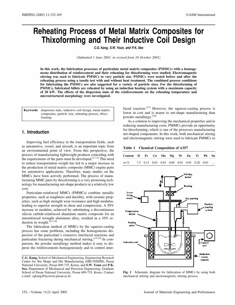
Figure 1 shows a schematic diagram of the composite stirrerdesigned and manufactured to obtain the homogeneous stirring.Mixing of SiC particles with the molten aluminum alloy A357was performed in a clay graphite crucible placed inside a high-frequency furnace. The particles had an average size of 14 �mand 25 �m and were mixed into the melt with an impeller,manufactured from graphite, that was driven by a variable DCmotor.
The characteristics of the stirring device are as follows. Theimpeller shaft was made of SUS 316. The impeller was low-ered into the melt and attached to the motor shaft. The clear-ance of the impeller from the bottom of the crucible was ap-proximately 10 mm, the melt depth being approximately 50mm. The stirrer was turned on and set to the predeterminedspeed. The top of the high-frequency furnace was covered withan adiabatic board. Thermocouples were inserted into the mol-ten alloy and the furnace to measure their exact temperatures.
The proper amount (750 to 780 g) of the matrix washed withacetone was charged into the graphite crucible placed inside ahigh-frequency furnace. The matrix was heated up to the mol-ten metal state (over 630 °C). After oxide films generated bythe contact with atmosphere were removed, the cover fixingmotor was driven to make the cover contact with the crucible.After driving the stirring impeller, the melted matrix was heldand stirred at 595 °C for 1 min. The SiC particles of 10 g perunit min were added uniformly for approximately 15 min. Thestirring impeller was coated with a fiberfrax coating cement(Carborundum Company, Amhurst, NY) and preheated up to500 °C to prevent a rapid decrease in temperature by the con-tact with the matrix. After the particle addition, the impellerwas driven for 15 min, and the melted PMMCs were poured inthe preheated graphite mold. The poured melt was cooled in themold for 1 min and then was water-quenched.
The fabricated PMMC billet diameter was 40 mm, and thelength was 180 to 200 mm. To reheat the billet, the machinedbillet length was 50 mm and diameter was 40 mm withoutmachining.
2.2 Fundamentals of Inductive Coil Design for the UniformReheating of PMMCs
Induction heating is due to eddy current heating on thesurface and requires the influence of conduction to heat thecenter of the PMMC billet. In the case of heating the PMMCbillet by using an induction heater, because the reheating con-ditions are different due to the variation of PMMCs and billetsize, the inductive coil design and construction of a quantitative
Table 5 Property Values to Calculate the Effective Coil Length of the Metal Matrix Composites with Billet Diameter 40mm and Length 50 mm, f = 20 kHz, � = 0.65 mm
Parameter Symbol Unit Value Reference
Maximum surface-center temperature difference �s − �c K 3Thermal conductivity kc W/mK 147.8Idealized power density Ps kW/m2 44.34Resistivity of PMMCs �c ��m 0.0478Magnetic constant µ H/m 4� × 107 24Angular frequency � rad/s 4 × 10⁴�Finite current depth of penetration �F m 0.78 × 10⁻³
Actual power density Pa kW/m2 47.67Thermal power Pt kW 0.256Production rate Pr Dimensionless 0.01 t/h 25Thermal capacity q kW 25.64 h/tMinimum heated surface area As m2 5.37 × 10⁻³
Billet diameter d mm 40Minimum heated length lw mm 43
Table 6 Designed Dimensions of the Induction HeatingDevice (f = 20 kHz, � = 0.65 mm)
VolumeFraction (%)
BilletDiameter(d:mm)
CoilInner
Diameter(Di:mm)
Min.HeatingLength(lw:mm)
EffectiveCoil
Length(H:mm)
5 to 15 40 44.6 42 to 44 69 to 119
Table 7 Reheating Conditions of Metal MatrixComposites for Thixoforming (SiCp 25 µm)
154—Volume 11(2) April 2002 Journal of Materials Engineering and Performance
reheating database for the thixoforming of PMMCs are veryimportant.[19-22]
In commercial induction heating systems, including the in-duction heating of aluminum billets with reinforcement, theinduced heat is normally not equally distributed over the lengthof the PMMC billet. This effect is called “skin effect.” Becauseof the skin effect, approximately 86% of the power is concen-trated in a surface layer of the inductively heated billet. Thislayer is called the current depth of penetration. The degree ofskin effect depends on the frequency and material properties,such as electrical resistivity and magnetic permeability of thePMMC billet.
Non-uniformity of the heating profile at the coil and billetsends of composites is related to the distortion of the electro-magnetic field in those areas. This distortion is called the elec-tromagnetic end effect. In general, the electromagnetic endeffect is one of the most complicated problems in inductionheating. This effect can result in either the overheating or under-heating of the billet ends. Therefore, the desired temperature dis-tribution may be obtained only with a particular coil dimension.
Fig. 6 Microstructure of metal matrix composites fabricated by thecombined stirring process (matrix temperature 595 °C, a particle sizeof 14 �m, and stirring speed of 1200 rpm)
Fig. 7 Ultimate tensile strength distribution of metal matrix compos-ites fabricated by the combined stirring process (●, before heat treat-ment, ■ after heat treatment). (a) particle size of 25 �m; (b) particlesize of 14 �m
Fig. 5 Microstructure of metal matrix composites fabricated by thecombined stirring process (matrix temperature 595 °C, a particle sizeof 25 �m, and stirring speed of 1200 rpm)
Journal of Materials Engineering and Performance Volume 11(2) April 2002—155
Fig. 8 SEM fractograph of A357/SiCp tensile specimen (a) SiCp 25 �m (b) SiCp 14 �m
Fig. 9 Set temperature and measured temperature-time curves during the reheating process of A357 billet. (a) set temperature profile; (b)temperature profile; (c) difference value between center and surface; (d) difference value between main and surface
156—Volume 11(2) April 2002 Journal of Materials Engineering and Performance
Fig. 10 Set temperature and measured temperature-time curves during the reheating process of metal matrix composites fabricated by thecombined stirring process (a particle size of 25 �m and 5 vol.%)
Fig. 11 Set temperature and measured temperature-time curves during the reheating process of metal matrix composites fabricated by thecombined stirring process (a particle size of 25 �m and 10 vol.%)
Journal of Materials Engineering and Performance Volume 11(2) April 2002—157
For a real system consisting of coil and the PMMC billet,the induced heat over the length of the PMMC billet generallyis not equally distributed and, consequently, there is a non-uniform temperature distribution. Therefore, an important pointfor coil design is to verify the correct relationship between coillength and billet length.[1,19,20,23]
To uniformly reheat PMMCs in this present work, the ef-fective coil length H and coil inner diameter, Di, of the induc-tion heating device were designed, as shown in Fig. 2. Toconsider the main surface power loss in induction heating, theidealized power density (Ps) must be represented as the actualpower density (Pa), which is modified to allow for the ratio(d/2�F) of a finite current depth of penetration (�F) of materialand billet diameter (d ).
�F =�2�c
��(Eq 1)
Pa =Ps��s − �c�idealized
�s − �c=
4.3kc��s − �c�
d(Eq 2)
In Eq 2,
�s − �c
��s − �c�idealized= k
can be obtained from the variation curves of temperature in acylinder with finite current depth of penetration,[24] where Pc,
�,W,K, and �s − �c are the resistivity of PMMCs, the magneticconstant, the angular frequency, the thermal conductivity, andthe maximum surface-center temperature difference, respec-tively.
If a diameter of 40 mm and a length of 50 mm is assumedto be reheated to 592 °C, 596 °C, and 598 °C, because, byStansel’s data (in the case of a temperature rise to 510 °C, thethermal capacity of q � 145 kW h/t and the production rate ofPr � 0.01 t/h),[25] and linear interpolation, the thermal capacityq, and the production rate Pr are calculated, and the minimumheated surface area As and the minimum heated length lw can bedetermined as follows:
As =Pt
Pa=
Pr × q
Pa(Eq 3)
lw =As
�d(Eq 4)
To determine the coil inner diameter Di and effective coillength H, recommended air gaps [1/2 (Di − d)] for through-heating coils and property values to calculate the effective coillength are shown in Tables 3-5, respectively. The propertyvalues of PMMCs with volume fraction (Vf) are calculated byEq 5 and 6:
kc = �1 − Vf� km + Vf kr (Eq 5)
�c = �1 − Vf� �m + Vf �r (Eq 6)
Fig. 12 Set temperature and measured temperature-time curves during the reheating process of metal matrix composites fabricated by thecombined stirring process (a particle size of 25 �m and 15 vol.%)
158—Volume 11(2) April 2002 Journal of Materials Engineering and Performance
where �c and kc are density and thermal conductivity of com-posites, respectively, km and kr are thermal conductivity ofmatrix and reinforcement, and �m and �r are the density ofmatrix and reinforcement, respectively.
By using linear interpolation with Table 3, the coil innerdiameter Di is calculated, and from the result of Eq 4, theeffective coil length H can be calculated by Eq 7:
H = lw + �25 to 75� (Eq 7)
Therefore, from the above considerations, the coil dimensionsfor the PMMCs reheating for thixoforming are proposed as inTable 6, and the experiments of reheating are performed byusing those dimensions.
2.3 Reheating PMMC Billets
For the thixoforming process, the reheating process ofPMMCs is very important; the process is not only necessary toperform the desired semi-solid material billet state but also tocontrol the microstructure of the PMMC billet.
PMMC billets fabricated by combined stirring weremachined to reheating process, at which point the diameterwas 40 mm and the length was 50 mm. The reheatingexperiments were executed using an induction heatingsystem with a capacity of 20 kW. The heating coil of
the induction heating system was made by with a coil di-ameter (Do) of 80 mm and a coil length (H ) of 100mm. Thermocouple holes to measure the temperatureaccurately were machined to a 2 mm diameter 10 mmfrom the surface of the billet and the position of billet depth30 mm, as shown in Fig. 2. To accurately control the tem-perature of the PMMCs, K-type CA thermocouples of 1.6 mmwere inserted into the billet. The thermocouples were cali-brated using 100 °C water. The accuracy of thermocouplesis approximately 0.2%. A data logger TDS-302 (TokyoSokki Kenkyuio Co., Ltd., Tokyo) was used to receive thedata, and the heating temperature was set to the data asa thermocouple position “main” in Fig. 2. In this study, thereheating temperature of PMMCs was determined from therelationship of the matrix temperature and solid fraction, in-cluding reinforcement.[27]
The reheating experiments were carried out for the condi-tions in Tables 7 and 8. The meanings of the symbols used inTables 7 and 8 are the same as those shown in Fig. 3.
3. Experimental Results and Discussion
3.1 Dispersion State of PMMCs
The most important point in the fabrication process ofPMMCs is the uniform dispersion of the reinforcements. The
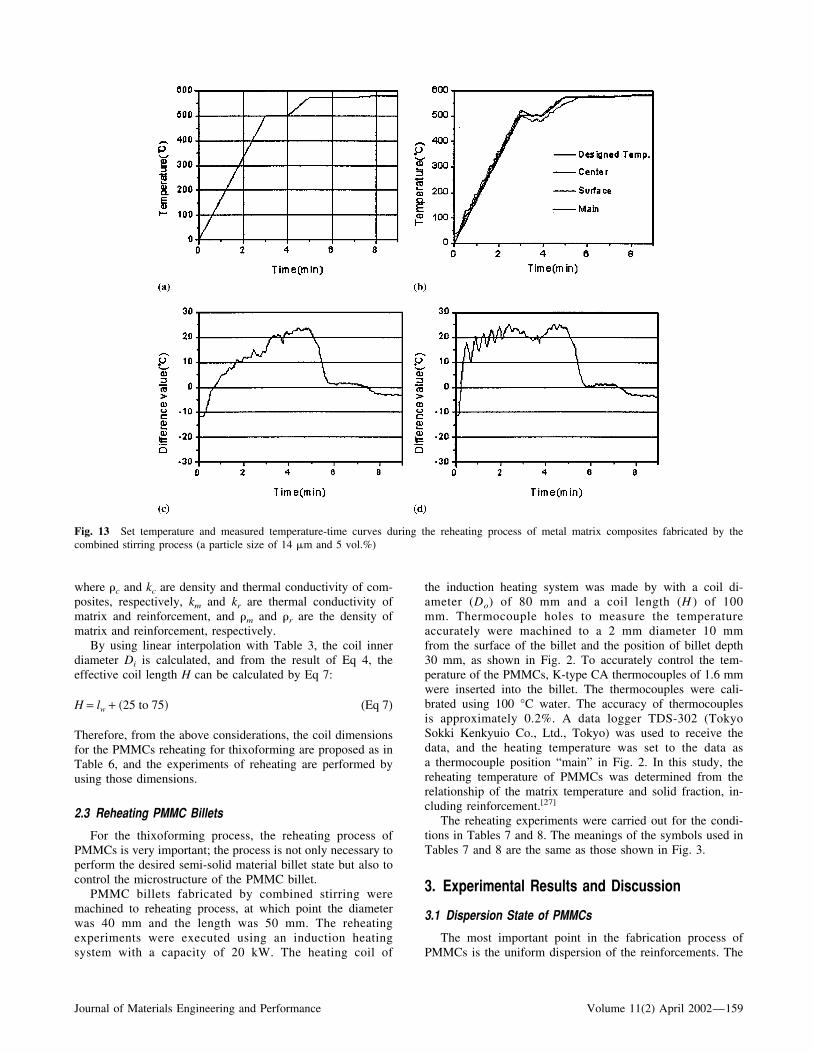
Fig. 13 Set temperature and measured temperature-time curves during the reheating process of metal matrix composites fabricated by thecombined stirring process (a particle size of 14 �m and 5 vol.%)
Journal of Materials Engineering and Performance Volume 11(2) April 2002—159
interaction parameters between SiCp and a growing solid/liquid interface are the alloying elements and the cooling rate.Particle capture or rejection is governed mainly by the Si con-tent in the matrix. In hypoeutectic alloy such as A357 wherethe Al dendrites solidify first, the particle distribution aftersolidification is dependent on the cooling rate.[28]
In these experiments, the temperature of the matrix-particulatemixture was maintained at 595 °C. The fabrication conditionswere set to obtain uniform dispersion for various stirring speeds.
Figure 4 shows the optical micrographs of obtained at astirring speed of 600 rpm with SiCp (15 vol.%). As shown inFig. 4, agglomerated SiCp particles were observed. At lowstirring speeds, the semisolid stirring process had no influenceon the uniformity of dispersion of the reinforcements.
Figures 5 and 6 present micrographs showing the dispersionstate for an increased stirring speed of 1200 rpm. As shown in Fig.5, in the case of the particle size of 25 �m, reasonably uniformdispersion was obtained, independent of volume fractions. In thecase of the particle size of 14 �m, the dispersion state of thereinforcements was not more uniform than that of the particle sizeof 25 �m. This may be explained by the particles rejected by thesolid/liquid interface. As a result of this phenomenon, the particlessegregated to the inter-dendritic region.
3.2 Mechanical Properties and Microstructure of FabricatedPMMCs
The T6 heat treatment conditions used for fabricated PMMCswere as follows. Specimens were solution heat-treated at 530 °Cfor 2 h and quenched in water. Aging was performed at 175 ° for8 h, and the specimens were air-cooled to room temperature.Tensile strength was measured on machined specimens using anMTS machine with a maximum load of 25 tons. Figure 7 showsthe ultimate strength for composites test specimen with heat treat-ment conditions (with and without T6 heat treatment). The tensilestrength increased as volume fractions increased. This phenom-enon was independent of the size of SiCp particles. However, thetensile strength decreased at a volume fraction of 15%. On atensile test, a maximum tensile strength was measured at the vol-ume fraction of 10%. This is because the bonding force betweenthe matrix and the particles in the region of clusters (position “A”in Fig. 8) is weak. Figure 8 shows the SEM fractographs ofA357/SiCp tensile specimen for two different particle sizes of 25�m and 14 �m. The preceding results show the weakness of thebonding force at the interface between the matrix and the SiCpparticles. This may be explained by many porosities (position “C”in Fig. 8) generated by air entrance in pouring the melt. Therefore,
Fig. 14 Set temperature and measured temperature-time curves during the reheating process of metal matrix composites fabricated by thecombined stirring process (a particle size of 14 �m and 10 vol.%)
160—Volume 11(2) April 2002 Journal of Materials Engineering and Performance
through the use of air vent, the interfacial bonding force wasconsidered to be improved.
3.3 Reheating Experiments
The microstructure of PMMCs after reheating must be aglobular one. Furthermore, when the PMMCs are fed from thereheating device to the die, the shape of the PMMCs must bemaintained. Therefore, the volume fraction of the reinforce-ment and SiCp particle size were considered as parameters ofthe reheating experiment to obtain the globular microstructureand a small temperature gradient. To determine the heatingtemperature of the PMMCs, the solid fraction of A357/SiCp isused as a reference.[27]
Figure 9 represents the set temperature and measured tem-perature-time curves during the reheating process of unrein-forced A357 billet. In this case, the A357 billets reach the settemperature with a small temperature difference (about 2 °C).
Figures 10-15 show the set temperature and measured tem-perature-time curves during the reheating process of metal ma-trix composites fabricated for the variation of volume fractions.In the case of 15 vol.%, the reheating temperature of PMMCswas approximately 13 °C higher than unreinforced A357. Theeffects of dispersion state of the reinforcements were observedremarkably during the reheating process of PMMCs. More-over, in the case that the SiCp particle dispersed uniformly, the
total reheating time of the PMMCs was reduced and the re-heating temperature of the final step was low.
Figure 16 presents the reheating conditions of PMMCs ac-cording to the dispersion state. In the case that the reinforce-ment dispersed uniformly, the set temperature of the final re-heating step was approximately 11 °C lower than that of thenon-uniformly dispersed reinforcements and the total reheatingtemperature of the final step was also approximately 3 minshorter than that of the non-uniformly dispersed state.
Figures 17 and 18 show the microstructures after the reheat-ing process of metal matrix composites fabricated by the semi-solid stirring process. Uniform globular microstructures with agrain size of 100 �m as well as uniformly dispersed reinforce-ments were observed at all positions.
From the proceeding results, it was found that the totalreheating time to reach the desired temperature in reheatingprocess of PMMCs depends on the dispersion state of the re-inforcements in fabricated composites billet. At the presenttime, research on obtaining a more uniform dispersion state ofthe particles by the control of solid fractions is being per-formed. Figure 19(a) and (b) shows the ultimate strength afterreheating process. As shown in Fig. 19(a) and (b), the ultimatestrength is higher than that of Fig. 7 with composites withoutreheating. After reheating of composites, it is cause that theglobularization microstructure in matrix alloy is obtained afterreheating of composite, as shown in Fig. 16 and 17.
Fig. 15 Set temperature and measured temperature-time curves during the reheating process of metal matrix composites fabricated by thecombined stirring process (a particle size of 14 �m and 15 vol.%)
Journal of Materials Engineering and Performance Volume 11(2) April 2002—161
Fig. 16 Temperature profile during the reheating process and microstructure of PMMCs after reheating process
Fig. 17 Microstructure after the reheating process of metal matrix composites fabricated by the combined stirring process (a particle size of 25 �m)
162—Volume 11(2) April 2002 Journal of Materials Engineering and Performance
4. Conclusions
Through the fabrication process of PMMCs using the com-pocasting method and the reheating experiments for thixoform-ing, the particular conclusions are summarized. The effectivecoil dimensions in the reheating process for thixoforming metalmatrix composites were proposed by the analysis method toavoid eddy current and temperature difference in an entirecross-sectional area. In the case of the particle size of 25 �m,reasonably uniform dispersion was obtained independent ofvolume fractions. In the case of the particle size of 14 �m, thedispersion state of the reinforcements was not more uniformthan that of the particle size of 25 �m. The tensile strength
increased as volume fractions increased. However, the tensilestrength decreased at a volume fraction of 15%. This is becausethe bonding force between the matrix and the particles in theregion of clusters is weak.
The SEM fractographs of A357/SiCp tensile specimen showthe weakness of the bonding force at the interface between thematrix and the SiCp particles. This may be explained by themultiple porosities generated by air entering while pouring themelt. Therefore, through the use of an air vent, the interfacialbonding force was improved. In the case that the reinforcementdispersed uniformly, the set temperature of the final reheatingstep was approximately 11 °C lower than that of the non-uniformly dispersed reinforcements and the total reheating
Fig. 18 Microstructure after the reheating process of metal matrix composites fabricated by the combined stirring process (a particle size of14 �m)
Journal of Materials Engineering and Performance Volume 11(2) April 2002—163
temperature of the final step was also approximately 3 minshorter than that of the non-uniformly dispersed state. Throughthe microstructure observation after the reheating process ofmetal matrix composites fabricated by the semisolid stirringprocess, uniform globular microstructures with a grain size of100 �m as well as uniformly dispersed reinforcements wereobserved at all positions.
In conclusion, it was found that the most important factorsregarding the reheating process of PMMCs are heating time,heating temperature, and holding time for each step duringinduction heating of composites fabricated using mechanicalstirring and electromagnetic stirring process.
Acknowledgments
This work has been supported by the Engineering ResearchCenter for Net Shape and Die Manufacturing (ERC/NSDM),which is financed jointly by the Korea Science and EngineeringFoundation (KOSEF). The financial assistance of the ERC/NSDM and KOSEF is gratefully acknowledged.
References
1. C.G. Kang and H.K. Jung: “Semisolid Forming Process—NumericalSimulation and Experimental Study,” Metall. Mater. Trans. B, 2001,32B(2), pp. 363-72.
2. C.G. Kang and H.K. Jung: “A Study on Solutions for Avoiding LiquidSegregation Phenomena in Thixoforming Process: Part I. ConstitutiveModeling and Finite Element Method Simulations for Die Design,”Metall. Mater. Trans. B, 2001, 32B(1), pp. 119-27.
3. C.G. Kang and H.K. Jung: “A Study on Solutions for Avoiding LiquidSegregation Phenomena in Thixoforming Process: Part II,” Metall.Mater. Trans. B, 2001, 32B(1), pp. 129-36.
4. C.G. Kang and H.K. Jung: “A Study on a Thixoforming Process Usingthe Thixotropic Behavior of an Aluminum Alloy with an EquiaxedMicrostructure,” J. Mater. Eng. Performance, 2000, 9(5), pp. 530-05.
5. H.K. Jung, P.K. Seo, and C.G. Kang: “Microstructural Characteristicsand Mechanical Properties of Hypo-Eutectic and Hyper-Eutectic Al-SiAlloys in the Semi-solid Forming Process,” J. Mater. ProcessingTechnol., 2001, 113, pp. 568-73.
6. H.K. Jung and C.G. Kang: “Effect of Alloying Element on the Me-chanical Behavior and Superficial Defects in Thixoforged Componentsof Al-Si Alloys,” Key Eng. Mater., 2000, 177-180, pp. 565-70.
7. A. Zavaliangos: “Modeling of the Mechanical Behavior of SemisolidMetallic Alloys at High Volume Fractions of Solid,” Int. J. Mech. Sci.,1998, 40(10), pp. 1029-41.
8. P. Giordano, F. Boero, and G. Chiarmetta: “Thixoformed Space-Frames for Series Vehicles: Study, Development and Applications,”Proc. 6th Int. Conf. on Semi-Solid Processing of Alloys and Compos-ites (SSM2000), Turin, 2000, M. Rosso and G. Chiarmetta, ed., UnioneIndustriale di Torino, Turin, Italy, 2000, pp. 29-34.
9. E. Nussbaum: “Semi-solid Forming of Aluminum and Magnesium,”Light Met. Age, 1996, June, pp. 6-22.
10. S.P. Midson, R.B. Minkler, and H.G. Brucher: “Gating of Semi-SolidAluminium Castings,” Proc. 6th Int. Conf. on Semi-Solid Processingof Alloys and Composites (SSM2000), Turin, 2000, M. Rosso and G.Chiarmetta, ed., Unione Industriale di Torino, Turin, Italy, 2000, pp.67-71.
11. E. Tzimas and A. Zavaliangos: “Mechanical Behavior of Alloys withEquiaxed Microstructure in the Semi-solid State at High Solid Con-tent,” Acta Mater., 1999, 47(2), pp. 517-28.
12. I.A. Ibrahim, F.A. Mohamed, and E.J. Lavernia: “Particulate Rein-forced Metal Matrix Composites—A Review,” J. Mater. Sci., 1991,26, pp. 1137-56.
13. S. Watanabe, K. Saithoh, and S. Okaniwa: “Extrudability of Discon-tinuous Aluminium Alloy Composite Billets,” J. Japan Inst. LightMet., 1990, 40(4), pp. 278-84.
14. T. Hikosaka: “Effect of Thermal Cycling on the Properties of Alumi-num Alloy-Alumina Short Fiber Composites Hot Extruded,” J. JapanFoundrymen’s Soc., 1994, 66(6), pp. 424-29.
15. G.A. Rozak and J.J. Lewandowski: “Effects of Casting Conditions,and Deformation Processing on A356 Aluminium and A356-20vol%SiC Composites,” J. Comp. Mater., 1992, 26(14), pp. 2076-106.
16. M. Hayashi and N. Tatsumoto: “Processing and Mechanical Propertiesof SiC Particle Dispersion Strengthened AC8A Composites by Agi-tating Casting,” J. Japan Foundrymen’s Soc., 1993, 65(11), pp. 846-52.
17. Y.H. Seo and C.G. Kang: “The Effect of Applied Pressure on Particle-Dispersion Characteristics and Mechanical Properties in Melt StirringSqueeze Cast SiCp/Al Composites,” J. Mater. Processing Technol.,1995, 55, pp. 370-79.
18. T. Yamauchi and Y. Nishida: “Infiltration Kinetics of Al-12%Si Alloyinto SiC Whiskers Preform,” J. Japan Inst. Met., 1994, 58(12), pp.1436-43.
19. H.K. Jung and C.G. Kang: “An Induction Heating Process with CoilDesign and Solutions Avoiding Coarsening Phenomena of Al-6 pctSi-3 pct Cu-0.3 pct Mg Alloy for Thixoforming,” Metall. Mater.Trans. A, 1999, 30A(11), pp. 2967-77.
20. H.K. Jung, C.G. Kang, and Y.H. Moon: “Induction Heating of Semi-Solid Billet and Control of Globular Microstructure to Prevent Coars-
Fig. 19 Ultimate strength of metal matrix composites after reheatingprocess. (� before heat treatment; � after heat treatment)
164—Volume 11(2) April 2002 Journal of Materials Engineering and Performance
ening Phenomena,” J. Mater. Eng. Performance, 2000, 9(1), pp. 12-23.
21. H.K. Jung and C.G. Kang: “Reheating Process of Cast and WroughtAluminium Alloys for Thixoforging and Their GlobularizationMechanism,” J. Mater. Processing Technol., 2000, 104(3), pp. 244-53.
22. H.K. Jung and C.G. Kang: “Finite Element Numerical SimulationModeling for Reheating Process of Semi-Solid Forming,” Key Eng.Mater., 2000, 177-180, pp. 571-76.
23. H.K. Jung and C.G. Kang: “Advanced Numerical Simulations ofSemi-Solid Forming Process,” Proc. 8th Int. Symp. on Plasticity andIts Current Applications (PLASTICITY2000), Whistler Resort, Van-couver, 2000, A.S. Khan, ed., Whistler Resort, Vancouver, 2000, pp.240-42.
24. E.J. Davies: Conduction and Induction Heating, Peter Peregrinus Ltd.,London, 1990, pp. 100-222.
25. N.R. Stansel: Induction Heating, McGraw-Hill, New York, 1949, p.178.
26. Metals Handbook, 10th ed., vol. 2, ASM International, Materials Park,OH, 1990, pp. 164-6 and 1020-2.
27. S.S. Ahn, C.G. Kang, and H.H. Jo: “Induction Heating of Metal MatrixComposites for Thixoforming,” Proc. 2nd Asia-Australasian Conf. onComposite Materials (ACCM-2000), Kyongju, 2000, Kyongju, Korea,2000, pp. 309-14.
28. H.J. Rack: Processing and Properties of Powder Metallurgy Compos-ites, The Metallurgical Society, Warrendale, PA, 1988, pp. 155.
Journal of Materials Engineering and Performance Volume 11(2) April 2002—165