his article describes a rela-tively new approach to pre-vent the accidental leakageof cargo from both above-ground storage tanks (ASTs)
and underground storage tanks (USTs).According to the American Petroleum
Institute (API), North America houses over700,000 petroleum tanks.1 Also, the U.S.Environmental Protection Agency (EPA)states there are 1.5 million ASTs.2 Severalgovernment officials and state legislators
stipulate that leak control monitoring sys-tems are the only acceptable way to pre-vent tanks from leaking into the water tableand navigable waters.
The cost of even small and undetect-ed leaks is significant: up to 8,700gallons/year/tank (33,060 liters/year/tank)for a one-gallon/hour (3.8-liter/hour) leakthat is almost impossible to detect with tra-ditionally available equipment.3 The Re-source Conservation and Recovery Act(RCRA), the Oil Pollution Act (OPA 90), andthe Clean Water Act all have regulations onASTs.4 If industries do not become moreproactive with spill and leak concerns,large fines may be levied and offendersmay be closed down.
In the “EPA Liner Study: Report toCongress”5, four liner systems were investi-gated with respect to enhancing secondarycontainment under and around ASTs andUSTs: soil, synthetic geomembrane, coatedconcrete, and steel. The report recom-mends a broad voluntary program be de-veloped for controlling and preventing con-tamination from ASTs.6 Comprehensive ASTregulations have been developed by thestates of Florida, New York, Rhode Island,
Reinforced Glass Fabric Epoxy
Linings withLeak Detection for
Storage Tanks
by Mike O’Donoghue, Ph.D., Ron Garrett, and V.J. Datta, ICI Devoe Coatings Company; KeesSwinkels, Parabeam, Holland; and Pierre Crevolin, P.Eng., CSI Coating Systems Inc.
24 MARCH 1999 / JPCL – PMC
T
Here’s a way to prevent leaks from storage tanks using linings that have their own leak detection systems.
Leak detection system installed on ASTCourtesy of ICI DevoeCoatings Company
South Dakota, Virginia, and Alaska. Cana-da’s G-55 Health and Safety Regulationsgovern the prevention of chemical waste,spillage, and leakage of potentially haz-ardous cargoes into the environment.
At a recent conference in Florida3,these four liner systems and other ways ofaddressing secondary containment issueswere brought to the foreground. In a statewhere 90% of the drinking water comesfrom the ground, the Florida DEP orga-nized a technical advisory committee to in-vestigate various secondary containmentoptions. Confronted by impending newlegislation and the requirement for the re-sponsible operation of both ASTs and USTsin conjunction with secondary containmentareas, owners and legislators alike are seek-ing secondary containment systems that arecorrosion-resistant and integrated with con-tinuous leak detection monitoring devicesfor the interstice.
U.S. regulatory agencies have advo-cated the double steel floor or “steel tank-in-tank” approach in place of lining tanksfor retrofits or for new tanks. With retrofits,new steel floors are separated from oldsteel floors by concrete or sand and theythemselves become a sacrificial anode.Ironically, once a double steel floor is in-stalled, it still requires a liner (dielectric) tostop the galvanic action; otherwise, thenew double bottom will corrode approxi-mately 4 times faster than the old bottom.7
European countries such as Austria,England, Holland, Germany, Sweden, andSwitzerland have embraced newer tech-nologies that provide secondary contain-ment within the tank structure. In Canada,too, recent research and field applicationshave shown that secondary containment in-side the tank structure can be accom-plished with a composite consisting ofepoxy-impregnated three-dimensional (3-D) glass fabric that is bonded to tankfloors. The system allows for permanentleak detection, secondary containment in-
side the primary structure itself, and achemical-resistant corrosion barrier. This ar-ticle will explain how the approach com-bines lining and leak detection technologyin new or existing tanks and how this sys-tem can provide more comprehensive leakprotection than either lined tanks or dou-ble-bottom storage tanks with leak detec-tion equipment. The discussion also ad-dresses how the system can be installed,and it gives an applicator’s perspective onthe system’s strengths and limits.
Components of the Glass Fabric-Epoxy SystemThe 3-D Glass Fabric and Leak Detection SystemOtherwise referred to as a glass yarn 3-Dglass fabric, this material was developed inEurope in 1989 using a velvet weavingtechnique that dates back to 200 BC.8 The3-D glass fabric design consists of twoidentical plain fabric decks (upper andlower) woven integrally and mechanicallytogether by means of vertical pile threads. Figure 1 shows the end view ofthe design.
The resulting fabric has a pre-set (in-terstitial) space between the two deck sur-faces. Although the fabrics are available invarious thicknesses ranging from 3 to 25millimeter (0.12 to 1 in.), the 3-millimeter(0.12-inch) version is most commonly em-ployed today. Providing a foundation for ahigher shear and compression strength lam-inate, the 3-millimeter glass fabric is also
Lining Storage Tanks
JPCL – PMC / MARCH 1999 25
Fig. 1 - End view of 3-Dglass fabric designCourtesy of Parabeam
noted for its flexibility on critical deflectionsurfaces. In addition, the flexibility of theepoxy-impregnated 3-millimeter fabric en-sures adhesion to itself and the substratebecause it readily conforms to the contoursof curved or irregular shapes. Both theamount of epoxy resin required and thefast impregnation caused by the capillaryaction of the vertical fibers in the 3-mil-
limeter fabric help reduce material andlabor costs. Each fabric deck weighs ap-proximately 280 g/m2. The weight is dis-tributed equally over the warp (lengthwise)and weft (sideways) direction. The weightof the vertical pile threads that connect theupper and lower decks depends on thethickness of the fabric and the number ofvertical piles per square meter.
Lining Storage Tanks
JPCL – PMC / MARCH 1999 27
Fig. 2 - Schematic of leak detectionsystem that monitors interstitial spaceFigures 2-5 courtesy of ZCL Composites
Fig. 4 - 3-D glass fabric AHCepoxy laminate at the criticalzone of an AST
Fig. 5 - Interstitial spacemonitoring attachment
Fig. 3 - ’Butt’ edgesof installed glassfabric and seal withstitch-mat
3 Layers 1 oz. chop strand matwetted out with AHC epoxy
1/2” or 3/8” NPT stainless steel threaded fittingwelded to a conical machined stainless steel plate
AHC epoxy topcoat
3-D glass fabric100% solidsepoxy grout
Steel substrate
Shell plate
Seal –flood coat with AHC epoxy @ 20-50 mils TDFT
100% solids epoxy grout/caulk trowelapplied to radius weld & sealedges of 3-D glass fabric
3-D glass fabric & AHC epoxycut at 45 degree adjacent to weld
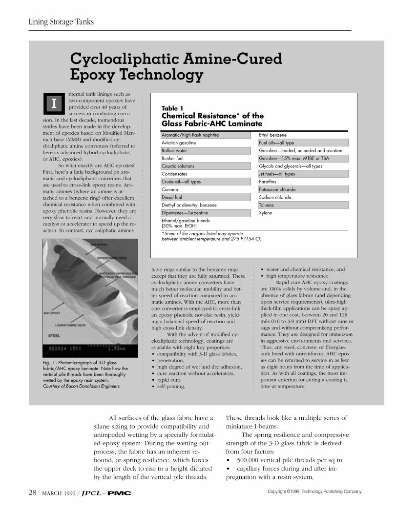
All surfaces of the glass fabric have asilane sizing to provide compatibility andunimpeded wetting by a specially formulat-ed epoxy system. During the wetting outprocess, the fabric has an inherent re-bound, or spring resilience, which forcesthe upper deck to rise to a height dictatedby the length of the vertical pile threads.
These threads look like a multiple series ofminiature I-beams.
The spring resilience and compressivestrength of the 3-D glass fabric is derivedfrom four factors:• 500,000 vertical pile threads per sq m,• capillary forces during and after im-pregnation with a resin system,
Lining Storage Tanks
28 MARCH 1999 / JPCL – PMC
Table 1Chemical Resistance* of the Glass Fabric-AHC LaminateAromatic/high flash naphtha Ethyl benzene
Aviation gasoline Fuel oils—all type
Ballast water Gasoline—leaded, unleaded and aviation
Bunker fuel Gasoline—15% max. MTBE or TBA
Caustic solutions Glycols and glycerols—all types
Condensates Jet fuels—all types
Crude oil—all types Paraffins
Cumene Potassium chloride
Diesel fuel Sodium chloride
Diethyl or dimethyl benzene Toluene
Dipentenes—Turpentine Xylene
Ethanol/gasoline blends (30% max. EtOH)
*Some of the cargoes listed may operate between ambient temperature and 275 F (154 C).
Cycloaliphatic Amine-Cured Epoxy Technologynternal tank linings such astwo-component epoxies haveprovided over 40 years ofsuccess in combating corro-
sion. In the last decade, tremendousstrides have been made in the develop-ment of epoxies based on Modified Man-nich base (MMB) and modified cy-cloaliphatic amine converters (referred tohere as advanced hybrid cycloaliphatic,or AHC, epoxies).
So what exactly are AHC epoxies?First, here’s a little background on aro-matic and cycloaliphatic converters thatare used to cross-link epoxy resins. Aro-matic amines (where an amine is at-tached to a benzene ring) offer excellentchemical resistance when combined withepoxy phenolic resins. However, they arevery slow to react and normally need acatalyst or accelerator to speed up the re-action. In contrast, cycloaliphatic amines
• water and chemical resistance, and• high temperature resistance.
Rapid cure AHC epoxy coatingsare 100% solids by volume and, in theabsence of glass fabrics (and dependingupon service requirements), ultra-highthick-film applications can be spray ap-plied in one coat, between 20 and 125mils (0.6 to 3.8 mm) DFT without runs orsags and without compromising perfor-mance. They are designed for immersionin aggressive environments and services.Thus, any steel, concrete, or fiberglasstank lined with unreinforced AHC epox-ies can be returned to service in as fewas eight hours from the time of applica-tion. As with all coatings, the most im-portant criterion for curing a coating istime-at-temperature.
have rings similar to the benzene ringsexcept that they are fully saturated. Thesecycloaliphatic amine converters havemuch better molecular mobility and bet-ter speed of reaction compared to aro-matic amines. With the AHC, more thanone converter is employed to cross-linkan epoxy phenolic novolac resin, yield-ing a balanced speed of reaction andhigh cross-link density.
With the advent of modified cy-cloaliphatic technology, coatings areavailable with eight key properties:• compatibility with 3-D glass fabrics,• penetration,• high degree of wet and dry adhesion,• cure reaction without accelerators,• rapid cure,• self-priming,
I
Fig. 1 - Photomicrograph of 3-D glass fabric/AHC epoxy laminate. Note how the vertical pile threads have been thoroughlywetted by the epoxy resin system.Courtesy of Bacon Donaldson Engineers
• the firmness with which the verticalpiles are woven into the plain fabrics, and• the composition of the glass fabric.
When the glass fabric is impregnatedwith epoxy and then fully cured, a continu-ous cavity is formed between the upperand lower deck in the laminate. The cavitylooks somewhat like the end view of corru-
gated cardboard. While the lower deck istightly adhered to the floor, the upper deckis flood-coated with solventless epoxy. Thisprocess leaves an interstitial space to becontinually monitored by a leak detectionsystem (schematically shown in Fig. 2 on p.27). This system is permeable in all direc-tions. In the event of a cargo side leak, the
Lining Storage Tanks
JPCL – PMC / MARCH 1999 29
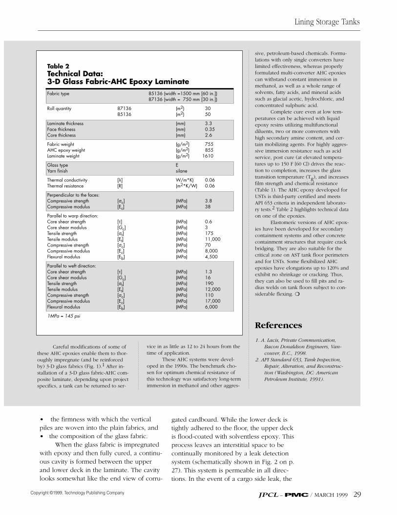
Table 2 Technical Data:3-D Glass Fabric-AHC Epoxy LaminateFabric type 85136 (width =1500 mm [60 in.])
Careful modifications of some ofthese AHC epoxies enable them to thor-oughly impregnate (and be reinforcedby) 3-D glass fabrics (Fig. 1).1 After in-stallation of a 3-D glass fabric-AHC com-posite laminate, depending upon projectspecifics, a tank can be returned to ser-
sive, petroleum-based chemicals. Formu-lations with only single converters havelimited effectiveness, whereas properlyformulated multi-converter AHC epoxiescan withstand constant immersion inmethanol, as well as a whole range ofsolvents, fatty acids, and mineral acidssuch as glacial acetic, hydrochloric, andconcentrated sulphuric acid.
Complete cure even at low tem-peratures can be achieved with liquidepoxy resins utilizing multifunctionaldiluents, two or more converters withhigh secondary amine content, and cer-tain mobilizing agents. For highly aggres-sive immersion resistance such as acidservice, post cure (at elevated tempera-tures up to 150 F [60 C]) drives the reac-tion to completion, increases the glasstransition temperature (Tg), and increasesfilm strength and chemical resistance(Table 1). The AHC epoxy developed forUSTs is third-party certified and meetsAPI 653 criteria in independent laborato-ry tests.2 Table 2 highlights technical dataon one of the epoxies.
Elastomeric versions of AHC epox-ies have been developed for secondarycontainment systems and other concretecontainment structures that require crackbridging. They are also suitable for thecritical zone on AST tank floor perimetersand for USTs. Some flexibilized AHCepoxies have elongations up to 120% andexhibit no shrinkage or cracking. Thus,they can also be used to fill pits and ra-dius welds on tank floors subject to con-siderable flexing. ❍
References
1. A. Lacis, Private Communication,Bacon Donaldson Engineers, Van-couver, B.C., 1998.
2. API Standard 653, Tank Inspection,Repair, Alteration, and Reconstruc-tion (Washington, DC: AmericanPetroleum Institute, 1991).
vice in as little as 12 to 24 hours from thetime of application.
These AHC systems were devel-oped in the 1990s. The benchmark cho-sen for optimum chemical resistance ofthis technology was satisfactory long-termimmersion in methanol and other aggres-
interstice contains leaking cargo and thespecific alarm will detect a breach beforethe cargo reaches and contaminates the en-vironment. (The alarm will also sound if aground-side leak occurs.) Appropriate re-pairs can then be carried out. Besides theleak-warning feature, the system also pro-vides corrosion protection for steel, con-crete, or fiberglass.
Several companies in North Americamake systems that utilize the 3-D glass fab-ric-epoxy technology to upgrade USTs,converting them into new double walltanks. The result is 360-degree double wallprotection with an interstitial sandwich sys-tem that combines high strength with ahigh degree of bending stiffness.9
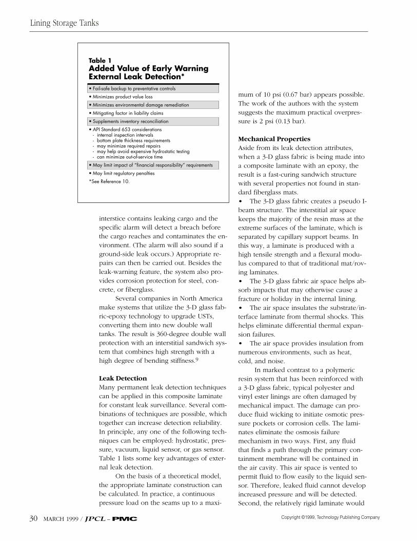
Leak DetectionMany permanent leak detection techniquescan be applied in this composite laminatefor constant leak surveillance. Several com-binations of techniques are possible, whichtogether can increase detection reliability.In principle, any one of the following tech-niques can be employed: hydrostatic, pres-sure, vacuum, liquid sensor, or gas sensor.Table 1 lists some key advantages of exter-nal leak detection.
On the basis of a theoretical model,the appropriate laminate construction canbe calculated. In practice, a continuouspressure load on the seams up to a maxi-
mum of 10 psi (0.67 bar) appears possible.The work of the authors with the systemsuggests the maximum practical overpres-sure is 2 psi (0.13 bar).
Mechanical PropertiesAside from its leak detection attributes,when a 3-D glass fabric is being made intoa composite laminate with an epoxy, theresult is a fast-curing sandwich structurewith several properties not found in stan-dard fiberglass mats.• The 3-D glass fabric creates a pseudo I-beam structure. The interstitial air spacekeeps the majority of the resin mass at theextreme surfaces of the laminate, which isseparated by capillary support beams. Inthis way, a laminate is produced with ahigh tensile strength and a flexural modu-lus compared to that of traditional mat/rov-ing laminates.• The 3-D glass fabric air space helps ab-sorb impacts that may otherwise cause afracture or holiday in the internal lining.• The air space insulates the substrate/in-terface laminate from thermal shocks. Thishelps eliminate differential thermal expan-sion failures.• The air space provides insulation fromnumerous environments, such as heat,cold, and noise.
In marked contrast to a polymericresin system that has been reinforced witha 3-D glass fabric, typical polyester andvinyl ester linings are often damaged bymechanical impact. The damage can pro-duce fluid wicking to initiate osmotic pres-sure pockets or corrosion cells. The lami-nates eliminate the osmosis failuremechanism in two ways. First, any fluidthat finds a path through the primary con-tainment membrane will be contained inthe air cavity. This air space is vented topermit fluid to flow easily to the liquid sen-sor. Therefore, leaked fluid cannot developincreased pressure and will be detected.Second, the relatively rigid laminate would
Lining Storage Tanks
30 MARCH 1999 / JPCL – PMC
Table 1Added Value of Early Warning External Leak Detection*• Fail-safe backup to preventative controls
• Minimizes product value loss
• Minimizes environmental damage remediation
• Mitigating factor in liability claims
• Supplements inventory reconciliation
• API Standard 653 considerations- internal inspection intervals- bottom plate thickness requirements- may minimize required repairs- may help avoid expensive hydrostatic testing- can minimize out-of-service time
• May limit impact of “financial responsibility” requirements
require much higher differential pressure toinduce delamination by osmosis.
Chemical and Physical PropertiesUntil recently, the 3-D glass fabrics wereusually used in conjunction with thermosetresins other than epoxy, especially isoph-thalic polyesters and vinyl esters.11 The lat-ter have better chemical resistance thanregular unsaturated polyesters and theypossess good tensile and flexural strengthcharacteristics.
Care must be exercised with selectionof anticorrosive resins because certain sys-tems cure partially or not at all in a given3-D glass fabric. The reason is a thin layerof polyvinyl ester on the vertical pile threadmay generate only a very low peakexotherm and therefore be insufficientlycured. Due to the configuration of the glassfabric, there is a large interface of resin andair. This means, on the one hand, oxygeninhibition can occur, and, on the otherhand, a large amount of styrene evaporatesfrom the vertical pile thread (so the styreneconcentration in the resin is significantly re-duced). Hence, a “low-styrene emissionresin” was normally recommended.
Epoxy ResinIdeally, an epoxy coating would solvethese problems but it has not been an easytask to develop a suitable candidate materi-al. However, recent research and molecularengineering led to the development of anew class of solventless epoxies describedas advanced hybrid cycloaliphatic epoxies(AHC).12 Further refinements of this tech-nology have enabled a critical balance tobe achieved among viscosity control,thixotropy, wetting, reaction rate, chemicalresistance, thermal resistance, and recoata-bility. At the same time, those refinementshave produced the clear resin system need-ed for visual inspection as the resin opti-mally wets out glass fabrics. Utilizing thisepoxy chemistry with 3-D glass fabrics
offers significant performance and applica-tion advantages compared to polyester,vinyl ester, and standard epoxy-based lami-nates (Table 2). The AHC technology is de-scribed in the sidebar. Table 3 summarizesthe key properties of the entire system.
ApplicationApplication EquipmentEase of application is a requirement for de-sired performance of most coatings and lin-ings, including AHC epoxies. AHC coatingsare best applied using heated twin feedplural-component spray equipment. Theymay not be particularly easy to apply un-less the contractor is properly set up withappropriate spray equipment and has expe-rience with this type of equipment andtechnology. The mixing ratios of thesecoatings are typically 2:1 and their pot livesat 77 F (25 C) are normally in the range of6 to 45 minutes.
Viscosities are temperature-depen-dent, and viscosity control is very importantfor good application. For example, an AHCepoxy can have a viscosity like honey at 77F (25 C), a viscosity similar to skim milk at100 F (38 C), and a viscosity like molassesat 40 F (4 C). One AHC epoxy coating gaveviscosity values of 19,000, 29,000, and100,000 cps at 100 (35 C), 70 (21 C), and 40F (4 C), respectively.
Some experienced applicators canand do routinely and successfully apply
Lining Storage Tanks
JPCL – PMC / MARCH 1999 31
AHC epoxies are bestapplied with heated twinfeed plural-componentspray equipmentCourtesy of ICI DevoeCoatings Company
An Applicator’s Perspectiven any AST steel floor, a leakcan develop from corrosionof the top side or the bottomside. As an applicator, wehad several questions about
the 3-D glass fabric epoxy laminate.• How strict were the surface prepara-tion requirements?• How easy to install was the 3-D fiber-glass weave/epoxy system?• What was the mechanical integrity ofthe joints between adjacent rows ofwoven material?• How was it tested before being placedin service?• How did the tank owner know thesystem was working, and was the moni-toring system subject to interpretation, orwas it simple to evaluate?
In our first two installations of thissystem, these questions were addressed.
First of all, the preparation of thesteel floor was no more stringent thanthat required for any normal internalepoxy floor coating—abrasive blast toWhite Metal, SSPC-SP 5, before applyingan epoxy primer.
Second, the installation of thefiberglass itself presented some chal-lenges because of the tank size and theparticular width of the 3-D glass fabric.The two tanks were small (i.e., 16 ft [5 m]diameter), so we couldn’t install morethan a few feet of the system at a timewithout some interruption, whether itwas a baffle, a floor fitting, or the tankshell. Using the 5-foot-wide (1.5-meter-wide) roll of 3-D glass fabric, our workers could not avoid stepping on the saturated laminate, although it would be preferable not to do so. Fortunately, this proved not to impedeour ability to install the laminate with relative ease.
One pleasant surprise was thesmall amount of effort required to work in the resin to the laminate. Thisprocess is faster and requires less laborthan normal fiberglass lining withpolyester resin.
Third, the strip over the jointsproved to be easy to install and was inte-grated into the laminate system with noproblems.
Fourth, once the laminate wasfloodcoated and the monitoring connec-tions were made, testing the integrity ofthe laminate was straightforward. A smallamount of air pressure easily located hol-idays. Holding pressure for a period oftime was a reliable indicator of total sys-tem integrity.
Fifth, we found that once a tank isput in service, it can be monitored in var-ious ways. Although it sounds sophisti-cated to talk about electronic remote
(300-g/sq m) fiberglass reinforcing matthat has been uniformly wetted with theepoxy. The fast-set repair patch shouldbe allowed to cure and then pressuretested to check for integrity. Once its in-tegrity is confirmed, the repair patchshould be scuff sanded and sealed withthe same epoxy finish described in theoriginal project specification. With thesecond approach, the wetted mat isrolled with an aluminum-ribbed roller toremove entrapped air from the laminate,produce an aesthetically acceptable sur-face, and remove excess resin in the in-terstice. In either case, the repaired areamust be properly cured before the tank isreturned to service.
Large Repair AreasDamaged areas are abrasive blasted orground out, including 6 to 8 in. (15 to 20cm) of the periphery of the damagedarea. Ideally, the lower deck of the previ-ous 3-D glass fabric-AHC epoxy installa-tion will be left firmly adhered to thesubstrate. A power grinder fitted with a24-36 grit abrasive disc can be used tofeather the perimeter of the removed area2 to 3 in. (5 to 8 cm). A uniform profilemust be maintained. The feathered andexposed edges are sealed off and filledwith a flexible 100% solids AHC epoxycaulk. While the latter is still wet, 2 to 3layers of 1-oz/sq ft (300-g/sq m) fiber-glass reinforcing mat is applied to theepoxy caulk and to exposedground/abrasive blasted surfaces.
The wetted mat is rolled with analuminum-ribbed roller to remove en-trapped air from the laminate and obtaina uniform and aesthetically acceptablesurface. While this area is still wet, thecomplete section is covered with theglass fabric and uniformly wetted out,rolling into the wet underlay and back-rolling during spray application of theepoxy. As soon as the area is cured, itshould be uniformly scuff sanded andvacuumed. At 12 in. (30 cm) intervalsaround the perimeter of the newly ap-plied laminate, holes are drilled throughthis new application and into the previ-ously installed laminate. A Forstner bit isused on the drill. The holes are vacu-umed to remove all residuals and cov-ered with clear shipping tape. Next, 2 to3 layers of AHC-impregnated 1-oz/sq ft(300-g/sq m) fiberglass reinforced mat isapplied to the entire repaired section.The wet mat is rolled as described above.After curing, the repaired area is pressuretested to confirm integrity. It is thenscuff sanded, sealed with the epoxy fin-ish specified for the whole project, andcured properly before the tank is placedin service.
monitoring to control rooms, our experi-ence is that such approaches can unnec-essarily complicate monitoring. Electronicmonitoring software or hardware can eas-ily malfunction, requiring troubleshootingof the monitoring system and risking un-detected leaks. As applicators, we are notagainst utilizing remote monitoring tech-nology, but there has to be a real advan-tage (such as remote tanks or tanks scat-tered across a large area). In normalsituations, where operators are close tothe site, a quick glance at a liquid trap orpressure gauge is simple. Monitoring canbe done simply with a small container ontop of the tank holding antifreeze, con-nected to the annular space with a flexi-ble hose. If the liquid leaves the contain-er, with the head pressure in thecontainer always higher than the pressureon the floor caused by the weight of theliquid cargo, then there is nodoubt—there is a leak.
RepairsWe also learned that repairs depended onthe type of breach in the system.
Leak DetectionIf the laminate has been damaged, or thepressure applied to the interstitial spacecannot be stabilized at the pre-deter-mined value, the following options canbe used if the leaking section is not visu-ally identifiable.• Option 1: Fill the interstitial space withcompressed air; stabilize the pressure at 2psi to 10 psi (14 kPa to 70 kPa); and wetdown the area with a soapy water solu-tion using a mop or low pressure spraygun application. Bubbling of the soap so-lution will identify the breach.• Option 2: Apply a vacuum to the inter-stice. Spray the tank floor with gaseoushelium, which is a low atomic weight,inert gas. Even the smallest pinhole willregister a loss of vacuum.
Small Area RepairsAll repairs can be carried out with coldtechniques, thus reducing risks to work-ers in confined spaces. Once a leak is lo-cated, 4 to 6 in. (10 to 15 cm) of the sur-face around the breach should befeathered back using a 24-36 grit abrasivedisc on a power grinder. The techniqueshould create a uniform profile and re-move all gloss. The exposed and pre-pared surface is vacuumed clean.
Depending on the size, the dam-aged area can be repaired with either afast-set patch version of the specifiedepoxy or two to three layers of 1-oz/sq ft
AHC epoxies with high ratio standard air-less spray equipment utilizing pre-heat andin-line heater viscosity control.
With or without 3-D glass fabric rein-forcement, these solvent-free epoxy coat-ings reduce safety hazards (source of igni-tion) and VOC concerns. In addition, theirlight colors (including a clear primer) facili-tate easy inspection when applied to ASTsand USTs.
Application (Lay Up Sequence) to an AST FloorThe tank condition and structural integritymust be carefully determined before ac-cepting it as a candidate for a 3-D glassfabric-epoxy lining. API standards 653 and652 will apply.
New or retrofitted tanks must be blastcleaned to a minimum SSPC-SP 10, NearWhite Metal Standard, and a 2- to 4-mil (50-to 100-micrometer) jagged profile obtained.For heavily pitted and corroded areas, weldseams, radiuses, and overlaps, a 100%solids epoxy caulk should be carefullyworked into these areas after applying theoptional holding primer, and immediatelybefore applying the initial coat of epoxy.This procedure is extremely important toproduce a more friendly radius and a uni-form substrate that assists in installing avoid-free application of the laminate. Theepoxy reinforcement is to be applied whilethe caulk is still wet and workable. Sincecolumns or supports in AST tanks are oncorrosion allowance pads (re-pads), the 3-D glass fabric is made to butt up to the re-pads and is grouted in place with the 100%solids epoxy caulk.
When applying AHC epoxies in con-junction with 3-D glass fabric, the initial ap-plication of the clear AHC epoxy should be20 to 30 mils (500 to 750 micrometers)WFT, immediately followed by placing the3-millimeter 3-D glass fabric into the wetepoxy. Rolling must begin immediately,using a napless serrated aluminum roller,
Lining Storage Tanks
JPCL – PMC / MARCH 1999 33
Ultrasonic Testing, Vacuum Box TestingWhen a glass AHC epoxy laminate is tobe installed inside a previously usedtank, it is highly recommended that ultra-sonic testing be conducted by a qualifiedindependent third-party inspection com-pany. The substrate should be deemedacceptable by local authorities for the in-tended service environment of the liningsystem. All welds on the entire surface tobe coated must be vacuum box tested toconfirm integrity. This requirement actu-ally applies to new or used tanks. A pin-hole in a weld will not hold air, and itwill cause a breach that is impossible todetect after the application of the glassfabric epoxy system.
It should also be noted that equip-ment currently available can ultrasonical-ly test the integrity of a steel floor after a3-D glass fabric epoxy system with inter-stitial space has been installed. Tankfloors can thus be inspected non-destruc-tively to confirm substrate integrity afterthe system has been in service for severalyears.
Cathodic ProtectionAs an applicator, I advise that all cathodicprotection systems be designed, certifiedas adequate, and installed by a corrosionspecialist. All corrosion protection sys-tems should be tested within six monthsof installation and at least every threeyears thereafter, in accordance with thecode of practice developed by a national-ly recognized organization. Impressed ca-thodic protection systems should also beinspected every 60 days to ensure thatthe system is operating properly. In theU.S., the cathodic protection systemshould be operated and maintained ac-cording to requirements specified in Title40 of the Code of Federal Regulations,Part 280.31, or according to requirementsof the implementing agency, whichever ismore stringent.
Holiday TestingHoliday testing in accordance to NACE-RP 0188-90, Discontinuity (Holiday) Test-ing of Protective Coatings, is not the opti-mum test for acceptability of a 3-D glassfabric epoxy laminate application. Thepreferred test method to confirm integrityof the laminate is to pressurize the inter-stitial space with compressed air and sta-bilize the pressure at 2 psi (0.13 bar)(maximum 5 psi [0.33 bar]) for a prede-termined amount of time (usually 4 to 6hours) without loss of pressure. If con-stant pressure is not maintained, repairguidelines must be consulted and repairprocedures undertaken. However, if dryspark holiday testing procedures are re-quested for verification of integrity, thetesting equipment should be set at 100volts per mil. ❍
and the epoxy must be workedup into the 3-D glass fabric. Thisprocedure should remove anyentrapped air, eliminate wrin-kles, and uniformly embed andwet out all the fibers of the 3-Dglass fabric.
Spray application of theepoxy should be carried out si-multaneously with back rolling,using a mohair roller to elimi-nate dry fabric, pinholing, or airentrapment. Depending on thespecified system, when the initiallay up is complete, the systemshould be no less than 90 to 125mils (2 to 3 mm) DFT, includingone layer of 3-D glass fabric.
The 3-D glass fabric shouldbe laid down in parallel coursesensuring edges/seams are buttedtightly together (maximum spaceof about 1⁄4 in. [6 mm]) and notoverlapping (Fig. 3 on p. 27).
Immediately after each parallel courseof fabric has been effectively rolled out, a4-inch- to 6-inch-wide scrim of stitch matshould be laid down, uniformly wetted,and rolled out over the butted seams of the glass fabric (Fig. 4 on p. 27). This 1 oz/10 oz combination fabric is requiredto encapsulate and seal off the glass fabric joints.
After the application has had suffi-cient time to cure (when it can be walkedon without damage), any anomalies, pro-truding strands, rough edges, or seamsmust be ground or sanded smooth. At thistime, all edges adjacent to the chime, clips,and projections should be either groundback smooth or razor cut to a 45-degreeangle to accommodate the 100% solids flex-ible grout/caulk application to seal off theinterstitial space. Also at this time, the mon-itoring plates should be installed into the 3-D E-glass application (Fig. 5 on p. 27).Final repairs, including filling air pocketsand stitch mat seams with 100% solids
epoxy grout, should also be completednow.
Next, the entire floor area should bevacuumed using a bristle brush attachmentto remove all loose particles. Sweep orblow-down cleaning alone is not accept-able. It is recommended that at this time,prior to the application of the finalflood/topcoat, an additional 8- to 12-mil(200- to 300- micrometer) DFT applicationof AHC epoxy be applied to the entire surface.
This process has proven to mitigatetiny, difficult to detect pinholes in the glassfabric reinforcement application. Once thisapplication has been allowed to sufficientlycure to the state it can be walked on with-out causing damage, a final visual inspec-tion should be performed to confirm in-tegrity prior to the application of the finalflood coat (minimum 25 to 40 mils [≈ 1mm] DFT). The final flood coat of the spec-ified system can be applied while the 100%solids flexible grout or epoxy caulk is still wet.
Lining Storage Tanks
JPCL – PMC / MARCH 1999 35
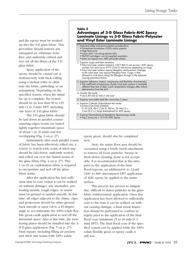
Table 2Advantages of 3-D Glass Fabric-AHC Epoxy Laminate Linings vs 3-D Glass Fabric-Polyester and Vinyl Ester Laminate Linings1. Improved safety and environmental considerations
• Solvent-free formulation (100% solids systems)• High flash point • Lower odor—no strong styrene odor• NIOSH cartridges—not air-supplied respirators• Does not require toxic MEK peroxide catalyst
2. Superior cargo and heat resistance• Poly/vinyl ester systems limited to 150 F (84 C) wet service—AHC epoxy
novolac can resist up to 275 F (154 C) wet service depending on cargo• Poly/vinyl ester systems require fiberglass reinforcement. Damage
to the outer layer may expose fiberglass hairs. Cargo is then allowed to wick down along the fiberglass through to the substrate causing premature failure
3. Superior adhesion, impact, compressive and flexibility characteristics• The coefficient of expansion of poly/vinyl ester systems is markedly
different than that of steel. Cyclic temperature changes often induce delamination from the tank
4. Greater film build• Up to 80 mils (2 mm) in one coat
5. Superior and stable shelf life—more than 2 years
6. Superior Cathodic Disbondment test results• (CAN/CSA-Z245.20-M92)
(1.5V SCE, 80 C [144 F], 48 hrs, 3% NaC1) =5 mm [0.2 in.] (avg) disbondment for AHC epoxy
7. Superior Electrochemical Impedance Spectroscopy results• Log Z (ω-sq cm) = 10.5 for AHC epoxy
The preferred test method to checkfor positive cure is time-at-temperature asoutlined on the manufacturer’s productdata sheets. A less favorable but acceptabletest for positive cure can also be deter-mined using the destructive sandpaper testmethod to test panels prepared at the sametime as the tank application. Positive curecan be established by sanding through thetop/flood coat to the 3-D glass fabric (using100 grit wet and dry sandpaper) and pro-ducing a powder. No gumming will be evi-dent on the sandpaper from the uncuredepoxy.
Depending on the technology of thespecified finish/top coat and the system’srecommended dry film thickness, Durome-ter or Barcol hardness testing can be usedto confirm through-cure. Appropriate read-ings referencing cure level can be madeavailable from the coating manufacturer.
To be acceptable, the applicationshould be free of obvious defects such assags, runs, blisters, pinholes, air-entrap-ment, fish-eyes, overspray, and any otherforeign matter entrapment. It should alsobe pressure tested.
InspectionThe last person to leave the ves-sel before installing all manwaysor covers should be a coatinginspector, who can conduct afinal inspection of system in-tegrity (through pressure test-ing). The inspector should alsoexamine the vessel for mechani-cal damage caused by removingequipment or installing inter-nals. If the vessel is damaged,repairs will be required. Thesecond sidebar gives an applica-tor’s view from the field on ap-plication, inspection, and repairtechniques. Table 4 summarizesthe lay up sequence.
Finally, it should be notedthat although the system can beapplied to sumps in AST tanks,
most owners are welding in the sumps andplacing the 3-D glass fabric epoxy directlyover them.
Summary
The 3-D glass fabric-AHC epoxy laminateprovides:• leak prevention, leak detection, andleak monitoring;• corrosion protection in aggressivechemical and thermal environments;• secondary containment within the pri-mary structure such as an AST or UST.(Therefore, the steel floor can be consid-ered the secondary containment structureand the laminate/interstice the primary con-tainment structure.);• extremely sensitive leak detection mon-itoring without risk of soil or groundwatercontamination; and• cost-effectiveness, extended service life,and inspection/maintenance requirements.(That is, the number of API 653 inspectionsmay be reduced since this system is underconstant surveillance.) ❏
Lining Storage Tanks
36 MARCH 1999 / JPCL – PMC
Table 3Key Properties of the 3-D Glass Fabric-AHCDouble Floor System
• Composite corrosion barrier and interstitial 3-D glass fabric
• Composite monolithic system that is chemically/mechanically bound together
• Completely adhered system consisting of a 100% solids AHC epoxy phenolic novolac
• Epoxy: greater thermal coefficient of expansion compatibility between steel/epoxy compared to steel/poly-vinyl ester
• High adhesion and cohesion values
• Attached to 100% cleaned and uncontaminated substrate
• Radius in critical zone—system tightly adhered; flexible caulk in critical zone
• In event of tank shift/settling—minimal damage/repair
• No fittings and mechanical fasteners
• Custom-made installations; not pre-assembled
• Split lap welds radius; lap welds all caulked with 100% solids flexible epoxy
1. Philip E. Myers, AbovegroundStorage Tanks, (McGraw-Hill,New York, NY, 1997) p. 2.
2. P.E. Del Vecchio, Jr., “AnOverview of Legislative andRegulatory Activities onAboveground Storage Tanksand Terminals,” presented atthe National Institute for Stor-age Tank Management 1stAnnual Conference onAboveground Storage Tanks,May 27-29th, 1998, Tampa,Florida.
3. M. Mott-Smith, “Florida’s Approach toAST Regulation: Chapter 62-761, F.A.C.Storage Tank Systems,” presented at theNational Institute for Storage TankManagement 1st Annual Conference onAboveground Storage Tanks, May 27-29th, 1998, Tampa, Florida.
4. P.E. Del Vecchio, Jr., “An Overview of Leg-islative and Regulatory Activities onAboveground Storage Tanks and Termi-nals,” presented at the National Institutefor Storage Tank Management 1st An-nual Conference on Aboveground Stor-age Tanks, May 27-29th, 1998, Tampa,Florida.
5. EPA Liner-Study: Report to Congress, Pub-lication 9380. 0-24.
6. K. Kapsanis and P. Markle, “The Debateover Tank Linings: Protecting Above-ground Storage Tanks and the Environ-ment,” JPCL (July 1997), 53.
7. A.R. Watson, “Aboveground Storage TankFoundations and Relocations,” present-ed at the National Institute for StorageTank Management 1st Annual Confer-ence on Aboveground Storage Tanks,May 27-29th, 1998, Tampa, Florida.
8. K. Swinkels, “Parabeam Double Wall Lin-ing for Above and Underground Tanks,”Technical Conference, JEC 96, CNIT,Paris, France, 1996.
presented at the National Institute forStorage Tank Management 1st AnnualConference on Aboveground StorageTanks, May 27-29th, 1998, Tampa, FL.
11. T.W. Cowley, “Recommended FRP In-spection Procedure for the End User,”presented at NACE-Canadian RegionWestern Conference, 1997, and COR-ROSION NACExpo ‘97, Managing Corro-sion with Plastics.
12. M. O’Donoghue, R. Garrett, V.J. Datta, P.Meli, L. Meilus, “Optimizing Performanceof Fast-Cure Epoxies for Pipe and TankLinings: Chemistry, Selection, and Appli-cation,” JPCL (March 1998), p. 36.
Editor’s Note: This article is based on apaper given at SSPC 98 in Orlando, Nov.15-19, 1998 and published in the Proceed-ings, Increasing the Value of Coatings, SSPC 98-11.
Lining Storage Tanks
JPCL – PMC / JANUARY 1999 37
Table 4Application (Lay Up Sequence) at a Glance
1. Apply 20-30 mils of clear 100% solids AHC epoxy to a clean and prepared surface.
2. Apply 3 mm (120 mils) 3-D glass fabric in the appropriate size configuration to the wetted out area and roll in with an aluminum ribbed roller.
3. Apply additional 20-30 mils (500-750 micrometers) of clear 100% solids AHC epoxy to ensure that there is full saturation and wet out of the 3-D glass fabric. Simultaneously back roll with a mohair roller during spray application.
4. Cover seams with 6 in. (15 cm) wide stitch-mat and wet out with AHC epoxy.
5. Install interstitial space monitoring attachment.
6. Test lining with a 2 psig air pressure test to ensure the lining’s integrity.
7. Flood coat the entire lining with the designated AHC epoxy finish at approximately 80-100 mils. Simultaneously back roll with a mohair roller during spray application.
8. Post-cure if necessary.
9. Again test at 2 psig air pressure to ensure the lining’s integrity.
• Mike O’Donoghue can be reached at +/604/299-7554; fax: +1/604/299-7499.
• Ron Garrett can be reached at +1/403/454- 4900; fax: +1/403/454-5245.
• V.J. Datta can be reached at +1/502/589-9340; fax: +1/502/589-5105.
• Kees Swinkel can be reached at +31/492/570625; fax: +31/492-570733.
• Pierre Crevolin can be reached at +1/403/955-2856; fax: +1/403/955-7215.