Page 1
Reinforcing Coal Mine Roof with Polyurethane Injection: 4 Case Studies
Gregory Molinda
G. Molinda
Pittsburgh Research Laboratory, National Institute for
Occupational Safety and Health (NIOSH), Cochrans Mill
Road, P. O. Box 18070, Pittsburgh, PA, USA
e-mail: [email protected]
Abstract NIOSH has recently completed a study of
the interaction between polyurethane (PUR) and coal
mine roof in order to determine the mechanism of
reinforcement, in both highly fractured rock and
unfractured rock. Four case studies of PUR rein
forcement are presented. At a West Virginia site, a
borehole camera revealed the location of roof voids
and guided the PUR injection. By injecting polyure
thane into a zone from 0.6 to 1.8 m (2–6 ft.) high in
the roof, a roof beam was created and ongoing
intersection falls were halted. In another highly
fractured roof in a western Pennsylvania mine, a
total of 5.8 cm (2.3 in.) of rubbleized rock was found
in a zone up to 3 m (10 ft.) into the roof. Untargeted
PUR injection filled approximately 1/2 of the frac
tures. These two case studies showed that it is not
necessary to fill up 100% of the void space to create
stability. In the other two field sites, polyurethane was
injected into weak, but unfractured roof. Post-injec
tion video monitoring showed that weak bedding
planes were hydraulically wedged open and polyure
thane injected along bedding. The reinforcement
value of this injection method is limited because of
the wafer-thin layer of PUR introduced along
bedding, and the lack of a PUR ‘‘webbing’’ which
would serve as a structural framework to provide
strength. It was determined that video inspection
prior to PUR injection can aid in identifying the
fracture zones to target, and minimize ‘‘blind’’
pumping and loss of PUR.
1 Background
Coal mine roof strata has been successfully rein
forced with polyurethane (PUR) for over 40 years.
Applications have included headgate stabilizations,
rock consolidation over coal panels in advance of
mining, and roof reinforcement for shield recovery.
Polyurethane injection for ground stabilization in
coal mines was first developed by the German coal
mine research organization Bergbau-Forschung
GmbH in the early 1960s (Jankowski 1972). It
became a standard stabilization method in Germany
after its commercial introduction in 1971 (Knoblauch
1994). With the introduction of the RokLok binder
system in 1977, polyurethane stabilization, particu
larly in longwall recovery, has become common in
the US (Stewart and Hesse 1985).
Polyurethane injection in coal mines is most
commonly used in difficult ground conditions includ
ing fractured rock in headgates and tailgates, and as a
stabilization remedy to prevent longwall face caving.
Page 2
It may also be used as a replacement for roof meshing
in shield recovery, and as a sealant to prevent
groundwater inflow, but often it is applied as a last
resort where conventional roof reinforcement and
support has failed.
Polyurethane is typically a two component system
that has several advantages over conventional sup
port. It has the ability to chemically bond to the rock,
unlike other supports which rely on frictional contact.
Because it is injected under pressure, it inherently
‘‘targets’’ fractures, which are the paths of least
resistance. It also has a low viscosity which allows it
to penetrate cracks as small as 0.05 mm (0.002 in.)
wide (Knoblauch 1994). It has engineered expansion
properties (1:1 to 1:12) which also allow for pene
tration (Shaller and Russell 1986). It is both strong
and plastic, preserving its’ integrity under load and
racking-type deformations (Micon 2003). Finally, it
does not obstruct roadways like standing support.
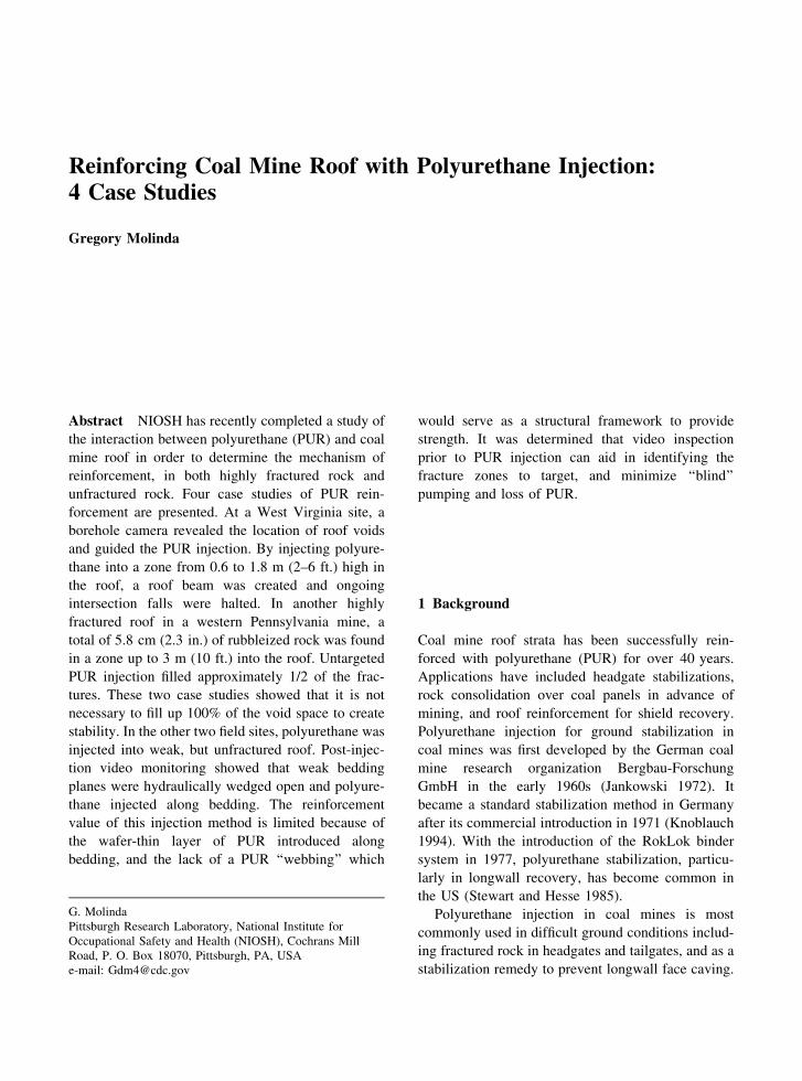
Fig. 1 Idealized PUR injection design
2 Current PUR Injection Design Process
Injection designs currently have a ‘‘one size fits all’’
approach, with drilling patterns and chemical grout
volumes decided in advance, often for the sake of
convenience rather than engineering design. A design
process is needed to determine the optimum location
for injecting polyurethane grout in order to maximize
the reinforcement benefit and prevent wasting large
volumes of chemical.
There are a number of variables which must be
considered:
1. The location of fractures—This information will
help determine the zone to target for polyure
thane injection.
2. The extent of the fracture zone—An estimation
of the total void space could be used to calculate
the volume of PUR needed. In highly fractured
roof, more test holes may be required.
3. Character of the fractures—A determination of the
nature of fractures, whether they are bedding
separations or rubbleized zones, will indicate the
permeability of the zone (Molinda 2004). Uphole
mapping of fractures will help define permeability.
4. Injection pressures—Often the injection proceeds
until a pre-determined injection pressure is
achieved, indicating that the fractures are filled.
If no back pressure is ever achieved the indica
tion is that the fracture zone is infinitely large.
Conversely, if a high back pressure is reached
immediately or very quickly, then the roof is
considered to be unfractured, and further pump
ing may hydrofracture the roof, which may
loosen roof rocks.
5. Injection arrays—These pumping patterns can
have a number of configurations. A typical
injection pattern for an intersection will have
injection holes angled over the rib on 3 m (10 ft.)
centers spanning each crosscut in the intersection
(Fig. 1). PUR may be injected over the rib on
each side of the intersection. These injection
holes will be packed off to the destabilized zone,
and then PUR is injected to erect a ‘‘grout
curtain’’ which will act as a barrier and permit
infilling of the intersection. The holes are either
pumped to a predetermined volume or pressure
or injected to refusal. Then holes will be drilled
and pumped in the center of the intersection to
complete infilling of the pattern. The exact
specifications of the design are often determined
by the experience of the contractor.
3 Case Histories
Four case histories of polyurethane injection for coal
mine roof stabilization are presented. Two of the
histories were in highly fractured rock and two were
in unfractured rock.
Page 3
3.1 West Virginia Coal Mine—Fractured Roof
A coal mine in north-central West Virginia was
experiencing extremely difficult roof conditions in its
main beltway throughout the life of the mine leading
up to the autumn of 2002 (Fig. 2). The 5.5 m (18 ft.)
wide belt entry was averaging 2–3 roof falls per year
which resulted in costly delays due to cleanup and
rehabilitation. The roof rock was extremely weak and
highly moisture-sensitive clay shale. August was the
worst month, with roof falls occurring almost 2.5
times more frequently than the annual monthly
average. In addition, it was suspected that frequent
clay veins reacted to moisture, swelled, and applied
bulking pressures on the roof sequence. The roof
began to unravel between bolts soon after mining,
leading to a progressive upward failure and finally a
roof fall. Mine-wide, 63% of roof falls occurred in
intersections. In the beltway from the portal to the first
submains, 15 of 43 intersections had fallen (Fig. 2).
Fig. 2 Roof falls and PUR injection sites in West Virginia
mine
In the beltway several generations of supplemental
support including cable bolts, roof screen, pizza pans,
posts and beams, and cribs were beginning to restrict
travel. At this point, options included adding additional
support, building a false roof, moving the beltline, or
polyurethane injection. Polyurethane injection was
selected to stabilize all the unfallen intersections in the
main beltway because, based on past experience, it had
the greatest likelihood of success.
Beltway PUR pumping began using an injection
pattern with 11 pump holes per intersection. It was
difficult to build any pump pressure and questions
immediately arose as to where the polyurethane was
going. (It should be noted that this intersection was
heavily supported with steel beams and posts). Cold
air was blowing down the test hole indicating
communication over the crosscut to the intake entry.
During injection of two test intersections on the track,
the job was stopped in order to evaluate the PUR
reinforcement by using video monitoring.
3.1.1 Video Diagnostics
A total of 16 video logs from 15 intersections were
used in the analysis. Monitoring holes were drilled on
the walkway side of the belt in the middle of the
intersection crosscut and approximately 0.9 m (3 ft.)
from the rib.
Video monitoring of the first PUR injection test
intersection on the track (intersection No. 26)
detected large voids at 2.9–3.7 m (9.5–12 ft.) up into
the roof (Fig. 3). A large void (27.9 cm (11 in.)) was
detected in two test holes in the intersection at 3.4 m
(11 ft.) above the roof line. A total of 48 cm (19 in.)
of void space was observed in the roof. From these
observations, and the lack of pump pressure, it
appeared that large volumes of PUR were being lost
into the voids. Video logs also revealed the condition
of the roof in selected intersections along the Mains
project area. Pre-pumping video logs showed signif
icant voids in the roof at two intersections (No. 23
and No. 32) (Fig. 4). At No. 32, highly fractured roof
rock was loading standing support and falling
between supports (Fig. 5). Three-3.7 m (10–12 in.)
of deflection on the steel beam in this intersection
indicates the sum of separate fracture voids up in the
roof and can be used as a de facto roof extensometer.
3.1.2 PUR Injection into the Beltway Roof
Because of the large separations detected in the roof, it
would be impossible to fill all the voids with the full
strength non-foaming PUR. After considering cavity-
filling foam, a decision was made to target zones for
reinforcement with non-foaming PUR. The concept
was that if the lower beam could be reinforced, it
would be unnecessary to fill all the voids. It was
decided to concentrate the PUR injection on reinforc
ing the roof beam from 0.6–1.8 m (2–6 ft.) up into the
roof. An injection procedure was designed which
would target two isolated zones for PUR injection,
creating a reinforced beam. The reinforced beam in
A-Mains was created by pumping PUR in an isolated
Page 4
zone from 1.2–1.8 m (4–6 ft.). The chemical was
allowed to harden (30 s set time). A packer was then
set and PUR was pumped from 0.6–1.2 m (2–4 ft.).
Each intersection averaged 12 injection holes and
these holes averaged 1.8–2.1 m (6–7 ft.) long. The
average amount of PUR injected per intersection was
1,608 l (425 gal). This volume was calculated to
allow 2.2–207.9 l (55 gal) drums of PUR mix to pump
three holes. Injection pressures ranged from 0–
13.8 MPa (0–2,000 psi) and averaged about 2.8–
3.5 MPa (400–500 psi). The injection pattern was
typically four angled holes on each side of the beltway
in the intersection, and four holes along the middle of
the intersection.
Fig. 3 Large voids detected by videoscope above bolt
anchorage
All intersections that had not fallen in the beltway
were treated with PUR injection stabilization (Fig. 2).
A total of 27 intersections had PUR injected.
3.1.3 Location of PUR After Injection into the
Beltway Roof
Video logging was available at 16 post-injection test
holes at 15 intersections. The test holes showed PUR
successfully injected into numerous void spaces in
the target zone in each of 15 intersections. Individual
cracks ranging from paper thin up to 1.9 cm
(0.75 in.) wide, and rubbleized zones up to 1.5 in.
(3.8 cm) were filled with PUR (Fig. 6). This infor
mation allowed for an intersection-by-intersection
evaluation of the PUR injection performance.
In five intersections (Nos. 20, 21, 22, 23, 32) both
pre and post-injection test holes were video-logged in
order to determine which pre-existing fractures were
filled with PUR (Figs. 4, 6). In intersections No. 21
and 23, all of the pre-existing fractures, in the zone of
reinforcement, were filled with PUR.
In intersection No. 20 and 22 pre-injection holes
showed solid roof and no voids or even separations
(Fig. 4). After injection, a video log revealed that
PUR was injected into a zone at 0.5 m (1.7 ft.) and
from 1.1–1.2 m (3.5–3.8 ft.) into the roof in hole
No. 20 (Fig. 6). It seems that in these holes PUR
was injected either into weak, unseparated bedding
planes or that it hydrofractured the bedding planes
with injection pressures up to 12.4 MPa (1,800
psi.) Hole No. 22 showed similar evidence of
hydrofracturing.
At intersection No. 32 PUR injection was less
successful. PUR injection was stopped because no
back pressures could be built up indicating flow out
of the intersection. Several centimeters of void space
was measured in the pre-injection pump zone .6–
2.1 m (2–7 ft.) into the roof) (Fig. 4). No PUR was
observed in one post-injection monitoring hole
(Fig. 6, No. 32a), indicating loss of PUR into voids.
The other post injection test hole in the intersection
showed much less severe fracturing in the target zone
at 0.6–2.1 m (2–7 ft.), with some PUR showing at
1.2 m (4 ft.). Several fractures in a zone from 0–
0.2 m (0–1 ft.) had PUR shows. PUR shows in this
zone, below the packed injection zone, indicated the
extreme fracturing in this intersection. The PUR
found fracture conduits below the packed zone and
was seen dripping from the roof. In intersection No.
32 the one pre-injection hole and two post injection
holes showed large variations in fracture location in
the intersection. This indicates that additional
Page 5
monitoring holes may be necessary to delineate the
variation in highly fractured intersections.
Fig. 4 Video logs of roof
holes in selected
intersections before PUR
injection
Fig. 5 Heavily loaded standing support and roof damage in
intersection
Table 1 summarizes the PUR injection history of
the remaining intersections. It shows the amount of
void space filled by PUR in monitoring zone (the
injection zone was from 0.6–1.8 m (2–6 ft.)) and the
amount of PUR pumped.
Of the 16 holes that were video logged in 15
intersections, 9 had 100% of the void space in the
monitoring zone 0.6–2.1 m (2–7 ft.) filled with PUR.
Six of the holes had voids filled ranging from 1–93%,
and one had no observed PUR ‘‘shows.’’ In some
intersections with multiple test holes, large differ
ences in void space were seen across the intersection
(No. 32 intersection and No. 28). In No. 28 intersec
tion four test holes in the intersection showed voids
ranging from 0–3.8 cm (0–1.5 in.) wide. The varia
tion in void space over short distances may explain
the partial filling of voids in some test holes. Even
though test holes are near injection holes, PUR may
follow a circuitous route depending on the fracture
permeability of the intersection. In three intersections
(Nos. 32, 29, 26) monitoring holes detected 0, 1 and
9% of the voids filled, indicating loss of the pumped
PUR into the mine opening or away from the
intersection monitoring hole. Monitoring holes in
each of these intersections revealed large void spaces
above the bolted horizon 1.9–15.2 cm (0.75–6 in.
wide voids). PUR injection was unsuccessful in these
instances. The intersections are currently controlled
by heavy standing support.
The amount of PUR pumped into each intersection
was also recorded. The volume ranged from 880–
2,642 l (233–699 gal) (Table 1). The location of the
PUR injection up in the roof, in regards to building a
stable roof beam, appears to be just as important as the
volume of PUR pumped per hole. If the beam is
constructed too high in the roof, then fractured rock
below it may fall. If PUR is injected too low, roof
Page 6
Fig. 6 Fractures filled with PUR in selected intersections after PUR injection
Table 1 Void space filled
by PUR in the monitoring
zone (0.6-2.1 m (2–7 ft.))
Intersection no/hole PUR
pumped l (gal)
Total void space
cm (in.) 0.6–2.1 m
(2–7 ft.) zone
No. of
injection
holes
Void space filled
(%) in test hole
0.6–2.1 m
(2–7 ft. zone)
43 2,642 (699) 0.28 (0.11) 21 100
42 2,010 (532) 3.8 (1.50) 16 100
40 2,139 (566) 1.8 (0.69) 17 100
37 2,517 (666) 1.3 (0.50) 20 100
36 2,388 (632) 7.7 (3.0) 19 100
35 2,642 (699) 7.4 (2.9) 21 100
33 1,761 (466) 4.6 (1.8) 12 71
32 880 (233) 2.2 (0.87) 8 43
32a 880 (233) 6.3 (11.8) 8 0
29 2,268 (600) 10.5 (4.1) No data 1
28 No data 0.69 (0.27) No data 93
26 2,268 (600) 6.23 (2.43) No data 9
23 1,508 (399) 2.0 (0.81) 12 54
22 1,436 (380) 0.79 (0.31) 12 100
21 1,508 (399) 2.7 (1.06) 12 100
20 1,632 (432) 1.4 (0.56) 14 100
Page 7
blocks may be dislodged. Additionally, if PUR is
injected into large voids it may migrate away from the
intersection and be of little value. Void spaces open
2.54 cm (1 in.) or more may be difficult to completely
fill with PUR. A better strategy in the beltway was to
concentrate PUR injection to building a stable beam
below these large openings. At intersection No. 26,
even though large voids exist from 3.0–4.0 m (10–
13 ft.) into the roof, a stable beam has been created
from 0.6–1.8 m (2–6 ft.) in the roof. In 2.5 years of
monitoring since the injection project, 26 of the 27
reinforced intersections were stable.
3.2 Western Pennsylvania Coal Mine—Fractured
Roof
A longwall mine in southwestern Pennsylvania was
experiencing heavy roof conditions in surrounding
rooms after a roof fall in the headgate of a future
longwall panel. It was decided to inject PUR into the
roof in order to stabilize several hundred feet of
headgate entry in preparation of the upcoming
longwall. An opportunity was presented to observe
the fracture condition of the roof before injection and
then after PUR injection. Additionally, heavy roof
conditions were observed in the center track entry
and this entry was chosen as a test site for PUR
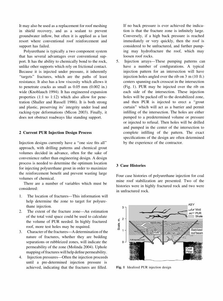
injection. Figure 7 shows the intersection where PUR
injection and monitoring took place. Five pre-injec
tion monitoring holes revealed the lithology and
fractured condition of the roof (Fig. 8). The roof
consisted of approximately 0.6 m (2 ft.) of roof coal,
followed by gray shale from 0.6–2.1 m (2–7 ft.),
followed by a coarse sandstone with coal streaks.
Fig. 7 Intersection holes monitored before and after PUR
injection
Hole No. 2 showed a total of 2.8 cm (1.1 in.) of
open void or rubbleized zones of fractured rock up in
the monitoring holes which were drilled to 3.0 m
(10 ft.). The individual cracks ranged from 0.15–
1.28 cm (0.06–0.5 in.), in bedding separations and
zones of rubble. In holes 1, 2, 3 most fractures
occurred above 1.5 m (5 ft.) and in holes 4, 5 most
fractures occurred below 1.2 m (4 ft.), indicating
some variability across the intersection. Polyurethane
was injected into five vertical holes adjacent (30–
60 cm (1–2 ft.) away) to the observation holes in the
intersection. The holes were packed at approximately
30 cm (1 ft.) above the roof line.
Figure 9 shows the logs of test holes drilled after
PUR injection. Approximately 50% of the total
fractures were filled with PUR, while the other 50%
remained open. Figure 10 shows one of the glue-
filled fractures after PUR injection. Since the holes
were packed at the bottom, the PUR was free to find
the path of least resistance up hole. Due to the
tortuous nature of the fracture permeability the PUR
found pathways which filled some fracture zones and
bypassed others, as observed in the post-PUR mon
itoring holes. From experience at the mine in West
Virginia this amount of void space filling should be
enough to stabilize the intersection. The mine was
closed shortly after the project and no assessment of
the success of the PUR stabilization project was
possible. By using multiple packed zones, as was the
case in the West Virginia project, the chances of
targeting particular zones of significant fracturing can
be greatly increased.
3.3 Bruceton Safety Research Coal Mine—
Unfractured Roof
The previous two case studies illustrate the rein
forcement mechanism of PUR in highly fractured
Page 8
rock. The remaining two cases show the behavior of
PUR when injected into unfractured rock. A test of
PUR injection was undertaken at the NIOSH Bruc
eton Safety Research Coal Mine in southwestern Pa.
The mine is located in the Pittsburgh coal bed with an
immediate roof that consists of a sequence of rider
coals and shale (Fig. 11).
Fig. 8 Pre-injection
monitoring holes in the
intersection
Fig. 9 Post-injection
monitoring holes in the
intersection
Six 2.4 m (8 ft.) long
injection holes were drilled in one intersection
(Fig. 12) into which a total of 477 kg (1,050 lbs)
(397 l (105 gal)) of polyurethane was injected. The
holes were isolated with packers located at 0.9 m
(3 ft.) up in the hole, and PUR was pumped into open
Page 9
hole from 0.9–2.4 m (3–8 ft.). Injection pressures
went as high as 8.3 MPa (1,200 psi) and averaged
about 3.5 MPa (500) psi.
Two coreholes were drilled after injection to
determine the location of the polyurethane
(Fig. 11). PUR was found injected along bedding
at 1.2 m (3.9 ft.) in corehole ACH-2 and at 1.3 m
(4.2 ft.) and 1.6 m (5.2 ft.) in ACH-3. This is
essentially the same horizon due to small variables
in the roof line. The PUR had hydrofractured the
weak bedding in the second rider coalbed and left a
1.9 cm (0.75 in.) thick plug along bedding
(Fig. 13). PUR was pumped into 1.5 m (5 ft.) of
open hole at six locations around the intersection
and the path of least resistance was the weak
bedding found in the second rider coalbed
(Fig. 11).
Fig. 10 Glue-filled fractures after PUR injection into hole 2-1
Fig. 11 Core holes drilled after PUR injection show glue
injected at &1.2 m
Fig. 12 Injection and monitoring holes at the Safety Research
Coal Mine
The results from this site indicate that, in unfrac
tured ground, multiple horizons may not be
hydrofractured and reinforced, but that only one
reinforced zone can be expected. The support value
of this zone containing a 1.9 cm (0.75 in.) layer of
PUR is questionable. If multiple zones of reinforce
ment are desired, it will be necessary to isolate each
such zone with a packer and pump the zone until
failure and injection. This may be done from several
injection holes packed at different heights or from the
same hole with multiple packers.
Page 10
Fig. 13 Polyurethane injected into roof core Ach-2 at 1.2 m
Bruceton Research Safety Coal Mine Fig. 14 PUR injected into solid roof over longwall panel
migrated back to the recovery room through a cutter
3.4 Western Pennsylvania Coal Mine—
Unfractured Roof
A western PA longwall mine was using a pre-driven
entry for longwall recovery. The entry was heavily
supported including 2.4 m (8 ft.) combination bolts,
3.7 m (12 ft.) cable bolts, double channels every row
of bolts, screen, and pumpable cribs. This heavy
support is necessary to resist the front abutment load
which will come on the room as the shearer
approaches and cuts into the room. In addition, from
the recovery room, the mine injected PUR over the
panel and also over the opposite rib side of the entry.
This was an attempt to reinforce the rock mass above
the final panel cutout prior to the longwall pass. This
rock mass would be subjected to front abutment
loading when the shearer cut into the recovery room.
Often, in weak ground, emergency PUR stabilization
is needed in the final cut-through before longwall
recovery. It was hoped that pre-grouting the roof
would head off the need for an emergency PUR
injection.
Ten feet angled ‘‘forepole’’ holes were drilled on
3.0 m (10 ft.) centers and PUR was injected in a
zone from 0.6–3.0 m (2–10 ft.) into the roof rock at
45� over the panel. High pressures were built up and
it was extremely difficult to force PUR into the
tight, unfractured rock. PUR migrated back towards
the recovery room and was observed leaking into the
room via a cutter developed on the panel side of the
room during development (Fig. 14). No observation
was possible over the panel, but it is clear that PUR
could not migrate over the solid panel as originally
planned, but hydrofractured a weak bedding plane and
followed the path of least resistance back into the
entry. Two adjacent recovery chutes off of the
recovery room were also selected for a test of the
injection of PUR into unfractured, but undermined,
roof rock. Chutes C and D were injected with PUR and
the results monitored via videoscope (Figs. 15, 16).
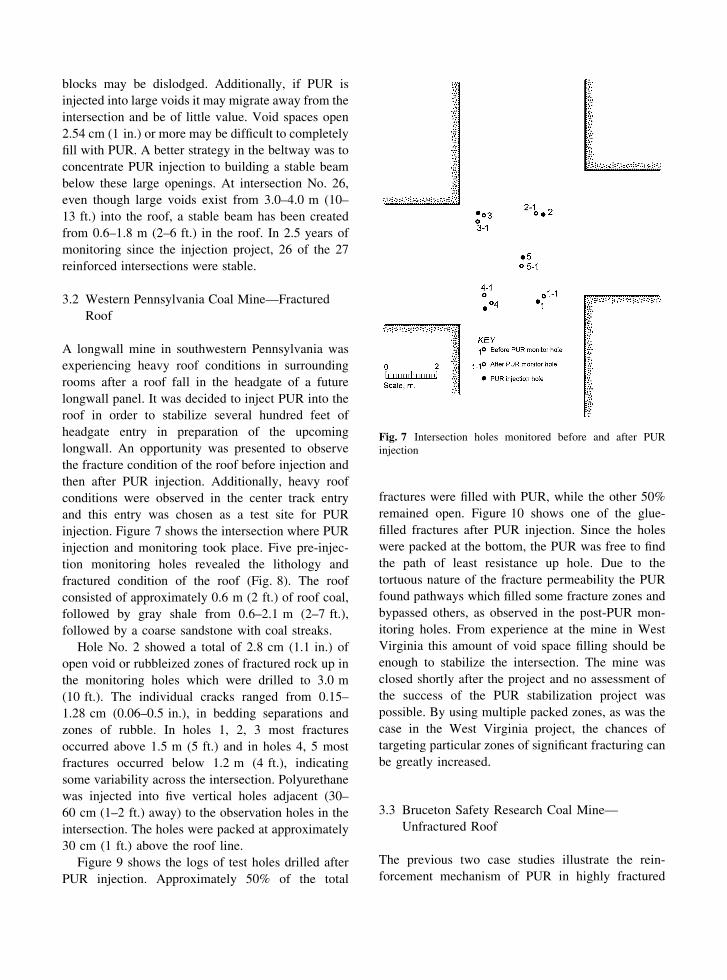
Figure 17 shows the lithology and final location of the
PUR in the immediate roof after the injection in room
C. No open separations occurred in the immediate
3.0 m (10 ft.) of roof rock prior to the injection. In
room C one hole (PH-1) was drilled to 2.4 m (8 ft.),
packed at 1.5 m (5 ft.), and injected with 4.0 l (15 gal)
of PUR (Fig. 15). Then the hole was re-packed at
0.6 m (2 ft.) and injected with another 4.0 l (15 gal) of
PUR. A number of cable and combination bolt holes
experienced leaks as the PUR migrated through the
entry roof. Five monitor holes were videoscoped
after the PUR injection (Fig. 17). The first PUR
injection zone was isolated at 1.5–2.1 m (5–7 ft.). This
was the contact between the sandstone and the
underlying shale. This was done to see if the PUR
could hydrofracture the coarse sandstone with coal
spars. No PUR was observed in the sandstone in any of
the monitoring holes (Fig. 17). It appears that the
bedding in the sandstone was too strong to be
hydrofractured and the PUR must have found some
other conduit for relief. The other injection zone was
isolated at 0.6 m (2 ft.) (PH-1). PUR was injected
from 0.6–1.5 m (2–5 ft.). A thin 0.08–0.64 cm (0.03–
0.25 in.) PUR wafer was observed at 42.7–57.9 cm
Page 11
(1.4–1.9 ft.) up in the roof in two of the video holes
(C-3, 5). These shows were below the packer at 0.6 m
(2 ft.). This indicates that PUR migrated below
the packer and found weak bedding planes at
42.7–57.9 cm (1.4 and 1.9 ft.). Similar to the Bruceton
unfractured roof case, only one zone was hydrofrac
tured and reinforced.
Fig. 15 First recovery
chute with PUR injection
and monitoring holes
Fig. 16 Second recovery
chute with PUR injection
and monitoring holes
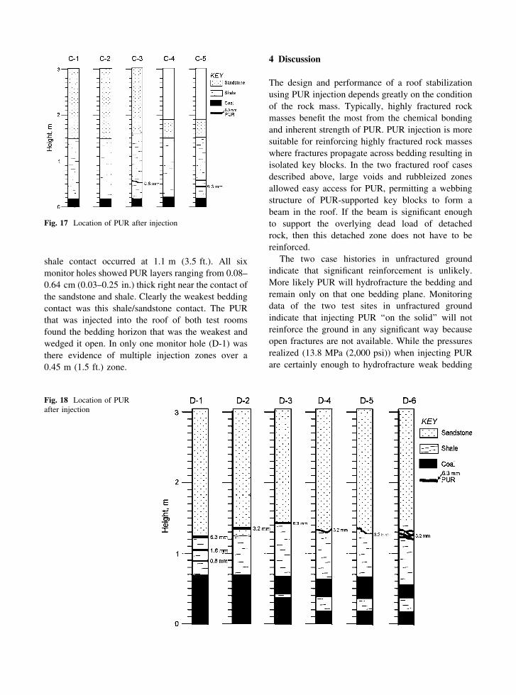
The adjacent chute (D) roof was also injected with
PUR and videomonitored to locate the PUR (Fig. 16).
Injection hole PH-1 was packed at 30 cm (1 ft.) and
pumped with 62.7 l (16.6 gal) of PUR Injection hole
PH-2 was packed at 90 cm (3 ft.) and pumped with
62.7 l (16.6 gal) of PUR. Video monitor holes D-1
thru 6 recorded the results (Fig. 18). The sandstone/
Page 12
shale contact occurred at 1.1 m (3.5 ft.). All six
monitor holes showed PUR layers ranging from 0.08–
0.64 cm (0.03–0.25 in.) thick right near the contact of
the sandstone and shale. Clearly the weakest bedding
contact was this shale/sandstone contact. The PUR
that was injected into the roof of both test rooms
found the bedding horizon that was the weakest and
wedged it open. In only one monitor hole (D-1) was
there evidence of multiple injection zones over a
0.45 m (1.5 ft.) zone.
Fig. 17 Location of PUR after injection
Fig. 18 Location of PUR
after injection
4 Discussion
The design and performance of a roof stabilization
using PUR injection depends greatly on the condition
of the rock mass. Typically, highly fractured rock
masses benefit the most from the chemical bonding
and inherent strength of PUR. PUR injection is more
suitable for reinforcing highly fractured rock masses
where fractures propagate across bedding resulting in
isolated key blocks. In the two fractured roof cases
described above, large voids and rubbleized zones
allowed easy access for PUR, permitting a webbing
structure of PUR-supported key blocks to form a
beam in the roof. If the beam is significant enough
to support the overlying dead load of detached
rock, then this detached zone does not have to be
reinforced.
The two case histories in unfractured ground
indicate that significant reinforcement is unlikely.
More likely PUR will hydrofracture the bedding and
remain only on that one bedding plane. Monitoring
data of the two test sites in unfractured ground
indicate that injecting PUR ‘‘on the solid’’ will not
reinforce the ground in any significant way because
open fractures are not available. While the pressures
realized (13.8 MPa (2,000 psi)) when injecting PUR
are certainly enough to hydrofracture weak bedding
Page 13
planes, the resulting thin layers of PUR do not form a
significant reinforcing web.
The 1.9 cm (0.75 in.) thick layer of polyurethane
injected into the Pittsburgh roof bedding at the
Bruceton site cannot be considered a consistent and
continuous layer, considering the variability of bed
ding strength. The most likely occurrence, seen at
both test sites, is that the PUR will be injected on
only one horizon. Similarly, in the second site at the
longwall recovery chute, only one horizon was
hydrofractured. This single layer cannot be expected
to provide substantial resistance to thick, overlying,
detached roof blocks. These results are consistent
with results obtained by using the hydrofracture
method to measure in situ stress (Enever et al. 1990).
In this procedure, only one bedding fracture is
obtained in weak rock, indicating the path of least
resistance for the fluid. Once the fracture has been
created and the PUR is being injected, large volumes
may be pumped into the single bedding plane
fracture. This additional PUR will provide little
additional reinforcement as it is usually a thin wafer
confined to only one horizon. If substantial rein
forcement is desired in unfractured rock, that goal
must be accomplished by specific design. Multiple
injection zones must be isolated with packers and the
reinforcement will be obtained by the sum of the
strength of several layers of PUR injected into weak
bedding planes.
In reinforcing intersections, current designs utilize
holes drilled in the corner of an entry angled up over
the ribline. The idea is to create a ‘‘grout curtain’’
which could act to contain the polyurethane which
then sets up and forms a barrier over the entry
shoulder. The experience in the unfractured rock
injection in the recovery room shows that this ‘‘over
the-rib grout curtain’’ is unlikely to be successful
because PUR will migrate towards the undermined
entry and not over the solid rib. Additionally, the
polyurethane is thought to resist shearing of roof
layers along the ribline. From the experience in
unfractured rock, a single layer of PUR injected along
bedding is unlikely to provide much resistance to
shearing.
In extremely fractured rock, difficulty was encoun
tered in getting the PUR into the zone targeted for
beam reinforcement. This problem may be addressed
when designing the ‘‘grout curtain’’ to prevent
unwanted PUR loss into voids. This is a barrier
established by injecting PUR around the perimeter of
the intersection, and allowing it to set up before any
subsequent round of PUR injection. Injection holes,
pumping a set volume of PUR, may be drilled in
concentric circles around an intersection, working
towards the center of the intersection. With a 30 s set
time, the PUR will have enough time to form a
barrier before the next injection hole is started. This
method will help to avoid pumping large volumes
into large void spaces.
The study also demonstrated the value of using
video monitoring of fractures prior to PUR injection.
In the West Virginia case, the presence of large open
voids, some as large as 28.2 cm (11 in.) wide,
became the path of least resistance for PUR. Large
volumes of PUR were being pumped into big voids
resulting in wasted resin and little reinforcement.
Video data showed that a reinforced beam from 0.6–
1.8 m (2–6 ft.) could be created which would support
the overlying broken rock. In many intersections
video logs revealed that the roof was extremely
broken up from 0–0.6 m (0–2 ft.) into the roof.
Without this information attempts to inject PUR
under pressure into this zone could result in hazards
from dislodged roof blocks.
5 Conclusions
When using polyurethane injection to stabilize a rock
mass, an understanding of the fracture condition of
the rock mass in advance can help in the design of the
injection. By knowing the location and extent of the
fracture permeability, design parameters; including
volume and expansion properties of chemical grout,
target horizon, and density/geometry of injection
holes, the injection of polyurethane can be optimized.
Pre and post video-monitoring can provide valuable
fracture information for both designing the injection
parameters and evaluating the success of the PUR
stabilization.
In designing a polyurethane stabilization, the goal
should not necessarily be to fill all the fractures in the
roof. Complete void-filling may not be achievable,
except with expanding foam. In extremely fractured
roof, an alternative is a beam-building design where
the goal is to reinforce the fractured rock to the point
where it can support its own weight and the weight of
unconsolidated rock above it. The concept is similar
Page 14
to beam building with roof bolts. If the rock beam can
be maintained intact it can transfer the load of its own
weight to the pillars and act to support the weight of a
limited amount of fractured rock above. Mechani
cally, the polyurethane forms a beam out of rock that
has been separated along bedding or is broken into
key blocks. It is the size and strength of this beam
which determines the stability of the roof.
References
Buddery P (2003) Cost effective use of pur and optimising
large-scale injected strata reinforcement. Report No: 00
180-ACR, ACARP Project C10019, Strata Engineering,
Newcastle, Australia
Enever JR, Wold MB, Crawford GR (1990) Hydraulic frac
turing for rapid low cost stress measurement in
underground mines. AusIMM Bull Proc 295(1):19–24
Jankowski A (1972) Polyurethane for consolidation of rock.
Gluckauf, vol 108, no. 14, pp 582–584
Knoblauch K (1994) Bolting, sealing, consolidation, cavity
filling, repairing: economic and reliable formulas by car
botech. In: Proceedings of the 10th international
conference on coal research, coal: energy for the future,
vol 1, Brisbane, Australia, 9–12 October 1994, pp 417–
435
Micon (2003) Handbook. Polyurethane product specifications.
Available from Micon Products International, 25 Alle
gheny Sq., Glassport, PA 15045-1649
Molinda GM (2004) Evaluation of polyurethane injection for
beltway roof stabilization in a West Virginia coal mine.
In: Proceedings of the 23rd international conference on
ground control in mining, Morgantown, VW, 3–5 August
2004, pp 190–196
Schaller S, Russell P (1986) Trial application of polyurethane
resin in Australian coal mines in ground movement and
control related to coal mining. In: Proceedings of the
symposium on ground movement and control related to
coal mining, Wollongong, Australia, 26 August 1986, pp
134–142
Stewart JG, Hesse M (1985) Roof control with polyurethane
for recovery of Kitt Energy’s 1,000-foot longwall. In:
Proceedings of the 4th conference on ground control in
mining, Morgantown, WV, 22–24 July 1985, pp 78–82