Page 1 Features Application • MV and HV systems with distance or longi- tudinal differential protection as main pro- tection as well as combined in a terminal • Overhead lines, cables and transformer feeders. Distance protection • Overcurrent or underimpedance starters with polygonal characteristic • Five distance zones with polygonal imped- ance characteristic for forwards and reverse measurement • Definite time-overcurrent back-up protec- tion (short-zone protection) • VT supervision • Power swing blocking • System logic - switch-onto-fault - overreach zone • Teleprotection - The carrier-aided schemes include: - permissive underreaching transfer tripping - permissive overreaching transfer tripping - blocking scheme with echo and transient blocking functions • Load-compensated measurement - fixed reactance slope - reactance slope dependent on load value and direction (<Z HV ) • Parallel line compensation • Phase-selective tripping for single and three-pole autoreclosure • Four independent, user-selectable setting groups • Suitable for application with CVTs acc. to IEC 60044. Longitudinal differential protection • Independent measurement per phase • Single-phase tripping (additional FUPLA logic available) • Fast operation (typically 25 ms) • Optical fiber data exchange between termi- nal equipment at 64 kBit/s • Provision for transmitting 8 binary signals, e.g. for direct transfer tripping or blocking • Continuous supervision of protection signal communication • Provision for a power transformer in the zone of protection - phase compensation without interposing CTs - inrush restraint function. Numerical Line Protection REL316*4 1MRK506013-Ben Issued: May 2003 Changed: since February 2002 Data subject to change without notice
Transcript
Page 1
Numerical Line Protection REL316*4
1MRK506013-Ben
Issued: May 2003Changed: since February 2002
Data subject to change without notice
Features Application• MV and HV systems with distance or longi-
tudinal differential protection as main pro-tection as well as combined in a terminal
• Overhead lines, cables and transformer feeders.
Distance protection• Overcurrent or underimpedance starters
with polygonal characteristic
• Five distance zones with polygonal imped-ance characteristic for forwards and reverse measurement
• Optical fiber data exchange between termi-nal equipment at 64 kBit/s
• Provision for transmitting 8 binary signals, e.g. for direct transfer tripping or blocking
• Continuous supervision of protection signal communication
• Provision for a power transformer in the zone of protection- phase compensation without interposing
CTs- inrush restraint function.
Numerical Line Protection REL316*41MRK506013-Ben
Page 2
ABB Switzerland LtdPower Technology Systems
Features (cont’d)Features (cont’d) Earth fault protection• Sensitive earth fault protection for un-
grounded systems and systems with Petersen coils
• Directional comparison function for detect-ing high-resistance faults in neutral earth-ing systems
• Inverse time overcurrent function with four characteristics according to B.S. 142.
Current and voltage functions• Definite time-overcurrent function with in-
rush detection
• Inverse time-overcurrent function with four characteristics according to B.S. 142 and one characteristic identical to the zero-sequence relay type RXIDG
• Directional inverse and definite time over-current protection
• Definite time overvoltage and undervoltage function
• Thermal overload function.
Control and monitoring functions• Single and three-phase multi-shot auto-
reclosure
• Synchrocheck
• Breaker failure protection
• Metering
• Real and apparent power measurement
• 2 different measuring functions of voltage, current and frequency
• Fault location
• Sequence-of-events records
• Disturbance recorder
• Runtime supervision.
Distance protection for high-voltage lines (<ZHV)(Identification code SN100 and SN300)
Application
• 220 kV and 380 kV high-voltage lines in grids with grounded star-points
• Overhead lines and cables.
Distance protection
• All six fault loops are measured simulta-neously (6 systems) allowing the fast detection of evolving faults also in the case of double-circuit lines
• Fast operation, minimum 21 ms and typi-cally 25 ms, see isochrones below
• Suitable for application with CVTs accord-ing to IEC 60044
• Polygonal underimpedance starter with stability against load encroachment
• Distance measurement with polygonal operating characteristic
• Two selectable criteria for the differentia-tion of short circuits with or without earth. Improved detection of the earth fault with application of I2 compared with I0
• The three distance zones responsible for the protection of the line are measured simultaneously and oprate without delay- 1 underreaching zone- 1 overreaching zone for comparison
schemes- 1 reverse measuring zone for compari-
son schemes (echo and tripping logic at weak infeed, stabilization for double li-nes, resp. transmission of the blocking order for blocking systems)
• Load compensation of the reach of the first underreaching distance zone in order to avoid a possible overreach on the load exporting line-side even for high-resistance faults and double-end infeed
• Two time-delayed overreaching back-up zones
• Delayed back-up operation by the under-impedance starter, directional or nondirec-tional
• VT supervision
• Back-up overcurrent function
• The phase selection can be set directional and limited to the effective range of the overreach zone providing improved phase selection for single-pole autoreclosing
Numerical Line Protection REL316*41MRK506013-Ben
Page 3
ABB Switzerland LtdPower Technology Systems
• Elimination of possible overreach in case of resistive phase-to-phase-to-earth faults
• Improved performance under high SIR
• Power swing blocking independent from the operating characteristic and from the place of installation of the distance relay
• System logic and carrier logic:
- automatic switch-onto-fault protection
- overreach zone, effective for all types of fault or for single-phase faults only, con-trolled by the autoreclosure function and current starter via external input or auto-matically in case of failure of the PLC channel
- underreaching permissive transfer trip-ping with or without voltage criterion at weak infeed
- overerreaching permissive transfer trip-ping with echo and tripping logic at weak infeed
- overreaching system with blocking sig-nal
- stabilization of the overreaching sys-tems at change of energy direction on parallel lines
• The distance protection function may be applied for capacitive voltage transformers.
Back-up protection*
• Non-directional overcurrent protection with definite time delay and/or inverse time
• Directional earth fault protection with signal comparison for selective detection of very high-resistance earth faults
• Multi-activation facility of the available function.
* also available in the distance protection function.
Process supervision• Sequence-of-events recorder (with fault
indication)
• Disturbance recorder with analog and binary channels.
Functions for programming by the user• Logic (AND, OR and S/R flip-flop)
• Timer/integrator.
Application-specific ancillary functions(optional)• Graphical engineering of a logic to user
specifications (CAP316). An editor and code compiler are used to generate data, which is loaded into the equipment via the HMI. This software allows signals from all functions to be interconnected and the realization of new functionalities if neces-sary.
Self-supervision• Continuous self-supervision and diagnosis
• Test equipment for quantitative testing available
• Continuous supervision of the optical fiber link for the longitudinal differential function
• Plausibility check of the three-phase cur-rent and voltage inputs.
• Four independent, user-selectable parame-ter sets able to be activated via binary input can be stored in REL316*4
• Multi-activation and allocation of functions.
Serial interfaces• Frontplate interface for local connection of
a personal computer
• Back plane interface for remote communi-cation with a station control system: LON, IEC 60870-5-103, MVB (part of IEC 61375), SPA
• Back plane interface for process bus: MVB (part of IEC 61375).
Installation• REL316*4 is suitable for semi-flush or sur-
face mounting or installation in a rack.
Numerical Line ProtectionABB Switzerland LtdPower Technology Systems
REL316*41MRK506013-Ben
Page 4
Application The fully numerical protection terminal REL316*4 is a compact line terminal. It is designed to provide high-speed selective pro-tection in distribution, MV and HV transmis-sion systems. It can be applied at all power system voltages and in solidly earthed, low-impedance grounded or ungrounded systems or in systems equipped with arc suppression (Petersen) coils.
REL316*4 can be used on overhead lines and cables, long feeders, short feeders, parallel circuit lines, heavily loaded lines, lines with weak infeeds and on ”short zone” lines. It detects all kinds of faults including close three-phase faults, cross-country faults, evolving faults and high-resistance ground faults.
The distance function for high-voltage lines (<ZHV) essentially has identical starting and measuring characteristics.
The differences refer to their speciality for these lines. With regard to their settings this is especially noticeable during phase selection and the adaption to source-to-line impedance conditions. The relay detects evolving faults and follow-up faults. Also at follow-up faults between parallel lines, the probability of suc-cessful single-phase autoreclosure on both systems increases significantly. The reason for this is the limited phase selection within the reach.
Distance and longitudinal differential protec-tion combined in one terminal allows a better protection concept. For example, distance protection as a backup in addition to the tradi-tional overcurrent backup in case of a com-munication failure.
Another application may be longitudinal dif-ferential protection for transformer protection with distance protection as a backup.
REL316*4 also takes account of power swings and changes of energy direction. A switch-onto-fault condition is tripped instan-taneously. The demands on CT and VT per-formance are moderate and the relay’s response is uninfluenced by their charac-teristics.
The distance protection function and the di-rectional comparison function for high-resis-tance earth faults can communicate with the opposite end of the line by all the usual com-munication media as well as by the integrated direct optical connection used for the longitu-dinal differential protection. The communica-tion between the terminals of the phase-seg-ragated longitudinal differential protection can be performed using the integrated or sep-arate optical fiber link.
The promoted solution for 1½ breaker scheme with three-pole tripping and autoreclosing is shown in Fig. 1.- 21 Distance protection: REL316*4 SN100- 87 Line differential protection: REL316*4 SP100- 79/25 Autorecloser/synchrocheck: REL316*4 SD050 or REC316*4.
The promoted solution for 1½ breaker scheme with single-pole tripping and autoreclosing is shown in Fig. 2.- 21 Distance protection: REL316*4 SN100, T141- 87 Line differential protection: REL316*4 SP100, T129- 79/25 Autorecloser/synchrocheck: REL316*4 SD050, T142
or REC316*4, T142.
In these figures two lines are connected to one diameter. Each line is protected by two REL316*4 relays. For the line on the right, the main relay is a distance protection relay (SN100), while the back-up relay is a line dif-ferential relay (SP100). The line on the right is protected with two distance protection re-lays (SN100). The autoreclosure functionality is achieved by one RE.316*4 relay per breaker (e.g. REL316*4 SD050).
For a single-pole application, the distance protection relay (SN100) is loaded with the supplementary FUPLA logic T141, the line differential relay (SP100) with the logic T129 and the autorecloser (e.g. SD050) with the logic T142.
The autoreclosure functions used for the bus breakers A and C are set as Masters and the one for the centre breaker B as Follower. Co-ordination is required between the autorec-losure functions. A synchrocheck function is also loaded in each relay to permit 3-pole autoreclosing.
Each line protection relay starts both bus and centre breakers for the concerned line. After a successful reclosure of the bus breaker, the centre breaker will be reclosed after a supple-mentary time delay. Should the bus CB autorecloser relay not be successful in its reclosing attempt, the centre CB autorecloser is blocked. If the bus CB is open or its autore-closer relay is not ready or out of service, the centre CB autorecloser will reclose the centre breaker after its own dead time without any supplementary time delay.
79 (AR)25 (sync)RE.316*4
T142
79 (AR)25 (sync)RE.316*4
T142
79 (AR)25 (sync)RE.316*4
T142
21 (dist.)REL316*4
SN100,T141
87 (line diff.)REL316*4
SP100,T129
21 (dist.)REL316*4
SN100,T141
21 (dist.)REL316*4
SN100,T141
TRIP TRIPTRIP TRIP TRIP TRIPTRIP TRIP
A B C
Numerical Line ProtectionABB Switzerland LtdPower Technology Systems
REL316*41MRK506013-Ben
Page 6
Design The REL316*4 belongs to the generation of fully numerical line protection terminals, i.e. analog-to-digital conversion of the input vari-ables takes place immediately after the input transformers and all further processing of the resulting numerical signals is performed by microprocessors and controlled by programs.
Standard interfaces enable REL316*4 to communicate with other control systems. Provision is thus made for the exchange of data such as reactionless reporting of binary states, events, measurements and protection parameters or the activation of a different set of settings by higher level control systems.
Because of its compact design, the very few hardware units it needs, its modular software and the integrated continuous self-diagnosis and supervision functions, REL316*4 ideally fulfils the user’s expectations of a modern protection terminal at a cost-effective price. The AVAILABILITY of a terminal, i.e. the ratio between its mean operating time in ser-vice without failure and its total life, is most
certainly the most important characteristic re-quired of protection equipment. As a conse-quence of the continuous supervision of its functions, this quotient in the case of REL316*4 is typically always close to 1.
The menu-based HMI (Human Machine Interface) and the REL316*4’s small size makes the tasks of connection, configuration and setting simple. A maximum of FLEXI-BILITY, i.e. the ability to adapt the protection for application in a particular power system or to coordinate with, or replace units in an existing protection scheme, is provided in REL316*4 by ancillary software functions and the assignment of input and output sig-nals via the HMI.
REL316*4’s RELIABILITY, SELECTIVITY and STABILITY are backed by decades of experience in the protection of lines and feed-ers in transmission and distribution systems. Numerical processing ensures consistent ACCURACY and SENSITIVITY throughout its operational life.
Hardware The hardware concept for the REL316*4 line protection equipment comprises four differ-ent plug-in units, a connecting mother PCB and housing (Fig. 3):
• analog input unit• central processing unit• 1 to 4 binary input/output units• power supply unit• connecting mother PCB• housing with connection terminals.
In the analog input unit an input transformer provides the electrical and static isolation between the analog input variables and the internal electronic circuits and adjusts the sig-nals to a suitable level for processing. The
input transformer unit can accommodate a maximum of nine input transformers (volt-age-, protection current- or measuring trans-former).
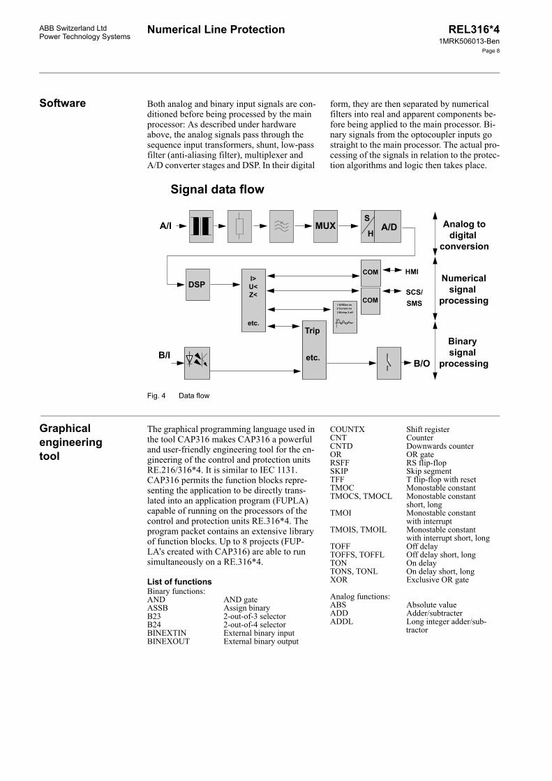
Every analog variable is passed through a first order R/C low-pass filter on the main CPU unit to eliminate what is referred to as the aliasing effect and to suppress HF inter-ferences (Fig. 4). They are then sampled 12 times per period and converted to digital sig-nals. The analog/digital conversion is per-formed by a 16 Bit converter.
A powerful digital signal processor (DSP) carries out part of the digital filtering and makes sure that the data for the protection algorithms are available in the memory to the main processor.
Numerical Line Protection REL316*41MRK506013-Ben
Page 7
ABB Switzerland LtdPower Technology Systems
Fig. 3 Hardware platform overview (RE.316*4)
The processor core essentially comprises the main microprocessor (Intel 80486) for the protection algorithms and dual-ported memo-ries (DPMs) for communication between the A/D converters and the main processor. The main processor performs the protection algo-rithms and controls the local HMI and the in-terfaces to the station control system. Binary signals from the main processor are relayed to the corresponding inputs of the I/O unit and thus control the auxiliary output relays and the light emitting diode (LED) signals. The main processor unit is equipped with an RS232C serial interface via which among other things the protection settings are made, events are read and the data from the distur-bance recorder memory are transferred to a local or remote PC.
On this main processor unit there are two PCC slots and one RS232C interface. These serial interfaces provide remote communica-tion to the station monitoring system (SMS) and station automation system (SAS) as well as to the remote I/Os.
REL316*4 can have one to four binary I/O units each. These units are available in three versions:
a) two tripping relays with two heavy-duty contacts, 8 optocoupler inputs and 6 signalling relays Type 316DB61.
b) two tripping relays with two heavy-duty contacts, 4 optocoupler inputs and 10 sig-nalling relays Type 316DB62.
c) 14 optocoupler inputs and 8 signalling relays Type 316DB63.
When ordering REL316*4 with more than 2 I/O units, casing size N2 must be selected.
According to whether one or two I/O units are fitted, there are either 8 LEDs or 16 LEDs visible on the front of the REL316*4.
Fibre optical connections for line differentialprotection and binary signal transmission
HMI
TripOutputs
Sign.Outputs
Bin.Inputs
Remote I/O
PCMCIA
a
b
c
d
DC
DC+5V
+15V
-15V+24V
PowerSupply
A/D DSP
CPU486
SerialController
RS232
FLASHEPROM
Tranceiver
RAM
SW-Key
PCC
LONIEC1375
SPA / IEC870-5-103
LED'sSCSSMS
SerialController
RS232
DPM
TripOutputs
Sign.Outputs
Bin.Inputs
I / OPorts
PCC
Process bus
TripOutputs
Sign.Outputs
Bin.Inputs
Remote I/O
TripOutputs
Sign.Outputs
Bin.Inputs
Remote I/O
TripOutputs
Sign.Outputs
Bin.Inputs
I / OPorts
TripOutputs
Sign.Outputs
Bin.Inputs
I / OPorts
TripOutputs
Sign.Outputs
Bin.Inputs
I / OPorts (MVB)
RX Tx
A/D DSP
IEC1375
Numerical Line ProtectionABB Switzerland LtdPower Technology Systems
REL316*41MRK506013-Ben
Page 8
Software Both analog and binary input signals are con-ditioned before being processed by the main processor: As described under hardware above, the analog signals pass through the sequence input transformers, shunt, low-pass filter (anti-aliasing filter), multiplexer and A/D converter stages and DSP. In their digital
form, they are then separated by numerical filters into real and apparent components be-fore being applied to the main processor. Bi-nary signals from the optocoupler inputs go straight to the main processor. The actual pro-cessing of the signals in relation to the protec-tion algorithms and logic then takes place.
Fig. 4 Data flow
Graphical engineering tool
The graphical programming language used in the tool CAP316 makes CAP316 a powerful and user-friendly engineering tool for the en-gineering of the control and protection units RE.216/316*4. It is similar to IEC 1131. CAP316 permits the function blocks repre-senting the application to be directly trans-lated into an application program (FUPLA) capable of running on the processors of the control and protection units RE.316*4. The program packet contains an extensive library of function blocks. Up to 8 projects (FUP-LA’s created with CAP316) are able to run simultaneously on a RE.316*4.
List of functionsBinary functions:AND AND gateASSB Assign binaryB23 2-out-of-3 selectorB24 2-out-of-4 selectorBINEXTIN External binary inputBINEXOUT External binary output
COUNTX Shift registerCNT CounterCNTD Downwards counterOR OR gateRSFF RS flip-flopSKIP Skip segmentTFF T flip-flop with resetTMOC Monostable constantTMOCS, TMOCL Monostable constant
short, long TMOI Monostable constant
with interruptTMOIS, TMOIL Monostable constant
with interrupt short, longTOFF Off delayTOFFS, TOFFL Off delay short, longTON On delayTONS, TONL On delay short, longXOR Exclusive OR gate
Analog functions:ABS Absolute valueADD Adder/subtracterADDL Long integer adder/sub-
tractor
Numerical Line Protection REL316*41MRK506013-Ben
Page 9
ABB Switzerland LtdPower Technology Systems
ADMUL Adder/multiplierCNVIL Integer to long integer
converterCNVLBCD Long integer to BC con-
verterCNVLI Long integer to integer
converterCNVLP Long integer to percent
converterCNVPL Percentage to long inte-
ger converterDIV DividerDIVL Long integer dividerFCTL Linear functionFCTP Polynomial functionFILT FilterINTS, INTL IntegratorKMUL Factor multiplier
LIM LimiterLOADS Load shedding functionMAX Maximum value detectorMIN Minimum value detectorMUL MultiplierMULL Long integer multiplierNEGP Percent negatorPACW Pack binary signals
Part of a FUPLA application (Q0: Control and interlocking logic for three objectsQ0, Q1, Q2. B_DRIVE is a macro composed of binary function blocks)
DPMIN_Q0_CLOSEDDPMIN_Q0_OPEN
Q0_SEL_DRIVE_Q0GEN_REQUEST_ON
GEN_REQUES_ON
GEN_SYNCQ1_Q1_OPENQ2_Q2_OPEN
GEN_REQUEST_EXE
B_DRIVECLOP
SELRQONRQOF
SYNCRQEX
T:SYT:RT
CLOP
POK
GONGOFGEXEXE
GOONGOOFSYSTSREL
ALSYBKS
KDOF
Q0_CLQ0_OPQ0_Q0_POK
Q0_Q0_CLOSED
Q0_Q0_OPEN
Q0_GUIDE_ONQ0_GUIDE_OFFQ0_GUIDE_EXEQ0_EXE
Q0_GOON_Q0Q0_GOOFF_Q0Q0_Q0_SYSTDPMOUT_Q0_SEL_REL
Q0_SUP_SEL_REL_Q0
Q0_ALSYQ0_BLOCK_SELECTQ0_KDO_FAIL
1&
2>=1
6=1
5&
4&
3
301
Numerical Line ProtectionABB Switzerland LtdPower Technology Systems
REL316*41MRK506013-Ben
Page 10
Functions The library of function modules for REL316*4 includes a variety of protection and ancillary functions from which the user can choose according to relay version (see ”Ordering data”). Within the constraints of the available processing capacity, the same function may be included several times. Four parameter sets may be selected via binary in-puts. The individual functions are described below.
Distance protectionThe distance protection function can have either overcurrent or underimpedance start-ers. They are equally suitable for use in sol-idly grounded, ungrounded or impedance grounded systems. In the case of ungrounded and impedance grounded systems, all the relays in the system have to have identically set phase-preference logics to maintain selec-tivity for cross-country faults. The following phase-preference schemes are available:
RTS acyclic (R before T before S)RST acyclic (R before S before T)TSR acyclic (T before S before R)TRS acyclic (T before R before S)SRT acyclic (S before R before T)STR acyclic (S before T before R)RTSR cyclic (R bef. T, T bef. S, S bef. R)TRST cyclic (T bef. R, R bef. S, S bef. T).
The relay detects ground faults on the basis of the neutral current and/or neutral voltage.
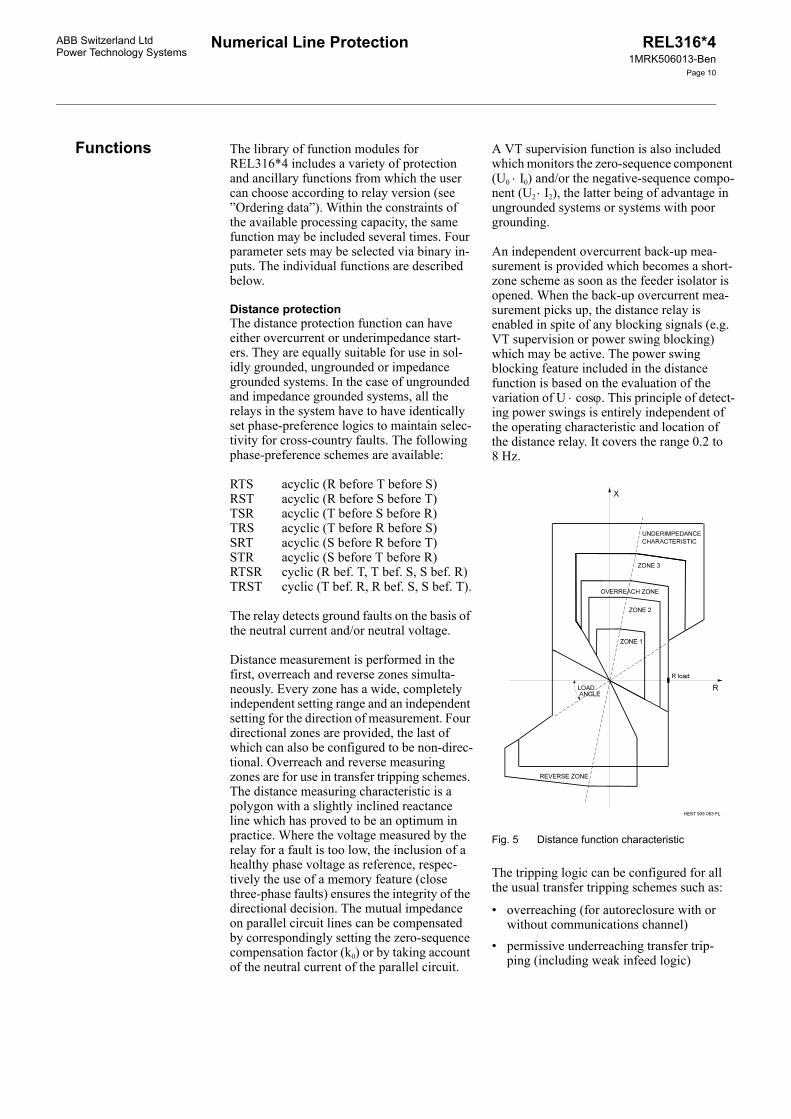
Distance measurement is performed in the first, overreach and reverse zones simulta-neously. Every zone has a wide, completely independent setting range and an independent setting for the direction of measurement. Four directional zones are provided, the last of which can also be configured to be non-direc-tional. Overreach and reverse measuring zones are for use in transfer tripping schemes. The distance measuring characteristic is a polygon with a slightly inclined reactance line which has proved to be an optimum in practice. Where the voltage measured by the relay for a fault is too low, the inclusion of a healthy phase voltage as reference, respec-tively the use of a memory feature (close three-phase faults) ensures the integrity of the directional decision. The mutual impedance on parallel circuit lines can be compensated by correspondingly setting the zero-sequence compensation factor (k0) or by taking account of the neutral current of the parallel circuit.
A VT supervision function is also included which monitors the zero-sequence component (U0 ⋅ I0) and/or the negative-sequence compo-nent (U2 ⋅ I2), the latter being of advantage in ungrounded systems or systems with poorgrounding.
An independent overcurrent back-up mea-surement is provided which becomes a short-zone scheme as soon as the feeder isolator is opened. When the back-up overcurrent mea-surement picks up, the distance relay is enabled in spite of any blocking signals (e.g. VT supervision or power swing blocking) which may be active. The power swing blocking feature included in the distance function is based on the evaluation of the variation of U ⋅ cosϕ. This principle of detect-ing power swings is entirely independent of the operating characteristic and location of the distance relay. It covers the range 0.2 to 8 Hz.
Fig. 5 Distance function characteristic
The tripping logic can be configured for all the usual transfer tripping schemes such as:
• overreaching (for autoreclosure with or without communications channel)
• permissive underreaching transfer trip-ping (including weak infeed logic)
Numerical Line Protection REL316*41MRK506013-Ben
Page 11
ABB Switzerland LtdPower Technology Systems
• permissive overreaching transfer tripping (with echo tripping in the case of a weak-infeed and blocking logic for change of energy direction)
• blocking scheme (with blocking logic for change of energy direction).
The tripping logic provides access for the user to disable or enable a variety of func-tions such as the type communications chan-nel, the switch-onto-fault logic, the over-reaching zone, the VT supervision logic and whether tripping by the function should be single or three-phase.
Distance protection for high-voltage linesThe distance protection function (<ZHV) is especially suited for 220 kV and 380 kV lines.
The "HV distance" function essentially has identical starting and measuring characteris-tics and the same setting parameters as the standard "distance" function.
The setting parameters for not effectively earthed networks have been omitted and a few new ones added, especially in connection with an improved phase selection.
The operating times for the "HV distance" function are shown in the form of isochrones. (see Section 'High-voltage distance protec-tion function operating times'). All other functions remain unchanged.
Longitudinal differential protectionThe longitudinal differential protection func-tion included with REL316*4 is suitable for the protection of
• overhead lines• cables• transformer feeders.It operates according to the proven trans-former protection algorithm used in RET316*4 and exhibits the same outstanding characteristics with respect to through-fault stability and minimum CT performance.
The scheme is phase-selective and takes full advantage of the high data transfer rate of 64 kBit/s possible with an optical fiber link to sample the analog input variables at both ends of the line and transfers the correspond-ing values to the opposite station without al-most any delay.
Fig. 6 Operating characteristic of the longitudinal differential function
I2
Numerical Line Protection REL316*41MRK506013-Ben
Page 12
ABB Switzerland LtdPower Technology Systems
Functions (cont’d)Functions (cont’d)
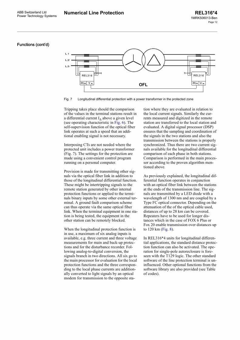
Fig. 7 Longitudinal differential protection with a power transformer in the protected zone
Tripping takes place should the comparison of the values in the terminal stations result in a differential current I∆ above a given level (see operating characteristic in Fig. 6). The self-supervision function of the optical fiber link operates at such a speed that an addi-tional enabling signal is not necessary.
Interposing CTs are not needed where the protected unit includes a power transformer (Fig. 7). The settings for the protection are made using a convenient control program running on a personal computer.
Provision is made for transmitting other sig-nals via the optical fiber link in addition to those of the longitudinal differential function. These might be intertripping signals to the remote station generated by other internal protection functions or applied to the termi-nals binary inputs by some other external ter-minal. A ground fault comparison scheme can thus operate via the same optical fiber link. When the terminal equipment in one sta-tion is being tested, the equipment in the other station can be remotely blocked.
When the longitudinal protection function is in use, a maximum of six analog inputs is available, e.g. three current and three voltage measurements for main and back-up protec-tions and for the disturbance recorder. Fol-lowing analog-to-digital conversion, the signals branch in two directions. All six go to the main processor for evaluation for the local protection functions and the three correspon-ding to the local phase currents are addition-ally converted to light signals by an optical modem for transmission to the opposite sta-
tion where they are evaluated in relation to the local current signals. Similarly the cur-rents measured and digitized in the remote station are transferred to the local station and evaluated. A digital signal processor (DSP) ensures that the sampling and coordination of the signals in the two stations and also the transmission between the stations is properly synchronized. Thus there are two current sig-nals available for the longitudinal differential comparison of each phase in both stations. Comparison is performed in the main proces-sor according to the proven algorithm men-tioned above.
As previously explained, the longitudinal dif-ferential function operates in conjunction with an optical fiber link between the stations at the ends of the transmission line. The sig-nals are transmitted by a LED diode with a wavelength of 1300 nm and are coupled by a Type FC optical connector. Depending on the attenuation of the of the optical cable used, distances of up to 28 km can be covered. Repeaters have to be used for longer dis-tances which in the case of FOX 6 Plus or Fox 20 enable transmission over distances up to 120 km (Fig. 8).
In REL316*4 units for longitudinal differen-tial applications, the standard distance protec-tion function can also be activated. The ope-ration for single-pole autoreclosure is fore-seen with the T129 logic. The other standard software of the line protection terminal is un-influenced. Other optional functions from the software library are also provided (see Table of codes).
OFL
Numerical Line ProtectionABB Switzerland LtdPower Technology Systems
REL316*41MRK506013-Ben
Page 13
Fig. 8 Optical fiber link (OFL) using communications system Type FOX with a data transfer rate of 2 MBit/s
AutoreclosureThe autoreclosure function included in REL316*4 permits up to four three-phase reclosure cycles to be carried out, each with an independently adjustable dead time for fast and slow autoreclosure. Where single-phase reclosure is being applied, the first reclosure is the single-phase one and the others are three-phase.
The autoreclosure function can also be loaded several times in the same parameter set. This function also contains an integrated additio-nal logic (FUPLA). This allows a customer-specific AR functionality. Both these possi-bilities have been used for the CH standard AR. Two AR functions are loaded for this: the first function with additional logic serves as fast autoreclosure and the second function as slow autoreclosure.
The integrated autoreclosure function for high-voltage lines (REL316*4/SN300) is employed on lines without local protection redundancy.
A separate autoreclosure unit is especially suitable for lines with redundant protection.
This unit enables practically all conventional and all modern line protection relays suitable for single-phase tripping to be connected to one system.
SynchrocheckThe synchrocheck function determines the difference between the amplitudes, phase angles and frequencies of two voltage vec-tors. Checks are also included to detect a dead line or busbar.
Thermal overloadThe thermal overload function can be used for either cables or overhead lines. It is equip-ped with alarm and tripping stages and has a wide setting range for adjusting the time con-stant to match that of the protected unit.
Definite time voltage functionThe voltage function can be set to operate on overvoltage or undervoltage with a definite time delay. Either single or three-phase mea-surements can be performed.
Definite time current functionThe current function can be set to operate on overcurrent or undercurrent with a definite time delay. Either single or three-phase mea-surements can be performed.
Inverse time overcurrent functionThe operating time of the inverse time over-current function reduces as the fault current increases and it can therefore achieve shorter operating times for fault locations closer to the source. Four different characteristics ac-cording to British Standard 142 designated normal inverse, very inverse, extremely in-verse and long time inverse but with an ex-tended setting range are provided. The func-tion can be configured for single-phase mea-
Numerical Line Protection REL316*41MRK506013-Ben
Page 14
ABB Switzerland LtdPower Technology Systems
Functions (cont’d)Functions (cont’d) surement or a combined three-phase mea-surement with detection of the highest phase current.
Directional overcurrent protectionThe directional overcurrent protection func-tion is available either with inverse time or definite time overcurrent characteristic. This function comprises a voltage memory for faults close to the relay location. The function response after the memory time has elapsed can be selected (trip or block).
Inverse time ground fault overcurrent functionThe inverse time ground fault overcurrent function monitors the neutral current of the system which is either measured via a neutral current input transformer or derived inter-nally in the terminal from the three-phase cur-rents. Four different characteristics according to British Standard 142 designated normal inverse, very inverse, extremely inverse and long time inverse but with an extended set-ting range are provided.
Directional ground fault function for ungrounded systems or systems with Petersen coilsThe sensitive ground fault protection function for ungrounded systems and systems with Petersen coils can be set for either forwards or reverse measurement. The characteristic angle is set to ±90° (U0 • I0 • sinϕ) in ungroun-ded systems and to 0° or 180° (U0 • I0 • cosϕ) for systems with Petersen coils. The neutral current is always used for measurement in the case of systems with Petersen coils, but in ungrounded systems its use is determined by the value of the capacitive current and mea-surement is performed by a core-balance CT to achieve the required sensitivity.
Directional ground fault function for grounded systemsA sensitive directional ground fault function based on the measurement of neutral current and voltage is provided for the detection of high-resistance ground faults in solidly or low-resistance grounded systems. The scheme operates either in a permissive or blocking mode and can be used in conjunc-tion with an inverse time ground fault over-current function. In both cases the neutral current and voltage can be derived either externally or internally.
Frequency functionThe frequency function is based on the mea-surement of one voltage. This function is able to be configured as maximum or minimum function and is applied as protection function and for load shedding. By multiple configura-tion of this function almost any number of stages can be realized.
Rate-of-change of frequency This function offers alternatively an enabling by absolute frequency. It contains an under-voltage blocking facility. Repeated configura-tion of this function ensures a multi-step setup.
MeasuringBoth measuring functions measure the single-phase rms values of voltage, current, frequen-cy, real power and apparent power for display on the local HMI or transfer to the station control system. A choice can be made bet-ween phase-to-neutral and phase-to-phase voltages.
Ancillary functionsAncillary functions such as a logic and a de-lay/integrator enable the user to create logical combinations of signals and pick-up and reset delays.
A runtime supervision feature enables check-ing the opening and closing of all kinds of breakers (circuit-breakers, isolators, ground switches...). Failure of a breaker to open or close within an adjustable time results in the creation of a corresponding signal for further processing.
Plausibility checkThe current and voltage plausibility functions facilitate the detection of system asymme-tries, e.g. in the secondary circuits of CTs and VTs.
Sequence-of-events recorderThe event recorder function provides capacity for up to 256 binary signals including time marker with a resolution in the order of milli-seconds and gives the distance to a fault ex-pressed as a percentage of a specified refer-ence reactance, e.g. the reactance of the pro-tected line.
Disturbance recorderThe disturbance recorder monitors up to 9 analog inputs, up to 16 binary inputs and internal results of protection functions. The capacity for recording disturbances depends on the duration of a disturbance as deter-
Numerical Line ProtectionABB Switzerland LtdPower Technology Systems
REL316*41MRK506013-Ben
Page 15
mined by its pre-disturbance history and the duration of the disturbance itself. The total recording time is approximately 5 s.
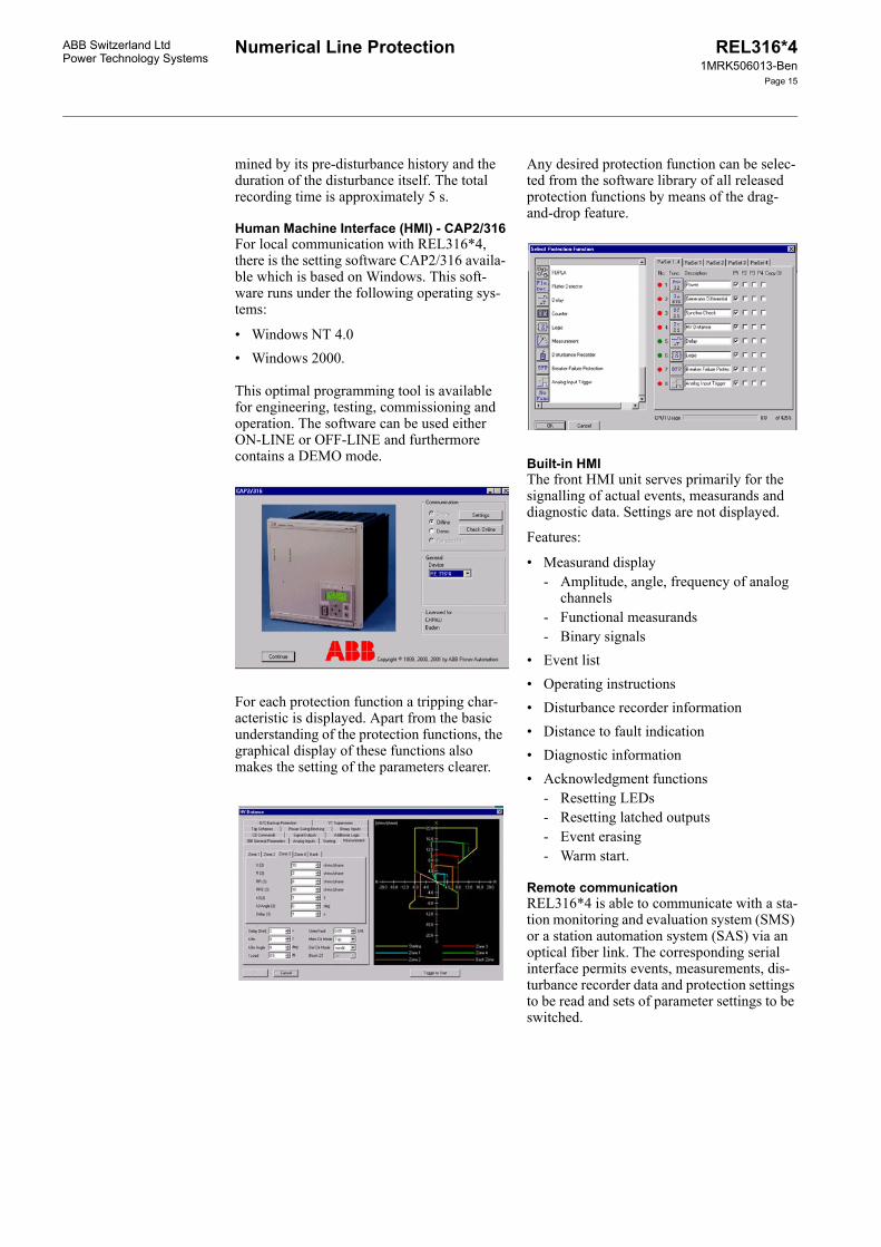
Human Machine Interface (HMI) - CAP2/316For local communication with REL316*4, there is the setting software CAP2/316 availa-ble which is based on Windows. This soft-ware runs under the following operating sys-tems:
• Windows NT 4.0• Windows 2000.
This optimal programming tool is available for engineering, testing, commissioning and operation. The software can be used either ON-LINE or OFF-LINE and furthermore contains a DEMO mode.
For each protection function a tripping char-acteristic is displayed. Apart from the basic understanding of the protection functions, the graphical display of these functions also makes the setting of the parameters clearer.
Any desired protection function can be selec-ted from the software library of all released protection functions by means of the drag-and-drop feature.
Built-in HMIThe front HMI unit serves primarily for the signalling of actual events, measurands and diagnostic data. Settings are not displayed.
Features:
• Measurand display- Amplitude, angle, frequency of analog
Remote communicationREL316*4 is able to communicate with a sta-tion monitoring and evaluation system (SMS) or a station automation system (SAS) via an optical fiber link. The corresponding serial interface permits events, measurements, dis-turbance recorder data and protection settings to be read and sets of parameter settings to be switched.
Numerical Line Protection REL316*41MRK506013-Ben
Page 16
ABB Switzerland LtdPower Technology Systems
Functions (cont’d)Functions (cont’d) Using the LON bus permits in addition the exchange of binary information between the individual bay controllers, e.g. signals for sta-tion interlocking.
Remote in- and outputs (RIO580)Using the process bus type MVB remote in- and output units (500RIO11) can be connec-ted to the RE.316*4 terminals. The input and output channels can be extended to a large number by using the RIO580 remote input/output system. Installing 500RIO11 I/O close to the process reduces the wiring dramati-cally, since they are accessible via fiberoptic link from the RE.316*4 terminals.
Analog signals can also be connected to the system via the 500AXM11 from the RIO580 family:
Self-diagnosis and supervisionRE.316*4’s self-diagnosis and supervision functions ensure maximum availability not only of the protection terminal itself, but also of the power system it is protecting. Hard-ware failures are immediately signalled by an alarm contact. In particular, the external and internal auxiliary supplies are continuously supervised. The correct function and toler-ance of the A/D converter are tested by cycli-cally converting two reference voltages. Spe-cial algorithms regularly check the proces-sor’s memories (background functions). A watchdog supervises the execution of the pro-grams.
The program execution itself is monitored by a watchdog function for each processor.
An important advantage of the extensive self-diagnosis and supervision functions is that periodic routine maintenance and testing are reduced.
The optical fiber link is also supervised on terminal equipped with the longitudinal dif-ferential function. For this purpose test data are transmitted in addition to the protection signals to test the integrity of the communica-tions channel. The supervision function also detects the failure of the auxiliary supply in one terminal station. In the event that the optical fiber link should fail, the back-up pro-tection functions remain operational.
Supporting softwareThe operator program facilitates configura-tion and setting of the protection, listing para-meters, reading events and listing the various internal diagnostic data.
The evaluation programs REVAL and E_wineve (Windows NT/Windows 2000) are available for viewing and evaluating the dis-turbances stored by the disturbance recorder. Where the disturbance data are transferred via the communications system to the distur-bance recorder evaluation station, the file transfer program WinCom (Windows NT/Windows 2000) is also used.
The program XSCON is available for conver-sion of the RE.316*4 disturbance recorder data to ABB’s test set XS92b format. This offers reproduction of electrical quantities recorded during a fault.
Numerical Line ProtectionABB Switzerland LtdPower Technology Systems
REL316*41MRK506013-Ben
Page 17
Technical datahardware
Table 1: Analog input variables
Table 2: Contact data
Number of inputs according to version, max. 9 analog inputs (voltages and currents, 4 mm2 terminals)
Rated frequency fN 50 Hz or 60 Hz
Rated current IN 1 A, 2 A or 5 A
Thermal rating of current circuitcontinuousfor 10 sfor 1 sdynamic (half period)
4 x IN30 x IN100 x IN250 x IN (peak)
Rated voltage UN 100 V or 200 V
Thermal rating of voltage circuitcontinuousduring 10 s
1.3 x UN2 x UN
Burden per phasecurrent inputs
at IN = 1 Aat IN = 5 A
voltage inputsat UN
<0.1 VA<0.3 VA
<0.25 VA
VT fuse characteristic Z acc. to DIN/VDE 0660 or equivalent
Tripping relays
No. of contacts 2 relays per I/O unit 316DB61 or 316DB62 with 2 N/O contacts each, 1.5 mm2 terminals
Max. operating voltage 300 V AC or V DC
Continuous rating 5 A
Make and carry for 0.5 s 30 A
Surge for 30 ms 250 A
Making power at 110 V DC 3300 W
Breaking capacity for L/R = 40 msBreaking current with 1 contact
at U <50 V DCat U <120 V DCat U <250 V DC
1.5 A0.3 A0.1 A
Breaking current with 2 contacts in seriesat U <50 V DCat U <120 V DCat U <250 V DC
5 A1 A0.3 A
Signalling contacts
No. of contacts 6, 10 or 8 acc. to I/O unit (316DB61, 316DB62 or 316DB63),1 contact per sig. relay with 1.5 mm2 terminalsEach interface unit equipped with 1 C/O contact and the all others N/O contacts
Max. operating voltage 250 V AC or V DC
Continuous rating 5 A
Make and carry for 0.5 s 15 A
Surge for 30 ms 100 A
Making power at 110 V DC 550 W
Breaking current for L/R = 40 ms at U <50 V DCat U <120 V DCat U <250 V DC
0.5 A0.1 A0.04 A
The user can assign tripping and signalling contacts to protection functions
Numerical Line Protection REL316*41MRK506013-Ben
Page 18
ABB Switzerland LtdPower Technology Systems
Technical data hard-ware (cont’d)Technical data hard-ware (cont’d)
Table 3: Optocoupler inputs
Table 4: Light-emitting diodes
Table 5: Configuration and settings
Table 6: Remote communication
No. of optocouplers 8, 4 or 14 acc. to I/O unit(316DB61, 316DB62 or 316DB63)
Input voltage 18 to 36 V DC / 36 to 75 V DC / 82 to 312 V DC /175 to 312 V DC
Threshold voltage 10 to 17 V DC / 20 to 34 V DC / 40 to 65 V DC / 140 to 175 V DC
Max. input current <12 mA
Operating time 1 ms
The user can assign the inputs to protection functions.
Choice of display modes:
• Accumulates each new disturbance• Latching with reset by next pick-up• Latching only if protection trips with reset by next pick-up• Signalling without latching
Colors 1 green (standby)1 red (trip)6 or 14 yellow (all other signals)
The user can assign the LEDs to protection functions.
Local via the communication interface on the front port connector using an IBM-compatible PC with Win-dows NT 4.0 or Windows 2000. The operator program can also be operated by remote control via a modem.
Operator program in English or German
RS232C interfaceData transfer rateProtocolElectrical/optical converter (optional)
9 pin Sub-D female9600 Bit/sSPA or IEC 60870-5-103316BM61b
PCC interfaceNumber 2 plug-in sockets for type III cards
PCC (optional)Interbay bus protocolProcess bus protocol(interbay and process bus can be used concurrently)
LON busData transfer rate
LON or MVB (part of IEC 61375)MVB (part of IEC 61375)
PCC with fiber-optical port, ST connectors1.25 MBit/s
MVB bus
Data transfer rate
PCC with redundant fiber-optical port, ST connectors1.5 Mbit/s
Event memoryCapacityTime marker resolution
256 events1 ms
Time deviation without remote synchronizing <10 s per day
Engineering interface integrated software interface for signal engi-neering with SigTOOL
Numerical Line ProtectionABB Switzerland LtdPower Technology Systems
REL316*41MRK506013-Ben
Page 19
Table 7: Auxiliary supply
Table 8: General data
Supply voltage
Voltage range 36 to 312 V DC
Voltage interruption bridging time >50 ms
Fuse rating ≥4 A
Load on station battery at normal operation(1 relay energized) <20 W
during a fault (all relays energized)
with 1 I/O unitwith 2 I/O unitswith 3 I/O unitswith 4 I/O units
<22 W<27 W<32 W<37 W
Additional load of the optionsline differential protection (code SPxxx)SPA, IEC 60870-5-103 or LON interfaceMVB interface
7.5 W1.5 W2.5 W
Buffer time of the event list and fault recorder data at loss of auxiliary supply >2 days (typ. 1 month)
Temperature rangeoperationstorage
-10°C to +55°C-40°C to +85°C
EN 60255-6 (1994),IEC 60255-6 (1988)
Humidity 93%, 40°C, 4 days IEC 60068-2-3 (1969)
Seismic test 5 g, 30 s, 1 to 33 Hz (1 octave/min)
IEC 60255-21-3 (1995),IEEE 344 (1987)
Leakage resistance >100 MΩ, 500 V DC EN 60255-5 (2001),IEC 60255-5 (2000)
Insulation test 2 kV, 50 Hz, 1 min1 kV across open contacts
EN 60255-5 (2001),IEC 60255-5 (2000),EN 60950 (1995)
Surge voltage test 5 kV, 1.2/50 µs EN 60255-5 (2001),IEC 60255-5 (2000) *
Emission Cl. A EN 61000-6-2 (2001),EN 55011 (1998),CISPR 11 (1990)
* Reduced values apply for repeat tests according to IEC publication 255-5, Clauses 6.6 and 8.6.
Numerical Line Protection REL316*41MRK506013-Ben
Page 20
ABB Switzerland LtdPower Technology Systems
Technical data hard-ware (cont’d)Technical data hard-ware (cont’d)
Table 9: Mechanical designWeight
Size N1 casingSize N2 casing
approx. 10 kgapprox. 12 kg
Methods of mounting semi-flush with terminals at rearsurface with terminals at rear19" rack mounting, height 6U, width N1: 225.2 mm (1/2 19" rack). Width N2: 271 mm.
Enclosure Protection Class
IP 50 (IP 20 if MVB PC cards are used)IPXXB for terminals.
Numerical Line ProtectionABB Switzerland LtdPower Technology Systems
REL316*41MRK506013-Ben
Page 21
Technical datafunctions
Table 10: Distance and high-voltage distance protection (21)All values of settings referred to the secondaries, every zone can be set independently of the others,4 independent files for sets of settings.
Impedance measurement -300 to 300 Ω/ph in steps of 0.01 Ω/ph (IN = 1 A or 2 A)-30 to 30 Ω/ph in steps of 0.001 Ω/ph (IN = 5 A)
Zero-sequence current compensation 0 to 8 in steps of 0.01,-180° to +90° in steps of 1°
Mutual impedance for parallel circuit lines 0 to 8 in steps of 0.01,-90° to +90° in steps of 1°
Time step setting range 0 to 10 s in steps of 0.01 s
Underimpedance starters -999 to 999 Ω/ph in steps of 0.1 Ω/ph (IN = 1 A or 2 A)-99.9 to 99.9 Ω/ph in steps of 0.01 Ω/ph (IN = 5 A)
Overcurrent starters (not included in the high-voltage distance protection function <ZHV)
0.5 to 10 IN in steps of 0.01 IN
Min. operating current 0.1 to 2 IN in steps of 0.01 INBack-up overcurrent 0 to 10 IN in steps of 0.01 INNeutral current criterion 0.1 to 2 IN in steps of 0.01 INNeutral voltage criterion 0 to 2 UN in steps of 0.01 UN
Low voltage criterion for detecting, for exam-ple, a weak infeed
0 to 2 UN in steps of 0.01 UN
VT supervisionNPS/neutral voltage criterionNPS/neutral current criterion
0.01 to 0.5 UN in steps of 0.01UN0.01 to 0.5 IN in steps of 0.01 IN
Accuracy (applicable for current time con-stants between 40 and 150 ms)
amplitude errorphase errorSupplementary error for- frequency fluctuations of +10%- 10% third harmonic- 10% fifth harmonic
±5% for U/UN >0.1±2° for U/UN >0.1
±5%±10%±10%
Operating times of the high-voltage distance protection function <ZHV (including tripping relay)
minimumtypical(see also isochrones)all permitted additional functions activated
The operating times of the (standard-)distance functions are higher by 5 to 10 ms
21 ms25 ms
4 ms in addition
Typical reset time 30 ms
VT-MCB auxiliary contact requirementsOperating time <15 ms
Numerical Line Protection REL316*41MRK506013-Ben
Page 22
ABB Switzerland LtdPower Technology Systems
Technical data func-tions (cont’d)Technical data func-tions (cont’d)
High-voltage distance protection function operating times (Versions SN 100 and SN 300)
Table 11: Longitudinal differential protection function (87)• Three-phase measurement with current comparison per phase• Adaptive current characteristic • Provision for two-winding power transformer in protection zone
- compensation of group of connection- compensation of differing CT ratios- 2nd harmonic inrush restraint
Settings:
Basic setting g = 0.1 to 0.5 IN in steps of 0.1 INPick-up ratio v = 0.25 / 0.5
Restraint criterion b = 1.25 to 5 in steps of 0.25
Typical operating time (incl. tripping relay) 25 ms
Pick-up accuracy of g ±5% IN (at fN)
Condition for resetting I∆ <0.8 setting for g
Communications link to the remote station Two optical fiber connectors for transmit (Tx) and receive (Rx)
Data transfer rate 64 kBit/s
Optical fiber conductors multi-mode MM (50/25 µm)single-mode SM (9/125 µm)
Max. attenuation of link MM 18 dB, SM 14 dB
Optical connectors Type FC
Operating wave length 1300 nm
Max. permissible transmission time per direc-tion
11.5 ms at fN = 50 Hz9.5 ms at fN = 60 Hz
RangeMMSM
<18 km (1 dB/km incl. splice)<28 km (0.5 dB/km incl. splice)
Long distance range using FOX20 <87 km (0.5 dB/km incl. splice for SM, 1300 nm)<124 km (0.35 dB/km incl. splice for SM, 1550 nm)
Table 12: Binary signal transmission functionTransmission of binary signals via the optical fiber link of 316EA63(link used for the longitudinal protection function)
Max. 8 binary signals of which the first 4 are assignable to the tripping logic
Typical transmission time for 1 binary signal 18 ms (13 to 25 ms)
Table 13: Autoreclosure (79)• Single and three-phase autoreclosure.• Operation in conjunction with distance, longitudinal differential, overcurrent and synchrocheck functions
and also with external protection and synchrocheck relays.• Logic for 1st and 2nd main protections, duplex and master/follower schemes.• Up to four fast or slow reclosure shots. The autoreclosure function may also be loaded several times in
the same parameter set. • Detection of evolving faults.
Technical data func-tions (cont’d)Technical data func-tions (cont’d)
Table 14: Synchrocheck function (25)
2nd to 4th reclosure nonetwo reclosure cycles three reclosure cycles four reclosure cycles
Single-phase dead time 0.05 to 300 s
Three-phase dead time 0.05 to 300 s
Dead time extension by ext. signal 0.05 to 300 s
Dead times for 2nd, 3rd and 4th reclosures 0.05 to 300 s
Fault duration time 0.05 to 300 s
Reclaim time 0.05 to 300 s
Blocking time 0.05 to 300 s
Single and three-phase discrimination times 0.1 to 300 s
All settings in steps of 0.01 s
• Determination of synchronism- Single-phase measurement. The differences between the amplitudes, phase angles and frequencies of two voltage vectors are determined.
• Voltage supervision- Single or three-phase measurement- Evaluation of instantaneous values and therefore wider frequency range- Determination of maximum and minimum values in the case of three-phase inputs
• Phase selection for voltage inputs• Provision for switching to a different voltage input (double busbar systems)• Remote selection of operating mode
Settings:
Max. voltage difference 0.05 to 0.4 UN in steps of 0.05 UN
Max. phase difference 5 to 80° in steps of 5°
Max. frequency difference 0.05 to 0.4 Hz in steps of 0.05 Hz
Table 15: Thermal overload function (49)• Thermal image for the 1st order model. • Single or three-phase measurement with detection of maximum phase value.
Settings:
Base current IB 0.5 to 2.5 IN in steps of 0.01 INAlarm stage 50 to 200% ϑN in steps of 1% ϑN
Tripping stage 50 to 200% ϑN in steps of 1% ϑN
Thermal time constant 2 to 500 min in steps of 0.1 min
Accuracy of the thermal image ±5% ϑN (at fN) with protection CTs±2% ϑN (at fN) with metering CTs
Numerical Line ProtectionABB Switzerland LtdPower Technology Systems
REL316*41MRK506013-Ben
Page 25
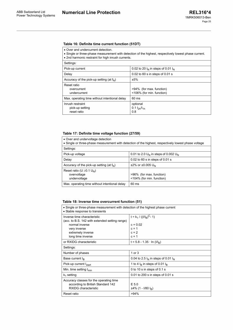
Table 16: Definite time current function (51DT)• Over and undercurrent detection. • Single or three-phase measurement with detection of the highest, respectively lowest phase current. • 2nd harmonic restraint for high inrush currents.
Settings:
Pick-up current 0.02 to 20 IN in steps of 0.01 INDelay 0.02 to 60 s in steps of 0.01 s
Accuracy of the pick-up setting (at fN) ±5%
Reset ratioovercurrentundercurrent
>94% (for max. function)<106% (for min. function)
Max. operating time without intentional delay 60 ms
Inrush restraintpick-up settingreset ratio
optional0.1 I2h/I1h0.8
Table 17: Definite time voltage function (27/59)• Over and undervoltage detection• Single or three-phase measurement with detection of the highest, respectively lowest phase voltage
Settings:
Pick-up voltage 0.01 to 2.0 UN in steps of 0.002 UN
Delay 0.02 to 60 s in steps of 0.01 s
Accuracy of the pick-up setting (at fN) ±2% or ±0.005 UN
Reset ratio (U ≥0.1 UN)overvoltageundervoltage
>96% (for max. function)<104% (for min. function)
Max. operating time without intentional delay 60 ms
Table 18: Inverse time overcurrent function (51)• Single or three-phase measurement with detection of the highest phase current• Stable response to transients
Inverse time characteristic(acc. to B.S. 142 with extended setting range)
normal inversevery inverseextremely inverselong time inverse
t = k1 / ((I/IB)C- 1)
c = 0.02c = 1c = 2c = 1
or RXIDG characteristic t = 5.8 - 1.35 · In (I/IB)
Settings:
Number of phases 1 or 3
Base current IB 0.04 to 2.5 IN in steps of 0.01 INPick-up current Istart 1 to 4 IB in steps of 0.01 IBMin. time setting tmin 0 to 10 s in steps of 0.1 s
k1 setting 0.01 to 200 s in steps of 0.01 s
Accuracy classes for the operating time according to British Standard 142RXIDG characteristic
E 5.0±4% (1 - I/80 IB)
Reset ratio >94%
Numerical Line Protection REL316*41MRK506013-Ben
Page 26
ABB Switzerland LtdPower Technology Systems
Technical data func-tions (cont’d)Technical data func-tions (cont’d)
Table 19: Inverse time ground fault overcurrent function (51N)• Neutral current measurement (derived externally or internally) • Stable response to transients
Inverse time characteristic(acc. to B.S. 142 with extended setting range)
normal inversevery inverseextremely inverselong time inverse
t = k1 / ((I/IB)C - 1)
c = 0.02c = 1c = 2c = 1
or RXIDG characteristic t = 5.8 - 1.35 · In (I/IB)
Settings:
Number of phases 1 or 3
Base current IB 0.04 to 2.5 IN in steps of 0.01 INPick-up current Istart 1 to 4 IB in steps of 0.01 IBMin. time setting tmin 0 to 10 s in steps of 0.1 s
k1 setting 0.01 to 200 s in steps of 0.01 s
Accuracy classes for the operating time according to British Standard 142RXIDG characteristic
• Three-phase measurement• Suppression of DC- and high-frequency components• Definite time characteristic• Voltage memory feature for close faults
Settings:
Current 0.02 to 20 IN in steps of 0.01 INAngle -180° to +180° in steps of 15°
Delay 0.02 s to 60 s in steps of 0.01 s
tWait 0.02 s to 20 s in steps of 0.01 s
Memory duration 0.2 s to 60 s in steps of 0.01 s
Accuracy of pick-up setting (at fN)Reset ratioAccuracy of angle measurement(at 0.94 to 1.06 fN)
±5% or ±0.02 IN>94%
±5°
Voltage input rangeVoltage memory rangeAccuracy of angle measurement at voltage memoryFrequency dependence of angle measurement at voltage memoryMax. Response time without delay
0.005 to 2 UN<0.005 UN±20°
±0.5°/Hz60 ms
Numerical Line ProtectionABB Switzerland LtdPower Technology Systems
REL316*41MRK506013-Ben
Page 27
Table 21: Directional inverse time overcurrent function (67)• Directional overcurrent protection with detection of the power direction• Back-up protection for distance protection scheme
• Three-phase measurement• Suppression of DC- and high-frequency components• Inverse time characteristic• Voltage memory feature for close faults
Settings:
Current I-Start 1…4 IB in steps of 0.01 IBAngle -180°…+180° in steps of 15°
Inverse time characteristic(acc. to B.S. 142 with extended setting range)
normal inverse very inverse extremely inverse long-time earth fault
t = k1 / ((I/IB)C- 1)
c = 0,02c = 1c = 2c = 1
k1-setting 0.01 to 200 s in steps of 0.01 s
t-min 0 to 10 s in steps of 0.1 s
IB-value 0.04 to 2.5 IN in steps of 0.01 INtWait 0.02 s to 20 s in steps of 0.01 s
Memory duration 0.2 s to 60 s in steps of 0.01 s
Accuracy of pick-up setting (at fN)Reset ratioAccuracy of angle measurement (at 0.94 to 1.06 fN)Accuracy class of the operating time acc. to British Standard 142
±5%>94%±5°
E 10
Voltage input rangeVoltage memory rangeAccuracy of angle measurement at voltage memoryFrequency dependence of angle measurement at voltage memoryMax. Response time without delay
0.005 to 2 UN<0.005 UN±20°
±0.5°/Hz60 ms
Table 22: Directional ground fault function for ungrounded systems and systems with Petersen coils (32N)
Determination of real or apparent power from neutral current and voltage
Settings:
Pick-up power 0.005 to 0.1 SN in steps of 0.001 SN
Reference value of the power SN 0.5 to 2.5 UN · IN in steps of 0.001 UN · INCharacteristic angle -180° to +180° in steps of 0.01°
Phase error compensation of current input -5° to +5° in steps of 0.01°
Delay 0.05 to 60 s in steps of 0.01 s
Reset ratio 30 to 95% in steps of 1%
Accuracy of the pick-up setting ±10% of setting or 2% UN · IN(for protection CTs) ±3% of setting or 0.5% UN · IN(for core-balance CTs)
Max. operating time without intentional delay 70 ms
Numerical Line Protection REL316*41MRK506013-Ben
Page 28
ABB Switzerland LtdPower Technology Systems
Technical data func-tions (cont’d)Technical data func-tions (cont’d)
Table 24: Metering function UIfPQ
Table 23: Directional ground fault function for grounded systems (67N)• Detection of high-resistance ground faults• Current enabling setting 3I0• Direction determined on basis of neutral variables (derived externally or internally)• Permissive or blocking directional comparison scheme• Echo logic for weak infeeds• Logic for change of energy direction
Settings:
Current pick-up setting 0.1 to 1.0 IN in steps of 0.01 INVoltage pick-up setting 0.003 to 1 UN in steps of 0.001 UN
Characteristic angle -90° to +90° in steps of 5°
Delay 0 to 1 s in steps of 0.001 s
Accuracy of the current pick-up setting ±10% of setting
• Single-phase measurement of voltage, current, frequency, real power and apparent power• Choice of measuring phase-to-ground or phase-to-phase voltages• Suppression of DC components and harmonics in current and voltage• Compensation of phase errors in main and input CTs and VTs
Settings:
Phase angle -180° to +180° in steps of 0.1°
Reference value of the power SN 0.2 to 2.5 SN in steps of 0.001 SN
Refer to Table 33 for accuracy.
Table 25: Three-phase measuring module• Three-phase measurement of voltage (star or delta), current, frequency, real and apparent power and
power factor. • Two independent impulse counter inputs for calculation of interval and accumulated energy. The three-
phase measurement and the impulse counters can be used independently and may also be disabled. • This function may be configured four times.
Settings:
Angle -180° to +180° in steps of 0.1°
Reference value for power 0.2 to 2.5 SN in steps of 0.001 SN
t1-Interval 1 min, 2 min, 5 min, 10 min, 15 min, 20 min, 30 min, 60 min or 120 min
Scale factor of power 0.0001 to 1
Max. impulse frequency 25 Hz
Min. impulse durationAccuracy of time interval
10 ms±100 ms
See Table 33 for accuracy
Numerical Line ProtectionABB Switzerland LtdPower Technology Systems
REL316*41MRK506013-Ben
Page 29
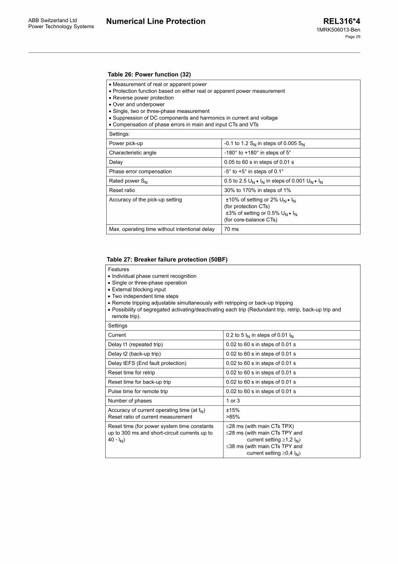
Table 26: Power function (32)• Measurement of real or apparent power• Protection function based on either real or apparent power measurement• Reverse power protection• Over and underpower• Single, two or three-phase measurement• Suppression of DC components and harmonics in current and voltage• Compensation of phase errors in main and input CTs and VTs
Settings:
Power pick-up -0.1 to 1.2 SN in steps of 0.005 SN
Characteristic angle -180° to +180° in steps of 5°
Delay 0.05 to 60 s in steps of 0.01 s
Phase error compensation -5° to +5° in steps of 0.1°
Rated power SN 0.5 to 2.5 UN • IN in steps of 0.001 UN • INReset ratio 30% to 170% in steps of 1%
Accuracy of the pick-up setting ±10% of setting or 2% UN • IN(for protection CTs) ±3% of setting or 0.5% UN • IN(for core-balance CTs)
Max. operating time without intentional delay 70 ms
Table 27: Breaker failure protection (50BF)Features• Individual phase current recognition• Single or three-phase operation• External blocking input• Two independent time steps• Remote tripping adjustable simultaneously with retripping or back-up tripping• Possibility of segregated activating/deactivating each trip (Redundant trip, retrip, back-up trip and
remote trip).
Settings
Current 0.2 to 5 IN in steps of 0.01 INDelay t1 (repeated trip) 0.02 to 60 s in steps of 0.01 s
Delay t2 (back-up trip) 0.02 to 60 s in steps of 0.01 s
Delay tEFS (End fault protection) 0.02 to 60 s in steps of 0.01 s
Reset time for retrip 0.02 to 60 s in steps of 0.01 s
Reset time for back-up trip 0.02 to 60 s in steps of 0.01 s
Pulse time for remote trip 0.02 to 60 s in steps of 0.01 s
Number of phases 1 or 3
Accuracy of current operating time (at fN)Reset ratio of current measurement
±15%>85%
Reset time (for power system time constants up to 300 ms and short-circuit currents up to 40 · IN)
≤28 ms (with main CTs TPX)≤28 ms (with main CTs TPY and
current setting ≥1,2 IN)≤38 ms (with main CTs TPY and
current setting ≥0,4 IN)
Numerical Line Protection REL316*41MRK506013-Ben
Page 30
ABB Switzerland LtdPower Technology Systems
Technical data func-tions (cont’d)Technical data func-tions (cont’d)
Table 28: Disturbance recorder
Ancillary functions
Table 29: Logic
Table 30: Delay/integrator
Table 31: Plausibility check
• Max. 9 CT/VT channels• Max. 16 binary channels• Max. 12 analog channels of internal measurement values• 12 samples per period (sampling frequency 600 or 720 Hz at a rated frequency of 50/60 Hz)• Available recording time for 9 CT/VT- and 8 binary signals approximately 5 s• Recording initiated by any binary signal, e.g. the general trip signal.
Data format EVE
Dynamic range 70 x IN, 1.3 x UN
Resolution 12 bits
Settings:
Recording periods Pre-event EventPost-event
40 to 400 ms in steps of 20 ms100 to 3000 ms in steps of 50 ms40 to 400 ms in steps of 20 ms
Logic for 4 binary inputs with the following 3 configurations:1. OR gate2. AND gate3. Bistable flip-flop with 2 set and 2 reset inputs (both OR gates), resetting takes priority
All configurations have an additional blocking input.Provision for inverting all inputs.
• For delaying pick-up or reset or for integrating 1 binary signal• Provision for inverting the input
Settings:
Pick-up or reset time 0 to 300 s in steps of 0.01 s
Integration yes/no
A plausibility check function is provided for each three-phase current and three-phase voltage input which performs the following:• Determination of the sum and phase sequence of the three-phase currents or voltages• Provision for comparison of the sum of the phase values with a corresponding current or voltage sum
applied to an input• Function blocks for currents exceeding 2 x IN, respectively voltages exceeding 1.2 UN
Accuracy of the pick-up setting at rated frequency ±2% IN in the range 0.2 to 1.2 IN±2% UN in the range 0.2 to 1.2 UN
Reset ratio ≥90% whole range>95% (at U >0.1 UN or I >0.1 IN)
Current plausibility settings:Pick-up differential for sum of internal summation current or between internal and external summation currents 0.05 to 1.00 IN in steps of 0.05 INAmplitude compensation for summation CT -2.00 to +2.00 in steps of 0.01
Delay 0.1 to 60 s in steps of 0.1 s
Numerical Line ProtectionABB Switzerland LtdPower Technology Systems
REL316*41MRK506013-Ben
Page 31
SN = √3 ⋅ UN ⋅ IN (three-phase)SN = 1/3 ⋅ √3 ⋅ UN ⋅ IN (single-phase)
Voltage plausibility settings:Pick-up differential for sum of internal summation voltage or between internal and external summation voltages 0.05 to 1.2 UN in steps of 0.05 UN
Amplitude compensation for summation VT -2.00 to +2.00 in steps of 0.01
Delay 0.1 to 60 s in steps of 0.1 s
Table 32: Runtime supervisionThe runtime supervision feature enables checking the opening and closing of all kinds of breakers (circuit-breakers, isolators, ground switches...). Failure of a breaker to open or close within an adjustable time results in the creation of a corresponding signal for further processing.
Settings
Setting time 0 to 60 s in steps of 0.01 s
Accuracy of runtime supervision ±2 ms
Table 33: Accuracy of the metering function UIfPQ and three-phase measuring module (including input voltage and input current CT)
Input variable Accuracy Conditions
Core balance CTs with error compensation
Protection CTs without error com-pensation
Voltage ±0.5% UN ±1% UN 0.2 to 1.2 UNf = fN
Current ±0.5% IN ±2% IN 0.2 to 1.2 INf = fN
Real power ±0.5% SN ±3% SN 0.2 to 1.2 SN0.2 to 1.2 UN0.2 to 1.2 INf = fN
Apparent power ±0.5% SN ±3% SN
Power factor ±0.01 ±0.03 S = SN, f = fNFrequency ±0.1% fN ±0.1% fN 0.9 to 1,1 fN
0.8 to 1,2 UN
Numerical Line ProtectionABB Switzerland LtdPower Technology Systems
REL316*41MRK506013-Ben
Page 32
Connection diagram
Fig. 9 Typical wiring diagram of REL316*4 in size N1 casing with two input/output units 316DB62
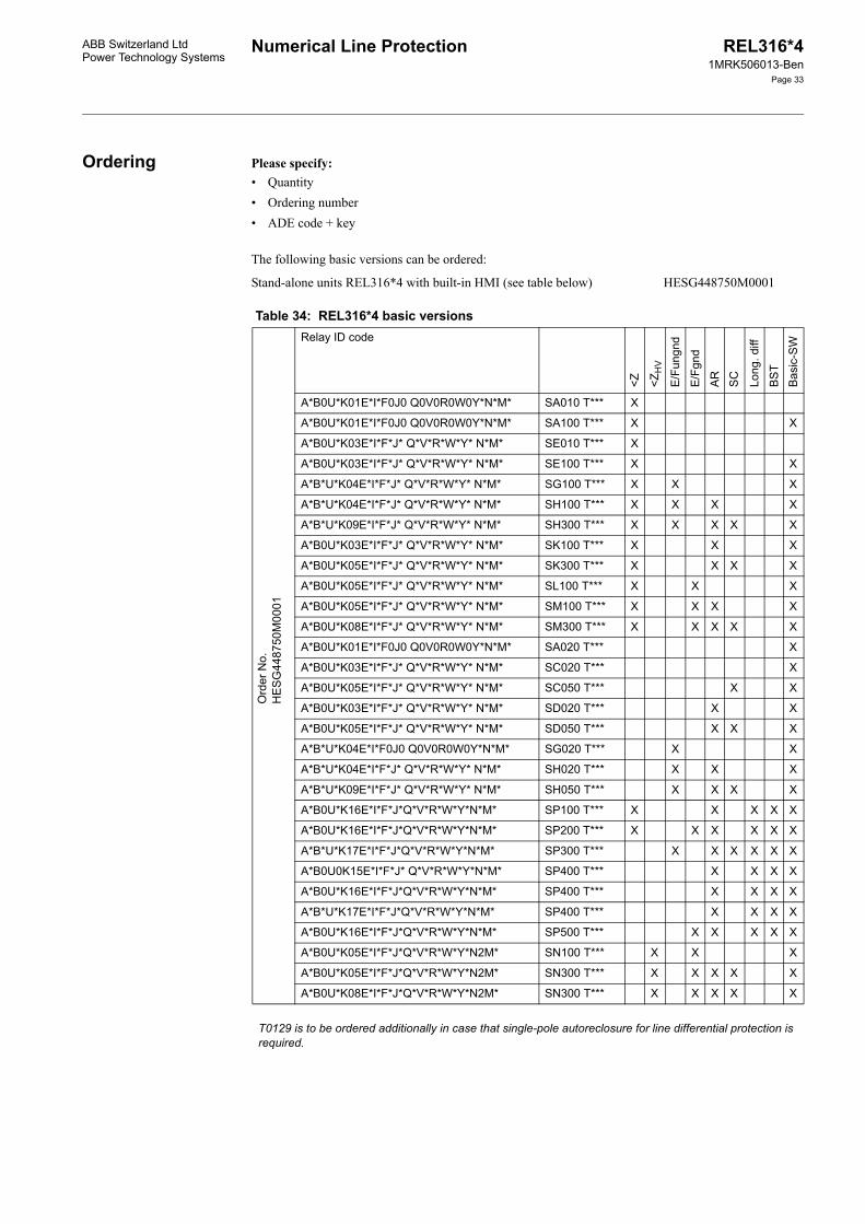
Stand-alone units REL316*4 with built-in HMI (see table below) HESG448750M0001
Table 34: REL316*4 basic versions
Ord
er N
o.H
ES
G44
8750
M00
01
Relay ID code
<Z <ZH
V
E/F
ungn
d
E/F
gnd
AR
SC
Long
. diff
BS
TB
asic
-SW
A*B0U*K01E*I*F0J0 Q0V0R0W0Y*N*M* SA010 T*** X
A*B0U*K01E*I*F0J0 Q0V0R0W0Y*N*M* SA100 T*** X X
A*B0U*K03E*I*F*J* Q*V*R*W*Y* N*M* SE010 T*** X
A*B0U*K03E*I*F*J* Q*V*R*W*Y* N*M* SE100 T*** X X
A*B*U*K04E*I*F*J* Q*V*R*W*Y* N*M* SG100 T*** X X X
A*B*U*K04E*I*F*J* Q*V*R*W*Y* N*M* SH100 T*** X X X X
A*B*U*K09E*I*F*J* Q*V*R*W*Y* N*M* SH300 T*** X X X X X
A*B0U*K03E*I*F*J* Q*V*R*W*Y* N*M* SK100 T*** X X X
A*B0U*K05E*I*F*J* Q*V*R*W*Y* N*M* SK300 T*** X X X X
A*B0U*K05E*I*F*J* Q*V*R*W*Y* N*M* SL100 T*** X X X
A*B0U*K05E*I*F*J* Q*V*R*W*Y* N*M* SM100 T*** X X X X
A*B0U*K08E*I*F*J* Q*V*R*W*Y* N*M* SM300 T*** X X X X X
A*B0U*K01E*I*F0J0 Q0V0R0W0Y*N*M* SA020 T*** X
A*B0U*K03E*I*F*J* Q*V*R*W*Y* N*M* SC020 T*** X
A*B0U*K05E*I*F*J* Q*V*R*W*Y* N*M* SC050 T*** X X
A*B0U*K03E*I*F*J* Q*V*R*W*Y* N*M* SD020 T*** X X
A*B0U*K05E*I*F*J* Q*V*R*W*Y* N*M* SD050 T*** X X X
A*B*U*K04E*I*F0J0 Q0V0R0W0Y*N*M* SG020 T*** X X
A*B*U*K04E*I*F*J* Q*V*R*W*Y* N*M* SH020 T*** X X X
A*B*U*K09E*I*F*J* Q*V*R*W*Y* N*M* SH050 T*** X X X X
A*B0U*K16E*I*F*J*Q*V*R*W*Y*N*M* SP100 T*** X X X X X
A*B0U*K16E*I*F*J*Q*V*R*W*Y*N*M* SP200 T*** X X X X X X
A*B*U*K17E*I*F*J*Q*V*R*W*Y*N*M* SP300 T*** X X X X X X
A*B0U0K15E*I*F*J* Q*V*R*W*Y*N*M* SP400 T*** X X X X
A*B0U*K16E*I*F*J*Q*V*R*W*Y*N*M* SP400 T*** X X X X
A*B*U*K17E*I*F*J*Q*V*R*W*Y*N*M* SP400 T*** X X X X
A*B0U*K16E*I*F*J*Q*V*R*W*Y*N*M* SP500 T*** X X X X X
A*B0U*K05E*I*F*J*Q*V*R*W*Y*N2M* SN100 T*** X X X
A*B0U*K05E*I*F*J*Q*V*R*W*Y*N2M* SN300 T*** X X X X X
A*B0U*K08E*I*F*J*Q*V*R*W*Y*N2M* SN300 T*** X X X X X
T0129 is to be ordered additionally in case that single-pole autoreclosure for line differential protection is required.
Numerical Line Protection REL316*41MRK506013-Ben
Page 34
ABB Switzerland LtdPower Technology Systems
Ordering (cont’d)Ordering (cont’d) Legend:* required sub-code in Table 35<Z distance protection<ZHV high-voltage distance protection E/Fungnd direction ground fault function for ungrounded systems or systems with Petersen coilsE/Fgnd direction ground fault function for grounded systemsAR autoreclosureSC synchrocheckLong. diff. longitudinal differential functionBST binary signal transmission
Basic SW Basic software including the following functions:OCDT definite time overcurrentOCDT Dir directional definite time overcurrent protectionOCDT Inv Dir directional inverse time overcurrent protectionVTDT definite time voltage functionTH thermal overloadPower power functionOCInv inverse definite minimum time-overcurrentUcheck voltage plausibilityIcheck current plausibilityUlfPQ meteringMeasMod three-phase measuring moduleDelay delay/integratorLogic AND gate, OR gate or bistable flip-flopFUPLA project-specific logicDRec disturbance recorderl0inv inverse time ground fault overcurrent functionBFP breaker failure protectionRTS runtime supervision
All the functions of the basic versions can be applied in any combination providing the maximum capacity of the processor and the number of analog channels is not exceeded.
The basic versions with the longitudinal differential function include the additional 316EA62 board and another back plate.
Numerical Line ProtectionABB Switzerland LtdPower Technology Systems
REL316*41MRK506013-Ben
Page 35
Table 35: Definitions of the relay ID codes in Table 34Sub code Significance Description Remarks
none82 to 312 V DC36 to 75 V DC18 to 36 V DC175 to 312 V DC
2. binary input/output unitoptocoupler input voltage
state
Q- Q0 none
Q1 8 optocoupler6 signal. relays2 command relays
3. binary input/output unit Type 316DB61
see previous table
Q2 4 optocoupler10 signal. relays2 command relays
3. binary input/output unit Type 316DB62
Q3 14 optocoupler8 signal. relays
3. binary input/output unit Type 316DB63
V- V0V3V4V5V9
none82 to 312 V DC36 to 75 V DC18 to 36 V DC175 to 312 V DC
3. binary input/output unitoptocoupler input voltage
state
Numerical Line ProtectionABB Switzerland LtdPower Technology Systems
REL316*41MRK506013-Ben
Page 37
1) MVB interface (for interbay or process bus) not applicable for surface-mounted version.
The order number has been defined for the basic version as above and the required accessories can be ordered according to the following Table.
Sub code Significance Description Remarks
R- R0 none
R1 8 optocoupler6 signal. relays2 command relays
4. binary input/output unit Type 316DB61
see previous table
R2 4 optocoupler10 signal. relays2 command relays
4. binary input/output unit Type 316DB62
R3 14 optocoupler8 signal. relays
4. binary input/output unit Type 316DB63
W- W0W3W4W5W9
none82 to 312 V DC36 to 75 V DC18 to 36 V DC175 to 312 V DC
4. binary input/output unitoptocoupler input voltage
state
Y- Y0Y1Y2Y3Y41)
no comm. protocolSPA IEC 60870-5-103LONMVB (part of IEC 61375)
Interbay bus protocol
N- N1N2
casing width 225.2 mmcasing width 271 mm
see previous table
M- M1M51)
Semi-flush mountingSurface mounting, standard ter-minals
Order M1 and sepa-rate assembly kit for 19" rack mounting
S- SA000toSO990
basic versions REL316*4without differential function
Different versions of func-tions
see previous table
SP000toSQ990
basic versions REL316*4with differential function
SZ990 order not acc. to Data Sheet
T- T000T001xtoT999x
without FUPLA logicFUPLA logic
Customer-specific logicx = version of the FUPLA logic
Defined by ABB Switzerland Ltd
T129x
T141x
T142x
Logic for single-phaseautoreclosure for line differ-ential protectionLogic for single-phase autoreclosure for the distance protection with a 1½-breaker schemeLogic for single-phase autoreclosure for a reclosure unit with a 1½-breaker scheme
Numerical Line Protection REL316*41MRK506013-Ben
Page 38
ABB Switzerland LtdPower Technology Systems
Ordering (cont’d)Ordering (cont’d)
Table 36: AccessoriesAssembly kits
Item Description Order No.
19"-mounting plate for hinged frames, light-beige for use with:1 1 REL316*4 (size 1 casing)2 2 REL316*4 (size 1 casing)3 1 REL316*4 (size 2 casing)4 1 REL316*4 and 1 test socket block XX93, Test adapter and accessories:5 Semi-flush test socket block for Item 46 Test kit including 19" mounting plate to fit 1 REL316*4 in a hinged frame7 Test kit1 for semi-flush panel mounting8 Test kit1 for surface mounting9 Test socket block for surface mounting10 Connecting cable XX93/XS92b for use with Items 5 and 911 Test plug with 4 mm terminals for use with test set 316TSS0112 Connecting cable for XS92b with 4 mm terminals for use with test plug RTXH2413 1 REL316*4 size 1, surface mounting kit14 1 REL316*4 size 2, surface mounting kit
1 A test kit Type 316TSS01 comprises:- casing for semi-flush or surface mounting- test socket block RTXP24.
Fig. 13 Surface mounting, casing able to swing to the left, rear connections. Size N2 casing.
Numerical Line Protection REL316*41MRK506013-Ben
Page 43
ABB Switzerland LtdPower Technology Systems
Example of an order
• Rated current 1 A, rated voltage 100 V AC• 3-phase voltages, 3-phase currents, 1 neu-
tral current• 110 V DC aux. supply• 4 heavy duty relays (3 tripping, 1 CB clos-
ing), 20 signalling relays• 8 optocoupler inputs (110 V DC)• 1 relay for 19" rack mounting• Distance protection function (Z starters
with provision for all transfer tripping schemes)
• Autoreclosure• Communication with the station control
system (e.g. LON)• Operator program on CD.
The corresponding order is as follows:
• 1 REL316*4, HESG448750M0001• 110 V DC aux. supply• Optocoupler input voltage 110 V DC• Rated current 1 A
• Rated voltage 100 V AC• 1 mounting kit HESG324310P1• 1 electro-optical converter
HESG448267R401• 1 CD RE.216 / RE.316*4
1MRB260030M0001• 1 PC connecting cable (if not already
available) 1MRB380084-R1.
Alternatively, the relay ID code may be given instead. In this case the order would be:
• 1 REL316*4, A1B0U1K03E2I3F2J3Y1N1M1SK100T0
• 1 mounting kit HESG324310P1• 1 CD RE.216 / RE.316*4
1MRB260030M0001• 1 electro-optical converter
HESG448267R401• 1 PC connecting cable (if not already
available) 1MRB380084-R1.
Relay ID codes are marked on all relays. The significance of the sub-codes can be seen from Table 35.
Example of a specification
Numerical line protection terminal with ex-tensive self-supervision of the internal func-tions and A/D conversion of all input vari-ables. The terminal shall be suitable for the protection of single and double-circuit lines and cables in solidly or low-impedance grounded systems, ungrounded systems and systems with Petersen coils. It shall be capa-ble of detecting all kinds of power system faults including close three-phase faults, cross-country faults (in ungrounded systems or systems with Petersen coils), evolving faults and high-resistance ground faults. Due account shall be taken of power swings and changes in the direction of energy flow.
The distance protection terminal shall have at least three distance zones with independent settings and in addition zones of measure-ment for all the usual transfer tripping sche-mes. Provision shall be made for compensat-ing the mutual impedance in the case of par-allel circuit lines using the neutral current of the parallel circuit to obtain a correct setting. The integrity of the VT circuit shall be super-vised.
The longitudinal differential protection termi-nal shall measure the three phases indepen-dently and permit other protection signals to
be transmitted via the same communications channel. Provision shall be made for the com-bination with a distance protection scheme, a directional ground fault scheme and back-up functions.
The protection functions shall be in the form of software such that additional or different functions, i.e. power swing blocking, sensi-tive ground fault, overcurrent, thermal over-load, single or three-phase autoreclosure, application-specific logics etc., can be readily implemented without changes to the existing hardware. All configuration and setting oper-ations shall be made using a menu-based operator program running on a PC connected locally to the terminal for the purpose.
The assignment of input and output signals to the protection functions shall be possible lar-gely without restrictions. An event recorder with fault locator function shall be provided.
The data exchange between the control sys-tem and the station control system shall be ensured via a communication interface. The data connection itself shall be able to be de-signed with fiberoptic conductors.
Numerical Line ProtectionABB Switzerland LtdPower Technology Systems
REL316*41MRK506013-Ben
Page 44
Other relevant documents
Operating Instructions REL316*4 (printed) 1MRB520050-UenOperating Instructions REL316*4 (CD) 1MRB260030M0001Operating Instructions Testing program using XS92b CH-ES 86-11.52 EData Sheet CAP316 1MRB520167-BenData Sheet Test Set XS92b 1MRB520006-BenReference List REL316*4 1MRB520212-RenDescription Current transformer requirements CH-ES 45-12.30 EData Sheet SigTOOL 1MRB520158-BenData Sheet RIO580 1MRB520176-Ben