1 Relationship between Cross-Polarization Discrimination (XPD) and Spatial Correlation in Indoor Small-Cell MIMO Systems Yeon-Geun Lim, Student Member, IEEE, Yae Jee Cho, Student Member, IEEE, TaeckKeun Oh, Member, IEEE, Yongshik Lee, Senior Member, IEEE, and Chan-Byoung Chae, Senior Member, IEEE Abstract—In this letter, we present a correlated channel model for a dual-polarization antenna to omnidirectional antennas in in- door small-cell multiple-input multiple-output (MIMO) systems. In an indoor environment, we confirm that the cross-polarization discrimination (XPD) in the direction of angle-of-departure can be represented as the spatial correlation of the MIMO channel. We also evaluate a dual-polarization antenna-based MIMO channel model and a spatially correlated channel model using a three-dimensional (3D) ray-tracing simulator. Furthermore, we provide the equivalent distance between adjacent antennas according to the XPD, providing insights into designing a dual- polarization antenna and its arrays. Index Terms—Dual-polarization antenna, XPD, MIMO, spatial correlation, and 3D ray-tracing. I. I NTRODUCTION Researchers have been able to extend mobile service coverage and network capacity through their development of small-cell technology [1]. In next-generation communi- cations, researchers are considering multiple-input multiple- output (MIMO) techniques [2]. One such technique is massive MIMO, in which base stations (BSs) are equipped with many antennas to increase capacity and to conserve energy [3], [4]. To establish MIMO schemes in small-cell systems, researchers must address certain issues. MIMO capacity can be degraded, for example, by a compact antenna array for small-sized BS. The degradation is due to the high spatial correlation of channels [3], [5]. A good solution for installing a compact antenna array could involve a collocated dual-polarization an- tenna system. One dual-polarization antenna could then play, equivalently, the roles of two dipole/patch-type antennas as long as there is high cross-polarization discrimination (XPD). Here, XPD is the ratio of the copolarization received power and the cross-polarization received power. To establish a dual-polarized MIMO system, we should investigate channel modeling, which is critical for performance evaluation [6]. In prior work [7], [8], the authors focused Y.-G. Lim, Y. J. Cho, and C.-B. Chae are with School of Inte- grated Technology, Yonsei University, Korea (e-mail: yglim, yjenncho, [email protected]). T. Oh is with LIG Nex1, Korea (e-mail: taeck- [email protected]). Y. Lee is with School of Electrical and Electronic Engineering, Yonsei University, Korea (e-mail: [email protected]). This research was supported by the MSIP (Ministry of Science, ICT and Future Planning), Korea, under the “IT Consilience Creative Program” (IITP- R0346-16-1008) supervised by the IITP and ICT R&D program of MSIP/IITP (2015-0-00300). on the channel from a dual-polarization antenna to a dual- polarization antenna. Meanwhile, it is also important, in prac- tice, to study channels from a dual-polarization antenna to dipole/patch-type antennas because a typical MS is likely to be equipped with dipole/patch-type antennas. It is necessary to have, as noted above, a high XPD to set up dual-polarized MIMO systems. Researchers have developed dual-polarization antennas that have a high XPD in the main direction of radiation [9], [10]. It is also important, on the other hand, to consider the average XPD in all directions in indoor environments, for signals go through a wall-induced reflection in all directions [11]. While the conventional approach to designing a dual-polarization antenna with high XPD provides better MIMO performance, it is a costly and complex process to make this antenna at a small size. From this perspective, it remains an open question as to how much XPD is needed to sustain MIMO performance at reasonable cost and level of complexity. In this letter, we provide a correlated channel model for a dual-polarization antenna to omnidirectional antennas in indoor small-cell MIMO systems. This channel model re- flects the relationship of XPD in the direction of angle-of- departure (AoD) of a dual-polarization antenna and correlation of MIMO channel. We evaluate the dual-polarization antenna- based MIMO channel model by using a three-dimensional (3D) ray-tracing simulator that can exploit physically spe- cific behaviors of the polarized channel [12], [13]. We also investigate the equivalent distance between adjacent antennas according to the XPD. We provide insight into the XPD design aspect for a dual-polarization antenna at a small size and at a reasonable cost and level of complexity. To the best of our knowledge, this letter is the first work to explain and validate the relationship between an XPD and spatial correlation by utilizing the presented channel model and a 3D ray-tracing tool. In 3GPP, this problem has been an open issue. II. SYSTEM MODEL Fig. 1 illustrates a block diagram of a dual-polarization antenna-based MIMO system. We consider a single-user MIMO with one collocated dual-polarization antenna that serves one MS equipped with two omnidirectional antennas. This model is considered a 2×2 MIMO system, since hori- zontally and vertically polarized waves are respectively radi- ated from Port-1 and Port-2 of the dual-polarization antenna, arXiv:1707.00227v2 [cs.IT] 6 Dec 2017
Transcript
1
Relationship between Cross-PolarizationDiscrimination (XPD) and Spatial Correlation in
Abstract—In this letter, we present a correlated channel modelfor a dual-polarization antenna to omnidirectional antennas in in-door small-cell multiple-input multiple-output (MIMO) systems.In an indoor environment, we confirm that the cross-polarizationdiscrimination (XPD) in the direction of angle-of-departure canbe represented as the spatial correlation of the MIMO channel.We also evaluate a dual-polarization antenna-based MIMOchannel model and a spatially correlated channel model usinga three-dimensional (3D) ray-tracing simulator. Furthermore,we provide the equivalent distance between adjacent antennasaccording to the XPD, providing insights into designing a dual-polarization antenna and its arrays.
Index Terms—Dual-polarization antenna, XPD, MIMO, spatialcorrelation, and 3D ray-tracing.
I. INTRODUCTION
Researchers have been able to extend mobile servicecoverage and network capacity through their developmentof small-cell technology [1]. In next-generation communi-cations, researchers are considering multiple-input multiple-output (MIMO) techniques [2]. One such technique is massiveMIMO, in which base stations (BSs) are equipped with manyantennas to increase capacity and to conserve energy [3], [4].To establish MIMO schemes in small-cell systems, researchersmust address certain issues. MIMO capacity can be degraded,for example, by a compact antenna array for small-sized BS.The degradation is due to the high spatial correlation ofchannels [3], [5]. A good solution for installing a compactantenna array could involve a collocated dual-polarization an-tenna system. One dual-polarization antenna could then play,equivalently, the roles of two dipole/patch-type antennas aslong as there is high cross-polarization discrimination (XPD).Here, XPD is the ratio of the copolarization received powerand the cross-polarization received power.
To establish a dual-polarized MIMO system, we shouldinvestigate channel modeling, which is critical for performanceevaluation [6]. In prior work [7], [8], the authors focused
Y.-G. Lim, Y. J. Cho, and C.-B. Chae are with School of Inte-grated Technology, Yonsei University, Korea (e-mail: yglim, yjenncho,[email protected]). T. Oh is with LIG Nex1, Korea (e-mail: [email protected]). Y. Lee is with School of Electrical and ElectronicEngineering, Yonsei University, Korea (e-mail: [email protected]).
This research was supported by the MSIP (Ministry of Science, ICT andFuture Planning), Korea, under the “IT Consilience Creative Program” (IITP-R0346-16-1008) supervised by the IITP and ICT R&D program of MSIP/IITP(2015-0-00300).
on the channel from a dual-polarization antenna to a dual-polarization antenna. Meanwhile, it is also important, in prac-tice, to study channels from a dual-polarization antenna todipole/patch-type antennas because a typical MS is likely tobe equipped with dipole/patch-type antennas.
It is necessary to have, as noted above, a high XPD to setup dual-polarized MIMO systems. Researchers have developeddual-polarization antennas that have a high XPD in the maindirection of radiation [9], [10]. It is also important, on the otherhand, to consider the average XPD in all directions in indoorenvironments, for signals go through a wall-induced reflectionin all directions [11]. While the conventional approach todesigning a dual-polarization antenna with high XPD providesbetter MIMO performance, it is a costly and complex processto make this antenna at a small size. From this perspective,it remains an open question as to how much XPD is neededto sustain MIMO performance at reasonable cost and level ofcomplexity.
In this letter, we provide a correlated channel model fora dual-polarization antenna to omnidirectional antennas inindoor small-cell MIMO systems. This channel model re-flects the relationship of XPD in the direction of angle-of-departure (AoD) of a dual-polarization antenna and correlationof MIMO channel. We evaluate the dual-polarization antenna-based MIMO channel model by using a three-dimensional(3D) ray-tracing simulator that can exploit physically spe-cific behaviors of the polarized channel [12], [13]. We alsoinvestigate the equivalent distance between adjacent antennasaccording to the XPD. We provide insight into the XPD designaspect for a dual-polarization antenna at a small size and ata reasonable cost and level of complexity. To the best of ourknowledge, this letter is the first work to explain and validatethe relationship between an XPD and spatial correlation byutilizing the presented channel model and a 3D ray-tracingtool. In 3GPP, this problem has been an open issue.
II. SYSTEM MODEL
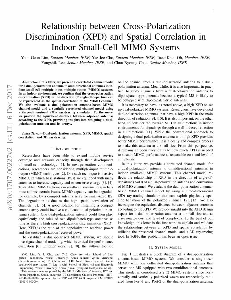
Fig. 1 illustrates a block diagram of a dual-polarizationantenna-based MIMO system. We consider a single-userMIMO with one collocated dual-polarization antenna thatserves one MS equipped with two omnidirectional antennas.This model is considered a 2×2 MIMO system, since hori-zontally and vertically polarized waves are respectively radi-ated from Port-1 and Port-2 of the dual-polarization antenna,
arX
iv:1
707.
0022
7v2
[cs
.IT
] 6
Dec
201
7
2
Fig. 1. Block diagram of the dual-polarization antenna-based MIMO system.
the waves go through the channel almost independently dueto zero cross-correlation between the orthogonally polarizedwaves [6], [11], [14]. Let hrt denote the channel coefficientbetween the tth port at the BS and the rth antenna at theMS, which is an independent and identically distributed (i.i.d.)complex Gaussian random variable with zero mean and unitvariance. From the channel model with a polarization transfermatrix that consists of random phases for different polarizationcombinations in [14], [15], the coefficient of the effectivechannel (HHHeff) is given by
heffrt =
√L−1r,t e
jΦrH√L−1r,t′e
jΦrV
T [√Gφ,αt√Gφ,βt
]=√αrthrt +
√βrt′hrt′ ,
where t 6= t′.1 The notations ΦrH and ΦrV are randominitial phases, the distributions of which are uniform within(−π,+π), for the horizontal and vertical polarization combi-nations at the rth MS antenna. In addition, αrt and βrt are thepropagation gains from copolarization and cross-polarization,and Gφ,αt and Gφ,βt are, respectively, the antenna gain ofcopolarization and cross-polarization in the direction of AoD,which is denoted as φ. Finally, Lr,t is the path loss. Thus,the effective channel can be decomposed into the channelsfrom copolarization and cross-polarization, which is given byHHHeff = HHH +GGG, where
HHH =
[√α11h11
√α12h12√
α21h21√α22h22
], GGG =
[√β12h12
√β11h11√
β22h22
√β21h21
].
We assume that the large-scale parameters from the tth portat the BS are the same, regardless of the antenna index atthe MS (i.e., αrt = αt, βrt = βt and Lr,t = Lt = L). Thisassumption is valid when the MS is a small device [12]. TheXPD at the MS with the corresponding AoD from the tth portof a dual-polarization antenna is then expressed by
χφ,t =Eh[|√αthrt|2]
Eh[|√βt′hrt′ |2]
=αtβt′
=Gφ,αtLrt′
Gφ,βtLrt=Gφ,αtGφ,βt
. (1)
III. CORRELATED CHANNEL MODEL FOR ADUAL-POLARIZATION ANTENNA
From the effective dual-polarization channel, we recognizethat despite of the orthogonal polarization, GGG affects thecorrelation between its components in the real propagation
1The conventional dual-polarization channel models in [6]–[8] can beobtained by letting Gφ,βt = 0. Since they did not consider the propagation ofcross-polarized waves, they applied statistical XPD values to the off-diagonalelements in the polarization transfer matrix.
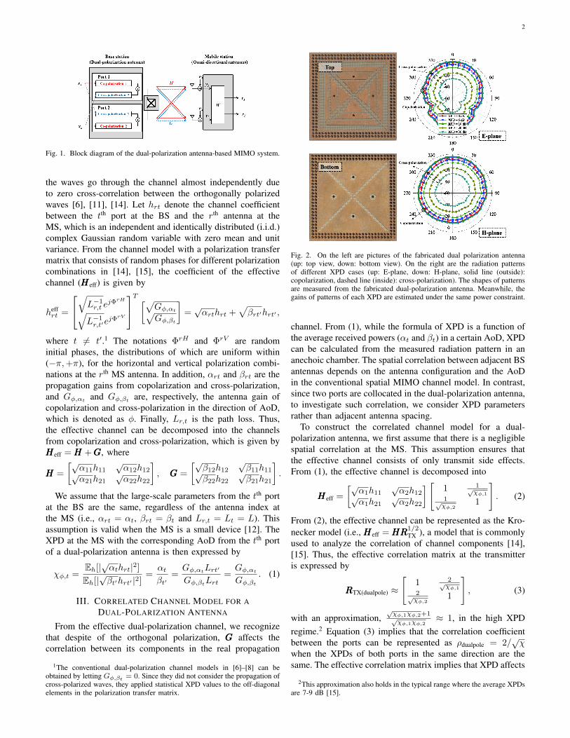
Fig. 2. On the left are pictures of the fabricated dual polarization antenna(up: top view, down: bottom view). On the right are the radiation patternsof different XPD cases (up: E-plane, down: H-plane, solid line (outside):copolarization, dashed line (inside): cross-polarization). The shapes of patternsare measured from the fabricated dual-polarization antenna. Meanwhile, thegains of patterns of each XPD are estimated under the same power constraint.
channel. From (1), while the formula of XPD is a function ofthe average received powers (αt and βt) in a certain AoD, XPDcan be calculated from the measured radiation pattern in ananechoic chamber. The spatial correlation between adjacent BSantennas depends on the antenna configuration and the AoDin the conventional spatial MIMO channel model. In contrast,since two ports are collocated in the dual-polarization antenna,to investigate such correlation, we consider XPD parametersrather than adjacent antenna spacing.
To construct the correlated channel model for a dual-polarization antenna, we first assume that there is a negligiblespatial correlation at the MS. This assumption ensures thatthe effective channel consists of only transmit side effects.From (1), the effective channel is decomposed into
HHHeff =
[√α1h11
√α2h12√
α1h21√α2h22
] [1 1√
χφ,11√χφ,2
1
]. (2)
From (2), the effective channel can be represented as the Kro-necker model (i.e., HHHeff = HHHRRR
1/2TX ), a model that is commonly
used to analyze the correlation of channel components [14],[15]. Thus, the effective correlation matrix at the transmitteris expressed by
RRRTX(dualpole) ≈
[1 2√
χφ,12√χφ,2
1
], (3)
with an approximation,√χφ,1χφ,2+1√χφ,1χφ,2
≈ 1, in the high XPDregime.2 Equation (3) implies that the correlation coefficientbetween the ports can be represented as ρdualpole = 2/
√χ
when the XPDs of both ports in the same direction are thesame. The effective correlation matrix implies that XPD affects
2This approximation also holds in the typical range where the average XPDsare 7-9 dB [15].
3
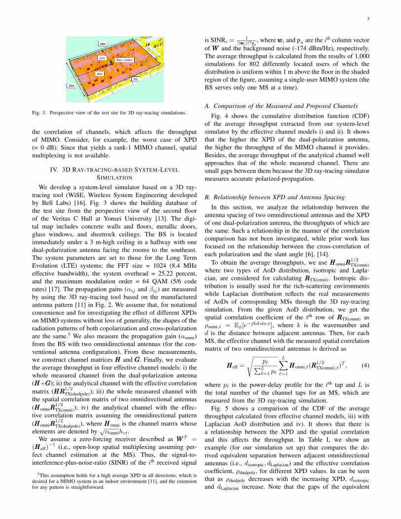
Fig. 3. Perspective view of the test site for 3D ray-tracing simulations.
the correlation of channels, which affects the throughputof MIMO. Consider, for example, the worst case of XPD(= 0 dB). Since that yields a rank-1 MIMO channel, spatialmultiplexing is not available.
IV. 3D RAY-TRACING-BASED SYSTEM-LEVELSIMULATION
We develop a system-level simulator based on a 3D ray-tracing tool (WiSE, Wireless System Engineering developedby Bell Labs) [16]. Fig. 3 shows the building database ofthe test site from the perspective view of the second floorof the Veritas C Hall at Yonsei University [13]. The digi-tal map includes concrete walls and floors, metallic doors,glass windows, and sheetrock ceilings. The BS is locatedimmediately under a 3 m-high ceiling in a hallway with onedual-polarization antenna facing the rooms to the southeast.The system parameters are set to those for the Long TermEvolution (LTE) systems; the FFT size = 1024 (8.4 MHzeffective bandwidth), the system overhead = 25.22 percent,and the maximum modulation order = 64 QAM (5/6 coderates) [17]. The propagation gains (αij and βij) are measuredby using the 3D ray-tracing tool based on the manufacturedantenna pattern [11] in Fig. 2. We assume that, for notationalconvenience and for investigating the effect of different XPDson MIMO systems without loss of generality, the shapes of theradiation patterns of both copolarization and cross-polarizationare the same.3 We also measure the propagation gain (αomni)from the BS with two omnidirectional antennas (for the con-ventional antenna configuration). From these measurements,we construct channel matrices HHH and GGG. Finally, we evaluatethe average throughput in four effective channel models: i) thewhole measured channel from the dual-polarization antenna(HHH+GGG); ii) the analytical channel with the effective correlationmatrix (HHHRRR1/2
TX(dualpole)); iii) the whole measured channel withthe spatial correlation matrix of two omnidirectional antennas(HHHomniRRR
1/2TX(omni)); iv) the analytical channel with the effec-
tive correlation matrix assuming the omnidirectional pattern(HHHomniRRR
1/2TX(dualpole)), where HHHomni is the channel matrix whose
elements are denoted by√αomnihrt.
We assume a zero-forcing receiver described as WWWT =(HHHeff)
−1 (i.e., open-loop spatial multiplexing assuming per-fect channel estimation at the MS). Thus, the signal-to-interference-plus-noise-ratio (SINR) of the ith received signal
3This assumption holds for a high average XPD in all directions, which isdesired for a MIMO system in an indoor environment [11], and the extensionfor any pattern is straightforward.
is SINRi = 1||wwwi||2pn
, wherewwwi and pn are the ith column vectorof WWW and the background noise (-174 dBm/Hz), respectively.The average throughput is calculated from the results of 1,000simulations for 802 differently located users of which thedistribution is uniform within 1 m above the floor in the shadedregion of the figure, assuming a single-user MIMO system (theBS serves only one MS at a time).
A. Comparison of the Measured and Proposed Channels
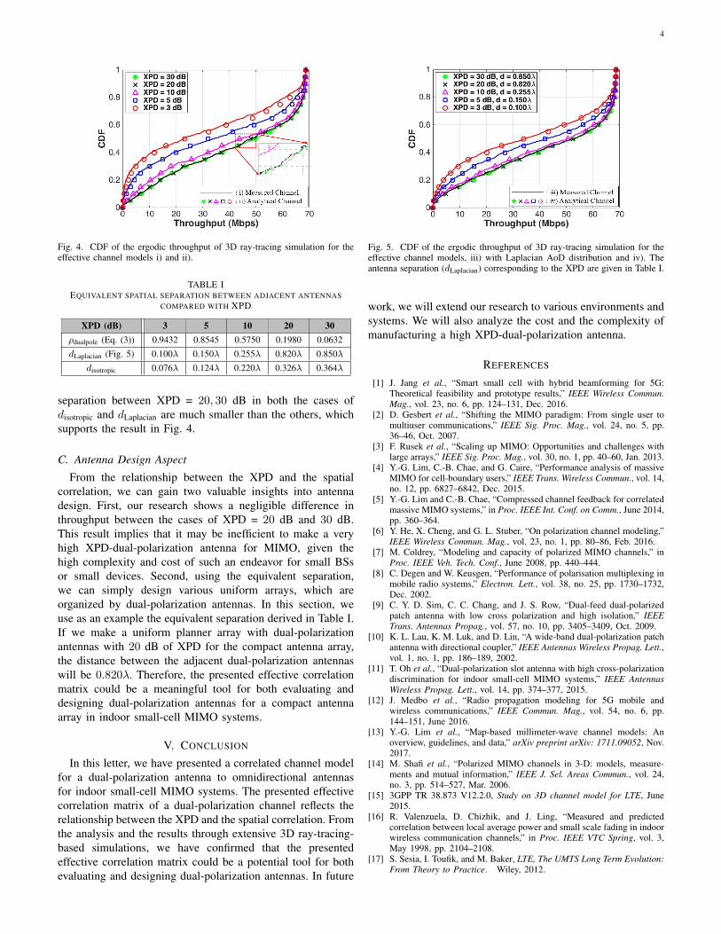
Fig. 4 shows the cumulative distribution function (CDF)of the average throughput extracted from our system-levelsimulator by the effective channel models i) and ii). It showsthat the higher the XPD of the dual-polarization antenna,the higher the throughput of the MIMO channel it provides.Besides, the average throughput of the analytical channel wellapproaches that of the whole measured channel. There aresmall gaps between them because the 3D ray-tracing simulatormeasures accurate polarized-propagation.
B. Relationship between XPD and Antenna Spacing
In this section, we analyze the relationship between theantenna spacing of two omnidirectional antennas and the XPDof one dual-polarization antenna, the throughputs of which arethe same. Such a relationship in the manner of the correlationcomparison has not been investigated, while prior work hasfocused on the relationship between the cross-correlation ofeach polarization and the slant angle [6], [14].
To obtain the average throughputs, we use HHHomniRRR1/2TX(omni)
where two types of AoD distribution, isotropic and Lapla-cian, are considered for calculating RRRTX(omni). Isotropic dis-tribution is usually used for the rich-scattering environmentswhile Laplacian distribution reflects the real measurementsof AoDs of corresponding MSs through the 3D ray-tracingsimulation. From the given AoD distribution, we get thespatial correlation coefficient of the tth row of RRRTX(omni) asρomni,t = Eφ[e−jkd sinφ], where k is the wavenumber andd is the distance between adjacent antennas. Then, for eachMS, the effective channel with the measured spatial correlationmatrix of two omnidirectional antennas is derived as
HHHeff =
√p`∑L`=1 p`
L∑`=1
HHHomni,`(RRR1/2TX(omni),`)
T , (4)
where p` is the power-delay profile for the `th tap and L isthe total number of the channel taps for an MS, which aremeasured from the 3D ray-tracing simulation.
Fig. 5 shows a comparison of the CDF of the averagethroughput calculated from effective channel models, iii) withLaplacian AoD distribution and iv). It shows that there isa relationship between the XPD and the spatial correlationand this affects the throughput. In Table I, we show anexample (for our simulation set up) that compares the de-rived equivalent separation between adjacent omnidirectionalantennas (i.e., disotropic, dLaplacian) and the effective correlationcoefficient, ρdualpole, for different XPD values. In can be seenthat as ρdualpole decreases with the increasing XPD, disotropicand dLaplacian increase. Note that the gaps of the equivalent
4
Fig. 4. CDF of the ergodic throughput of 3D ray-tracing simulation for theeffective channel models i) and ii).
TABLE IEQUIVALENT SPATIAL SEPARATION BETWEEN ADJACENT ANTENNAS
separation between XPD = 20, 30 dB in both the cases ofdisotropic and dLaplacian are much smaller than the others, whichsupports the result in Fig. 4.
C. Antenna Design Aspect
From the relationship between the XPD and the spatialcorrelation, we can gain two valuable insights into antennadesign. First, our research shows a negligible difference inthroughput between the cases of XPD = 20 dB and 30 dB.This result implies that it may be inefficient to make a veryhigh XPD-dual-polarization antenna for MIMO, given thehigh complexity and cost of such an endeavor for small BSsor small devices. Second, using the equivalent separation,we can simply design various uniform arrays, which areorganized by dual-polarization antennas. In this section, weuse as an example the equivalent separation derived in Table I.If we make a uniform planner array with dual-polarizationantennas with 20 dB of XPD for the compact antenna array,the distance between the adjacent dual-polarization antennaswill be 0.820λ. Therefore, the presented effective correlationmatrix could be a meaningful tool for both evaluating anddesigning dual-polarization antennas for a compact antennaarray in indoor small-cell MIMO systems.
V. CONCLUSION
In this letter, we have presented a correlated channel modelfor a dual-polarization antenna to omnidirectional antennasfor indoor small-cell MIMO systems. The presented effectivecorrelation matrix of a dual-polarization channel reflects therelationship between the XPD and the spatial correlation. Fromthe analysis and the results through extensive 3D ray-tracing-based simulations, we have confirmed that the presentedeffective correlation matrix could be a potential tool for bothevaluating and designing dual-polarization antennas. In future
Fig. 5. CDF of the ergodic throughput of 3D ray-tracing simulation for theeffective channel models, iii) with Laplacian AoD distribution and iv). Theantenna separation (dLaplacian) corresponding to the XPD are given in Table I.
work, we will extend our research to various environments andsystems. We will also analyze the cost and the complexity ofmanufacturing a high XPD-dual-polarization antenna.
REFERENCES
[1] J. Jang et al., “Smart small cell with hybrid beamforming for 5G:Theoretical feasibility and prototype results,” IEEE Wireless Commun.Mag., vol. 23, no. 6, pp. 124–131, Dec. 2016.
[2] D. Gesbert et al., “Shifting the MIMO paradigm: From single user tomultiuser communications,” IEEE Sig. Proc. Mag., vol. 24, no. 5, pp.36–46, Oct. 2007.
[3] F. Rusek et al., “Scaling up MIMO: Opportunities and challenges withlarge arrays,” IEEE Sig. Proc. Mag., vol. 30, no. 1, pp. 40–60, Jan. 2013.
[4] Y.-G. Lim, C.-B. Chae, and G. Caire, “Performance analysis of massiveMIMO for cell-boundary users,” IEEE Trans. Wireless Commun., vol. 14,no. 12, pp. 6827–6842, Dec. 2015.
[5] Y.-G. Lim and C.-B. Chae, “Compressed channel feedback for correlatedmassive MIMO systems,” in Proc. IEEE Int. Conf. on Comm., June 2014,pp. 360–364.
[6] Y. He, X. Cheng, and G. L. Stuber, “On polarization channel modeling,”IEEE Wireless Commun. Mag., vol. 23, no. 1, pp. 80–86, Feb. 2016.
[7] M. Coldrey, “Modeling and capacity of polarized MIMO channels,” inProc. IEEE Veh. Tech. Conf., June 2008, pp. 440–444.
[8] C. Degen and W. Keusgen, “Performance of polarisation multiplexing inmobile radio systems,” Electron. Lett., vol. 38, no. 25, pp. 1730–1732,Dec. 2002.
[9] C. Y. D. Sim, C. C. Chang, and J. S. Row, “Dual-feed dual-polarizedpatch antenna with low cross polarization and high isolation,” IEEETrans. Antennas Propag., vol. 57, no. 10, pp. 3405–3409, Oct. 2009.
[10] K. L. Lau, K. M. Luk, and D. Lin, “A wide-band dual-polarization patchantenna with directional coupler,” IEEE Antennas Wireless Propag. Lett.,vol. 1, no. 1, pp. 186–189, 2002.
[11] T. Oh et al., “Dual-polarization slot antenna with high cross-polarizationdiscrimination for indoor small-cell MIMO systems,” IEEE AntennasWireless Propag. Lett., vol. 14, pp. 374–377, 2015.
[12] J. Medbo et al., “Radio propagation modeling for 5G mobile andwireless communications,” IEEE Commun. Mag., vol. 54, no. 6, pp.144–151, June 2016.
[13] Y.-G. Lim et al., “Map-based millimeter-wave channel models: Anoverview, guidelines, and data,” arXiv preprint arXiv: 1711.09052, Nov.2017.
[14] M. Shafi et al., “Polarized MIMO channels in 3-D: models, measure-ments and mutual information,” IEEE J. Sel. Areas Commun., vol. 24,no. 3, pp. 514–527, Mar. 2006.
[15] 3GPP TR 38.873 V12.2.0, Study on 3D channel model for LTE, June2015.
[16] R. Valenzuela, D. Chizhik, and J. Ling, “Measured and predictedcorrelation between local average power and small scale fading in indoorwireless communication channels,” in Proc. IEEE VTC Spring, vol. 3,May 1998, pp. 2104–2108.
[17] S. Sesia, I. Toufik, and M. Baker, LTE, The UMTS Long Term Evolution:From Theory to Practice. Wiley, 2012.