48
RELAY CATALOG

RELAY CATALOG

LABINAL POWER SYSTEMS TF300-9E 32 SAFRAN ELECTRICAL & POWER
SAFRAN ELECTRICAL & POWERSMARTER ELECTRICAL SOLUTIONS FOR A BETTER FLIGHT
At Power we innovate to provide greener, reliable and cost-effective electrical solutions. We are one division "Powering-On" to be a world class trusted supplier.
“Safran Electrical & Power Proprietary Information. Information contained in this document is Safran Electrical & Power Proprietary Information and is disclosed in confidence. It is the property of Safran Electrical & Power and shall not be used, disclosed to others, or reproduced without the express written agreement of Safran Electrical & Power. If consent is given for reproduction in whole or in part, this notice set forth on each page of this document shall appear in any such reproduction in whole or in part. Unauthorized export or re-export is prohibited.”

SAFRAN ELECTRICAL & POWER 32 LABINAL POWER SYSTEMS TF300-9E
RELAY CATALOG
Capabilities and Featured Products
Remote Controlled Circuit Breakers
Power Relays
Hermetically Sealed Power Relays
Lightweight Relays
Generator Contactors
Custom Flat Packs
Table of ContentsFast Information FinderPart Number to Page Index
Capabilities and Featured ProductsSafran Electrical & Power CapabilitiesFeatured Products Article(High Volt DC / Next Generation Contactors / Power Distribution Boxes)
Remote Controlled Circuit BreakersRemote Controlled Circuit BreakersRemote Power Controllers
Power RelaysGasket Sealed - 100 to 1000AGasket Sealed - 25 to 400A, Type II and Type III
Hermetically Sealed Power Relays Hermetically Sealed - 12 to 50AHermetically Sealed - 100 to 400ATerminal Covers
Lightweight RelaysHermetically SealedEnvironmentally Sealed
Generator Contactors
Custom Flat Packs
ReferenceMilitary to Safran Electrical & Power Part Number Index
344
5-8
9-20
21-30
31-37
38-41
42-43
44-46
46
Table of Contents
Reference
“Safran Electrical & Power Proprietary Information. Information contained in this document is Safran Electrical & Power Proprietary Information and is disclosed in confidence. It is the property of Safran Electrical & Power and shall not be used, disclosed to others, or reproduced without the express written agreement of Safran Electrical & Power. If consent is given for reproduction in whole or in part, this notice set forth on each page of this document shall appear in any such reproduction in whole or in part. Unauthorized export or re-export is prohibited.”
LABINAL POWER SYSTEMS TF300-9E 54 SAFRAN ELECTRICAL & POWER
FAST INFORMATION FINDER
Find Information Fast
• Have a Safran Electrical& Power part numberand need moreinformation? Use thepart number to pageindex on this page to getthe exact page of the fullproduct listing.
• Have a Military partnumber and needapplicable SafranElectrical & Power partnumber? Use theMilitary part numberIndex in the back of thiscatalog.
• Need additionalinformation notcontained in thiscatalog? For technicalquestions, applicationassistance, or the nameof your local authorizeddistributor, call 1-800-955-7354.
Safran Electrical & Power Part
No. Page No.49- 366041H- 256042H- 316046H- 259565H 25SM15 40SM100D- 21SM150D- 21SM200D- 21SM400D- 21
2142341019
SM1000D- SM135B2 SM400H SM600BA5 - 100 SM600BA125 - 200 SM601BA10 - 60 10
Part Number to Page Index
“Safran Electrical & Power Proprietary Information. Information contained in this document is Safran Electrical & Power Proprietary Information and is disclosed in confidence. It is the property of Safran Electrical & Power and shall not be used, disclosed to others, or reproduced without the express written agreement of Safran Electrical & Power. If consent is given for reproduction in whole or in part, this notice set forth on each page of this document shall appear in any such reproduction in whole or in part. Unauthorized export or re-export is prohibited.”
SAFRAN ELECTRICAL & POWER 54 LABINAL POWER SYSTEMS TF300-9E
CAPABILITIES
Market TrendsAircraft and commercial off-highway vehicle Original Equipment Manufacturers (OEMs) are continuously pursuing efficiencies associated with the design and manufacture of vehicle platforms. Additionally, the OEMs are working on increasing the functionality of system components while reducing operating and life cycle costs. These activities are leading to the migration of engineering and system design activities to Tier 1 system integrators and their supply partners such as SafranElectrical&Power. This supplier team will be required to design, develop, and manufacture performance rated products such as relays, "smart" contactors, high voltage DC contactors, and power distribution junction boxes that minimize cost, reduce weight, and limit product dimensions in order to support accomplishing OEM objectives.
What Problem Does Safran Electrical & Power Systems Solve?Aircraft OEMs discovered that outsourcing power distribution management requirements to Tier 1-system integrators and their vendor base is an effective alternative that mitigates risk and leverages the subsystem and component manufacturer expertise. The success of such outsourcing efforts benefits the OEM and leads to more reliance on qualified Tier 1-System Integrators for electrical systems. To compliment this OEM strategy, Safran Electrical&Power formed the product divison, which combines the product pedigree of illuminated pushbutton switches, cockpit displays and keyboards, NVIS products, pilot controls, and a variety of MIL-qualified aerospace switches,
relays, contactors, and circuit breakers, to broaden the product portfolio and support execution of a subsystem strategy. SafranElectrical&Power's objective is to be the leading candidate for the supply of aerospace power distribution components and subsystems.
The Safran Electrical & Power SolutionSafranElectrical&Poweris an attractive partner in the design and development of integrated relay and contactor components and subsystem power junction boxes. Our development process employs sound methodology to identify, assess, and manage program risk. The components of this approach include Phase-Gate Reviews, Project Management, and Six Sigma for Design and Development. This process in conjunction with SafranElectrical&Power's extensive Product Portfolio and Capabilities enable the Aerospace Group division to be a single source supplier for power protection, distribution, and switching components. The system integrators have the option of sourcing pedigree relays and contactors for their power distribution box designs or subcontracting the entire power distribution subsystem to Safran Electrical & Power.
Phase-Gate ReviewsThis process organizes product development activities from the idea through product launch into a series of phases. The activities within each phase are multifunctional, and are designed to provide information that progressively reduces risk. Consistent application of the process promotes successful on-time product development, as well as competitive pricing and high quality levels.
Project Management Product development projects involve the iterative planning, execution and control of project team activities in order to meet the competing demands of scope, timing, cost, risk and quality. Project management methodology affords the application of knowledge, skills, tools and techniques to meet these requirements.
Six Sigma for Design and DevelopmentSix Sigma for Design and Development is a methodology using normal Six Sigma tools, but applies them early in the design process. This methodology instills the product development process with the same Six Sigma process rigor found in SafranElectrical& Powermanufacturing to create successful products in a competitive marketplace.
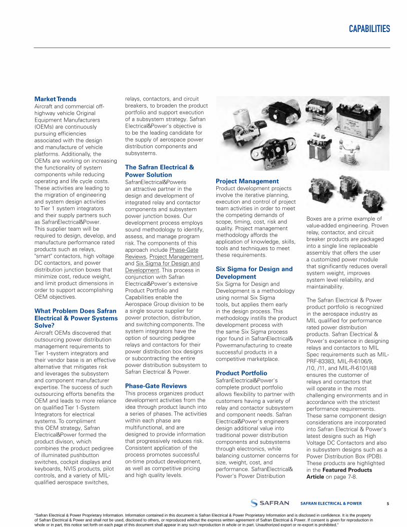
Product PortfolioSafranElectrical&Power's complete product portfolio allows flexibility to partner with customers having a variety of relay and contactor subsystem and component needs. Safran Electrical&Power's engineers design additional value into traditional power distribution components and subsystems through electronics, while balancing customer concerns for size, weight, cost, and performance. SafranElectrical& Power's Power Distribution
Boxes are a prime example of value-added engineering. Proven relay, contactor, and circuit breaker products are packaged into a single line replaceable assembly that offers the user a customized power module that significantly reduces overall system weight, improves system level reliability, and maintainability.
The Safran Electrical & Power product portfolio is recognized in the aerospace industry as MIL qualified for performance rated power distribution products. Safran Electrical & Power's experience in designing relays and contactors to MIL Spec requirements such as MIL-PRF-83383, MIL-R-6106/9, /10, /11, and MIL-R-6101/48 ensures the customer of relays and contactors that will operate in the most challenging environments and in accordance with the strictest performance requirements. These same component design considerations are incorporated into Safran Electrical & Power's latest designs such as High Voltage DC Contactors and also in subsystem designs such as a Power Distribution Box (PDB). These products are highlighted in the Featured Products Article on page 7-8.
“Safran Electrical & Power Proprietary Information. Information contained in this document is Safran Electrical & Power Proprietary Information and is disclosed in confidence. It is the property of Safran Electrical & Power and shall not be used, disclosed to others, or reproduced without the express written agreement of Safran Electrical & Power. If consent is given for reproduction in whole or in part, this notice set forth on each page of this document shall appear in any such reproduction in whole or in part. Unauthorized export or re-export is prohibited.”
LABINAL POWER SYSTEMS TF300-9E 76 SAFRAN ELECTRICAL & POWER
CAPABILITIES
The product portfolio includes:• Smart Contactors with cur rent
sensing protection, Ground Fault Interrupt technology,or Arc Fault Circuit Interrupt technology.
• 28 Vdc Contactors (50 to 1000amperes).
• 270 Vdc Contactors (25 to 350amperes).
• 115/230 Vac 400 HertzContactors (30 to430 amperes).
• 750 Vdc Contactors (100 to600 amperes).
• Power Distribution JunctionBoxes.
• A variety of aerospace switches (rocker, toggle,pushbutton and limit)
• Pilot Controls including customized flap controls, landing gear controls, throttle controls, trim controls (for mechanical pitch, roll and yaw), and fire emergency controls.
• Displays, readable in both direct sunlight and at night, including the popular Series 900 fiber optic displays,as well as displays with surfacemount devices and programmable electronic arrays.
• Keyboards that are sunlight andnight light readableand suited for virtually any application, including flight management panels, handheld data communications panels, shipboard computer control panels, fire system control panels, ground support equipment, and radar and telemetry control panels. Safran Electrical & Powerkeyboards also incorporatelogic boards, photo sensors,rotary and toggle switches, andannunciators, and havefeatures such as micro-processor interfacing andprogrammable logic control.
• NVIS products such ascockpit controls, displays andkeyboards, and illuminatedpush button switches thatconform to MIL and NVISspecifications and any uniquecustomer needs.
• Illuminated Pushbuttonswitches with a multitude ofoptions ranging from sunlightreadable, NVIS-compatible,incandescent and LEDlighting to various mountingand termination options forflexible installation and retrofitapplications.
• Electro-mechanical thermalcircuit breakers (0.5 to 300amperes) - single phase orthree phase thermally actuateddevices offered in conventionaldesign or with integratedArc Fault Circuit Interrupttechnology.
• Remote Control CircuitBreakers (5 to 125 amperes)- single phase or three-phasedevices sold separately or as asubsystem when combinedwith a necessary indicatorcontrol unit (0.5 ampere circuitbreaker).
• Electromechanical RemotePower Controllers (125 to200 amperes) - single-phasedevices sold separately or asa subsystem when combinedwith a necessary indicatorcontrol unit (0.5 ampere circuitbreaker).
Safran Electrical & Power Capabilities
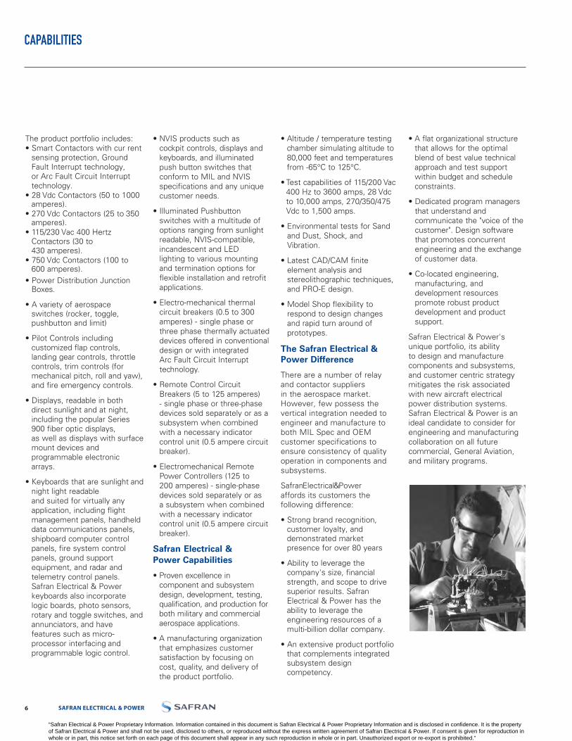
• Proven excellence incomponent and subsystemdesign, development, testing,qualification, and production forboth military and commercialaerospace applications.
• A manufacturing organizationthat emphasizes customersatisfaction by focusing oncost, quality, and delivery ofthe product portfolio.
• Altitude / temperature testingchamber simulating altitude to80,000 feet and temperaturesfrom -65°C to 125°C.
• Test capabilities of 115/200 Vac400 Hz to 3600 amps, 28 Vdcto 10,000 amps, 270/350/475Vdc to 1,500 amps.
• Environmental tests for Sandand Dust, Shock, andVibration.
• Latest CAD/CAM finiteelement analysis andstereolithographic techniques,and PRO-E design.
• Model Shop flexibility torespond to design changesand rapid turn around ofprototypes.
The Safran Electrical & Power Difference
There are a number of relay and contactor suppliers in the aerospace market. However, few possess the vertical integration needed to engineer and manufacture to both MIL Spec and OEM customer specifications to ensure consistency of quality operation in components and subsystems.
SafranElectrical&Poweraffords its customers the following difference:
• Strong brand recognition, customer loyalty, and demonstrated market presence for over 80 years
• Ability to leverage the company's size, financial strength, and scope to drivesuperior results. SafranElectrical & Power has theability to leverage theengineering resources of amulti-billion dollar company.
• An extensive product portfoliothat complements integratedsubsystem design competency.
• A flat organizational structurethat allows for the optimalblend of best value technicalapproach and test supportwithin budget and scheduleconstraints.
• Dedicated program managersthat understand andcommunicate the "voice of thecustomer". Design softwarethat promotes concurrentengineering and the exchangeof customer data.
• Co-located engineering,manufacturing, anddevelopment resourcespromote robust productdevelopment and productsupport.
Safran Electrical & Power's unique portfolio, its ability to design and manufacture components and subsystems, and customer centric strategy mitigates the risk associated with new aircraft electrical power distribution systems. Safran Electrical & Power is an ideal candidate to consider for engineering and manufacturing collaboration on all future commercial, General Aviation, and military programs.
“Safran Electrical & Power Proprietary Information. Information contained in this document is Safran Electrical & Power Proprietary Information and is disclosed in confidence. It is the property of Safran Electrical & Power and shall not be used, disclosed to others, or reproduced without the express written agreement of Safran Electrical & Power. If consent is given for reproduction in whole or in part, this notice set forth on each page of this document shall appear in any such reproduction in whole or in part. Unauthorized export or re-export is prohibited.”
SAFRAN ELECTRICAL & POWER 76 LABINAL POWER SYSTEMS TF300-9E
FEATURED PRODUCTS
Changing Aerospace IndustryIn today's consolidating aerospace industry, Tier 1-System Integrators and Airframe Manufacturersdesire more value from their component suppliers. A qualified supplier must not only havean extensive product portfolio, but must also display proven subsystem capabilities. These abilities include the capacityto design, manufacture,and test customized power distribution assemblies that consolidate multiple functions in a single package. Over the past decade, SafranElectrical& Power acknowledged this fact, and has focused its attention on developing these value-add competencies to become a recognized leader in integrated power distribution systems. Specifically, LSafranElectrical& Powerhas stayedat the forefront of product/ technology development through the development of the following components and subassemblies: High-Voltage DC (HVDC) Contactors, Next-Generation Alternating Current (AC) Contactors, and Power Distribution Boxes.
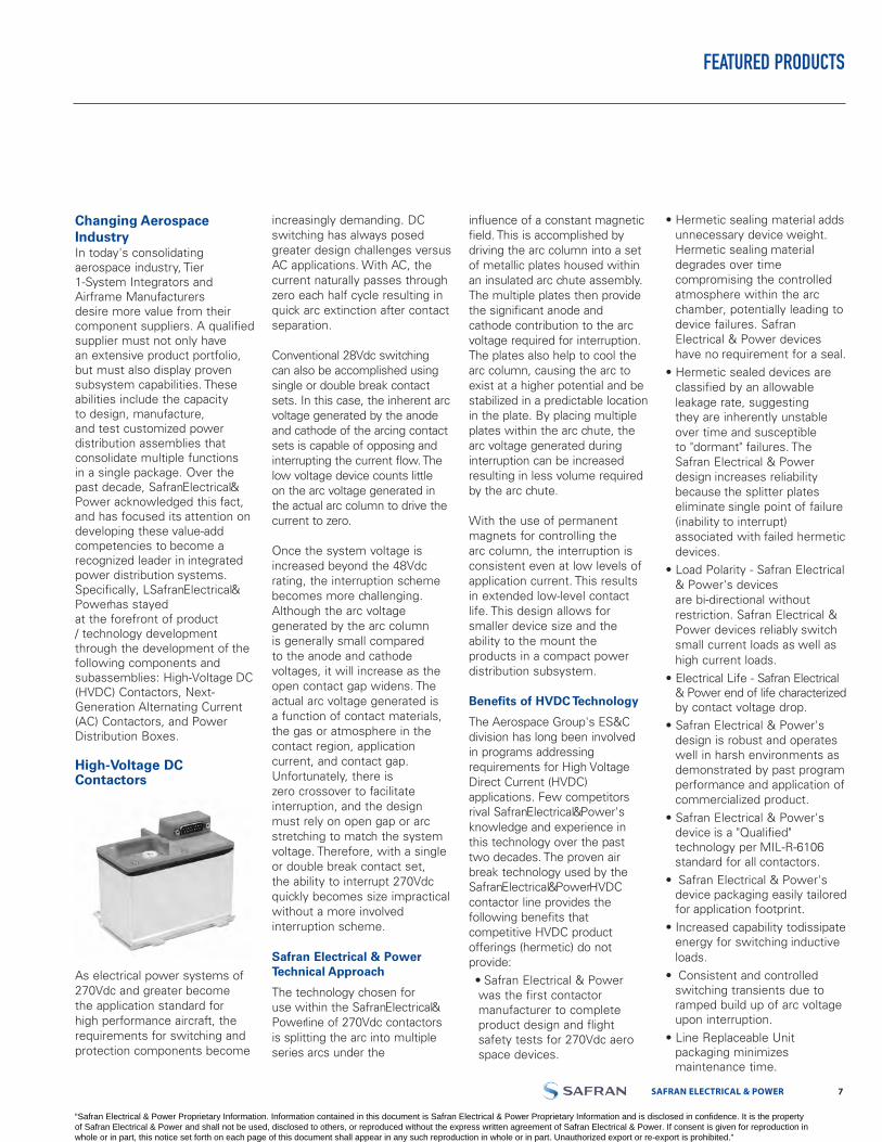
High-Voltage DC Contactors
As electrical power systems of 270Vdc and greater become the application standard for high performance aircraft, the requirements for switching and protection components become
increasingly demanding. DC switching has always posed greater design challenges versus AC applications. With AC, the current naturally passes through zero each half cycle resulting in quick arc extinction after contact separation.
Conventional 28Vdc switching can also be accomplished using single or double break contact sets. In this case, the inherent arc voltage generated by the anode and cathode of the arcing contact sets is capable of opposing and interrupting the current flow. The low voltage device counts little on the arc voltage generated in the actual arc column to drive the current to zero.
Once the system voltage is increased beyond the 48Vdc rating, the interruption scheme becomes more challenging. Although the arc voltage generated by the arc column is generally small compared to the anode and cathode voltages, it will increase as the open contact gap widens. The actual arc voltage generated is a function of contact materials, the gas or atmosphere in the contact region, application current, and contact gap. Unfortunately, there is zero crossover to facilitate interruption, and the design must rely on open gap or arc stretching to match the system voltage. Therefore, with a single or double break contact set, the ability to interrupt 270Vdc quickly becomes size impractical without a more involved interruption scheme.
Safran Electrical & Power Technical Approach
The technology chosen for use within the SafranElectrical&Powerline of 270Vdc contactors is splitting the arc into multiple series arcs under the
influence of a constant magnetic field. This is accomplished by driving the arc column into a set of metallic plates housed within an insulated arc chute assembly. The multiple plates then provide the significant anode and cathode contribution to the arc voltage required for interruption. The plates also help to cool the arc column, causing the arc to exist at a higher potential and be stabilized in a predictable location in the plate. By placing multiple plates within the arc chute, the arc voltage generated during interruption can be increased resulting in less volume required by the arc chute.
With the use of permanent magnets for controlling the arc column, the interruption is consistent even at low levels of application current. This results in extended low-level contact life. This design allows for smaller device size and the ability to the mount the products in a compact power distribution subsystem.
Benefits of HVDC Technology
The Aerospace Group's ES&C division has long been involved in programs addressing requirements for High Voltage Direct Current (HVDC) applications. Few competitors rival SafranElectrical&Power's knowledge and experience in this technology over the past two decades. The proven air break technology used by the SafranElectrical&PowerHVDC contactor line provides the following benefits that competitive HVDC product offerings (hermetic) do not provide:• Safran Electrical & Powerwas the first contactor manufacturer to complete product design and flight safety tests for 270Vdc aerospace devices.
• Hermetic sealing material addsunnecessary device weight.Hermetic sealing materialdegrades over time compromising the controlled atmosphere within the arc chamber, potentially leading to device failures. SafranElectrical & Power deviceshave no requirement for a seal.
• Hermetic sealed devices are classified by an allowable leakage rate, suggestingthey are inherently unstable over time and susceptibleto "dormant" failures. The Safran Electrical & Powerdesign increases reliabilitybecause the splitter plateseliminate single point of failure(inability to interrupt)associated with failed hermeticdevices.
• Load Polarity - Safran Electrical& Power's devicesare bi-directional without restriction. Safran Electrical &Power devices reliably switchsmall current loads as well ashigh current loads.
• Electrical Life - Safran Electrical & Power end of life characterizedby contact voltage drop.
• Safran Electrical & Power's design is robust and operates well in harsh environments as demonstrated by past programperformance and application ofcommercialized product.
• Safran Electrical & Power'sdevice is a "Qualified"technology per MIL-R-6106standard for all contactors.
• Safran Electrical & Power'sdevice packaging easily tailoredfor application footprint.
• Increased capability to dissipateenergy for switching inductiveloads.
• Consistent and controlled switching transients due to ramped build up of arc voltageupon interruption.
• Line Replaceable Unit packaging minimizes maintenance time.
“Safran Electrical & Power Proprietary Information. Information contained in this document is Safran Electrical & Power Proprietary Information and is disclosed in confidence. It is the property of Safran Electrical & Power and shall not be used, disclosed to others, or reproduced without the express written agreement of Safran Electrical & Power. If consent is given for reproduction in whole or in part, this notice set forth on each page of this document shall appear in any such reproduction in whole or in part. Unauthorized export or re-export is prohibited.”
LABINAL POWER SYSTEMS TF300-9E 98 SAFRAN ELECTRICAL & POWER
The SafranElectrical&Power design does not require a hermetic seal, providing several advantages in application. In military applications, the use of splitter plate technology allows the device to function reliably throughout the life of the airframe while being subjected to harsh combat field environments and flight profiles that involve extreme levels of vibration and shock that can compromise competitors' hermetic seal product designs. The loss of a hermetic seal causes device failure as it relies on the sealed atmosphere within the device to interrupt high voltage. A failure of this nature could cause mission cancellation, mission abort, or even loss of aircraft. If installed in commercial aircraft applications, hermetically sealed devices would require periodic maintenance crew checks to prevent the risk of "dormant" failures associated with this design. The SafranElectrical&Power design reduces/eliminates the need for maintenance involvement and better supports Air Carrier objectives for maintenance-free devices.
Combining ongoing research with current product development, SafranElectrical&Powercontinually strives to be a premier supplier of High-Voltage DC components and subsystems.
Next Generation Contactors
SafranElectrical&Powerhas extensive experience in the research, design, and development of various AC Contactor product lines, including "Smart" contactors with integrated current sensing and Arc Fault Circuit interrupt (AFCI) technology, 28Vdc Lightweight
Contactors, and Advanced Generator Contactors.
"Smart" ContactorsSafranElectrical&Poweris currently developing 175/60 amp packages for galleys, pumps, and primary load distribution. These contactors use the latest technologies, and can include current sensors for overcurrent protection and/or AFCI sensing. Internal / centralized electronics control are also features of these devices. SafranElectrical&Power is continually looking for lower weight / size product solutions; a prime example being the 60 amp "Smart" contactor that is currently no bigger than a SafranElectrical&Power3-phase motor circuit protection device.
28Vdc Lightweight Contactors SafranElectrical&Poweris also developing a new 28Vdc, 50-400 Amp contactor family whose focus is on the reduction of weight and cost. Bolt-on designs combine power terminations and mechanical mounting, and contain captive hardware for all mounting fasteners. Both Single Pole Single Throw and Single Pole Double Throw configurations are available with features such as SubD or sealed in-line connectors.
Advanced Generator Contactors
Based upon the existing SM15 product line, a new AC Generator contactor line of products is emerging. These contactors have automatic control connector
mating and either Three Pole Single Throw or Three Pole Double Throw main contacts. SafranElectrical&Poweroffers 115 VAC or 230 VAC (350-800Hz) generator contactors that are bolt-on designs with SubD connectors and rated at either 260 amps or 430 amps. They are currently one of the smallest and lightest AC contactors in the aerospace generator relay market, accommodate Variable Frequency and double voltage aircraft architectures, and are suitable for either stand-alone applications or power distribution boxes.
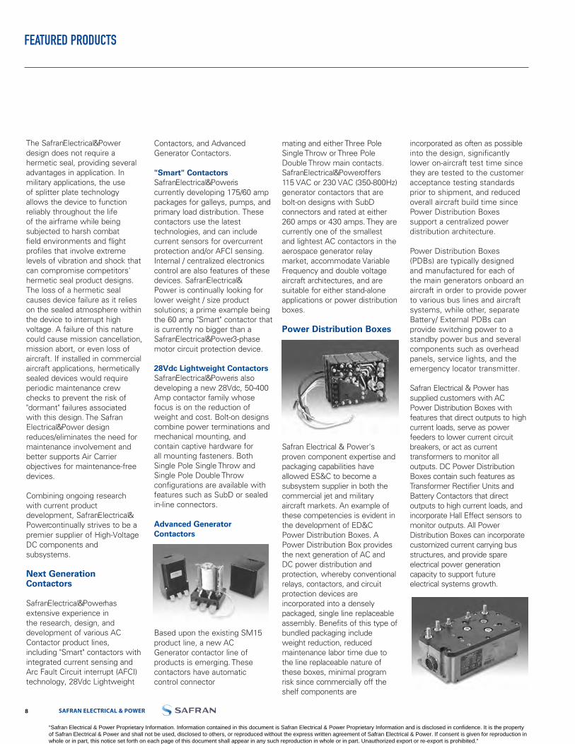
Power Distribution Boxes
Safran Electrical & Power's proven component expertise and packaging capabilities have allowed ES&C to become a subsystem supplier in both the commercial jet and military aircraft markets. An example of these competencies is evident in the development of ED&C Power Distribution Boxes. A Power Distribution Box provides the next generation of AC and DC power distribution and protection, whereby conventional relays, contactors, and circuit protection devices are incorporated into a densely packaged, single line replaceable assembly. Benefits of this type of bundled packaging include weight reduction, reduced maintenance labor time due to the line replaceable nature of these boxes, minimal program risk since commercially off the shelf components are
incorporated as often as possible into the design, significantly lower on-aircraft test time since they are tested to the customer acceptance testing standards prior to shipment, and reduced overall aircraft build time since Power Distribution Boxes support a centralized power distribution architecture.
Power Distribution Boxes (PDBs) are typically designed and manufactured for each of the main generators onboard an aircraft in order to provide power to various bus lines and aircraft systems, while other, separate Battery/ External PDBs can provide switching power to a standby power bus and several components such as overhead panels, service lights, and the emergency locator transmitter.
Safran Electrical & Power has supplied customers with AC Power Distribution Boxes with features that direct outputs to high current loads, serve as power feeders to lower current circuit breakers, or act as current transformers to monitor all outputs. DC Power Distribution Boxes contain such features as Transformer Rectifier Units and Battery Contactors that direct outputs to high current loads, and incorporate Hall Effect sensors to monitor outputs. All Power Distribution Boxes can incorporate customized current carrying bus structures, and provide spare electrical power generation capacity to support future electrical systems growth.
FEATURED PRODUCTS
“Safran Electrical & Power Proprietary Information. Information contained in this document is Safran Electrical & Power Proprietary Information and is disclosed in confidence. It is the property of Safran Electrical & Power and shall not be used, disclosed to others, or reproduced without the express written agreement of Safran Electrical & Power. If consent is given for reproduction in whole or in part, this notice set forth on each page of this document shall appear in any such reproduction in whole or in part. Unauthorized export or re-export is prohibited.”

SAFRAN ELECTRICAL & POWER 98 LABINAL POWER SYSTEMS TF300-9E
REMOTE CONTROLLED CIRCUIT BREAKER (RCCB)
Qualified
Qualified to demanding perfor-mance parameters of MIL- PRF - 83383 standard.
Use as a Relay, Circuit Breaker, Or Both
RCCBs combine the best attri-butes of a circuit breaker and a relay. Automatically protects the wires and the load device dur-ing circuit/load breakdown, but allows the flight deck control of the load during normal opera-tion.
Weight and Cost Savings
In distributed-load applications, RCCBs are a more efficient power distribution solution pro-moting cost and weight savings through the elimination of long runs of heavy cables associ-ated with the conventional relay - flight deck circuit protectormethod. Control of the RCCB requires only one #22 AWG control wire from the ICU on the flight deck to the RCCB.
Cockpit Space Savings
An RCCB system removes the presence of large circuit break-ers from the cockpit while per-mitting remote On/Off operation from the flight deck. Combine Safran Electrical & Power RCCB with Indicator Control Unit (ICU) model #1500-052-05.
OVERLOAD CALIBRATION DATA
Specification Table
Must HoldMust Trip
MIN
115%
@ 25°C
MAX
138%
@ +71°C
MIN
115%
MAX
138%
@ -54°C
MIN
115%
MAX
150%
Test Time Parameters% for 1 Hour
% Within 1 Hour
Single Pole• 28 VDC• 115/200 VAC 400 Hz
Three Phase• 115/200 VAC 400 Hz• Three Phase Only
Rupture Levels 3600 A (115 VAC or 28VDC for 1 Pole and 115VAC for 3 Pole)
Endurance 50,000 Cycles(Resistive & Inductive (Motor) Endurance (Motor) 5-50A: 50,000 cycles; 60-100A: 25,000 cyclesEndurance (Lamp) 5-25A: 50,000 cycles; 35-50A: 25,000 cycles; 60-100A: no ratingDielectric Strength 1500V, 60 Hz, MIL-STD-202, method 301, 0.5 MA maxInsulation Resistance 100 mega ohm min, MIL-STD-202, method 302Thermal Temperature Range -54°C to 71°C (-65°F to 160°F). MIL-STD-202, Method 107
Vibration 10G's to 2000 Hz. Exceeds MIL-STD-202, Method 204, Condition C, 10 microseconds max. chatter
Shock 25G's. MIL-STD-202, Method 213, 10 microseconds max. chatter Altitude 50,000 ft.
EMI Requirements MIL-STD-461, Requirements CS114 and RE102 over the frequency range of 14 kHz to 400 MHz and RE102 limits for Aircraft and Space Systems.
EMI/RFI Susceptibility MIL-STD-461, Class 1D and GenerationMoisture Resistance MIL-STD-202, method 106Salt Spray Resistance MIL-STD-202, method 101, Condition BSand and Dust Resistance MIL-STD-202, method 110, Condition AFungus Resistance MIL-HDBK-454, Guideline 4Explosion Proof MIL-STD-202, method 109
Weight (Single Pole) 5-25A: 318 grams (0.703 lbs.); 35-50A: 325 grams (0.719 lbs.); 60-100A: 332 grams (0.734 lbs.)
Weight (w/ Auxiliary Contacts) 5-25A: 332 grams (0.734 lbs.); 35-50A: 339 grams (0.750 lbs.); 60-100A: 346 grams (0.766 lbs.)
Weight (Three Phase) 2.0 lbs. max.
PERFORMANCE DATA
“Safran Electrical & Power Proprietary Information. Information contained in this document is Safran Electrical & Power Proprietary Information and is disclosed in confidence. It is the property of Safran Electrical & Power and shall not be used, disclosed to others, or reproduced without the express written agreement of Safran Electrical & Power. If consent is given for reproduction in whole or in part, this notice set forth on each page of this document shall appear in any such reproduction in whole or in part. Unauthorized export or re-export is prohibited.”

LABINAL POWER SYSTEMS TF300-9E 1110 SAFRAN ELECTRICAL & POWER
REMOTE CONTROLLED CIRCUIT BREAKER (RCCB)
Three Pole Single Throw (Double Break Contacts)
CatalogNumber
Rated Contact Load(Amperes)
115/200 V 400 HzMIL-PRF-83383 Part NumberRes. Ind. Motor Lamp
SM601BA10A1 10 10 10 10 M83383/04-03
SM601BA15A1 15 15 15 15
SM601BA20A1 20 20 20 20 M83383/04-05
SM601BA25A1 25 25 25 25
SM601BA35A1 35 35 35 35 M83383/04-07
SM601BA40A1 40 40 40 40 M83383/04-08
SM601BA50A1 50 50 50 50
SM601BA60A1 60 60 60 60 M83383/04-10
Contact factory on alternate amperage, trip times, control configurations, grounding, auxiliary switches, and mounting systems.
Engineering Data
Single Pole Single Throw (Double Break Contacts)
Catalog Number
Rated Contact Load (Amperes)
MIL-PRF-83383 Part Number
Maximum Weight Oz/gm
28 Vdc 115/200 V 400 Hz
Res. Ind. Motor Lamp Res. Ind. Motor Lamp
SM600BA5A1 5 5 5 5 5 5 5 5 M83383/02-01 11.75/332
SM600BA5N1
10 10 10 10 10 10 10 10
M83383/01-02 11.25/318SM600BA10A1 M83383/02-03 11.75/332SM600BA10N1
15 15 15 15 15 15 15 15
M83383/01-03 11.25/318SM600BA15A1 M83383/02-04 11.75/332SM600BA15N1
20 20 20 20 20 20 20 20
M83383/01-04 11.25/318SM600BA20A1 M83383/02-05 11.75/332SM600BA20N1
25 25 25 25 25 25 25 25
M83383/01-05 11.25/318SM600BA25A1 M83383/02-06 11.75/332SM600BA25N1
35 35 35 35 35 35 35 35
M83383/01-06 11.25/318SM600BA35A1 M83383/02-07 12.00/339SM600BA35N1
40 40 40 40 40 40 40 40
M83383/01-07 11.50/325SM600BA40A1 M83383/02-08 12.00/339SM600BA40N1
50 50 50 50 50 50 50 50
M83383/01-08 11.50/325SM600BA50A1 M83383/02-09 12.00/339SM600BA50N1
60 60 60 — 60 60 60 —
M83383/01-09 11.50/325SM600BA60A1 M8338/02-10 12.25/346SM600BA60N1
75 75 75 — 75 75 75 —
M83383/01-10 11.75/332SM600BA75A1 M83383/02-11 12.25/346SM600BA75N1
100 100 100 — 100 100 100 —M83383/01-11 11.75/332
SM600BA100A1 M83383/02-13 12.25/346SM600BA100N1 M83383/01-13 11.75/332
“Safran Electrical & Power Proprietary Information. Information contained in this document is Safran Electrical & Power Proprietary Information and is disclosed in confidence. It is the property of Safran Electrical & Power and shall not be used, disclosed to others, or reproduced without the express written agreement of Safran Electrical & Power. If consent is given for reproduction in whole or in part, this notice set forth on each page of this document shall appear in any such reproduction in whole or in part. Unauthorized export or re-export is prohibited.”
SAFRAN ELECTRICAL & POWER 1110 LABINAL POWER SYSTEMS TF300-9E
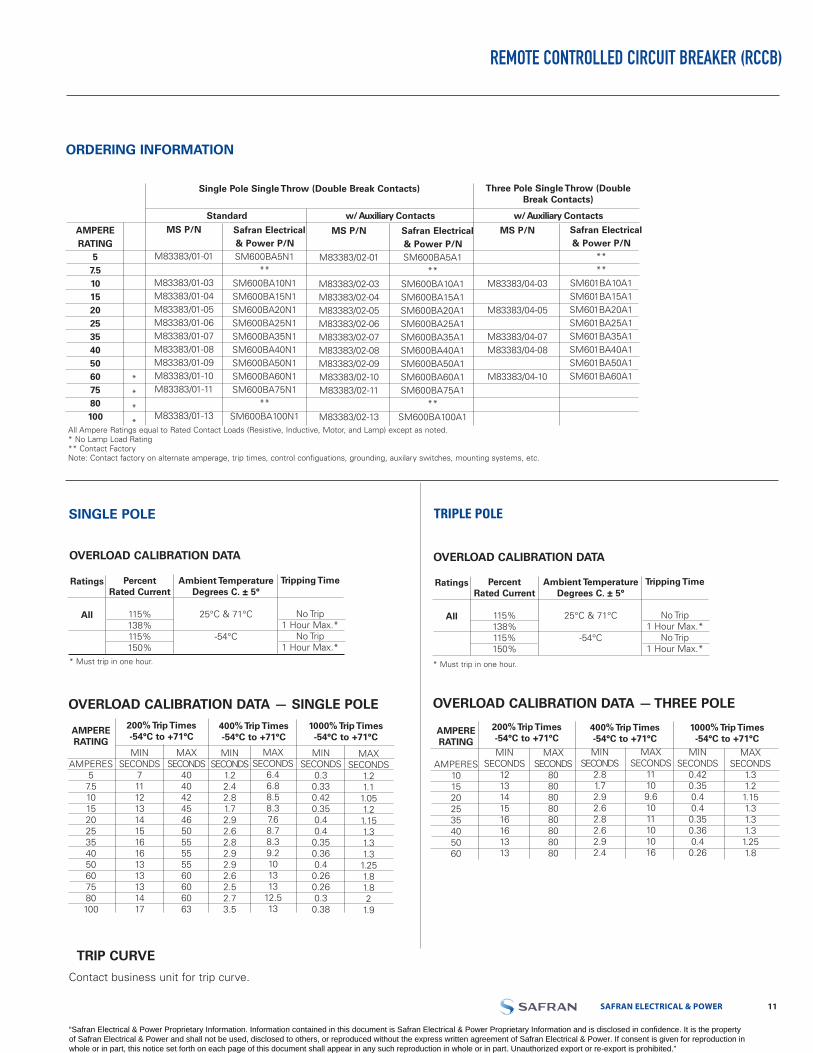
ORDERING INFORMATION
REMOTE CONTROLLED CIRCUIT BREAKER (RCCB)
OVERLOAD CALIBRATION DATA
Ratings
All
PercentRated Current
115%138%115%150%
Ambient Temperature Degrees C. ± 5°
25°C & 71°C
-54°C
Tripping Time
No Trip1 Hour Max.*
No Trip1 Hour Max.*
* Must trip in one hour.
SINGLE POLE
OVERLOAD CALIBRATION DATA
Ratings
All
PercentRated Current
115%138%115%150%
Ambient Temperature Degrees C. ± 5°
25°C & 71°C
-54°C
Tripping Time
No Trip1 Hour Max.*
No Trip1 Hour Max.*
* Must trip in one hour.
TRIPLE POLE
TRIP CURVE
Contact business unit for trip curve.
AMPERE RATING
AMPERES5
7.510152025354050607580100
MINSECONDS
7111213141516161313131417
200% Trip Times-54°C to +71°C
MAXSECONDS
40404245465055555560606063
400% Trip Times-54°C to +71°C
MIN SECONDS
1.22.42.81.72.92.62.82.92.92.62.52.73.5
MAXSECONDS
6.46.88.58.37.68.78.39.2101313
12.513
1000% Trip Times-54°C to +71°C
MINSECONDS
0.30.330.420.350.40.40.350.360.40.260.260.30.38
MAXSECONDS
1.21.1
1.051.21.151.31.31.3
1.251.81.82
1.9
OVERLOAD CALIBRATION DATA — SINGLE POLE
AMPERE RATING
57.510152025354050607580100
MS P/N
M83383/01-01
M83383/01-03M83383/01-04M83383/01-05M83383/01-06M83383/01-07M83383/01-08M83383/01-09M83383/01-10M83383/01-11
M83383/01-13
Single Pole Single Throw (Double Break Contacts) Three Pole Single Throw (Double Break Contacts)
Standard w/ Auxiliary Contacts w/ Auxiliary Contacts
*
*
*
*
Safran Electrical & Power P/NSM600BA5N1
**SM600BA10N1SM600BA15N1SM600BA20N1SM600BA25N1SM600BA35N1SM600BA40N1SM600BA50N1SM600BA60N1SM600BA75N1
**SM600BA100N1
MS P/N
M83383/02-01
M83383/02-03M83383/02-04M83383/02-05M83383/02-06M83383/02-07M83383/02-08M83383/02-09M83383/02-10M83383/02-11
M83383/02-13
Safran Electrical & Power P/NSM600BA5A1
**SM600BA10A1SM600BA15A1SM600BA20A1SM600BA25A1SM600BA35A1SM600BA40A1SM600BA50A1SM600BA60A1SM600BA75A1
**SM600BA100A1
MS P/N
M83383/04-03
M83383/04-05
M83383/04-07M83383/04-08
M83383/04-10
Safran Electrical & Power P/N
****
SM601BA10A1SM601BA15A1SM601BA20A1SM601BA25A1SM601BA35A1SM601BA40A1SM601BA50A1SM601BA60A1
All Ampere Ratings equal to Rated Contact Loads (Resistive, Inductive, Motor, and Lamp) except as noted.* No Lamp Load Rating ** Contact FactoryNote: Contact factory on alternate amperage, trip times, control configuations, grounding, auxilary switches, mounting systems, etc.
AMPERE RATING
AMPERES1015202535405060
MINSECONDS
1213141516161313
200% Trip Times-54°C to +71°C
MAXSECONDS
8080808080808080
400% Trip Times-54°C to +71°CMIN
SECONDS2.81.72.92.62.82.62.92.4
MAXSECONDS
11109.61011101016
1000% Trip Times-54°C to +71°C
MINSECONDS
0.420.350.40.40.350.360.40.26
MAXSECONDS
1.31.21.151.31.31.31.251.8
OVERLOAD CALIBRATION DATA — THREE POLE
“Safran Electrical & Power Proprietary Information. Information contained in this document is Safran Electrical & Power Proprietary Information and is disclosed in confidence. It is the property of Safran Electrical & Power and shall not be used, disclosed to others, or reproduced without the express written agreement of Safran Electrical & Power. If consent is given for reproduction in whole or in part, this notice set forth on each page of this document shall appear in any such reproduction in whole or in part. Unauthorized export or re-export is prohibited.”
LABINAL POWER SYSTEMS TF300-9E 1312 SAFRAN ELECTRICAL & POWER
REMOTE CONTROLLED CIRCUIT BREAKER (RCCB)
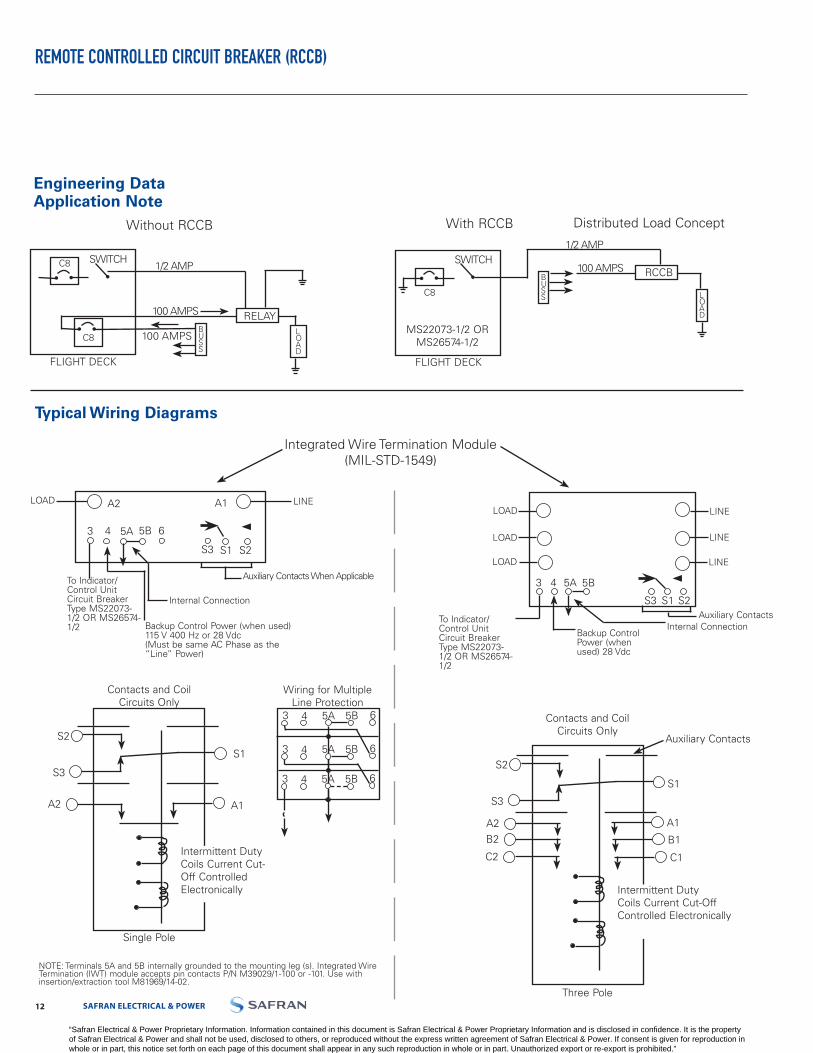
Engineering Data Application Note
C8
FLIGHT DECK
SWITCH
MS22073-1/2 ORMS26574-1/2
BUSS L
OAD
1/2 AMP
100 AMPS RCCB
With RCCB Distributed Load Concept
Typical Wiring Diagrams
NOTE: Terminals 5A and 5B internally grounded to the mounting leg (s). Integrated Wire Termination (IWT) module accepts pin contacts P/N M39029/1-100 or -101. Use with insertion/extraction tool M81969/14-02.
Contacts and Coil Circuits Only
S2
S3
Three Pole
A2
Auxiliary Contacts
S1
Intermittent Duty Coils Current Cut-Off Controlled Electronically
B2
C2
A1
B1
C1
Contacts and Coil Circuits Only
S2
S3
A2
S1
A1
Single Pole
Intermittent Duty Coils Current Cut-Off Controlled Electronically
Without RCCB
C8
C8BUSS
FLIGHT DECK
100 AMPS
RELAY
SWITCH1/2 AMP
100 AMPS
LOAD
Integrated Wire Termination Module(MIL-STD-1549)
5A 5B
S3 S1 S2
A1A2
To Indicator/Control Unit Circuit Breaker Type MS22073-1/2 OR MS26574-1/2 Backup Control Power (when used)
115 V 400 Hz or 28 Vdc(Must be same AC Phase as the “Line” Power)
Internal Connection
Auxiliary Contacts When Applicable
LINELOAD
3 4 6
LOAD
LOAD
LOAD
LINE
LINE
LINE
To Indicator/Control Unit Circuit Breaker Type MS22073-1/2 OR MS26574-1/2
5A 5B
S3 S1 S2
Backup Control Power (when used) 28 Vdc
Internal ConnectionAuxiliary Contacts
3 4
Wiring for Multiple Line Protection
3 4 5A 65B
3 4 5A 65B
3 4 5A 65B
“Safran Electrical & Power Proprietary Information. Information contained in this document is Safran Electrical & Power Proprietary Information and is disclosed in confidence. It is the property of Safran Electrical & Power and shall not be used, disclosed to others, or reproduced without the express written agreement of Safran Electrical & Power. If consent is given for reproduction in whole or in part, this notice set forth on each page of this document shall appear in any such reproduction in whole or in part. Unauthorized export or re-export is prohibited.”

SAFRAN ELECTRICAL & POWER 1312 LABINAL POWER SYSTEMS TF300-9E
REMOTE CONTROLLED CIRCUIT BREAKER (RCCB) — 1 POLE AND 3 POLE
Engineering Data
Approximate Dimensions - 1 Pole
Options• Special application auxiliary
switches• Unique grounding• Power sources• Other current ratings• Control via systems other
than I/CU• Low level auxiliary contacts
available• Data Bus/Interface capability
available• Electronically held coil• Moisture resistant sealing
Three Pole
Typical Placement of Rating on Top Plane
LOA
D A
2
LIN
E A
1
50
.172/4.37 DIA.2 MTG. HOLESR. 20
5.08
.688/17.48
2.94074.68
3.25082.55
Main ContactPosition Indicator
Red: Closed; Green: Open
Mtg. FlangesMate As Shown
1.53038.86
2.25057.15 .350
8.89 .071.778
.500 - .61012.70 - 15.24
.1804.57
3.4286.87
Name Plate
.0842.13
4.26108.20
.0561.42
.4210.67
1.20030.48
LOA
D A
2LO
AD
B2
LOA
D C
2
LIN
E A
1LI
NE
B1
LIN
E C
1
50
2.52664.16
2.94074.68
3.25082.55
2.52664.16
Main Contact Position Indicator
Red: Closed; Green: Open
2.2857.91
1.5038.86
.3508.89
.071.78
.051.27
4.26108.20
3.4387.12
.1303.30
.7719.56
2.0351.56
3.2983.57
3.6993.73
Location of NamePlate
Coil Operate Current/Set And Trip Time RCCB
Circuits
1 Pole
3 Pole
Nominal System Voltage
28 Vdc(18 volts MIN.)
115 Vac400 Hz (104 V.
MIN.28 Vdc
(18 volts MIN.)115 Vac
400 Hz (104 V. MIN.)
I/CU Set Current @ Nom Voltage
(Mulliamp)
2
2
2
2
Set Coil Current @ Nom Voltage Pulse
3.0 AMP MAX
10 AMPMAX
7.0 AMPMAX
13.0 AMPMAX
Nominal Voltage &
Room Temp.
20 Millisec
15 Millisec
20 Millisec
15 Millisec
MAX. Set TimeMost Adverse
Condition - MIN. Voltage 71°C.
Ambient
35 Millisec
30 Millisec
35 Millisec
30 Millisec
*I/CU. Trip Current Nominal71°C &
Nominal Voltage
1.4 AMP
6.8 AMP**
1.5 AMP
4.3 AMP**
-54°C &Nominal Voltage
1.9 AMP
6.3 AMP**
2.0 AMP
3.3 AMP**
Room Temp. Nominal Voltage
1.6 AMP
8.6 AMP**
1.7 AMP
4.5 AMP**
71°C & Nominal Voltage
0.9 AMP***
6.1 AMP**
0.9 AMP***
4.0 AMP**
-54°C &Nominal Voltage
2.1 AMP
7.0 AMP**
2.2 AMP
3.1 AMP**
MAX. Standby Current
Milliamp
10
10
10
10
* MAX. I/CU. Line Impedance 7.5 Current Decreases w/Time so that I2t** Average Half-Wave Rectified DC Current ***Absolute Min. Value from -54° to +71°C
“Safran Electrical & Power Proprietary Information. Information contained in this document is Safran Electrical & Power Proprietary Information and is disclosed in confidence. It is the property of Safran Electrical & Power and shall not be used, disclosed to others, or reproduced without the express written agreement of Safran Electrical & Power. If consent is given for reproduction in whole or in part, this notice set forth on each page of this document shall appear in any such reproduction in whole or in part. Unauthorized export or re-export is prohibited.”
LABINAL POWER SYSTEMS TF300-9E 1514 SAFRAN ELECTRICAL & POWER
• Fusible link fail safe
• Remote on/off operation fromthe flight deck
• Visual indicators for open(green) and closed (red) ontop surface
• Substantial reduction inweight and size
• Most direct route from powersource to load
• Single wire control line fromI/CU to RCCB
• Double-break power contactassembly
• Indication of trip or set byposition of the ½ ampere circuitbreaker on the flight deck
• Elimination of long runs ofheavy and costly cables
• Magnetically latched coils(low power consumption)
• Use as a relay or circuitbreaker or both
• Flanges mate for in-line orside-by-side mounting
• 1PST for DC or single phase AC
• 3PST for three phase AC only
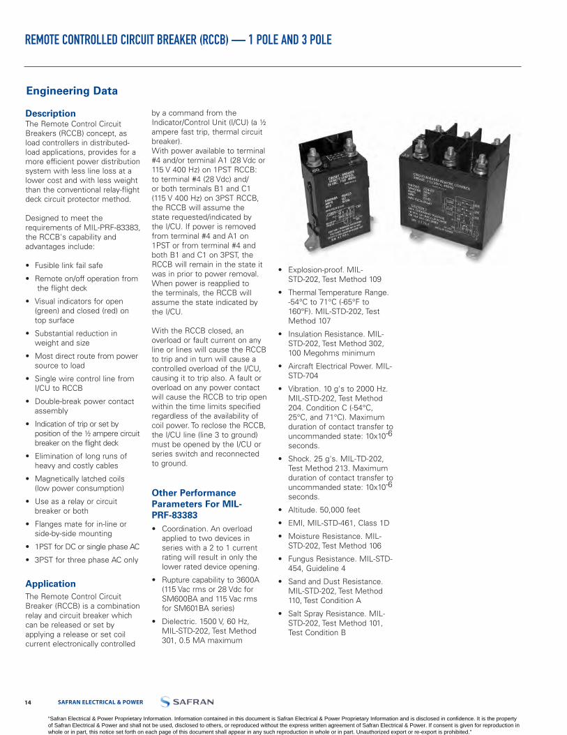
ApplicationThe Remote Control Circuit Breaker (RCCB) is a combination relay and circuit breaker which can be released or set by applying a release or set coil current electronically controlled
by a command from the Indicator/Control Unit (I/CU) (a ½ ampere fast trip, thermal circuit breaker).With power available to terminal #4 and/or terminal A1 (28 Vdc or 115 V 400 Hz) on 1PST RCCB: to terminal #4 (28 Vdc) and/or both terminals B1 and C1 (115 V 400 Hz) on 3PST RCCB, the RCCB will assume the state requested/indicated by the I/CU. If power is removed from terminal #4 and A1 on 1PST or from terminal #4 and both B1 and C1 on 3PST, the RCCB will remain in the state it was in prior to power removal. When power is reapplied to the terminals, the RCCB will assume the state indicated by the I/CU.
With the RCCB closed, an overload or fault current on any line or lines will cause the RCCB to trip and in turn will cause a controlled overload of the I/CU, causing it to trip also. A fault or overload on any power contact will cause the RCCB to trip open within the time limits specified regardless of the availability of coil power. To reclose the RCCB, the I/CU line (line 3 to ground) must be opened by the I/CU or series switch and reconnected to ground.
Other Performance Parameters For MIL-PRF-83383• Coordination. An overload
applied to two devices inseries with a 2 to 1 currentrating will result in only thelower rated device opening.
• Rupture capability to 3600A(115 Vac rms or 28 Vdc forSM600BA and 115 Vac rmsfor SM601BA series)
• Dielectric. 1500 V, 60 Hz,MIL-STD-202, Test Method 301, 0.5 MA maximum
• Explosion-proof. MIL-STD-202, Test Method 109
• Thermal Temperature Range. -54°C to 71°C (-65°F to160°F). MIL-STD-202, Test Method 107
• Insulation Resistance. MIL- STD-202, Test Method 302,100 Megohms minimum
• Aircraft Electrical Power. MIL- STD-704
• Vibration. 10 g's to 2000 Hz.MIL-STD-202, Test Method204. Condition C (-54°C,25°C, and 71°C). Maximumduration of contact transfer touncommanded state: 10x10-6
seconds.
• Shock. 25 g's. MIL-TD-202,Test Method 213. Maximumduration of contact transfer touncommanded state: 10x10-6
seconds.
• Altitude. 50,000 feet
• EMI, MIL-STD-461, Class 1D
• Moisture Resistance. MIL- STD-202, Test Method 106
• Fungus Resistance. MIL-STD-454, Guideline 4
• Sand and Dust Resistance.MIL-STD-202, Test Method110, Test Condition A
• Salt Spray Resistance. MIL- STD-202, Test Method 101,Test Condition B
REMOTE CONTROLLED CIRCUIT BREAKER (RCCB) — 1 POLE AND 3 POLE
Engineering Data
DescriptionThe Remote Control Circuit Breakers (RCCB) concept, as load controllers in distributed-load applications, provides for a more efficient power distribution system with less line loss at a lower cost and with less weight than the conventional relay-flight deck circuit protector method.
Designed to meet the requirements of MIL-PRF-83383, the RCCB's capability and advantages include:
“Safran Electrical & Power Proprietary Information. Information contained in this document is Safran Electrical & Power Proprietary Information and is disclosed in confidence. It is the property of Safran Electrical & Power and shall not be used, disclosed to others, or reproduced without the express written agreement of Safran Electrical & Power. If consent is given for reproduction in whole or in part, this notice set forth on each page of this document shall appear in any such reproduction in whole or in part. Unauthorized export or re-export is prohibited.”
1514 LABINAL POWER SYSTEMS TF300-9E
REMOTE CONTROLLED CIRCUIT BREAKER (RCCB)
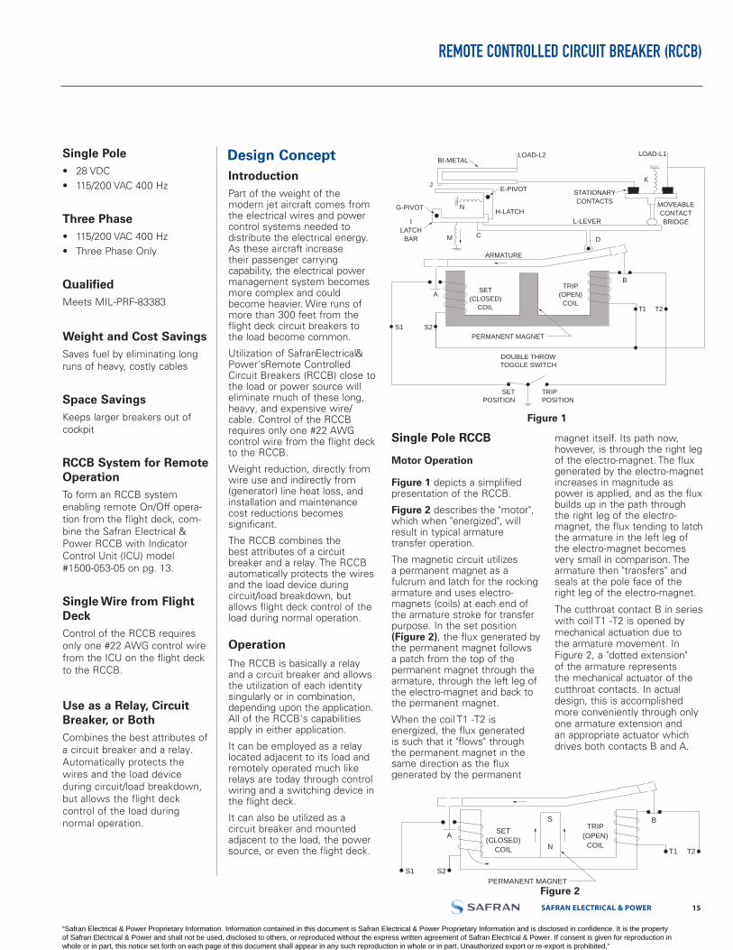
Single Pole RCCB
Motor Operation
Figure 1 depicts a simplified presentation of the RCCB.
Figure 2 describes the "motor", which when "energized", will result in typical armature transfer operation.
The magnetic circuit utilizes a permanent magnet as a fulcrum and latch for the rocking armature and uses electro-magnets (coils) at each end of the armature stroke for transfer purpose. In the set position (Figure 2), the flux generated by the permanent magnet follows a patch from the top of the permanent magnet through the armature, through the left leg of the electro-magnet and back to the permanent magnet.
When the coil T1 -T2 is energized, the flux generated is such that it "flows" through the permanent magnet in the same direction as the flux generated by the permanent
magnet itself. Its path now, however, is through the right leg of the electro-magnet. The flux generated by the electro-magnet increases in magnitude as power is applied, and as the flux builds up in the path through the right leg of the electro-magnet, the flux tending to latch the armature in the left leg ofthe electro-magnet becomes very small in comparison. The armature then "transfers" and seals at the pole face of the right leg of the electro-magnet.
The cutthroat contact B in series with coil T1 -T2 is opened by mechanical actuation due to the armature movement. In Figure 2, a "dotted extension" of the armature represents the mechanical actuator of the cutthroat contacts. In actual design, this is accomplished more conveniently through only one armature extension and an appropriate actuator which drives both contacts B and A.
Single Pole• 28 VDC• 115/200 VAC 400 Hz
Three Phase• 115/200 VAC 400 Hz• Three Phase Only
QualifiedMeets MIL-PRF-83383
Weight and Cost SavingsSaves fuel by eliminating long runs of heavy, costly cables
Space SavingsKeeps larger breakers out of cockpit
RCCB System for Remote OperationTo form an RCCB system enabling remote On/Off opera-tion from the flight deck, com-bine the Safran Electrical & Power RCCB with Indicator Control Unit (ICU) model #1500-053-05 on pg. 13.
Single Wire from Flight DeckControl of the RCCB requires only one #22 AWG control wire from the ICU on the flight deck to the RCCB.
Use as a Relay, Circuit Breaker, or BothCombines the best attributes of a circuit breaker and a relay. Automatically protects the wires and the load device during circuit/load breakdown, but allows the flight deck control of the load during normal operation.
Design ConceptIntroductionPart of the weight of the modern jet aircraft comes from the electrical wires and power control systems needed to distribute the electrical energy. As these aircraft increase their passenger carrying capability, the electrical power management system becomes more complex and could become heavier. Wire runs of more than 300 feet from the flight deck circuit breakers to the load become common.
Utilization of SafranElectrical&Power'sRemote Controlled Circuit Breakers (RCCB) close to the load or power source will eliminate much of these long, heavy, and expensive wire/cable. Control of the RCCB requires only one #22 AWG control wire from the flight deck to the RCCB.
Weight reduction, directly from wire use and indirectly from (generator) line heat loss, and installation and maintenance cost reductions becomes significant.
The RCCB combines the best attributes of a circuit breaker and a relay. The RCCB automatically protects the wires and the load device during circuit/load breakdown, but allows flight deck control of the load during normal operation.
Operation
The RCCB is basically a relay and a circuit breaker and allows the utilization of each identity singularly or in combination, depending upon the application. All of the RCCB's capabilities apply in either application.
It can be employed as a relay located adjacent to its load and remotely operated much like relays are today through control wiring and a switching device in the flight deck.
It can also be utilized as a circuit breaker and mounted adjacent to the load, the power source, or even the flight deck.
BI-METAL
E-PIVOT
H-LATCHG-PIVOT
LOAD-L2 LOAD-L1
K
B
D
A
S1 S2
M
N
J
T2T1
L-LEVER
ARMATURE
PERMANENT MAGNET
DOUBLE THROWTOGGLE SWITCH
SETPOSITION
TRIPPOSITION
STATIONARYCONTACTS
ILATCH
BAR
MOVEABLE CONTACT BRIDGE
TRIP(OPEN)
COIL
SET(CLOSED)
COIL
C
BS
NA
S1 S2
T2T1
PERMANENT MAGNET
TRIP(OPEN)
COIL
SET(CLOSED)
COIL
Figure 1BI-METAL
E-PIVOT
H-LATCHG-PIVOT
LOAD-L2 LOAD-L1
K
B
D
A
S1 S2
M
N
J
T2T1
L-LEVER
ARMATURE
PERMANENT MAGNET
DOUBLE THROWTOGGLE SWITCH
SETPOSITION
TRIPPOSITION
STATIONARYCONTACTS
ILATCH
BAR
MOVEABLE CONTACTBRIDGE
TRIP(OPEN)
COIL
SET(CLOSED)
COIL
C
BS
NA
S1 S2
T2T1
PERMANENT MAGNET
TRIP(OPEN)
COIL
SET(CLOSED)
COIL
Figure 2
SAFRAN ELECTRICAL & POWER
“Safran Electrical & Power Proprietary Information. Information contained in this document is Safran Electrical & Power Proprietary Information and is disclosed in confidence. It is the property of Safran Electrical & Power and shall not be used, disclosed to others, or reproduced without the express written agreement of Safran Electrical & Power. If consent is given for reproduction in whole or in part, this notice set forth on each page of this document shall appear in any such reproduction in whole or in part. Unauthorized export or re-export is prohibited.”

LABINAL POWER SYSTEMS TF300-9E 1716 SAFRAN ELECTRICAL & POWER
REMOTE CONTROLLED CIRCUIT BREAKER (RCCB) — DESIGN CONCEPT
The opening of contact B occurs in the last several thousandths of an inch travel of the armature movement. After coil opening, the armature movement continues (until it seats i.e. seals), due in some degree to the inertia of the armature, but mostly due to the magneto-motive force of the permanent magnet in conjunction with the decreasing air gap at the right pole face.
The device now is again in a stable position, but the armature has transferred and the following conditions exist:
Contact A is closed and contact B is open, and the armature is sealed and latched at the right leg of the electro-magnet. To transfer the armature to its original position, energizing the coil S1-S 2 allows the process described above to occur in the opposite direction.
There are a number of advantages to this design approach of the "motor."
1. The coils open upon transferof the armature; hence, theactual "on time" or duty cycleapproximately equals theoperate time of the relay.Accordingly, the coil canbe driven hard without fearof burnout. The "hot coil"with the low timer constantresults, in turn, in fast operatetimes.
2. Using intermittent dutycoils (smaller coils with lesscopper) results in less weightand smaller sizes.
3. Power is conserved. This isimportant for two reasons.If a relay is to use power, itmust be available. In someof the present day and futurevehicles, power remains anexpensive commodity, andelimination of coil powerdrawing (10-35 watts) inpower devices can add up
especially when vehicles sophistication requires use of a significant number of these devices. Also, it must be remembered that power utilized by relay coils generate heat which must be dissipated. The necessary elimination of this heat, in turn, requires the use of additional energy from the main power source.
4. As indicated, the cutthroatcontacts are opened by thearmature mechanically duringthe last several thousandthsof an inch travel of armaturemovement. Note: In actualRCCB, the cutthroat contactsfunction is replaced byelectronic control of coil ontime.
RCCB Operation As A Relay
To examine the RCCB operation as a relay, refer to Figure 3 and 4. The device is shown in theset position in Figure 3 and inthe tripped position in Figure 4.The circuit path is from L2,through the bimetal to one ofthe stationary contacts. L1 isconnected directly to the otherstationary contact.
The movable bridge closes the circuit by bridging between the two stationary contacts.
As can be seen, movement of the armature about its fulcrum will determine the position of the contacts. When coil S1-S 2 has been energized such that the armature seals on the left-hand pole face (Figure 3), the mechanical linkage system closes the contacts. Conversely, when coil T1-T 2 has been energized, such that the armature seals on the right-hand pole face (Figure 4), the relay contacts will open due to the spring forces exerted by compression spring K.
Note: there is an "upward force" directed on the lever L through the linkage tying into the armature at point D. During operation as a relay, point C (interface between lever L and latch bar I) is "fixed" in place, and the lever L actually rotates about point C when moving the contact structure from the opening to the closed, and from the closed to the open position.
BI-METAL
E-PIVOT
H-LATCHG-PIVOT
LOAD-L2 LOAD-L1
K
B
D
S
N
AS2 U1
S1 U2
M
N
J
T2T1V1
V1
L-LEVER
ARMATURE
PERMANENT MAGNET
STATIONARYCONTACTS
ILATCH
BAR
BUCKINGCOIL
MOVEABLE CONTACT BRIDGE
TRIP(OPEN)
COILBUCKING
COIL
SET(CLOSED)
COIL
BI-METAL
E-PIVOT
H-LATCHG-PIVOT
LOAD-L2LOAD-L1
K
B
D
S
N
AS2 U1
S1 U2
M
C
C
N
J
T2T1V1
V1
L-LEVER
ARMATURE
PERMANENT MAGNET
STATIONARYCONTACTS
ILATCH
BAR
BUCKINGCOIL
MOVEABLE CONTACTBRIDGE
TRIP(OPEN)
COILBUCKING
COIL
SET(CLOSED)
COIL
E-PIVOT
H-LATCHG-PIVOT
BI-METAL
LOAD-L2
LINE-L1
B
K
D
S
NA
S1 S2
N
M
ARMATURE
J
T2T1
PERMANENT MAGNET
STATIONARYCONTACTS
L-LEVERI
LATCHBAR
MOVEABLE CONTACTBRIDGE
TRIP(OPEN)
COIL
SET(CLOSED)
COIL
Figure 3
BI-METAL
E-PIVOT
H-LATCHG-PIVOT
LOAD-L2 LOAD-L1
K
B
D
S
N
AS2 U1
S1 U2
M
N
J
T2T1V1
V1
L-LEVER
ARMATURE
PERMANENT MAGNET
STATIONARYCONTACTS
ILATCH
BAR
BUCKINGCOIL
MOVEABLE CONTACTBRIDGE
TRIP(OPEN)
COILBUCKING
COIL
SET(CLOSED)
COIL
BI-METAL
E-PIVOT
H-LATCHG-PIVOT
LOAD-L2LOAD-L1
K
B
D
S
N
AS2 U1
S1 U2
M
C
C
N
J
T2T1V1
V1
L-LEVER
ARMATURE
PERMANENT MAGNET
STATIONARYCONTACTS
ILATCH
BAR
BUCKINGCOIL
MOVEABLE CONTACT BRIDGE
TRIP(OPEN)
COILBUCKING
COIL
SET(CLOSED)
COIL
E-PIVOT
H-LATCHG-PIVOT
BI-METAL
LOAD-L2
LINE-L1
B
K
D
S
NA
S1 S2
N
M
ARMATURE
J
T2T1
PERMANENT MAGNET
STATIONARYCONTACTS
L-LEVERI
LATCHBAR
MOVEABLE CONTACTBRIDGE
TRIP(OPEN)
COIL
SET(CLOSED)
COIL
Figure 4
BI-METAL
E-PIVOT
H-LATCHG-PIVOT
LOAD-L2 LOAD-L1
K
B
D
S
N
AS2 U1
S1 U2
M
N
J
T2T1V1
V1
L-LEVER
ARMATURE
PERMANENT MAGNET
STATIONARYCONTACTS
ILATCH
BAR
BUCKINGCOIL
MOVEABLE CONTACTBRIDGE
TRIP(OPEN)
COILBUCKING
COIL
SET(CLOSED)
COIL
BI-METAL
E-PIVOT
H-LATCHG-PIVOT
LOAD-L2LOAD-L1
K
B
D
S
N
AS2 U1
S1 U2
M
C
C
N
J
T2T1V1
V1
L-LEVER
ARMATURE
PERMANENT MAGNET
STATIONARYCONTACTS
ILATCH
BAR
BUCKINGCOIL
MOVEABLE CONTACTBRIDGE
TRIP(OPEN)
COILBUCKING
COIL
SET(CLOSED)
COIL
E-PIVOT
H-LATCHG-PIVOT
BI-METAL
LOAD-L2
LINE-L1
B
K
D
S
NA
S1 S2
N
M
ARMATURE
J
T2T1
PERMANENT MAGNET
STATIONARYCONTACTS
L-LEVERI
LATCHBAR
MOVEABLE CONTACT BRIDGE
TRIP(OPEN)
COIL
SET(CLOSED)
COIL
Figure 5
“Safran Electrical & Power Proprietary Information. Information contained in this document is Safran Electrical & Power Proprietary Information and is disclosed in confidence. It is the property of Safran Electrical & Power and shall not be used, disclosed to others, or reproduced without the express written agreement of Safran Electrical & Power. If consent is given for reproduction in whole or in part, this notice set forth on each page of this document shall appear in any such reproduction in whole or in part. Unauthorized export or re-export is prohibited.”
SAFRAN ELECTRICAL & POWER 1716 LABINAL POWER SYSTEMS TF300-9E
REMOTE CONTROLLED CIRCUIT BREAKER (RCCB) — DESIGN CONCEPT
Note that the coil U1-U2 is connected in parallel with T1-T2. It is wound on the left-hand core of the electro-magnet such that when energized along with T1-T2, the force it generates will be in a direction opposing the latching force generated in that core by the permanent magnet.
The utilization of a permanent magnet and intermittent duty coils, in conjunction with cutthroat contacts, allows a considerable reduction in copper and iron from that normally required in electro-magnets for continuous duty operation.
RCCB Operation as a Circuit Breaker
To examine the operation of the device as a breaker, refer to Figures 3, 4, and 5.
In Figure 3, the device is shown in the closed contact position (presumably) carrying rated current. Should an overload occur, currents greater than rated currents now "flow" through the device "entering" through L2, passing through the bimetal, through the connection of the bimetal to one stationary contact, through the bridging moveable contact structure, to the other stationary contact, and "out" through L1.
Depending upon the size of the overload, the bimetal will begin to deflect as shown in Figure 5 until the actuating end of the bimetal engages latch H at point J.
Motion and force due to the deflection of the bimetal moves latch H such that it rotates in a counter-clockwise direction around its pivot point E.
When latch H has moved an adequate distance, the upward force of lever L, applied at point C to latch bar I, will rotate latch
bar I counter-clockwise around its pivot point G. This allows the main lever L to rotate clockwise around point D (where it is engaged with the armature) due to the "contact return" spring (compression spring) force K acting upon the moveable contact bridge.
Note that when this overload occurs, the armature is not transferred to the "off" (tripped) position, but instead remains in the latched position normally associated with the "on" (set) position of the device.
To "reset" the device after the fault or overload clears could be readily accomplished by energizing the "trip" coil (T1-T2) through a toggle or push-button switch (see Figure 1) located in the flight deck. The armature would then transfer and seal on the right-hand core of the electro-magnet, which is the "open" position shown in Figure 4. At that time, springs M and N (tension springs) would reposition latch bar I and latch H to the position shown in Figure 4, providing that the bimetal has now cooled sufficiently and returned to its original position as shown in Figure 4. At this stage, the RCCB is still in an "open position" i.e. (the contacts are open), but as outlined above, the fault or overload has been cleared through action and operation of the device through bimetallic activity, i.e. "Circuit Breaker" operation.
To re-close the contacts, it is now only necessary to energize coils S1-S2 and re-establish a mechanism position similar to that shown in Figure 3. If the fault of overload condition is still in existence, the device would again trip through bimetallic activity as just described.
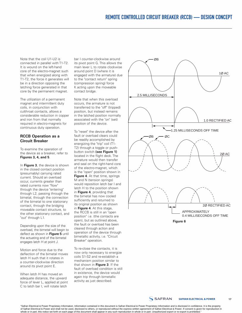
2.5 MILLISECONDS
1.0 RECTIFIED AC
2Ø RECTIFIED AC
APPROXIMATELY0.4 MILLISECONDS OFF TIME
1Ø AC
2Ø AC
ØB
ØB
ØC
1.25 MILLISECONDS OFF TIME
Figure 6
“Safran Electrical & Power Proprietary Information. Information contained in this document is Safran Electrical & Power Proprietary Information and is disclosed in confidence. It is the property of Safran Electrical & Power and shall not be used, disclosed to others, or reproduced without the express written agreement of Safran Electrical & Power. If consent is given for reproduction in whole or in part, this notice set forth on each page of this document shall appear in any such reproduction in whole or in part. Unauthorized export or re-export is prohibited.”
LABINAL POWER SYSTEMS TF300-9E 1918 SAFRAN ELECTRICAL & POWER
Three Pole RCCB
The design principles employed in the 3-pole RCCB have followed many of the same paths utilized in the 1-pole RCCB. Differences other than the obvious, such as size, weight, shape, etc., are explained below.
Motor Operation
The principles of motor operation and construction of the three pole devices are similar to those employed in the single pole RCCB. In the 3-pole device, the AC operating power is drawn from two of the three
phases. The "off" time between current pulses during coil energization is approximately 0.4 milliseconds. In comparison, the "off" time for single-phase power is approximately 1.25 milliseconds. See Figure 6.
The timing circuit establishes a coil "on" time longer than the actual transfer time of the armature. The operation of the 3-pole RCCB is identical to the1-pole.
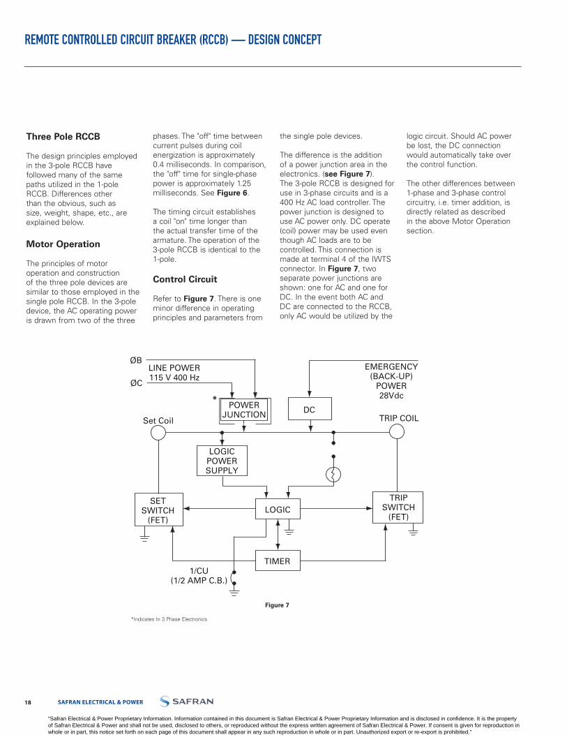
Control Circuit
Refer to Figure 7. There is one minor difference in operating principles and parameters from
the single pole devices.
The difference is the addition of a power junction area in the electronics. (see Figure 7).The 3-pole RCCB is designed for use in 3-phase circuits and is a 400 Hz AC load controller. The power junction is designed to use AC power only. DC operate (coil) power may be used even though AC loads are to be controlled. This connection is made at terminal 4 of the IWTS connector. In Figure 7, two separate power junctions are shown: one for AC and one for DC. In the event both AC andDC are connected to the RCCB,only AC would be utilized by the
logic circuit. Should AC power be lost, the DC connection would automatically take over the control function.
The other differences between 1-phase and 3-phase controlcircuitry, i.e. timer addition, isdirectly related as describedin the above Motor Operationsection.
LINE POWER115 V 400 Hz
1/CU(1/2 AMP C.B.)
SETSWITCH
(FET)
EMERGENCY(BACK-UP)
POWER28Vdc
TRIPSWITCH
(FET)
LOGICPOWERSUPPLY
POWERJUNCTION TRIP COIL
LOGIC
TIMER
DC
ØB
ØC
Set Coil
Figure 7
*Indicates In 3 Phase Electronics
*
REMOTE CONTROLLED CIRCUIT BREAKER (RCCB) — DESIGN CONCEPT
“Safran Electrical & Power Proprietary Information. Information contained in this document is Safran Electrical & Power Proprietary Information and is disclosed in confidence. It is the property of Safran Electrical & Power and shall not be used, disclosed to others, or reproduced without the express written agreement of Safran Electrical & Power. If consent is given for reproduction in whole or in part, this notice set forth on each page of this document shall appear in any such reproduction in whole or in part. Unauthorized export or re-export is prohibited.”
SAFRAN ELECTRICAL & POWER 1918 LABINAL POWER SYSTEMS TF300-9E
REMOTE POWER CONTROLLERS — WITH ELECTRONIC CURRENT SENSING
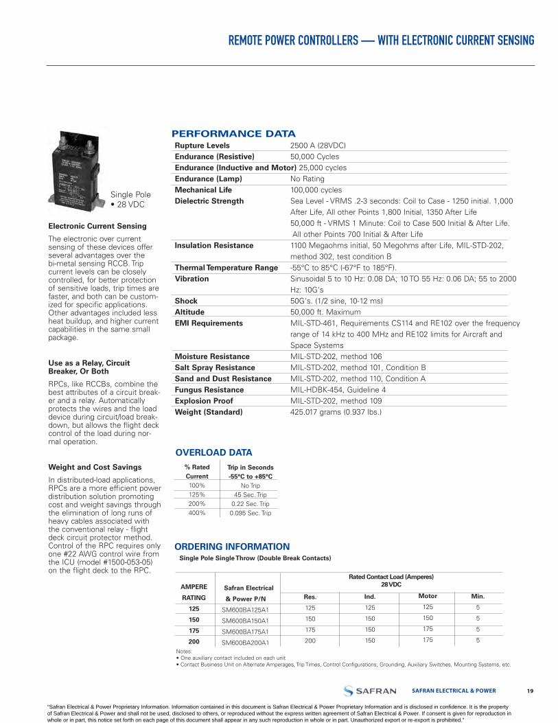
OVERLOAD DATA
% Rated Current100%125%200%400%
Trip in Seconds -55°C to +85°C
No Trip45 Sec. Trip
0.22 Sec. Trip0.095 Sec. Trip
Electronic Current Sensing
The electronic over current sensing of these devices offer several advantages over the bi-metal sensing RCCB. Trip current levels can be closely controlled, for better protection of sensitive loads, trip times are faster, and both can be custom-ized for specific applications. Other advantages included less heat buildup, and higher current capabilities in the same small package.
Use as a Relay, Circuit Breaker, Or Both
RPCs, like RCCBs, combine the best attributes of a circuit break-er and a relay. Automatically protects the wires and the load device during circuit/load break-down, but allows the flight deck control of the load during nor-mal operation.
Weight and Cost Savings
In distributed-load applications, RPCs are a more efficient power distribution solution promoting cost and weight savings through the elimination of long runs of heavy cables associated with the conventional relay - flight deck circuit protector method. Control of the RPC requires only one #22 AWG control wire from the ICU (model #1500-053-05) on the flight deck to the RPC.
Single Pole• 28 VDC
ORDERING INFORMATION
AMPERE
RATING
125
150
175
200
Safran Electrical
& Power P/N
SM600BA125A1
SM600BA150A1
SM600BA175A1
SM600BA200A1
Single Pole Single Throw (Double Break Contacts)
Rated Contact Load (Amperes)28 VDC
Res.
125
150
175
200
Ind.
125
150
150
150
Motor
125
150
175
175
Min.
5
5
5
5
Notes:• One auxiliary contact included on each unit• Contact Business Unit on Alternate Amperages, Trip Times, Control Configurations, Grounding, Auxiliary Switches, Mounting Systems, etc.
PERFORMANCE DATARupture Levels 2500 A (28VDC)Endurance (Resistive) 50,000 CyclesEndurance (Inductive and Motor) 25,000 cyclesEndurance (Lamp) No RatingMechanical Life 100,000 cyclesDielectric Strength Sea Level - VRMS .2-3 seconds: Coil to Case - 1250 initial. 1,000
After Life, All other Points 1,800 Initial, 1350 After Life50,000 ft - VRMS 1 Minute: Coil to Case 500 Initial & After Life. All other Points 700 Initial & After Life
Insulation Resistance 1100 Megaohms initial, 50 Megohms after Life, MIL-STD-202,method 302, test condition B
Thermal Temperature Range -55°C to 85°C (-67°F to 185°F).Vibration Sinusoidal 5 to 10 Hz: 0.08 DA; 10 TO 55 Hz: 0.06 DA; 55 to 2000
Hz: 10G'sShock 50G's. (1/2 sine, 10-12 ms)Altitude 50,000 ft. MaximumEMI Requirements MIL-STD-461, Requirements CS114 and RE102 over the frequency
range of 14 kHz to 400 MHz and RE102 limits for Aircraft andSpace Systems
Moisture Resistance MIL-STD-202, method 106Salt Spray Resistance MIL-STD-202, method 101, Condition BSand and Dust Resistance MIL-STD-202, method 110, Condition AFungus Resistance MIL-HDBK-454, Guideline 4Explosion Proof MIL-STD-202, method 109Weight (Standard) 425.017 grams (0.937 lbs.)
“Safran Electrical & Power Proprietary Information. Information contained in this document is Safran Electrical & Power Proprietary Information and is disclosed in confidence. It is the property of Safran Electrical & Power and shall not be used, disclosed to others, or reproduced without the express written agreement of Safran Electrical & Power. If consent is given for reproduction in whole or in part, this notice set forth on each page of this document shall appear in any such reproduction in whole or in part. Unauthorized export or re-export is prohibited.”

LABINAL POWER SYSTEMS TF300-9E 2120 SAFRAN ELECTRICAL & POWER
REMOTE POWER CONTROLLER (RPC)
Engineering Data
Typical Wiring Diagram Approximate Dimensions
A2 A1
3 A2 A2 A2
LOAD LINE
28 VDCBack Up Power
To Indicator /Control Unit Circuit Breaker Type MS22073 - 1/2 Or MS26574 - 1/2
S2
S3S1
A1A2
Auxiliary Contacts
Ove
r C
urre
nt D
etec
tor
5A 5B
3
4
5A 3
5B S3 S2 S1
4
Module: Integrated wire termination. Terminals will accept PIN contact per M39029/1 - 101. Use insertion/extraction tool M81969/14 - 02.
COIL OPERATE CURRENT/SET AND TRIP TIME
Nominal System Voltage
28 VDC (18 volts
Min)
I/C Set Current @
Nom. Voltage (milliamp)
2
Set Coil Current @Nom Voltage Pulse
3.7 Amp
Nominal Voltage @
Room Temp
20 Millisec
MAX. Set Time
Most Adverse Condition-Min. Voltage 71°C
Ambient
35 Millisec
*I/CU. Trip Current Nominal
71°C and Nominal Voltage
1.76 Amp
-54°C andNominal Voltage
1.25 Amp
Room Temp and Nominal
Voltage
1.89 Amp
Max. Standby Current
(milliamp)
30
* MAX I/CU. LINE IMPEDANCE 7.5 Ohms CURRENT DECREASES W/TIME SO THAT I2t >= 2
Typical Placement of Rating on Top Plane
LOA
D A
2
LIN
E A
1
125
.172/4.37 DIA.2 MTG. HOLES
.688/17.48
2.94074.68
3.25082.55
Position IndicatorRed: ClosedGreen: Open
1.53038.86
2.25057.15 .350
8.89 .071.778
.05/1.27
.1804.57
3.4286.87
Name Plate
R.061.52
4.26108.20
.0561.42
.4210.67
1.20030.48
Integrated Wire Module
.256/6.50
.1503.81
Barrier Black Nylon Per MIL-M-
20693A Type I. GeneralPurpose
Terminal Pad .6 DIA.
Approximate Dimensions - 1 Pole
“Safran Electrical & Power Proprietary Information. Information contained in this document is Safran Electrical & Power Proprietary Information and is disclosed in confidence. It is the property of Safran Electrical & Power and shall not be used, disclosed to others, or reproduced without the express written agreement of Safran Electrical & Power. If consent is given for reproduction in whole or in part, this notice set forth on each page of this document shall appear in any such reproduction in whole or in part. Unauthorized export or re-export is prohibited.”
SAFRAN ELECTRICAL & POWER 2120 LABINAL POWER SYSTEMS TF300-9E
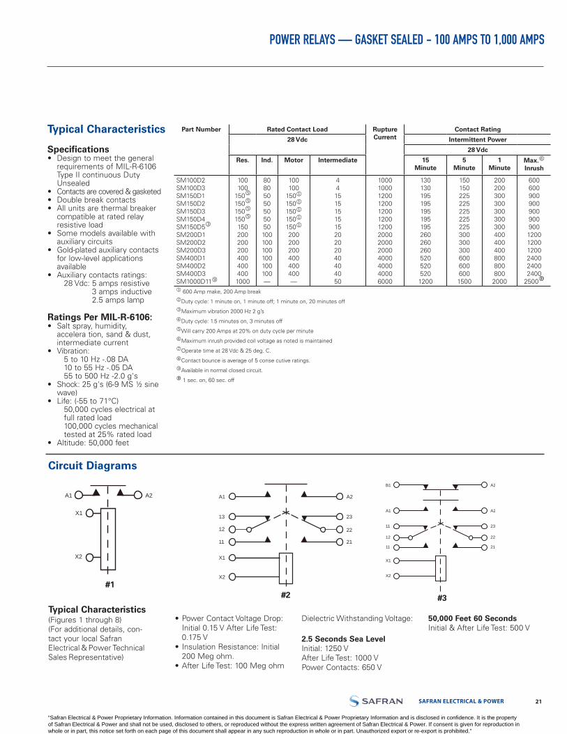
POWER RELAYS — GASKET SEALED - 100 AMPS TO 1,000 AMPS
Typical Characteristics
Specifications• Design to meet the general
requirements of MIL-R-6106Type II continuous DutyUnsealed
• Contacts are covered & gasketed• Double break contacts• All units are thermal breaker
compatible at rated relayresistive load
• Some models available withauxiliary circuits
• Gold-plated auxiliary contactsfor low-level applicationsavailable
• Auxiliary contacts ratings:28 Vdc: 5 amps resistive
3 amps inductive2.5 amps lamp
Ratings Per MIL-R-6106:• Salt spray, humidity,
accelera tion, sand & dust,intermediate current
• Vibration:5 to 10 Hz -.08 DA10 to 55 Hz -.05 DA55 to 500 Hz -2.0 g's
• Shock: 25 g's (6-9 MS ½ sinewave)
• Life: (-55 to 71°C)50,000 cycles electrical atfull rated load100,000 cycles mechanical tested at 25% rated load
• Altitude: 50,000 feet
Typical Characteristics (Figures 1 through 8)(For additional details, con-tact your local Safran Electrical & Power Technical Sales Representative)
• Power Contact Voltage Drop:Initial 0.15 V After Life Test: 0.175 V
• Insulation Resistance: Initial200 Meg ohm.
• After Life Test: 100 Meg ohm
Dielectric Withstanding Voltage:
2.5 Seconds Sea LevelInitial: 1250 VAfter Life Test: 1000 VPower Contacts: 650 V
50,000 Feet 60 SecondsInitial & After Life Test: 500 V
Circuit Diagrams
A1 A2
#1
X1
X2
#2
X1
X2
A1
13
12
11
A2
23
22
21
A2
#3
X1
X2
B1
A1
12
11
11
A2
23
22
21
A1 A2
#1
X1
X2
#2
X1
X2
A1
13
12
11
A2
23
22
21
A2
#3
X1
X2
B1
A1
12
11
11
A2
23
22
21
A1 A2
#1
X1
X2
#2
X1
X2
A1
13
12
11
A2
23
22
21
A2
#3
X1
X2
B1
A1
12
11
11
A2
23
22
21
#1#2 #3
Part Number Rated Contact Load Rupture Current
Contact Rating
28 Vdc Intermittent Power
28 Vdc
Res. Ind. Motor Intermediate 15Minute
5Minute
1Minute
Max.o
Inrush
SM100D2SM100D3SM150D1SM150D2SM150D3SM150D4SM150D5l
SM200D1SM200D2SM200D3SM400D1SM400D2SM400D3SM1000D11r
100100
150n
150n
150n
150n
1502002002004004004001000
80805050505050100100100100100100—
100100
150150150150150200200200400400400—
44151515151520202040404050
10001000120012001200120012002000200020004000400040006000
1301301951951951951952602602605205205201200
1501502252252252252253003003006006006001500
200200300300300300300400400400800800800
2000
600600900900900900900120012001200240024002400
2500s
600 Amp make, 200 Amp breakkDuty cycle: 1 minute on, 1 minute off; 1 minute on, 20 minutes offlMaximum vibration 2000 Hz 2 g’smDuty cycle: 1.5 minutes on, 3 minutes offnWill carry 200 Amps at 20% on duty cycle per minuteoMaximum inrush provided coil voltage as noted is maintainedpOperate time at 28 Vdc & 25 deg. C.qContact bounce is average of 5 conse cutive ratings.rAvailable in normal closed circuit.s 1 sec. on, 60 sec. off
“Safran Electrical & Power Proprietary Information. Information contained in this document is Safran Electrical & Power Proprietary Information and is disclosed in confidence. It is the property of Safran Electrical & Power and shall not be used, disclosed to others, or reproduced without the express written agreement of Safran Electrical & Power. If consent is given for reproduction in whole or in part, this notice set forth on each page of this document shall appear in any such reproduction in whole or in part. Unauthorized export or re-export is prohibited.”
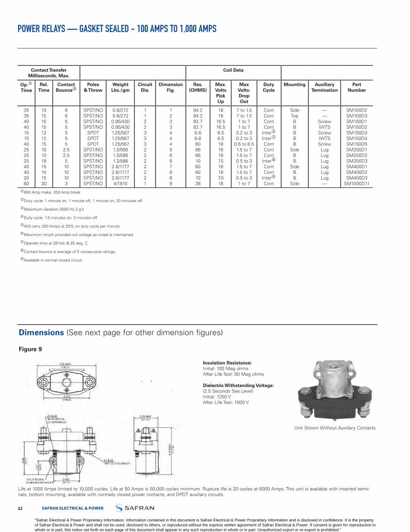
LABINAL POWER SYSTEMS TF300-9E 2322 SAFRAN ELECTRICAL & POWER
POWER RELAYS — GASKET SEALED - 100 AMPS TO 1,000 AMPS
Insulation Resistance:Initial: 100 Meg ohmsAfter Life Test: 50 Meg ohms
Dielectric Withstanding Voltage:(2.5 Seconds Sea Level)Initial: 1250 VAfter Life Test: 1000 V
Dimensions (See next page for other dimension figures)
Figure 9
Life at 1000 Amps limited to 10,000 cycles. Life at 50 Amps is 50,000 cycles minimum. Rupture life is 20 cycles at 6000 Amps. This unit is available with inverted termi-nals, bottom mounting, available with normally closed power contacts, and DPDT auxiliary circuits.
Unit Shown Without Auxiliary Contacts
Contact TransferMilliseconds, Max.
Coil Data
Op.o
TimeRel.
TimeContact
BounceqPoles
& ThrowWeightLbs./gm
CircuitDia.
DimensionFig.
Res.(OHMS)
Max.VoltsPick Up
MaxVolts-Drop Out
DutyCycle
Mounting AuxiliaryTermination
PartNumber
3535404015154025252540402060
1515151512121510101815151530
6655555
2.52.551010103
SPST/NOSPST/NOSPST/NOSPST/NO
SPDTSPDTSPDT
SPST/NOSPST/NOSPST/NOSPST/NOSPST/NOSPST/NOSPST/NO
0.6/2720.6/2720.95/4300.95/4301.25/5671.25/5671.25/5671.3/5881.3/5881.3/5882.6/11772.6/11772.6/11774/1810
11223332222221
12334445667889
94.294.282.782.76.66.66066661060601038
1818
16.516.56.56.51818187.518187.018
7 to 1.57 to 1.51 to 71 to 7
0.2 to 30.2 to 3
0.6 to 8.51.5 to 71.5 to 70.5 to 31.5 to 71.5 to 70.5 to 31 to 7
ContContContCont
InterkInterkContContCont
IntermContCont
IntermCont
SideTopBBBBB
SideBB
SideBB
Side
——
ScrewIWTSScrewIWTSScrew
LugLugLugLugLugLug—
SM100D2SM100D3SM150D1SM150D2SM150D3SM150D4SM150D5SM200D1SM200D2SM200D3SM400D1SM400D2SM400D3
SM1000D11
600 Amp make, 200 Amp break
kDuty cycle: 1 minute on, 1 minute off; 1 minute on, 20 minutes off
lMaximum vibration 2000 Hz 2 g’s
mDuty cycle: 1.5 minutes on, 3 minutes off
nWill carry 200 Amps at 20% on duty cycle per minute
oMaximum inrush provided coil voltage as noted is maintained
pOperate time at 28 Vdc & 25 deg. C.
qContact bounce is average of 5 consecutive ratings.
rAvailable in normal closed circuit.
“Safran Electrical & Power Proprietary Information. Information contained in this document is Safran Electrical & Power Proprietary Information and is disclosed in confidence. It is the property of Safran Electrical & Power and shall not be used, disclosed to others, or reproduced without the express written agreement of Safran Electrical & Power. If consent is given for reproduction in whole or in part, this notice set forth on each page of this document shall appear in any such reproduction in whole or in part. Unauthorized export or re-export is prohibited.”

SAFRAN ELECTRICAL & POWER 2322 LABINAL POWER SYSTEMS TF300-9E
POWER RELAYS — GASKET SEALED - 100 AMPS TO 1,000 AMPS
Dimension Figures
Figure 1 Figure 2
Figure 3 Figure 4
X1 X2
1.875(47.62)
2.385(60.55)
.937 (23.8)
.219 (5.56) DIA.(2) MOUNTING
HOLES
.422 (10,7)
2.68(68.0)
#6-32 UNC-2A2 COIL TERM
1.72
(43.
69).9
86(2
5.0)
.625(15.87)
2.22(56.38)
2.75
(69.
85)
.250(6.35)-28 UNF-3A2 Power Term
SM100D2 SM100D3
SM150D4
Unit Shown Without Auxiliary Contacts
2.64(67)
.219(5.56) DIA. MOUNTING HOLES
1.312(33.3)
2.68
(68)
2.22(56.3)
2.188(55.5)
.250 (6.35)-28 UNF-3A2 POWER TERM
.625(15.8)
2.68(68)
1.72
(43.
6)
X2 X1
SM150D1
SM150D2
SM150D3SM150D5
SM150D4
SM150D2
Unit Shown Without Auxiliary Contacts
X2X1
A2
A1
WILL ACCEPT TERMINAL-PINCONNECTION (DEUTSCH PARTNO. 1841-1-5620)
.203 (5.15) ± .005 DIA.4 MOUNTING HOLES
2.75
(69.
8)
187
MTG
(47.
5)
2.19
(55.
6)
1.87 MTG
(47.5)
4.50
(114
.3)
2.25
(57.1)
2.25
(57.1)
#6-32 UNC-2A6 AUX. TERMINALS
#6-32 UNC-2A2 COIL TERMINALS
.75
(19)
.250 (6.35)-28 UNF-2A2 POWER TERMINALS
X2X1
B2
B3
A2
A1
.250 (6.35)-28 UNF-2A4 POWER TERMINALS
WILL EXCEPT TERMINAL-PINCONNECTION (DEUTSCH PARTNO 1841-1-5620)
.203 (5.15) ± .005 DIA.4 MOUNTING HOLES
2.75
(69.
8)
187
MTG
(47.
5)
2.19
(55.
6)
1.87 MTG(47.5)
4.50
(114
.3)
2.25(57.1)
2.25(57.1)
#6-32 UNC-2A6 AUX. TERMINALS
#6-32 UNC-2A2 COIL TERMINALS
.75(19)
.75(19)
“Safran Electrical & Power Proprietary Information. Information contained in this document is Safran Electrical & Power Proprietary Information and is disclosed in confidence. It is the property of Safran Electrical & Power and shall not be used, disclosed to others, or reproduced without the express written agreement of Safran Electrical & Power. If consent is given for reproduction in whole or in part, this notice set forth on each page of this document shall appear in any such reproduction in whole or in part. Unauthorized export or re-export is prohibited.”
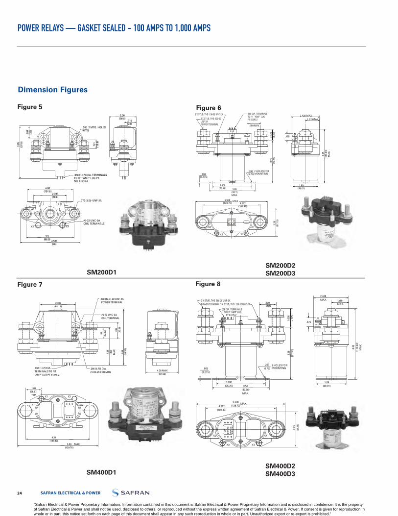
LABINAL POWER SYSTEMS TF300-9E 2524 SAFRAN ELECTRICAL & POWER
POWER RELAYS — GASKET SEALED - 100 AMPS TO 1,000 AMPS
Dimension Figures
Figure 5 Figure 6
Figure 7 Figure 8
SM200D1
SM400D1
SM200D2SM200D3
SM400D2SM400D3
2.00(50.8)
.916(23)
.984
(25)
3.85
(97.
8)
.266 2 MTG. HOLES(6.75)
.781
(1
9.8)
X2X1
A2A1
4.00(101.6)
2.395(60.8)
3.5(68.9) 4.500
(76)
.375 (9.5)- UNF-2A
#6-32 UNC-2ACOIL TERMINALS
.058 (1.47) DIA. TERMINALSTO FIT "AMP" LUG PT.NO. 61276-2
.058 (1.47) DIA. TERMINALS TO FIT"AMP" LUG PT 61276-2
4.38 MAX(61.93)
4.31(109.47)
1.05(26.67)
TYP.
5.50(139.70)
1.06
(26.
9)3.
92(9
9.57
)
1.28
(32)
MA
X
.81
(20.
57)
2.406(61.11)
.500 (12.7)-20 UNF-2APOWER TERMINAL
#6-32 UNC-2ACOIL TERMINAL
.266 (6.76) DIA.2 HOLES FOR MTG
MAX.
A2A1
X1 X2
.058 DIA. TERMINALS TO FIT "AMP" LUG
PT 61276-2
1.219 MAX.
.266(6.76)
2 HOLES FOR MOUNTING
3.25
(82.
55)
3.000(76.20) 3.53
(89.66)MAX.
1.89(48.01)
1.00
0±.
125
.475
.500MIN.
5.500(139.70)
MAX.
.062(1.575)
4.45
(113
.03)
MA
X.
2.438 MAX.
4.312(109.47)
2.25
(57.
15)
A2
X2 X1
A1
2 X STUD, THD .138-32 UNC-2A2 X STUD, THD .500-20 UNF-2APOWER TERMINAL
.058 DIA. TERMINALSTO FIT “AMP” LUGPT 61276-2 1.219 MAX.
.266(6.76)
2 HOLES FOR MOUNTING
3.25
(82.
55)
3.000(76.20) 3.65
(92.7)MAX.
1.89(48.01)
±.12
5(1
.13)
.475
.500 MIN.
5.500(139.70)
MAX.
.062(1.575)
4.45
(113
.03)
MA
X.
2.438 MAX.
4.312(109.47)
2.25
(57.
15)
A2
X2 X1
A1
2 X STUD, THD .138-32 UNC-2A
2 X STUD, THD .500-20 UNF-2APOWER TERMINAL
“Safran Electrical & Power Proprietary Information. Information contained in this document is Safran Electrical & Power Proprietary Information and is disclosed in confidence. It is the property of Safran Electrical & Power and shall not be used, disclosed to others, or reproduced without the express written agreement of Safran Electrical & Power. If consent is given for reproduction in whole or in part, this notice set forth on each page of this document shall appear in any such reproduction in whole or in part. Unauthorized export or re-export is prohibited.”
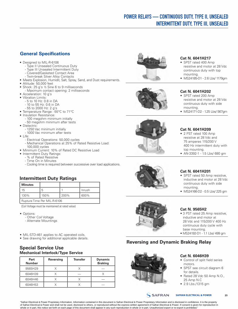
SAFRAN ELECTRICAL & POWER 2524 LABINAL POWER SYSTEMS TF300-9E
POWER RELAYS — CONTINUOUS DUTY, TYPE II, UNSEALEDINTERMITTENT DUTY, TYPE III, UNSEALED
General Specifications
• Designed to MIL-R-6106- Type II Unsealed Continuous Duty- Type III Unsealed Intermittent Duty- Covered/Gasketed Contact Area- Twin-break Silver Alloy Contacts
• Meets Explosion, Humidit, Salt, Spray, Sand, and Dust requirements.• Altitude: 50,000 feet• Shock: 25 g's ½ Sine 6 to 9 milliseconds
- Maximum contact opening: 2 milliseconds• Acceleration: 10 g's• Vibration Limits:
- 5 to 10 Hz: 0.8 in DA- 10 to 55 Hz: 0.6 in DA- 55 to 2000 Hz: 2 g's
• Temperature Range: -55°C to 71°C• Insulation Resistance:
- 100 megohm minimum initially- 50 megohm minimum after tests
• Dielectric:- 1250 Vac minimum initially- 1000 Vac minimum after tests
• Life:- Electrical Operations: 50,000 cycles- Mechanical Operations at 25% of Rated Resistive Load:
100,000 cycles• Minimum Current: 10% of Rated DC Resistive Load• Intermittent Duty Ratings:
- % of Rated Resistive- Time On in Minutes- Cooling time is required between successive over load applications.
Intermittent Duty Ratings
• Options:- Other Coil Voltage- Alternate Mountings
• MIL-STD-461 applies to AC operated coils.• See drawing for additional applicable details.
Cat N. 6041H217• SPST rated 400 Amp
resistive and motor at 28 Vdccontinuous duty with topmounting.
• MS24185-D1 - 2.6 Lbs/ 1179gm
Cat N. 6041H202• SPST rated 200 Amp
resistive and motor at 28 Vdccontinuous duty with sidemounting.
• MS24171-D2 - 1.25 Lbs/ 567gm
Cat N. 6041H209• 2 PST rated 100 Amp
resistive at 28 Vdc and75 amperes 115/200 V400 Hz intermittent duty withtop mounting.
• AN-3392-1 - 1.5 Lbs/ 680 gm
Cat N. 6041H201• SPST rated 50 Amp resistive,
inductive and motor at 28 Vdccontinuous duty with sidemounting.
• MS24166-D2 - 0.5 Lbs/ 225 gm
Cat N. 9565H2• 3 PST rated 25 Amp resistive,
inductive and motor at28 Vdc and 115/200 V 400 Hzcontinuous duty cycle withbase mounting.
• MS24192-D1 - 1.1 Lbs/ 499 gm
Cat N. 6046H39• Control of split field series
motors.• SPST see circuit diagram 6
for details.• Rated 28 Vdc 50 Amp N.O.,
25 Amp N.C• 2.9 Lbs./1315 gm
Minutes
15 5 1 Inrush
130% 150% 200% 600%
Rupture Time Per MIL-R-6106
(Coil Voltage must be maintained at rated value)
Special Service UseMechanical Interlock/Type Service
PartNumber
Reversing Transfer Dynamic Braking
9565H29 X X —
6046H39 X — X
6046H46 X X —
6046H53 X X —
Reversing and Dynamic Braking Relay
“Safran Electrical & Power Proprietary Information. Information contained in this document is Safran Electrical & Power Proprietary Information and is disclosed in confidence. It is the property of Safran Electrical & Power and shall not be used, disclosed to others, or reproduced without the express written agreement of Safran Electrical & Power. If consent is given for reproduction in whole or in part, this notice set forth on each page of this document shall appear in any such reproduction in whole or in part. Unauthorized export or re-export is prohibited.”

LABINAL POWER SYSTEMS TF300-9E 2726 SAFRAN ELECTRICAL & POWER
POWER RELAYS — CONTINUOUS DUTY, TYPE II, UNSEALEDINTERMITTENT DUTY, TYPE III, UNSEALED
Safran Electrical & Power
PartNumber
Government Part
Number
Continuous Power Contacts, Ratings Contacts OperateMilliseconds, Maximum
Coil Data
28VDC 115/200 VAC 400 Hz. Contact Bounce
Poles & Throwm
Weight Lbs./GMS
Circuit Dia./Dim.
Figure
Resistance (OHMS)±
10% Pickup/Sealed
Volts Pickupn
Volts Drop-outo
Duty Cycle
Mounting Coil Voltage Nominal
RES. IND. MOTOR RES. IND. MOTOR OP. TIME
REL TIME
9565H29565H299565H95
6041H53k
6041H220k
6041H230
6046H39k6041H2016041H1496041H2009565H946041H2196041H806041H1446041H11
6041H2096046H539565H136041H2026041H1056041H1236041H2036041H2126041H2156041H2166046H466041H2056041H217
MS24192-D1MS24152-D1
——
MS24187-D1
MS24187-D2
—MS24166-D2
—MS24166-D1MS24193-D1MS24178-D1
———
AN3362-1MS25031-D1B
—MS24171-D2
——
MS24172-D2—
MS24171-D1MS24172-D1MS25032-D1MS24185-D2MS24185-D1
252525
50/25
50/25
50/25
50/255050505055100100100100100100200200200200200200200200400400
252525
50/25
50/25
50/25
50/255050505040808080808075100100100100100100100100100100
252525
50/25
50/25
50/25
50/255050505040808080808075
200200200200200200200150400400
252525
25/25
25/25
25/25
————5055———7575100———————
150————
252525—
—
—
————50———————————————————
252525—
—
—
————5035———656575———————
100————
20202020
20
20
—20202020—
35
2225—4025402525404040
15151515
15
15
—10151015—
10
1510—1518151010151515
666
5 N.O./10 N.C.
5 N.O./10 N.C.
5 N.O./10 N.C.—5554—
3.5
450—555555555
3PST3PDT3PSTSPDT
SPDT
SPDT
SPDTSPSTSPSTSPST3PSTDPSTSPSTSPSTSPSTDPSTDPDT3PSTSPSTSPSTSPSTSPSTSPSTSPSTSPSTDPDTSPSTSPST
1.1/4982/909.09
1.06/482.95.54/245.45
.54/245.45
.54/245.45
2.9/1318.18.50/225
.56/254.55.50/2251.51/685
.75/340.911.4/636.361.4/636.361.4/636.36
1.5/6853.5/1590.912.5/1136.361.25/568.181.25/868.181.3/590.911.23/560
1.3/590.911.33/604.551.33/604.555.5/2500.002.6/1181.822.6/1181.82
10 / 1116 / 1110 / 114 / 2
4 / 2
4 /2
6 / 71 / 41 / 41 / 4
10 / 112 / 21 / 31 / 31 / 12 / 29 / 7
12 / 111 / 51 / 51 / 51 / 51 / 51 / 11 / 1 8 / 71 / 51 / 1
/ 6022 / 92/ 116016.9
94.2
94.2
2694.216.994.2
13.5 / 71.566
66.366.366.34343
9 / 5366
10 (+15/-10)66
10 (+15/-10)6666
10(+15/-10)416060
1818708.2
18
18
18188.2181818181818201818189187.518187.5181818
1.5 to 71.5 to 78 to 38
0.8 to 4.8
1.5 to 9
1.5 to 9
71.5 to 7
0.8 to 4.81.5 to 71.5 to 71.5 to 71.5 to 71.5 to 71.5 to 71.5 to 71.5 to 71.5 to 71.5 to 7
3.51.5 to 7
0.5 to 3.01.5 to 71.5 to 7
0.5 to 3.01.5 to 71.5 to 71.5 to 7
CONTCONTCONTCONT
CONT
CONT
CONTCONTCONTCONTNoteCONTCONTCONTNoteCONTCONTCONTCONTCONT
INTERlCONTCONT
INTERlCONTCONTCONT
BASEBASEBASETOP
TOP
TOP
TOPSIDESIDETOP
BASETOPSIDESIDETOPTOPTOP
BASESIDESIDESIDESIDESIDETOPTOPTOPSIDETOP
28 dc28 dc120 dc12 dc
28 dc
29 dc
28 dc28 dc12 dc28 dc28 dc28 dc28 dc28 dc28 dc28 dc28 dc28 dc28 dc12 dc28 dc28 dc28 dc28 dc28 dc28 dc28 dc28 dc
MS Part Number SummaryAN3362-1* 6041H209
MS24152-D1* 9565H29* MS24185-D2 6041H205
MS24166-D1 6041H200 MS24187-D1 6041H220
MS24166-D2 6041H201 MS24187-D2 6041H230
MS24171-D1 6041H215 MS24192-D1 9565H2
MS24171-D2 6041H202 MS24193-D1 9565H94
MS24172-D1 6041H216 MS25031-D1B 6046H53
MS24172-D2 6041H203 MS24185-D1 6041H217
MS24178-D1 6041H219 MS25032-1 6046H46
*Inactive for new design
Conversion Part NumberAN Part Number Use MS Part Number Safran Electrical &
Power Part Number
3343-1 — 9565H13
3350-1 MS24166-D2 6041H201
3362-1 — 6041H209
3370-1 MS24171-D2 6041H202
3371-1 MS24172-D2 6041H203
3380-1 MS24185-D2 6041H205
— MS25030-D1B 6041H51
Coil will exceed 95° C temperature rise when left on continuously in 25° ambient, but will not be damaged. At maximum ambient temperture of 71°C, the duty cycle should be limited to 15 minutes “on” time per half hour to obtain maximum coil life.
k Continuous and intermittent duty ratings shown are for N.O. pole rated at 1/2 the listed continuous DC duty ratings. N.C. pole on 6041H53 and H220 limited
to 15 g’s shock.l Time on 1 1/2 minutes at 29 Vdc. Minimum time off is 3 minutes.
m All continuous duty resistive and motor load ratings and all intermittent duty ratings for all 3 pole relays listed under 28 Vdc apply for 120 Vdc systems with all 3 poles of the relay connected in the series.
n Pick-up voltage below values shown may cause relay to rapidly cycle on and off (chatter).o Relay must drop-out at voltage value or less and may drop-out at any voltage
below the higher voltage noted.
“Safran Electrical & Power Proprietary Information. Information contained in this document is Safran Electrical & Power Proprietary Information and is disclosed in confidence. It is the property of Safran Electrical & Power and shall not be used, disclosed to others, or reproduced without the express written agreement of Safran Electrical & Power. If consent is given for reproduction in whole or in part, this notice set forth on each page of this document shall appear in any such reproduction in whole or in part. Unauthorized export or re-export is prohibited.”
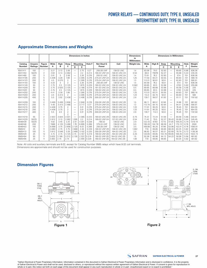
SAFRAN ELECTRICAL & POWER 2726 LABINAL POWER SYSTEMS TF300-9E
Dimensions in Inches Dimensions in
Millimeters
Dimensions in Millimeters
Catalog Number
Ampere Ratings
Figure Number
Wide A
High B
Deep C
Mounting Hole F Net Stud G Power
Coil Weight Lbs. Wide A
High B Deep Mounting Hole F
Weight GramsD E C D E
6041H116041H536041H806041H1056041H1236041H1446041H1496041H2006041H2016041H2026041H2036041H205
6041H2096041H2126041H2156041H2166041H217
6041H2196041H2206046H396046H466046H539565H29565H139565H299565H949565H95
10050/25100200200100505050
200200400
100200200200400
5550/2550/2520010025100255025
1235634245555251111227771111121111
3.272.632.914.4064.53.332.752.752.754.414.55.5
3.4694.484.4064.4065.5
2.9222.8124.827.6886.6883.0633.8124.75
3.6253.063
3.133.14
33.283.575
32.5
2.6252.53.283.3133.92
3.4063.3133.753.754.5
2.8443.133.454.1253.752.753.5462.75
3.1882.75
2.082.0622.081.99
22
2.1252.1252.1251.99
22.438
2.6562.466
2222
2.0312.0622.253.4682.6562.753.284.1253.3122.75
————————————————————
1.3952.011.76
2.1252.6882.4682.752.135
2.752.22.262.3952.3952.261.8752.1881.8752.3952.3952.406
2.9483.7173.013.013.01
2.3852.2
4.3016.8956.022.493.1024.1872.3222.494
0.270.2140.2760.2760.2760.2760.2290.2190.2290.2760.2760.276
0.2760.270.2760.2760.276
0.2230.2140.2280.2660.2660.2290.2250.218
0.2190.229
.250-28 UNF.190-32 UNF-2A
.250-32 UNC.375-24 UNF-2A.375-24 UNF-2A
.250-28 UNF.190-32 UNC-2A.191-32 UNC-2A.190-32 UNC-2A.375-24 UNF-2A.375-24 UNF-2A.500-20 UNF-2A
.250-28 UNF-2B
.375-24 UNF-2A
.375-24 UNF-2A
.375-24 UNF-2A
.500-20 UNF-2A
.190-32 UNC-2B
.190-32 UNF-2A.190-32
.375-24 UNF
.250-28 UNF.190-32 UNF-2B.250-28 UNF-2B.190-32 UNF-2B.190-32 UNF-2B.190-32 UNF-2B
.138-32 UNC.138-32 UNC-2A.138-32 UNC-2A.138-32 UNC-2A.138-32 UNC-2A
.138-32 UNC.138-32 UNC-2A.138-32 UNC-2A.138-32 UNC-2A.138-32 UNC-2A.138-32 UNC-2A.138-32 UNC-2A
.138-32 UNC-2B
.138-32 UNC-2A
.138-32 UNC-2A
.138-32 UNC-2A
.138-32 UNC-2A
.138-32 UNC-2B
.137-32 UNC-2A.138-32 UNC.138-32 UNC.138-32 UNC
.138-32 UNC-2B
.164-32 UNC-2B
.164-32 UNC-2B.164-32 UNC-2B.164-32 UNC-2B
1.40.541.41.251.31.4
0.5620.50.51.251.232.6
1.51.31.331.332.6
0.750.542.95.53.5
1.0622.52.251.51.06
83.0666.873.91111.92112.0184.5869.8569.8569.85112.01114.3139.7
88.11113.79111.91111.91139.7
74.2271.42
122.43195.28169.88
77.896.82120.6592.0877.8
79.57907676.2
83.3190.8176.263.566.6863.583.3184.1599.57
86.5184.1595.2595.25114.3
72.2479.587.63
104.7895.2569.8590.0769.8580.9869.85
52.8352.3752.8350.5550.850.853.9853.9853.9850.5550.861.93
67.4662.6450.850.850.8
51.5952.3757.1588.0967.4669.8583.31104.7884.1269.85
————————————————————
35.4351.0544.753.9868.2862.6969.8554.23
69.8555.8857.4
60.8362.8357.4
47.6355.5847.6360.8360.8361.11
74.8894.4176.4576.4576.45
60.5855.88109.25175.13152.9163.2578.79106.3558.9863.35
6.865.447.017.017.017.015.825.565.827.017.017.01
7.016.867.017.017.01
5.665.445.796.766.765.825.725.545.565.82
636.36245.45636.36568.18590.91636.36255.68
225225
568.18560
1181.82
681.82590.91604.55604.551181.82
340.91245.451318.18
25001590.91482.951136.361022.73681.82481.82
POWER RELAYS — CONTINUOUS DUTY, TYPE II, UNSEALED INTERMITTENT DUTY, TYPE III, UNSEALED
Approximate Dimensions and Weights
Note: All coils and auxiliary terminals are 6-32, except for Catalog Number 9565 relays which have 8-32 coil terminals.Dimensions are approximate and should not be used for construction purposes.
Dimension Figures
Figure 1 Figure 2
B
E
C
A
DIA. GTERM.STUD
DIA. FMTG.
HOLES
A4
A4 A1C
G. DIA.TERM.STUDS
F DIAMTG. HOLES
A
A3
X2 X2
E
B
A4
A4 A1C
G. DIA.TERM.STUDS
F DIAMTG. HOLES
A
A3
X2 X2
E
B
“Safran Electrical & Power Proprietary Information. Information contained in this document is Safran Electrical & Power Proprietary Information and is disclosed in confidence. It is the property of Safran Electrical & Power and shall not be used, disclosed to others, or reproduced without the express written agreement of Safran Electrical & Power. If consent is given for reproduction in whole or in part, this notice set forth on each page of this document shall appear in any such reproduction in whole or in part. Unauthorized export or re-export is prohibited.”
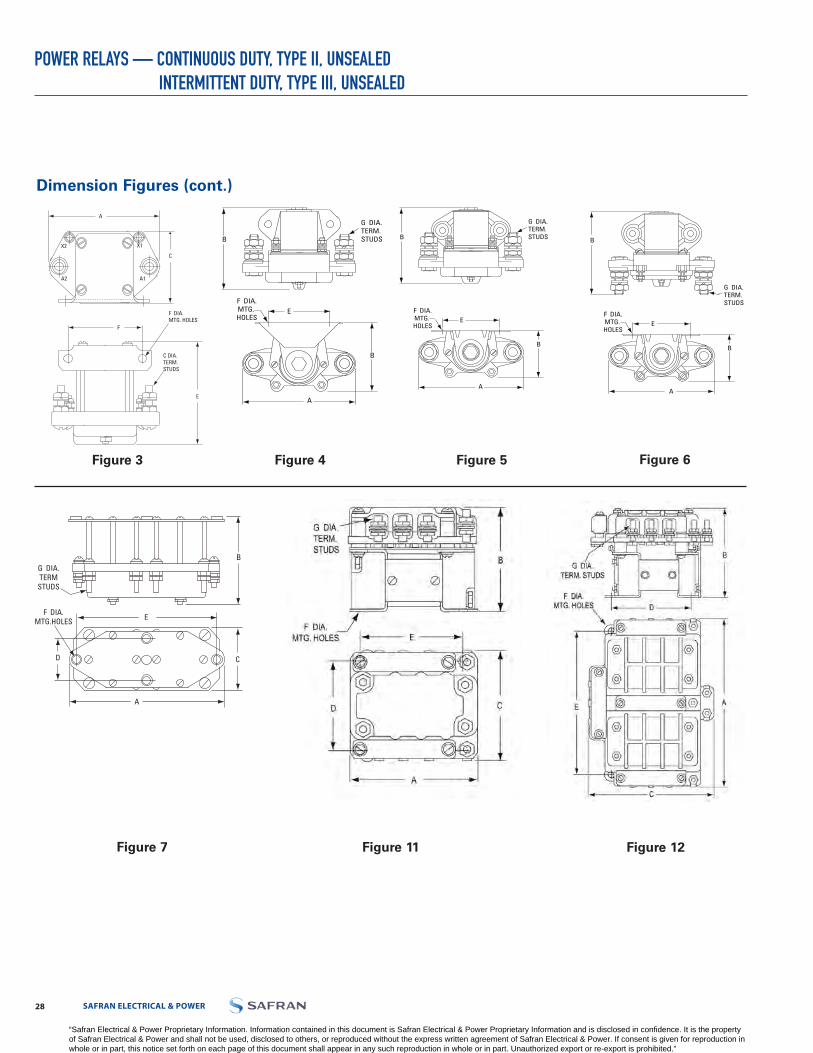
LABINAL POWER SYSTEMS TF300-9E 2928 SAFRAN ELECTRICAL & POWER
POWER RELAYS — CONTINUOUS DUTY, TYPE II, UNSEALEDINTERMITTENT DUTY, TYPE III, UNSEALED
Dimension Figures (cont.)
Figure 3 Figure 4 Figure 5 Figure 6
Figure 7 Figure 11 Figure 12
A
C
X2
A2 A1
X1
E
F DIA.MTG. HOLES
C DIA.TERM.STUDS
F
A
G DIA.TERM.STUDSB
B
EF DIA.MTG. HOLES
A
EF DIA.MTG. HOLES
B
G DIA.TERM.STUDSB
G DIA.TERM.STUDS
B
A
EF DIA.MTG. HOLES
B
C
B
EF DIA.
MTG.HOLES
G DIA.TERM
STUDS
D
A
“Safran Electrical & Power Proprietary Information. Information contained in this document is Safran Electrical & Power Proprietary Information and is disclosed in confidence. It is the property of Safran Electrical & Power and shall not be used, disclosed to others, or reproduced without the express written agreement of Safran Electrical & Power. If consent is given for reproduction in whole or in part, this notice set forth on each page of this document shall appear in any such reproduction in whole or in part. Unauthorized export or re-export is prohibited.”

SAFRAN ELECTRICAL & POWER 2928 LABINAL POWER SYSTEMS TF300-9E
POWER RELAYS — CONTINUOUS DUTY, TYPE II, UNSEALED INTERMITTENT DUTY, TYPE III, UNSEALED
Typical Wiring Diagrams
Diagram 1 Diagram 2 Diagram 3 Diagram 4
Diagram 8 Diagram 9 Diagram 10
Diagram 12 Diagram 16 Diagram 18
A1 A2
X1
X2
A1 A2
B1 B2
X1
X2
A1 A2
A3 A4
X1
X2
B1 B2
A1 A2
X1
X2
D1 D2
C1 C2
X3
X4
B1 B2
A1 A2
X1
X2
B4 A3
A4 A3
Y1
Y2
A1 A2
B1 B2
X1
X2
C1 C2
B1 B2
A1 A2
X1
X2
L1 T2
L1 T2
L1 T2
X1
X2
Y2
B1
A1
A2 B2 C2
C1
X2
X1
B3
A3
C3
Y1
X1
L2
L1
T1 T2 T3
L3
X2
X1
L12
L11
L13
X12
A1 A2
X1
X2
A1 A2
B1 B2
X1
X2
A1 A2
A3 A4
X1
X2
B1 B2
A1 A2
X1
X2
D1 D2
C1 C2
X3
X4
B1 B2
A1 A2
X1
X2
B4 A3
A4 A3
Y1
Y2
A1 A2
B1 B2
X1
X2
C1 C2
B1 B2
A1 A2
X1
X2
L1 T2
L1 T2
L1 T2
X1
X2
Y2
B1
A1
A2 B2 C2
C1
X2
X1
B3
A3
C3
Y1
X1
L2
L1
T1 T2 T3
L3
X2
X1
L12
L11
L13
X12
“Safran Electrical & Power Proprietary Information. Information contained in this document is Safran Electrical & Power Proprietary Information and is disclosed in confidence. It is the property of Safran Electrical & Power and shall not be used, disclosed to others, or reproduced without the express written agreement of Safran Electrical & Power. If consent is given for reproduction in whole or in part, this notice set forth on each page of this document shall appear in any such reproduction in whole or in part. Unauthorized export or re-export is prohibited.”

LABINAL POWER SYSTEMS TF300-9E 3130 SAFRAN ELECTRICAL & POWER
POWER RELAYS — CONTINUOUS DUTY, TYPE II, UNSEALEDINTERMITTENT DUTY, TYPE III, UNSEALED
P/N 6046H39
Typical Operation:All items shown within dotted lines are part of the relay. All other parts external to dotted lines, including switches connected to C1 & C2 customer supplied.
Internal Mechanical InterlocksPrevents the opposite contacts from transferring when either one of the coils is energized and the respective contacts are closed.
Reversing OperationClosing either external start/stop switch at C1 or C2 will cause the motor to turn in either direction.
Dynamic Braking OperationInternal switch provides for dynamic braking current flow through the motor shunt-fields series (SF) 1 and 2. Switch S is mechanically closed when either coil is energized and maintains that position until the alternate coil is energized. Switch S is shown in the last position commanded by external start/stop switch at C1.
L1+ L2-
C3
S.F.1
S.F.2ARM
S
1
D
2
C1
3
4
C2
Dia. No. 66046H39
(Items shown outside dotted lineare customer supplied)
“Safran Electrical & Power Proprietary Information. Information contained in this document is Safran Electrical & Power Proprietary Information and is disclosed in confidence. It is the property of Safran Electrical & Power and shall not be used, disclosed to others, or reproduced without the express written agreement of Safran Electrical & Power. If consent is given for reproduction in whole or in part, this notice set forth on each page of this document shall appear in any such reproduction in whole or in part. Unauthorized export or re-export is prohibited.”

SAFRAN ELECTRICAL & POWER 3130 LABINAL POWER SYSTEMS TF300-9E
POWER RELAYS — HERMETICALLY SEALED - 12 AMPS TO 50 AMPS
Typical Configurations
Cat. No. 6042H2853PST, 50 Amp w/Auxiliary
Cat. No. 6042H46SPST, 50 Amp w/Auxiliary
Cat. No. 6042H155SPST, 50 Amp
Characteristics:• Electrical Life: 50,000 cycles
(sea level to 80,000 feet)• Mechanical Life: 100,000 cycles• Acceleration: 15 g's• Shock: 25 g's
• Ambient Temperature Class:- B -70°C to 125°C- D -70°C to 71°C• Hermetically sealed/ MIL-PRF-6106• Twin Break Silver Alloy Main Contacts
• Vibration Levels (Typical):
5 - 10 CPS.08 DA
10 - 55 CPS.06 DA
55 - 200CPS10 g’s
250 - 500 CPS5 g’s
500 - 1500 CPS3 g’s
Catalog Number
ContinuousAmpere
Contact Rating
Poles and
Throw
Operating Coil Voltage
Number Aux
Contacts
Dimension DrawingFigure
Number
Wiring Diagram Figure
Number
Government Type Number
Temp Class/Note
6042H110-2 12 3PST
28 Vdc
1 2 8 MS24143-D3 Bk
6042H141-26042H142-2
25 3PST
— 2 6 MS24143-D1 B
1 2 8 MS24143-D2 Bp
6042H290-2
6042H291-2
115 Vac60 or
400 Hertz
Built InRectifiers
— 2 6 MS24143-A3 D
1 2 8 MS24143-A4 D
6042H155-2
50
SPST28 Vdc
— 1 9 MS24140-D1 B
6042H156-2 1 1 10 MS24140-D2 B
6042H145-2
6042H146-2
3PST
— 2 6 MS24376-D1 B
1 2 8 MS24376-D2 B
6042H147-2
6042H148-2
6042H285-2
6042H288-2
115 Vac60 or 400
Hertz
Built InRectifiers
— 2 6 MS24376-A1 Bs
1 2 8 MS24376-A2 Bs
1 2 8 MS24376-A4 Bs
— 2 6 MS24376-A3 Bs
“Safran Electrical & Power Proprietary Information. Information contained in this document is Safran Electrical & Power Proprietary Information and is disclosed in confidence. It is the property of Safran Electrical & Power and shall not be used, disclosed to others, or reproduced without the express written agreement of Safran Electrical & Power. If consent is given for reproduction in whole or in part, this notice set forth on each page of this document shall appear in any such reproduction in whole or in part. Unauthorized export or re-export is prohibited.”

LABINAL POWER SYSTEMS TF300-9E 3332 SAFRAN ELECTRICAL & POWER
POWER RELAYS — HERMETICALLY SEALED - 12 AMPS TO 50 AMPS
Ratings
Auxiliary Switch: SPDT rated 28 Vdc and 115 V 400 Hz, 5 Amp Res. & Ind. & 0.75 Amp Lampk Rated 100,000 operations electrical and mechanical life; Auxiliary switch rated 1,25 Amp Res. & 0.75 Amp Ind.m These Ratings for 115 V 400 Hz onlyn See MS Sheets for detailso Intermittent duty ratings for general applications. (See chart below)p Ratings for 50/60 Hz only @ 115/200 Vacr 400 Hz onlys Temperature Class D for 60 Hz AC Operation
Power Contact Ratings -Continuous Duty o
Coil Data Catalog Number
28 Vdc 115/200 Vac 400 Hz Max. Coil Power Max. Volts
Pick Up at Amb. Temp.
Volts
Amperes Amperes Hold Drop Out
Res. Ind. Motor Res. Ind. Motor Amps Volts
12 12 6 12
25
12
25
6
25
0.6
0.60.6
29 dc 18 dc 7 dc 1.5 dc 6042H110-26042H141-26042H142-2
25 25 250.225 124 ac 90 ac 40 acr 10 ac
6042H290-26042H291-2
50m 50m 50m 0.500.50
29 dc 18 dc 7 dc 1.5 dc
6042H155-26042H156-2
50 50 50
50 50 50 0.60.6
6042H145-26042H146-2
50 50 50 0.225 124 ac 90 ac 40 ac 10 ac6042H147-26042H148-26042H285-26042H288-2
Intermittent Duty RatingsContinuous 15 Minutes 5 Minutes 1 Minute Max. Inrush
100% 130% 150% 200% 600%
In general, these power relays can withstand the above intermittent duty overcurrent.
Options:Internal Coil Suppression
“Safran Electrical & Power Proprietary Information. Information contained in this document is Safran Electrical & Power Proprietary Information and is disclosed in confidence. It is the property of Safran Electrical & Power and shall not be used, disclosed to others, or reproduced without the express written agreement of Safran Electrical & Power. If consent is given for reproduction in whole or in part, this notice set forth on each page of this document shall appear in any such reproduction in whole or in part. Unauthorized export or re-export is prohibited.”
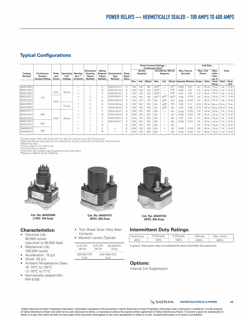
SAFRAN ELECTRICAL & POWER 3332 LABINAL POWER SYSTEMS TF300-9E
POWER RELAYS — HERMETICALLY SEALED - 100 AMPS TO 400 AMPS
Typical Configurations
Cat. No. 6042H151SPST, 200 Amp
Cat. No. 6042H153SPST, 300 Amp
Characteristics:• Electrical Life:
50,000 cycles(sea level to 80,000 feet)
• Mechanical Life:100,000 cycles
• Acceleration: 15 g's• Shock: 25 g's• Ambient Temperature Class:
- B -70°C to 125°C- D -70°C to 71°C
• Hermetically sealed/ MIL-PRF-6106
• Twin Break Silver Alloy MainContacts
• Vibration Levels (Typical):
Cat. No. 6042H2863 PST, 100 Amp
Auxiliary switch: SPDT rated 28 Vdc and 115 V 400 Hz, 5 Amp Res. & Ind. & 0.75 Amp Lamp.kRated 100,000 operations electrical and mechanical life. Auxiliary switch rated 1.25 Amp Res. & 0.75 Amp Ind.lRated 50 g shock.mThese ratings for 115 V 400 Hz only.nSee MS Sheets for details.oIntermittent duty ratings for general applications (see chart below).qRatings for 50/60 Hz only @ 115/200 Vac.
5-10 CPS.08 DA
10-5 CPS.06 DA
55-200CPS10 g’s
250-500 CPS5 g’s
500-1500 CPS3 g’s
Intermittent Duty Ratings:Continuous
100%
15 Minutes
130%
5 Minutes
150%1 Minute
200%
Max. Inrush
600%
In general, these power relays can withstand the above intermittent duty overcurrent.
Options:Internal Coil Suppression
Catalog Number
Continuous Ampere
Contact Rating
Poles and
Throw
Operating Coil
Voltage
Number Aux.
Contacts
Dimension Drawing Figure
Number
Wiring Diagram Figure
Number
Government Type
Number
Temp Class/ Note
Power Contact Ratings —Continuous Dutyo
Max. Time In Seconds
Coil Data
Volts28 VdcAmperes
115/200 Vac 400 Hz Amperes
Max. Coil Power
Max. Volts Pick-up @
Res. Ind. Motor Res. Ind. Motor Operate Release Amps Volts Amb Temp.
Hold Drop Out
6042H159-26042H160-26042H166-2
100
SPST 28 Vdc
—1—
—
1
—
1
—
—
1
—
1—
1
111
2
2
2
2
11
1
1
1
11
9109
6
8
8
6
9
10
9
9
10
910
MS24141-D1MS24141-D2MS24182-D1MS24168-D1
MS24168-D2
MS24168-A4
MS24168-A3
MS24142-D1
MS24142-D2
MS24183-D1
MS24184-D1—
——
BBDB
B
D
D
B
B
D
D
D
DD
100100100
100
100
100
100
200
200
200
300
300
400
400
100100100
100
100
100
100
100
100
100
100
100
100
100
100100100
100
100
100
100
200
200
200
250
250
250
250
100m
100m
100m
100m
100
100
100
200
200
200
300
300
400
400
———
50q
50q
50q
50q
—
—
—
—
—
—
—
75m
75m
75m
100m
100
100
100
150
150
150
150
150
150
150
0.0250.0250.02
0.06
0.06
0.06
0.06
0.0350.035
0.03
0.035
0.035
0.035
0.010.010.010.015
0.025
0.11
0.08
0.015
0.015
0.01
0.015
0.015
0.015
0.50.50.5
0.6
0.6
0.25
0.25
0.6
0.6
0.5
0.6
0.6
0.6
0.6
29 dc29 dc29 dc
29 dc
29 dc
120 ac
120 ac
29 dc
29 dc
29 dc
29 dc
29 dc
29 dc
29 dc
18 dc18 dc18 dc
18 dc
18 dc
90 ac
90 ac
18 dc
18 dc
18 dc
18 dc
18 dc
18 dc
18 dc
7 dc7 dc7 dc7 dc
7 dc
40 ac
40 ac
7 dc
7 dc
7 dc
7 dc
7 dc
7 dc
7 dc
1.5 dc1.5 dc1.5 dc1.5 dc
1.5 dc
10 ac
10 ac
1.5 dc
1.5 dc
1.5 dc
1.5 dc
1.5 dc
1.5 dc
1.5 dc
6042H161-26042H162-2
3PST6042H286-26042H289-2 115 Vac
6042H151-2
6042H152-2
6042H167-2
200
SPST 28 Vdc6042H153-26042H154-2 300
SM400H2-2SM400H3-2 400
“Safran Electrical & Power Proprietary Information. Information contained in this document is Safran Electrical & Power Proprietary Information and is disclosed in confidence. It is the property of Safran Electrical & Power and shall not be used, disclosed to others, or reproduced without the express written agreement of Safran Electrical & Power. If consent is given for reproduction in whole or in part, this notice set forth on each page of this document shall appear in any such reproduction in whole or in part. Unauthorized export or re-export is prohibited.”
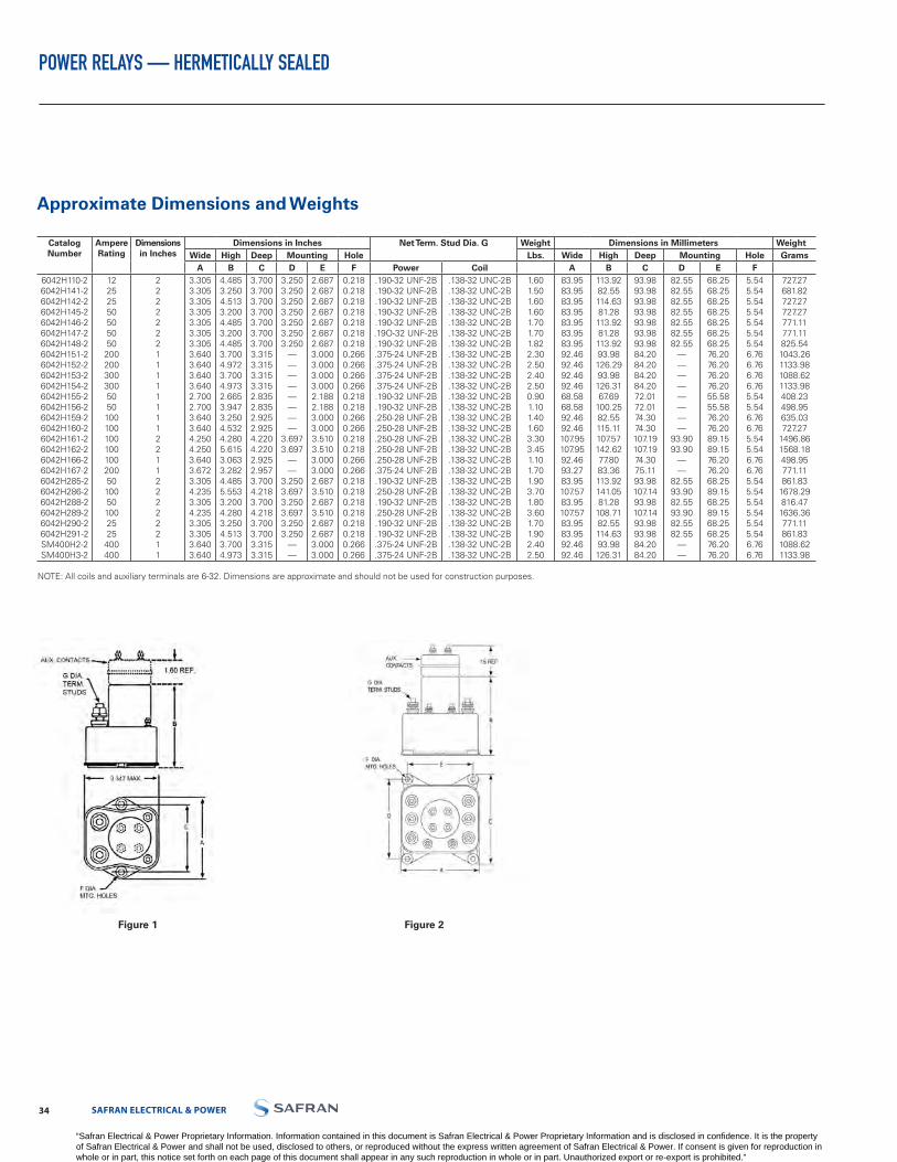
LABINAL POWER SYSTEMS TF300-9E 3534 SAFRAN ELECTRICAL & POWER
POWER RELAYS — HERMETICALLY SEALED
Figure 1 Figure 2
Catalog Number
Ampere Rating
Dimensions in Inches
Dimensions in Inches Net Term. Stud Dia. G Weight Dimensions in Millimeters WeightWide High Deep Mounting Hole Lbs. Wide High Deep Mounting Hole Grams
A B C D E F Power Coil A B C D E F6042H110-26042H141-26042H142-26042H145-26042H146-26042H147-26042H148-26042H151-26042H152-26042H153-26042H154-26042H155-26042H156-26042H159-26042H160-26042H161-26042H162-26042H166-26042H167-26042H285-26042H286-26042H288-26042H289-26042H290-26042H291-2SM400H2-2SM400H3-2
12252550505050
200200300300505010010010010010020050100501002525
400400
222222211111111221122222211
3.3053.3053.3053.3053.3053.3053.3053.6403.6403.6403.6402.7002.7003.6403.6404.2504.2503.6403.6723.3054.2353.3054.2353.3053.3053.6403.640
4.4853.2504.5133.2004.4853.2004.4853.7004.9723.7004.9732.6653.9473.2504.5324.2805.6153.0633.2824.4855.5533.2004.2803.2504.5133.7004.973
3.7003.7003.7003.7003.7003.7003.7003.3153.3153.3153.3152.8352.8352.9252.9254.2204.2202.9252.9573.7004.2183.7004.2183.7003.7003.3153.315
3.2503.2503.2503.2503.2503.2503.250
————————
3.6973.697
——
3.2503.6973.2503.6973.2503.250
——
2.6872.6872.6872.6872.6872.6872.6873.0003.0003.0003.0002.1882.1883.0003.0003.5103.5103.0003.0002.6873.5102.6873.5102.6872.6873.0003.000
0.2180.2180.2180.2180.2180.2180.2180.2660.2660.2660.2660.2180.2180.2660.2660.2180.2180.2660.2660.2180.2180.2180.2180.2180.2180.2660.266
.190-32 UNF-2B
.190-32 UNF-2B
.190-32 UNF-2B
.190-32 UNF-2B
.190-32 UNF-2B.19O-32 UNF-2B.190-32 UNF-2B.375-24 UNF-2B.375-24 UNF-2B.375-24 UNF-2B.375-24 UNF-2B.190-32 UNF-2B.190-32 UNF-2B.250-28 UNF-2B.250-28 UNF-2B.250-28 UNF-2B.250-28 UNF-2B.250-28 UNF-2B.375-24 UNF-2B.190-32 UNF-2B.250-28 UNF-2B.190-32 UNF-2B.250-28 UNF-2B.190-32 UNF-2B.190-32 UNF-2B.375-24 UNF-2B.375-24 UNF-2B
.138-32 UNC-2B
.138-32 UNC-2B
.138-32 UNC-2B
.138-32 UNC-2B
.138-32 UNC-2B
.138-32 UNC-2B
.138-32 UNC-2B
.138-32 UNC-2B
.138-32 UNC-2B
.138-32 UNC-2B
.138-32 UNC-2B
.138-32 UNC-2B
.138-32 UNC-2B
.138-32 UNC-2B
.138-32 UNC-2B
.138-32 UNC-2B
.138-32 UNC-2B
.138-32 UNC-2B
.138-32 UNC-2B
.138-32 UNC-2B
.138-32 UNC-2B
.138-32 UNC-2B
.138-32 UNC-2B
.138-32 UNC-2B
.138-32 UNC-2B
.138-32 UNC-2B
.138-32 UNC-2B
1.601.501.601.601.701.701.822.302.502.402.500.901.101.401.603.303.451.101.701.903.701.803.601.701.902.402.50
83.9583.9583.9583.9583.9583.9583.9592.4692.4692.4692.4668.5868.5892.4692.46107.95107.9592.4693.2783.95107.5783.95107.5783.9583.9592.4692.46
113.9282.55114.6381.28113.9281.28113.9293.98126.2993.98126.3167.69
100.2582.55115.11107.57142.6277.8083.36113.92141.0581.28
108.7182.55114.6393.98126.31
93.9893.9893.9893.9893.9893.9893.9884.2084.2084.2084.2072.0172.0174.3074.30107.19107.1974.3075.1193.98107.1493.98107.1493.9893.9884.2084.20
82.5582.5582.5582.5582.5582.5582.55
————————
93.9093.90
——
82.5593.9082.5593.9082.5582.55
——
68.2568.2568.2568.2568.2568.2568.2576.2076.2076.2076.2055.5855.5876.2076.2089.1589.1576.2076.2068.2589.1568.2589.1568.2568.2576.2076.20
5.545.545.545.545.545.545.546.766.766.766.765.545.546.766.765.545.546.766.765.545.545.545.545.545.546.766.76
727.27681.82727.27727.27771.11771.11825.541043.261133.981088.621133.98408.23498.95635.03727.27
1496.861568.18498.95771.11861.83
1678.29816.47
1636.36771.11861.83
1088.621133.98
NOTE: All coils and auxiliary terminals are 6-32. Dimensions are approximate and should not be used for construction purposes.
Approximate Dimensions and Weights
“Safran Electrical & Power Proprietary Information. Information contained in this document is Safran Electrical & Power Proprietary Information and is disclosed in confidence. It is the property of Safran Electrical & Power and shall not be used, disclosed to others, or reproduced without the express written agreement of Safran Electrical & Power. If consent is given for reproduction in whole or in part, this notice set forth on each page of this document shall appear in any such reproduction in whole or in part. Unauthorized export or re-export is prohibited.”
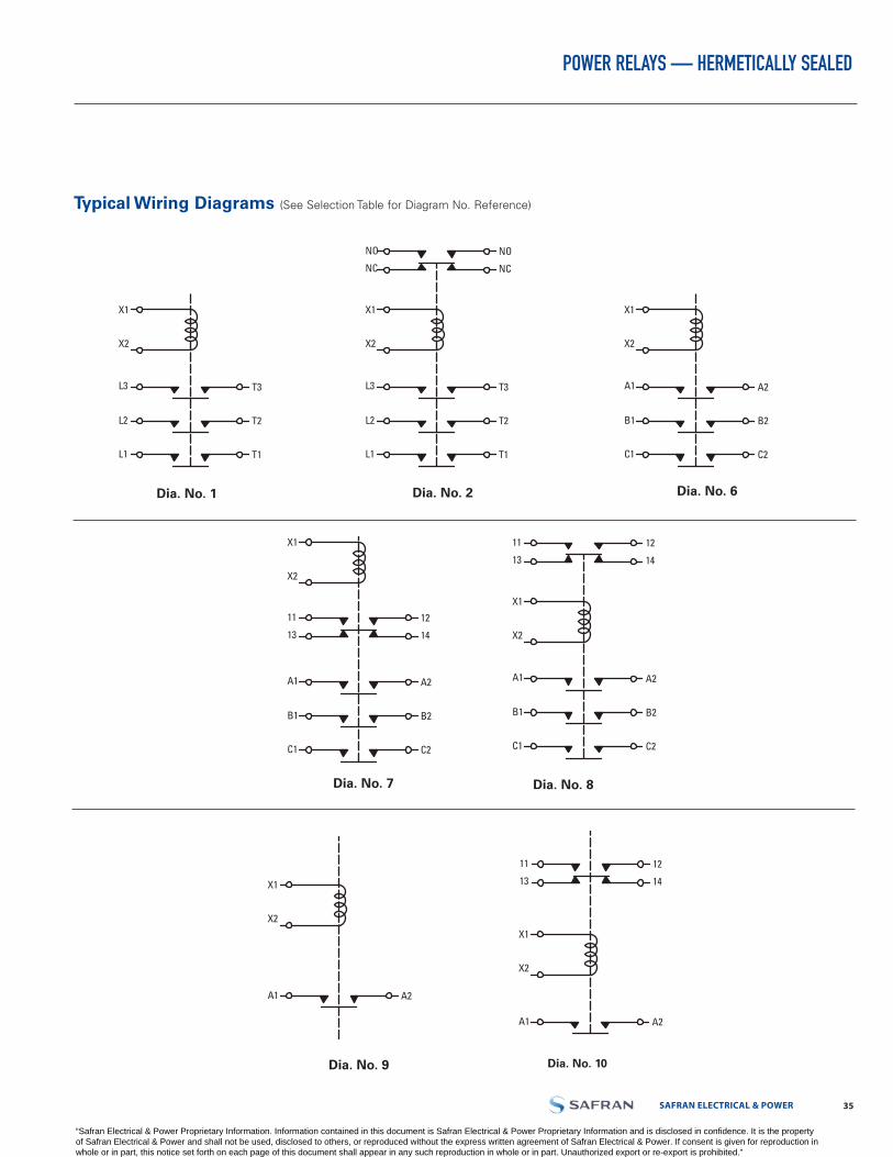
SAFRAN ELECTRICAL & POWER 3534 LABINAL POWER SYSTEMS TF300-9E
POWER RELAYS — HERMETICALLY SEALED
Typical Wiring Diagrams (See Selection Table for Diagram No. Reference)
Dia. No. 7 Dia. No. 8
Dia. No. 9 Dia. No. 10
Dia. No. 6Dia. No. 2Dia. No. 1
X2
X1
T3L3
T2L2
T1L1
X2
X1
A2A1
B2B1
C2C1
X2
X1
T3L3
T2L2
T1L1
NCNC
NONO
X2
X1
A2A1
B2B1
C2C1
1413
1211
X2
X1
A2A1
B2B1
C2C1
1413
1211
X2
X1
A2A1
1413
1211
X2
X1
A2A1
X2
X1
CA2A1
CB2B1
CC2C1
1413
1211
X2
X1
T3L3
T2L2
T1L1
X2
X1
A2A1
B2B1
C2C1
X2
X1
T3L3
T2L2
T1L1
NCNC
NONO
X2
X1
A2A1
B2B1
C2C1
1413
1211
X2
X1
A2A1
B2B1
C2C1
1413
1211
X2
X1
A2A1
1413
1211
X2
X1
A2A1
X2
X1
CA2A1
CB2B1
CC2C1
1413
1211
X2
X1
T3L3
T2L2
T1L1
X2
X1
A2A1
B2B1
C2C1
X2
X1
T3L3
T2L2
T1L1
NCNC
NONO
X2
X1
A2A1
B2B1
C2C1
1413
1211
X2
X1
A2A1
B2B1
C2C1
1413
1211
X2
X1
A2A1
1413
1211
X2
X1
A2A1
X2
X1
CA2A1
CB2B1
CC2C1
1413
1211
X2
X1
T3L3
T2L2
T1L1
X2
X1
A2A1
B2B1
C2C1
X2
X1
T3L3
T2L2
T1L1
NCNC
NONO
X2
X1
A2A1
B2B1
C2C1
1413
1211
X2
X1
A2A1
B2B1
C2C1
1413
1211
X2
X1
A2A1
1413
1211
X2
X1
A2A1
X2
X1
CA2A1
CB2B1
CC2C1
1413
1211
X2
X1
T3L3
T2L2
T1L1
X2
X1
A2A1
B2B1
C2C1
X2
X1
T3L3
T2L2
T1L1
NCNC
NONO
X2
X1
A2A1
B2B1
C2C1
1413
1211
X2
X1
A2A1
B2B1
C2C1
1413
1211
X2
X1
A2A1
1413
1211
X2
X1
A2A1
X2
X1
CA2A1
CB2B1
CC2C1
1413
1211
“Safran Electrical & Power Proprietary Information. Information contained in this document is Safran Electrical & Power Proprietary Information and is disclosed in confidence. It is the property of Safran Electrical & Power and shall not be used, disclosed to others, or reproduced without the express written agreement of Safran Electrical & Power. If consent is given for reproduction in whole or in part, this notice set forth on each page of this document shall appear in any such reproduction in whole or in part. Unauthorized export or re-export is prohibited.”

LABINAL POWER SYSTEMS TF300-9E 3736 SAFRAN ELECTRICAL & POWER
POWER RELAYS — TERMINAL COVERS FOR HERMETICALLY SEALED POWER RELAYS
Specifications
• Molded of unbreakable nylon• Ambient temperature ranges:
-70°C to 125°C• Secured by coil terminal
hardware
• Part number molded intocover
• Positive protection betweenpower stubs
Part No. 49-2667MS27243-3
Part No. 49-2672MS27243-5
Part No. 49-2661MS27243-1
Part No. 49-2665MS27242-1
Part No. 49-2670MS27243-4
“Safran Electrical & Power Proprietary Information. Information contained in this document is Safran Electrical & Power Proprietary Information and is disclosed in confidence. It is the property of Safran Electrical & Power and shall not be used, disclosed to others, or reproduced without the express written agreement of Safran Electrical & Power. If consent is given for reproduction in whole or in part, this notice set forth on each page of this document shall appear in any such reproduction in whole or in part. Unauthorized export or re-export is prohibited.”
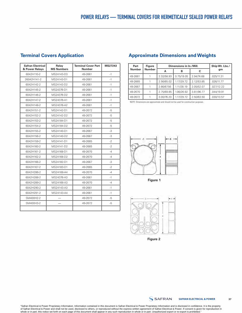
SAFRAN ELECTRICAL & POWER 3736 LABINAL POWER SYSTEMS TF300-9E
POWER RELAYS — TERMINAL COVERS FOR HERMETICALLY SEALED POWER RELAYS
Terminal Covers Application Approximate Dimensions and Weights
Figure 1
Figure 2
Safran Electrical & Power Relays
RelayMS Numbers
Terminal Cover Part Number
MS27243
6042H110-2 MS24143-D3 49-2661 -1
26042H141-2 MS24143-D1 49-2661 -1
6042H142-2 MS24143-D2 49-2661 -1
6042H145-2 MS24376-D1 49-2661 -1
6042H146-2 MS24376-D2 49-2661 -1
6042H147-2 MS24376-A1 49-2661 -1
6042H148-2 MS24376-A2 49-2661 -1
6042H151-2 MS24142-D1 49-2672 -5
6042H152-2 MS24142-D2 49-2672 -5
6042H153-2 MS24184-D1 49-2672 -5
6042H154-2 MS24184-D2 49-2672 -5
6042H155-2 MS24140-D1 49-2667 -3
6042H156-2 MS24140-D2 49-2667 -3
6042H159-2 MS24141-D1 49-2665 -2
6042H160-2 MS24141-D2 49-2665 -2
6042H161-2 MS24168-D1 49-2670 -4
6042H162-2 MS24168-D2 49-2670 -4
6042H166-2 MS24182-D1 49-2667 -3
6042H167-2 MS24183-D1 49-2665 -2
6042H286-2 MS24168-A4 49-2670 -4
6042H288-2 MS24376-A3 49-2661 -1
6042H289-2 MS24168-A3 49-2670 -4
6042H290-2 MS24143-A3 49-2661 -1
6042H291-2 MS24143-A4 49-2661 -1
SM400H2-2 — 49-2672 -5
SM400H3-2 — 49-2672 -5
PartNumber
Figure Number
Dimensions in In./Mill. Ship Wt. Lbs./gm
A B C
49-2661 1 2.32/58.93 0.75/19.05 2.94/74.68 .025/11.31
49-2665 1 2.56/65.02 1.17/29.72 2.12/53.85 .026/11.77
49-2667 1 2.66/67.56 1.11/28.19 2.05/52.07 .027/12.22
49-2670 1 2.75/69.85 1.06/26.92 3.81/96.77 .044/19.91
49-2672 1 3.00/76.20 1.17/29.72 2.50/63.50 .030/13.57
NOTE: Dimensions are approximate and should not be used for construction purposes.
“Safran Electrical & Power Proprietary Information. Information contained in this document is Safran Electrical & Power Proprietary Information and is disclosed in confidence. It is the property of Safran Electrical & Power and shall not be used, disclosed to others, or reproduced without the express written agreement of Safran Electrical & Power. If consent is given for reproduction in whole or in part, this notice set forth on each page of this document shall appear in any such reproduction in whole or in part. Unauthorized export or re-export is prohibited.”

POWER RELAYS — HERMATICALLY SEALED LIGHT-WEIGHT - SM100H1
Engineering Data
• MIL-R-6106 Type I- Hermetically Sealed- Continuous Duty
• Weight - 11.3 oz. (320 grams)• Seal - 1x10⁻⁶ STD CC/SEC
Max• Altitude: 80,000 Feet• Double Break Contacts
Selection Table
(4) #8 (.164) - 32UNJC-3A SCREWCAPTIVE, HEX HEAD
(4) RETAINING RING, CRIMP-ON STYLE
• SM100H1
• M6106/48-001
• SM100H15
• M6106/48-002
Application Notes
The curve shows a typical motor/generator requirement. The SM100H1 can withstand up to 400 Amps for several seconds during motor start - dropping to 100 Amps within 5 seconds. The SM100H1 can withstand the generator output up to 200 Amp for several minutes - dropping to 100 Amps within 3.5 minutes. These cycles can be repeated once every 90 seconds. The SM100H1 will meet applications requiring a reliable and robust contactor.
Vibration Random 15 Minutes Each
Plane
M6106/48-001
Frequency (Hz) Level (g^2/Hz)
10 - 125 0.037
125 - 250 +4 dB
250 - 1000 0.1
1000 - 2000 -3 dB
Vibration Random 15 Minutes Each Plane
M6106/48-002
Frequency (Hz) Level (g^2/Hz)
15 - 50 0.012
120 - 200 0.364
250 - 400 0.194
600 - 1000 0.060
1300 - 2000 0.097
Test to be performed with 5 ampere load on main contact.
DC - Motor start (seconds)Normally twice per flight
400
300
AMPE
RES
200
100
5 10SECONDS / MINUTES
150
Battery charge (minutes)Normally twice per flight
38 SAFRAN ELECTRICAL & POWER
“Safran Electrical & Power Proprietary Information. Information contained in this document is Safran Electrical & Power Proprietary Information and is disclosed in confidence. It is the property of Safran Electrical & Power and shall not be used, disclosed to others, or reproduced without the express written agreement of Safran Electrical & Power. If consent is given for reproduction in whole or in part, this notice set forth on each page of this document shall appear in any such reproduction in whole or in part. Unauthorized export or re-export is prohibited.”
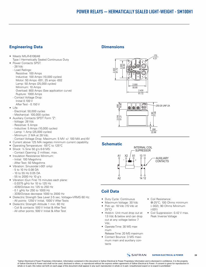
POWER RELAYS — HERMATICALLY SEALED LIGHT-WEIGHT - SM100H1
Engineering Data
• Meets MIL-R-6106/48Type I Hermetically Sealed Continuous Duty
• Power Contacts SPST:- 28 Vdc- Load Ratings:
Resistive: 100 AmpsInductive: 100 Amps (10,000 cycles)Motor: 50 Amps -001; 25 amps -002Lamp: 50 Amps (25,000 cycles)Minimum: 10 AmpsOverload: 800 Amps (See application curve)Rupture: 1000 Amps
- Contact Voltage Drop:Initial 0.100 VAfter Test - 0.150 V
• Life:- Electrical: 50,000 cycles- Mechanical: 100,000 cycles
• Auxiliary Contacts SPDT Form "Z":- Voltage: 28 Vdc- Resistive: 5 Amps- Inductive: 5 Amps (10,000 cycles)- Lamp: 1 Amp (25,000 cycles)- Minimum: 2 MA at 28 Vdc.- Contact Voltage Drop: Maximum: 5 MV +/- 100 MA and 6V
• Current above 125 MA negates minimum current capability.• Operating Temperature: -55°C to 125°C• Shock: ½ Sine 50 g's 6-9 MS:
- Contact Opening: 2 millisec. max.• Insulation Resistance Minimum:
- Initial: 100 Megohms- After Test: 50 Megohms
• Vibration: Sinusoidal (-001 only)- 5 to 10 Hz 0.08 DA- 10 to 55 Hz 0.05 DA- 55 to 2000 Hz 10 g's
• Vibration (Gun Fire) 15 minutes each plane:- 0.0375 g/Hz for 10 to 125 Hz- 4DB/Octave inc 125 to 250 Hz- 0.1 g/Hz for 250 to 1000 Hz- 3DB/Octave decrease 1000 to 2000 Hz
• Dielectric Strength Sea Level 2-5 sec. Voltage=VRMS 60 Hz:- All points: 1250 V Initial, 1000 V After Tests
• Dielectric Strength Altitude 1 min. 60 Hz:- Coil & contacts: 500 V Initial & After Test- All other points: 500 V Initial & After Test
• Duty Cycle: Continuous• Maximum Voltage: 30 Vdc• Pick up: 18 Vdc (15 Vdc at
25°C)• Hold-in: Unit must drop out at
1.5 Vdc & below and can dropout at any voltage below 7Vdc.
• Operate Time: 30 MS max- mum
Release Time: 20 MS maximum• Contact Bounce: 3 MS maxi- mum main and auxiliary con- tacts
• Coil Resistance:@-25°C; 100 Ohms minimum(- 002); 90 Ohms Minimum(-001)
• Coil Suppression: 0.42 V max.Peak Inverse Voltage
Dimensions
Schematic
Coil Data
.250-28 UNF-2A
.09022.86
2.90
77.66
.656
16.66
2.00050.80
.1704.31
2.000
50.80
2.43061.72
2.430
61.72
2.016
51.21
INTERNAL COILSUPRESSOR
AUXILIARYCONTACTS
X2 X1A1 13 11
A2 14 12
SAFRAN ELECTRICAL & POWER 39
“Safran Electrical & Power Proprietary Information. Information contained in this document is Safran Electrical & Power Proprietary Information and is disclosed in confidence. It is the property of Safran Electrical & Power and shall not be used, disclosed to others, or reproduced without the express written agreement of Safran Electrical & Power. If consent is given for reproduction in whole or in part, this notice set forth on each page of this document shall appear in any such reproduction in whole or in part. Unauthorized export or re-export is prohibited.”

LABINAL POWER SYSTEMS TF300-9E 4140 SAFRAN ELECTRICAL & POWER
POWER RELAYS — ENVIRONMENTALLY SEALED LIGHTWEIGHT - SM15 SERIES
Engineering Data
• Meets MIL-R-6106 Type IV• Weight: 10.5 ounces (284 g)• Altitude:
-Rated: 50,000 feet-Extended: 80,000 feetwith encapsulated terminals
• Ratings:-Voltage: 115/200 V, 400 Hz, 3Æ -Load Ratings:
Resistive: 60 AmpsInductive: 60 AmpsMotor: 40 AmpsMinimum Current: 4 AmpsRupture: 400 Amps
• Environmental Seal: MIL-STD-202, METHOD 112 TestCondition C Procedure IV
• Seal: 6 x 10⁻⁴ STD CC/SEC
• Economizer Coil: 30 Vdc- Inrush: 1.25 Amps(20 milliseconds max)-Steady State: 0.25 Amps
Typical Wiring Digrams
3 P.S.T. - N.C.Auxiliary Contact
115/200 Vac 400 Hz 28 Vdc• Resistive 60 A. 20 A.• Inductive 60 A. 10 A.• Motor 40 A. ….• Minimum Current 4 A. ….• Rupture 400 A. ….• Contact Drop
- Initial 0.150 V Max. ….- After Life Test 0.175 V. Max. ….
• Contact Bounce 2 Milliseconds
DC ratings are maximum overload capability. By wiring two poles in series, 28Vdc rating can be increased to the same as the full AC ratings.
Options• AC operated coils• Encapsulated terminals• Internal coil suppression• Suitable for synchronized power supplied transfer
Power Contact Ratings (Continuous Duty)
Selection Table
3 P.S.T. - N.C.Auxiliary Contact
3 P.D.T. WithoutAuxiliary Contact
3 P.DT. WithAuxiliary Contact
3 P.S.T. N.O. WithoutAuxiliary Contact With
Internal Coil Suppression
X1 (+)X2 (-)
A3
B3
C3
A2
B2
C2
X1 (+)X2 (-)
A3
B3
C3
A3
B3
C3
121113
X1 (+)X2 (-)
A3A1 A2
B3B1 B2
C3C1 C2
X1 (+)X2 (-)
A3A1 A2
B3B1 B2
C3C1 C2
121113
X1 (+)X2 (-)
A1 A2
B1 B2
C1 C2
Poles andThrow-Circuit
Number of AuxiliaryContacts 1 P.D.T.
Government TypeNumber M6106
CatalogNumber
3 P.S.T.-N.O. —1
/10-001 /10-002
SM15AWD1SM15AXD1
3 P.S.T.-N.C. —1
/11-001 /11-002
SM15BWD1SM15BXD1
3 P.D.T. —1
/9-001 /9-002
SM15CWD1SM15CXD1
3 P.S.T.-N.O. — 10-005* SM15AWD3* Unit supplied with internal coil suppression. 45 V max. peak inverse voltage.
“Safran Electrical & Power Proprietary Information. Information contained in this document is Safran Electrical & Power Proprietary Information and is disclosed in confidence. It is the property of Safran Electrical & Power and shall not be used, disclosed to others, or reproduced without the express written agreement of Safran Electrical & Power. If consent is given for reproduction in whole or in part, this notice set forth on each page of this document shall appear in any such reproduction in whole or in part. Unauthorized export or re-export is prohibited.”

SAFRAN ELECTRICAL & POWER 4140 LABINAL POWER SYSTEMS TF300-9E
POWER RELAYS — ENVIRONMENTALLY SEALED LIGHTWEIGHT - SM15 SERIES
Engineering Data
Specifications• Meets MIL-R-6106/9, /10, /11 Type IV Environmentally Sealed
- Continuous Duty Operation• Power Contacts 400 Hz:
- Voltage: 115 V Single Phase115 V/ 200 V Three Phase
- Load Ratings per Pole: Resistive: 60 Amps Inductive: 60 Amps Motor: 40 Amps
Minimum Current: 4 Amps Overload: 320 Amps Rupture: 400 Amps
- Electrical Life at Rated Loads: 100,000 operations (50,000 motor)- Mechanical Life at 15 Amps: 200,000 operations
• Auxiliary Contacts 115 V 400 Hz/ 28 Vdc:- Resistive: 3 Amps- Inductive: 1.5 Amps- Mechanical: 0.5 Amps
• Operating Temperature: -55°C to 71°C• Shock: ½ Sine, 25 g's 6 to 9 MS
- Contact Opening: 1 millisecond maximum• Acceleration: 15 g's• Insulation Resistance Minimum
- Initial: 200 Megohms- After Test: 100 Megohms
• Vibration:- 5 to 10 Hz 0.08" DA- 10 to 55 Hz 0.06" DA- 55 to 400 Hz 10 g's- 400 to 800 Hz 8 g's- 800 to 2000 Hz 8 g's (-55°C to 25°C) 7 g's at 71°
• Dielectric Strength Sea Level 2-5 sec. 60 Hz:- Coil & Auxiliary Contacts: 1250 V Initial, 1000 V After Test,Across open power contacts: 1250 V Initial 625 V After Life.- All Other Points: 1800 V Initial, 1350 V After Test
• Dielectric Strength Altitude 1 minute 60 Hz:- Coil & Auxiliary Contacts: 500 V Initial & After Test- All Other Points: 700 V Initial & After Test
Coil Data• 28 Vdc: Inrush 1.25 Amps (20 MS Max); Steady State 0.25 Amps• Pick-up: 17 Vdc. Hold in: 7.0 Vdc
Drop-out: 1.5 Vdc Unit must drop out at 1.5 Vdc and below andcan drop out at any voltage below 7 Vdc.
• Operate Time: 25 MS. Release Time: 25 MS• Contact Bounce: 2 MS maximum main and auxiliary contacts
Dimensions DrawingsTop View - SM15CXD1 3PDT and Auxiliary Contacts
Top View - SM15AWD1 3 PST N.O. Contacts. Without Auxiliary Contacts
Side View
X2
X1
1.375(34.93)
A1 B1 C1
A2 B2 C2
.240 R.(6.096)
2.313
(58.7
5)
NAMEPLATE CIRCUITPLATE
1.890
(48.0
1)
2.125
(53.9
8)
.475(12.07)
UPPER ANDLOWER BARRIERS
2.500
(63.5
0)
3.032
(77.0
1)
A2
2.40(60.96)
.60(5.24)
A3 B3 C3
A1 B1 C1
13
1211
.240 R.(6.096)
1.06
(26.9
2)
.148(3.76)
DIA.4 MTG. HOLES
1.900
(48.2
6)
2.313
(50.7
5)
Power Terminals.190-32 UNF-2A
SM15CXDI 3PDTand AuxiliaryContacts
“Safran Electrical & Power Proprietary Information. Information contained in this document is Safran Electrical & Power Proprietary Information and is disclosed in confidence. It is the property of Safran Electrical & Power and shall not be used, disclosed to others, or reproduced without the express written agreement of Safran Electrical & Power. If consent is given for reproduction in whole or in part, this notice set forth on each page of this document shall appear in any such reproduction in whole or in part. Unauthorized export or re-export is prohibited.”
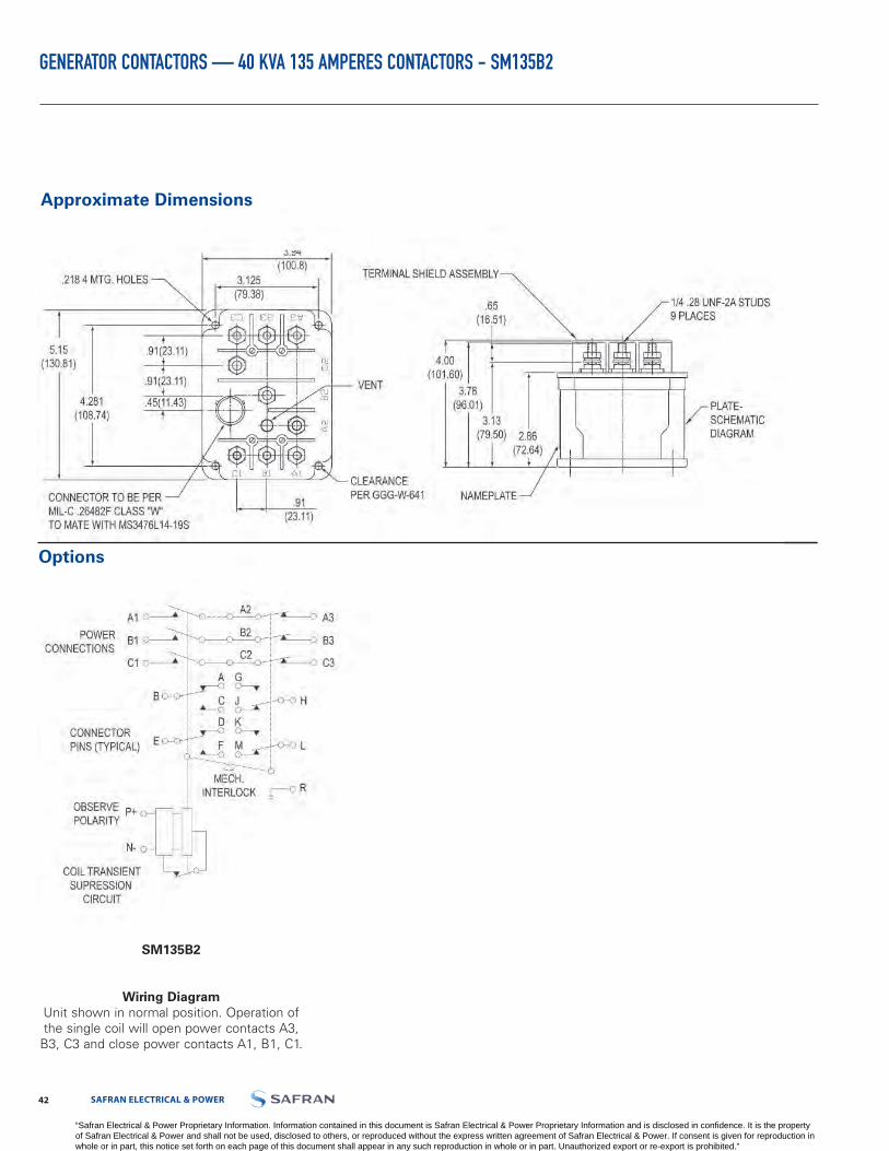
LABINAL POWER SYSTEMS TF300-9E 4342 SAFRAN ELECTRICAL & POWER
GENERATOR CONTACTORS — 40 KVA 135 AMPERES CONTACTORS - SM135B2
Approximate Dimensions
Options
SM135B2
Wiring Diagram
Unit shown in normal position. Operation of the single coil will open power contacts A3,
B3, C3 and close power contacts A1, B1, C1.
“Safran Electrical & Power Proprietary Information. Information contained in this document is Safran Electrical & Power Proprietary Information and is disclosed in confidence. It is the property of Safran Electrical & Power and shall not be used, disclosed to others, or reproduced without the express written agreement of Safran Electrical & Power. If consent is given for reproduction in whole or in part, this notice set forth on each page of this document shall appear in any such reproduction in whole or in part. Unauthorized export or re-export is prohibited.”
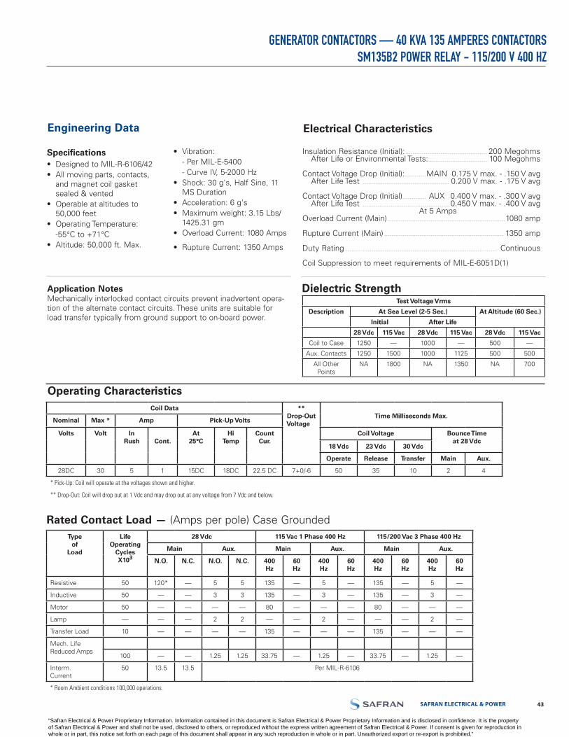
SAFRAN ELECTRICAL & POWER 4342 LABINAL POWER SYSTEMS TF300-9E
GENERATOR CONTACTORS — 40 KVA 135 AMPERES CONTACTORSSM135B2 POWER RELAY - 115/200 V 400 HZ
Electrical CharacteristicsEngineering Data
Specifications• Designed to MIL-R-6106/42• All moving parts, contacts,
and magnet coil gasketsealed & vented
• Operable at altitudes to50,000 feet
• Operating Temperature:-55°C to +71°C
• Altitude: 50,000 ft. Max.
• Vibration:- Per MIL-E-5400- Curve IV, 5-2000 Hz
• Shock: 30 g's, Half Sine, 11MS Duration
• Acceleration: 6 g's• Maximum weight: 3.15 Lbs/
1425.31 gm• Overload Current: 1080 Amps
• Rupture Current: 1350 Amps
Insulation Resistance (Initial): 200 Megohms After Life or Environmental Tests: 100 Megohms
Contact Voltage Drop (Initial): MAIN 0.175 V max. - .150 V avg After Life Test 0.200 V max. - .175 V avg
Contact Voltage Drop (Initial) AUX 0.400 V max. - .300 V avgAfter Life Test 0.450 V max. - .400 V avg
At 5 AmpsOverload Current (Main) 1080 amp
Rupture Current (Main) 1350 amp
Duty Rating Continuous
Coil Suppression to meet requirements of MIL-E-6051D(1)
Application NotesMechanically interlocked contact circuits prevent inadvertent opera-tion of the alternate contact circuits. These units are suitable for load transfer typically from ground support to on-board power.
Dielectric StrengthTest Voltage Vrms
Description At Sea Level (2-5 Sec.) At Altitude (60 Sec.)
Initial After Life
28 Vdc 115 Vac 28 Vdc 115 Vac 28 Vdc 115 Vac
Coil to Case 1250 — 1000 — 500 —
Aux. Contacts 1250 1500 1000 1125 500 500
All Other Points
NA 1800 NA 1350 NA 700
Operating CharacteristicsCoil Data **
Drop-OutVoltage
Time Milliseconds Max.Nominal Max * Amp Pick-Up Volts
Volts Volt InRush Cont.
At25°C
HiTemp
CountCur.
Coil Voltage Bounce Timeat 28 Vdc
18 Vdc 23 Vdc 30 Vdc
Operate Release Transfer Main Aux.
28DC 30 5 1 15DC 18DC 22.5 DC 7+0/-6 50 35 10 2 4
* Pick-Up: Coil will operate at the voltages shown and higher.
** Drop-Out: Coil will drop out at 1 Vdc and may drop out at any voltage from 7 Vdc and below.
Rated Contact Load — (Amps per pole) Case GroundedType
ofLoad
LifeOperating
CyclesX103
28 Vdc 115 Vac 1 Phase 400 Hz 115/200 Vac 3 Phase 400 Hz
Main Aux. Main Aux. Main Aux.
N.O. N.C. N.O. N.C. 400Hz
60Hz
400Hz
60Hz
400Hz
60Hz
400Hz
60Hz
Resistive 50 120* — 5 5 135 — 5 — 135 — 5 —
Inductive 50 — — 3 3 135 — 3 — 135 — 3 —
Motor 50 — — — — 80 — — — 80 — — —
Lamp — — — 2 2 — — 2 — — — 2 —
Transfer Load 10 — — — — 135 — — — 135 — — —
Mech. LifeReduced Amps
100 — — 1.25 1.25 33.75 — 1.25 — 33.75 — 1.25 —
Interm.Current
50 13.5 13.5 Per MIL-R-6106
* Room Ambient conditions 100,000 operations.
“Safran Electrical & Power Proprietary Information. Information contained in this document is Safran Electrical & Power Proprietary Information and is disclosed in confidence. It is the property of Safran Electrical & Power and shall not be used, disclosed to others, or reproduced without the express written agreement of Safran Electrical & Power. If consent is given for reproduction in whole or in part, this notice set forth on each page of this document shall appear in any such reproduction in whole or in part. Unauthorized export or re-export is prohibited.”

LABINAL POWER SYSTEMS TF300-9E 4544 SAFRAN ELECTRICAL & POWER
FLAT PACKS — CUSTOM CAPABILITY
Engineering Data
• Construction: Gasket Sealed (vented) -MIL - R - 6106 Type III, except as noted
• Ratings:- Main Contacts
Configuration: SPST N.O.Voltage (Nominal): 28 Vdc
CurrentResistive: 400 Amp (Terminal Temperature
Rise 85°C above 71°C Ambient)Inductive: 100 AmpsMotorload: 400 AmpsOverload: 2,000 AmpsCustom Motor Current: See Graph 20,000 cycles (Min.)Motor Current test to be run 5 cycles per hour maximum with 90 seconds off time between cycles
• Life:Electrical: 50,000 Cycles MinimumMechanical: 100,000 Cycles
- Weight: (Max.): 2.25 Lbs/ 1020.58 gm• Environmental Data
Ambient Temp: -55°C to +71°CAltitude: 50,000 Feet Maximum
- Vibration: 5 to 14 Hz 0.2" Double Amplitude14 to 33 Hz 2 g33 to 52 Hz 0.036"Double Amplitude52 to 500 Hz 5 g (peak)
- Acceleration: 12 g Maximum (Steady State Load)- Shock:
G-Level: 25 g'sDuration: 6 to 9 Milliseconds
- Max. Duration Contact 2 MillisecondsOpening
• Coil Data:- Duty Cycle: Continuous, Economizing- Nom. Operating- Voltage: 28 Vdc- Pick-Up Voltage: 18 Vdc Max. at 25°C- Drop-Out Voltage: 0.75-3.50 Vdc at 25°C- Hold Voltage: 9 Vdc- Operating Time: 35 Milliseconds Maximum- Inrush Current: 3.0 Amps Max for 50 Milliseconds
Max. at 25°C- Hold Current: 1.2 Amps Max. at 25°C
• Auxiliary Contacts:- Voltage: 28 Vdc or 115 V, 400 Hz- Current: 5 Amp Resistive
• Low Level Auxiliary Contacts• Auxiliary Terminal Size and
Length
Options
Electronic Control will add coil turns to compensate for low battery voltage during starter operation.
“Safran Electrical & Power Proprietary Information. Information contained in this document is Safran Electrical & Power Proprietary Information and is disclosed in confidence. It is the property of Safran Electrical & Power and shall not be used, disclosed to others, or reproduced without the express written agreement of Safran Electrical & Power. If consent is given for reproduction in whole or in part, this notice set forth on each page of this document shall appear in any such reproduction in whole or in part. Unauthorized export or re-export is prohibited.”
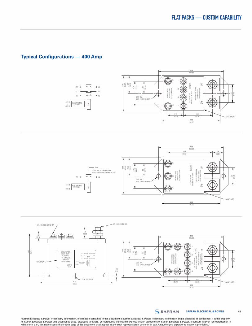
SAFRAN ELECTRICAL & POWER 4544 LABINAL POWER SYSTEMS TF300-9E
FLAT PACKS — CUSTOM CAPABILITY
Typical Configurations — 400 Amp
1211
+X1
-X2
ELECTRONIC CONTROL CO
ILA1 A2
13 14
A2A1
1413
1211
-X2+X1
INS
TALLA
TION
REC
OM
MEN
DED
HIGH VOLTAGE TEST
SHORT +X1 TO -X2 BEF0RECAUTION
INS
TALLA
TION
REC
OM
MEN
DED
TORQUE 19 in-lbs MAX
TORQ
UE 90 in-lbs M
AX.
NAMEPLATE
4.56115.82
4.06103.12
.2666.76
DIA.2 MTG. HOLES
.88
22.3
5
.1.7
544
.45.1
.28
32.5
1
2.56
65.0
2
1.25
31.7
5
2.0050.80
1.1328.70
A2A1
-X2IND
+X1
INS
TALLA
TION
REC
OM
MEN
DED
HIGH VOLTAGE TEST
SHORT +X1 TO -X2 BEF0RECAUTION
INS
TALLA
TION
REC
OM
MEN
DED
TORQUE 19 in-lbs MAX
TORQ
UE 90 in-lbs M
AX.
NAMEPLATE
4.56115.82
3.1379.50
.7819.81
4.06103.12
1.25
31.7
5
A2A1
+X1-X2
2324
1112
1314
INS
TALLA
TION
REC
OM
MEN
DED
HIGH VOLTAGE TESTSHORT +X1 TO -X2 BEF0RE
CAUTION
INS
TALLA
TION
REC
OM
MEN
DED
TORQUE 19 in-lbs MAX
TORQ
UE 90 in-lbs M
AX.
NAMEPLATE
4.56115.82
4.06103.12
1.25
31.7
5
2.0050.80
1.1328.70
3.42
86.8
7
NAMEPLATE
400 AMP S.P.-S.T.28 VDC RELAY28 VDC COIL
NO. SM400D78
FSCM 81640
MADE INU.S.A.
VENT LOCATION5.15
130.81
.5012.70
6 X #10(.190)-32UNF-2A
GR835AAR
.061.52
.7519.05
(2) .375-24UNF-2A
1211
+X1
-X2
ELECTRONIC CONTROL CO
IL
A1 A2
13 14
+X1
-X2
ELECTRONIC
IND
SUPPLIES 28 Vdc POWERFROM MOVEABLE CONTACTS
CONTROL COIL
A1 A2.2666.76
DIA.2 MTG. HOLES
.88
22.3
5
.1.7
544
.45.1
.28
32.5
1
2.56
65.0
2
.2666.76
DIA.2 MTG. HOLES
.88
22.3
5
.1.7
544
.45.1
.28
32.5
1
2.56
65.0
2
“Safran Electrical & Power Proprietary Information. Information contained in this document is Safran Electrical & Power Proprietary Information and is disclosed in confidence. It is the property of Safran Electrical & Power and shall not be used, disclosed to others, or reproduced without the express written agreement of Safran Electrical & Power. If consent is given for reproduction in whole or in part, this notice set forth on each page of this document shall appear in any such reproduction in whole or in part. Unauthorized export or re-export is prohibited.”

LABINAL POWER SYSTEMS TF300-9E 4746 SAFRAN ELECTRICAL & POWER
QUALIFIED PRODUCTS UNDER MILITARY SPECIFICATION — MIL-PRF-6106 AND MIL-PRF-83383
MIL P/N Cross Reference
MIL P/NSafran Electrical & Power P/N Page MIL P/N
Safran Electrical & Power P/N Page MIL P/N
Safran Electrical & Power
P/N Page MIL P/N
SafranElectrical& Power
P/N Page
M6106/9-001 M83383/02-06 SM600BA25A1 3 MS24166-D1 6041H200 19 MS24376-A2 6042H148 24/26
M6106/9-002 M83383/02-07 SM600BA35A1 3 MS24166-D2 6041H201 19 MS24376-A3 6042H288 24/26
M6106/10-001 M83383/02-08 SM600BA40A1 3 MS24168-A3 6042H289 24/26 MS24376-A4 6042H285 24/26
M6106/10-002 M83383/02-09 SM600BA50A1 3 MS24168-A4 6042H286 24/26 MS24376-D1 6042H145 24/26
M6106/10-005 M83383/02-10 SM600BA60A1 3 MS24168-D1 6042H161 24/26 MS24376-D2 6042H146 24/26
M6106/11-001 M83383/02-11 SM600BA75A1 3 MS24168-D2 6042H162 24/26 MS25030-D1B 6046H51 19
M6106/11-002 M83383/02-13 SM600BA100A1 3 MS24171-D1 6041H215 19 MS25031-D1B 6046H53 19
M83383/04-03 SM601BA10A1 3 MS24171-D2 6041H202 19 MS25032-D1 6046H46 19
M83383/04-04 SM601BA15A1 3 MS24172-D1 6041H216 19 MS27242-1 6042H181 24/26
M83383/01-01 M83383/04-05 SM601BA20A1 3 MS24172-D2 6041H203 19 MS27242-2 6042H182 24/26
M83383/01-03 M83383/04-07 SM601BA35A1 3 MS24178-D1 6041H219 19 MS27243-1 49-2661 23
M83383/01-04 M83383/04-08 SM601BA40A1 3 MS27243-2 49-2665 23
M83383/01-05 M83383/04-10 SM601BA60A1 3 MS27243-3 49-2667 23
M83383/01-06 MS24140-D1 6042H155 24/26 MS24182-D1 6042H166 19 MS27243-4 49-2670 23
M83383/01-07 MS24140-D2 6042H156 24/26 MS24183-D1 6042H167 19 MS27243-5 49-2672 23
M83383/01-08 MS24141-D1 6042H159 24/26 MS24184-D1 6042H153 19 MS27243-6 49-3179 23
M83383/01-09 MS24141-D2 6042H160 24/26 MS24184-D2 6042H154 19 MS27997-D1 6042H91 24/26
M83383/01-10 MS24142-D1 6042H151 24/26 MS24185-D1 6041H217 19 MS27997-D2 6042H92 24/26
M83383/01-11
SM15CWD1 36
SM15CXD1 36
SM15AWD1 36
SM15AXD1 36
SM15AWD3 36
SM15BWD1 36
SM15BXD1 36
SM600BA5N1 3
SM600BA10N1 3
SM600BA15N1 3
SM600BA20N1 3
SM600BA25N1 3
SM600BA35N1 3
SM600BA40N1 3
SM600BA50N1 3
SM600BA60N1 3
SM600BA75N1 3 MS24142-D2 6042H152 24/26 MS24185-D2 6041H205 19 19
M83383/01-13 SM600BA100N1 3 MS24143-A3 6042H290 24/26 MS24187-D1 6041H220 19
AN3362 6041H209 -1
M83383/02-01 SM600BA5A1 3 MS24143-A4 6042H291 24/26 MS24187-D2 6041H230 19
M83383/02-03 SM600BA10A1 3 MS24143-D1 6042H141 24/26 MS24192-D1 9565H2 19
M83383/02-04 SM600BA15A1 3 MS24143-D2 6042H142 24/26 MS24193-D1 9565H94 19
M83383/02-05 SM600BA20A1 3 MS24143-D3 6042H110 24/26 MS24376-A1 6042H147 24/26
“Safran Electrical & Power Proprietary Information. Information contained in this document is Safran Electrical & Power Proprietary Information and is disclosed in confidence. It is the property of Safran Electrical & Power and shall not be used, disclosed to others, or reproduced without the express written agreement of Safran Electrical & Power. If consent is given for reproduction in whole or in part, this notice set forth on each page of this document shall appear in any such reproduction in whole or in part. Unauthorized export or re-export is prohibited.”
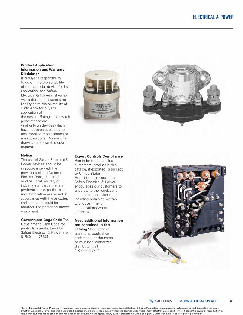
SAFRAN ELECTRICAL & POWER 4746 LABINAL POWER SYSTEMS TF300-9E
ELECTRICAL &
Product Application Information and Warranty DisclaimerIt is buyer’s responsibility to determine the suitability of the particular device for its application, and Safran Electrical & Power makes no warranties, and assumes no liability as to the suitability of sufficiency for buyer’s application of the device. Ratings and switch performance are valid only on devices which have not been subjected to unauthorized modifications or misapplications. Dimensional drawings are available upon request.
NoticeThe use of Safran Electrical & Power devices should be in accordance with the provisions of the National Electric Code, U.L. and/or other local, military or industry standards that are pertinent to the particular end use. Installation or use not in accordance with these codes and standards could be hazardous to personnel and/or equipment.
Government Cage Code The Government Cage Code for products manufactured by Safran Electrical & Power are 81640 and 76374.
Export Controls Compliance Reminder to our catalog customers, product in this catalog, if exported, is subject to United StatesExport Control regulations. Safran Electrical & Power encourages our customers to understand the regulations and ensure compliance, including obtaining written U.S. government authorizations when applicable.
Need additional information not contained in this catalog? For technical questions, application assistance, or the name of your local authorized distributor, call 1-800-955-7354.
POWER
“Safran Electrical & Power Proprietary Information. Information contained in this document is Safran Electrical & Power Proprietary Information and is disclosed in confidence. It is the property of Safran Electrical & Power and shall not be used, disclosed to others, or reproduced without the express written agreement of Safran Electrical & Power. If consent is given for reproduction in whole or in part, this notice set forth on each page of this document shall appear in any such reproduction in whole or in part. Unauthorized export or re-export is prohibited.”

Local contact (Sarasota, FL):SAFRAN ELECTRICAL & POWER2250 Whitfield AvenueSarasota, FL 34243 USATel. 1-800-955-7354 Fax 941-751-7173
SAFRAN ELECTRICAL & POWERHeadquarters : 36 rue Raymond Grimaud 31700 BLAGNAC - FRANCE Tél. +33 (0)5 34 60 00 00 - Fax +33 (0)5 34 60 01 99www.safran-electrical-power.com


![NEW CATALOG LABS - Flame Enterprisesflamecorp.com/PDF/Safran-Electrical-Power/Safran... · 2017. 8. 19. · switch catalog. g2 .0625 [1,59].077 [1,96].430 [10,92] lettering (located](https://static.documents.pub/doc/80x56/6013517c7d0210632c5af545/new-catalog-labs-flame-2017-8-19-switch-catalog-g2-0625-159077-196430.jpg)


