27
DESIGN OF CIVIL STRUCTURES Integrated Solution System for Bridge and Civil Engineering Release Note Release Date : August 2019 Product Ver. : Civil 2020 (v1.1)

DESIGN OF CIVIL STRUCTURES
I n t e g r a t e d S o l u t i o n S y s t e m f o r B r i d g e a n d C i v i l E n g i n e e r i n g
Release Note Release Date : August 2019
Product Ver. : Civil 2020 (v1.1)

Enhancements 1. Maximum Number Limit of Erection Load Cases for Construction Stage Analysis
2. Multiple Modulus of Elasticity for Composite Prestressed Girder
3. Improvement in Prestressed Composite Bridge Wizard: Non-continuous Precast Beam
4. Improvement in Prestressed Composite Bridge Wizard: Diaphragm
5. Bilinear Type Spring Stiffness for Surface Spring Support
6. Force/Stress Contouring based on Center Value of Plate Elements
7. Concurrent Reactions of Moving Load Analysis with respect to Node Local Axis
8. Concurrent Forces of Elastic Links and General Links for Moving Load Analysis
9. Analysis Filtering of Elastic Links and General Links in Moving Load Analysis
10. New Inelastic Hinge Type: Parametric P-M (multi-curve)
11. Precast Section DB: AS
12. Response Spectrum Function: AS 5100.2: 2017
13. User-Defined Drying Basic Shrinkage Strain: AS 5100.5-2017
14. Relaxation of Tendons: AS 5100.5-2017
15. User-Defined Stress Limit for Crack Check: AS 5100.5-2017
16. Dynamic Load Allowance for Expansion Joint: AASHTO LRFD
17. Standard Vehicles: Indiana Department of Transportation
18. Standard Vehicles: Colombian CCP-14
19. Auto-Generation of Load Combination: BS 5400
20. Design Report in Czech
21. Response Spectrum Function: Philippines DPWH-BSDS 2013
22. India Material Database Update
23. IRS Load Combination
24. Prestressed Concrete Design by IRS Concrete Bridge Code

3 / 27
Civil 2020 (v1.1) Release Note Civil 2020
1. Maximum Number Limit of Erection Load Cases for Construction Stage Analysis
Analysis > Analysis Control > Construction Stage
• Maximum limit in the number of erection load cases is increased from 5 to 10.
• More erection loads can be applied during construction stage and the results can be viewed with different erection load cases and hence different load factors in the load combination.
Construction Stage Analysis Control Data

4 / 27
Civil 2020 (v1.1) Release Note Civil 2020
2. Multiple Modulus of Elasticity for Composite Prestressed Girder
Properties > Section > Composite
• The modular ratio between slab concrete and girder concrete can be defined to determine the creep-transformed section properties of the composite section.
• The tendon and reinforcement are not taken into account to calculate the creep-transformed section properties and hence approximate stresses.
Composite PSC section Creep Transformed Section Properties

5 / 27
Civil 2020 (v1.1) Release Note Civil 2020
3. Improvement in Prestressed Composite Bridge Wizard: Non-continuous Precast Beam
Structure > Wizard > Prestressed Composite Bridge
• New option is introduced to apply non-continuous condition for the precast beams between neighboring spans.
• Bending moment is released at the slab connecting two spans.
Precast Composite Girder Bridge Wizard
Continuous condition
Non-continuous condition

6 / 27
Civil 2020 (v1.1) Release Note Civil 2020
4. Improvement in Prestressed Composite Bridge Wizard: Diaphragm
Structure > Wizard > Prestressed Composite Bridge
• Individual diaphragms can be included/excluded in the modeling of prestressed composite girder bridge.
Precast Composite Girder Bridge Wizard
No Diaphragm
No Intermediate Diaphragm

7 / 27
Civil 2020 (v1.1) Release Note Civil 2020
5. Bilinear Type Spring Stiffness for Surface Spring Support
Boundary > Spring Supports > Surface Spring
• Bilinear spring type is added in the Surface Spring Support to simulate the strength limit of the soil. The strength limit should be defined by the user.
• Both Point Spring Support and Elastic Link are supported.
Surface Spring Support
Spring
Strength
(kN)
Horizontal
Displacement (m)
Horizontal Soil Stiffness(kN)
Spring Stiffness (kN/m)
Spring Strength [kN]
= Section Width [m]×Element Length [m]×PHU [kN/m2]

8 / 27
Civil 2020 (v1.1) Release Note Civil 2020
6. Force/Stress Contouring based on Center Value of Plate Elements
Results > Results > Stresses > Plane-Stress/Plate Stresses
• Stresses at the node are determined by the linear interpolation of Gauss points, which often leads to stress exceeding yield stress in the material nonlinear analysis.
• Plate stress contour can now be displayed using the value at the element center instead of element nodes. The center values will not exceed the yield stress.
Without Center Contour option
Yield Stress=340MPa
With Center Contour option
Larger than yield stress Less than yield stress

9 / 27
Civil 2020 (v1.1) Release Note Civil 2020
7. Concurrent Reactions of Moving Load Analysis with respect to Node Local Axis
Result Tables > Concurrent Reaction
• Concurrent reactions due to moving load case can be viewed with respect to node local axis as well as global axis.
• This is useful to check concurrent reactions in the skewed bridges or horizontally curved bridges.
Support and Node Local
axis not parallel to global
axis in the skewed bridge
Concurrent Reaction Group
Concurrent Reaction Table Concurrent Reaction (Local)

10 / 27
Civil 2020 (v1.1) Release Note Civil 2020
8. Concurrent Forces of Elastic Links and General Links for Moving Load Analysis • Concurrent forces of Elastic Links and General Links are provided for the moving load analysis.
• This is useful when the bearings of the bridge are simulated using Elastic links.
Moving Load Analysis Control
Analysis > Analysis Control > Moving Load, Result Tables > Elastic Link, Result Tables > General Link
Concurrent Forces of Elastic Links
Elastic Link Force Table

11 / 27
Civil 2020 (v1.1) Release Note Civil 2020
9. Analysis Filtering of Elastic Links and General Links in Moving Load Analysis
Analysis > Analysis Control > Moving Load
• The user can choose a group of Elastic Links and General Links to be analyzed for the moving load cases.
• This filter option makes the analysis time much shorter when there are a lot of Elastic Links / General Links in the model.
Moving Load Analysis Control
Assign a boundary group
to Elastic Links representing
bearings.
Select the boundary group.
Elastic links assigned to piles are not
computed for moving load analysis.

12 / 27
Civil 2020 (v1.1) Release Note Civil 2020
10. New Inelastic Hinge Type: Parametric P-M (multi-curve)
Properties > Inelastic Properties > Inelastic Hinge
• Parametric P-M (multi-curve) is a new inelastic hinge type described by bending moment vs. curvature relationship which is a function of the axial force.
• Unlike the other types of hinge, the moment vs. curvature relationship can be defined by the user depending on the axial forces.
Inelastic Hinge Properties
• The flexural behavior of the beam element is described by bending
moment vs. curvature relationship. This relationship is input in the
form of multilinear functions. The moment vs. curvature relationship
is a function of the axial force.
• The flexural behavior of the beam element is defined by two bending
vs. curvature relationships, one for each principal plane of inertia.
Interaction between the two bending moments (My and Mz) are not
taken into account.

13 / 27
Civil 2020 (v1.1) Release Note Civil 2020
10. New Inelastic Hinge Type: Parametric P-M (multi-curve) continued
Properties > Inelastic Properties > Inelastic Hinge
• Ultimate positive and negative curvature can be specified.
• This hinge type can be applied to nonlinear static or nonlinear time history analysis.
P-M Multi-Curve Type
• P-M Multi-Curve Type allows for bilinear and multilinear plasticity.
• The first data point corresponds to negative rupture and the last data
point corresponds to positive rupture. One data point – the zero point
– must be at the origin. A different number of data points can be used
for the positive and negative sections of the curve.
• Moment and curvature relationship can depend on the axial force
and the dependence can be different in tension and in compression.
The number of axial forces must be two at least.
• To obtain the bending moment-curvature curve for a level of axial
force not input, interpolation is used. This interpolation is performed,
not on the bending moment-curvature curves, but on the moment-
plastic curvature curves. The moment-plastic curvature curves are
automatically calculated from the bending moment-curvature curves.
• Strain hardening can be isotropic, kinematic or mixed. The moment-
curvature relationship can either be symmetric or non-symmetric.
Whether it is symmetric or non-symmetric, entire moment-curvature
curve should be entered.
14 / 27
Civil 2020 (v1.1) Release Note Civil 2020
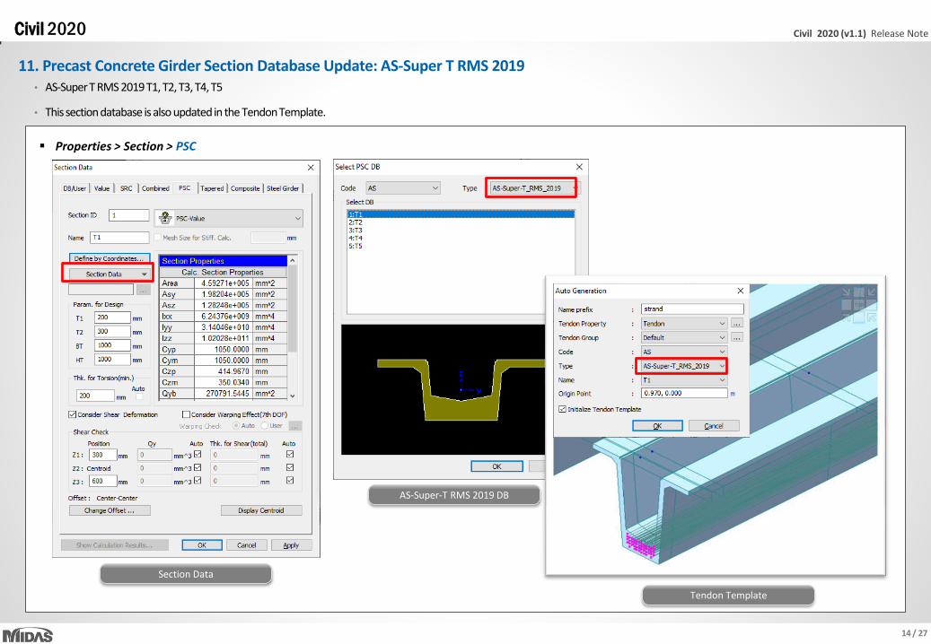
11. Precast Concrete Girder Section Database Update: AS-Super T RMS 2019 • AS-Super T RMS 2019 T1, T2, T3, T4, T5
• This section database is also updated in the Tendon Template.
Section Data
Properties > Section > PSC
AS-Super-T RMS 2019 DB
Tendon Template

15 / 27
Civil 2020 (v1.1) Release Note Civil 2020
12. Response Spectrum Function: AS 5100.2: 2017 • Response spectrum function as per AS 5100.2: 2017
Response Spectrum Functions Design Spectrum
Load > Response Spectrum Data > RS Functions

16 / 27
Civil 2020 (v1.1) Release Note Civil 2020
13. User-Defined Drying Basic Shrinkage Strain: AS 5100.5-2017
Properties > Time Dependent Material > Creep/Shrinkage
• The development of shrinkage strain can be defined using user-defined drying basic shrinkage strain as well as recommended values for each cities when applying AS 5100.5-2017.
Time Dependent Material (Creep/Shrinkage)
Shrinkage development

17 / 27
Civil 2020 (v1.1) Release Note Civil 2020
14. Relaxation of Tendons: AS 5100.5-2017
Load > Load Type > Temp./Prestress
Load > Prestress Loads > Tendon Property
• Prestress loss due to the relaxation of tendon is calculated as per equation 3.3.4.3 of AS 5100.5-2017 using user-defined basic relaxation, Rb.
• Rb(%) is the basic % relaxation of a tendon at 1,000 hour.
Tendon Property AS 5100.5-2017 Specification

18 / 27
Civil 2020 (v1.1) Release Note Civil 2020
15. User-Defined Stress Limit for Crack Check: AS 5100.5-2017
PSC > Design Parameter > AS 5100.5: 17
• For the crack control for flexure in prestressed beams, the maximum increment of steel stress was fixed as 160 MPa in the previous version.
• Now, it can be defined by the user.
Super T Girder Bridge
PSC Design parameter

19 / 27
Civil 2020 (v1.1) Release Note Civil 2020
16. Dynamic Load Allowance for Expansion Joint: AASHTO LRFD
Load > Load Type > Moving Load > Moving Load Code > AASHTO LRFD
Load > Moving Load Analysis Data > Dynamic Load Allowance
• Dynamic load allowance is defined in the Vehicle dialog in the moving load analysis by AASHTO LRFD.
• Different dynamic load allowance can now be applied to a separate structure group using this new feature.
Dynamic Load Allowance
AASHTO LRFD Specification
Truck loads on the deck joint

20 / 27
Civil 2020 (v1.1) Release Note Civil 2020
17. Standard Vehicles: Indiana Department of Transportation • Toll Road Loading No.1, Toll Road Loading No.2, Special Toll Road Truck, Michigan Train Truck No.5, Michigan Train Truck No.8
• SUPERLOAD - 11 Axles Loading, SUPERLOAD - 13 Axles Loading, SUPERLOAD - 14 Axles Loading, SUPERLOAD - 19 Axles Loading 1, SUPERLOAD - 19 Axles Loading 2
INDOT Load Rating Vehicles
Load > Load Type > Moving Load > Moving Load Code > AASHTO LRFD
Load > Moving Load Analysis Data > Vehicles

21 / 27
Civil 2020 (v1.1) Release Note Civil 2020
18. Standard Vehicles: Colombian CCP-14 • CCP-14 Truck, CCP-14 Tandem
Load > Load Type > Moving Load > Moving Load Code > AASHTO LRFD, Load > Moving Load Analysis Data > Vehicles

22 / 27
Civil 2020 (v1.1) Release Note Civil 2020
19. Auto-Generation of Load Combination: BS 5400 • Auto-generation of load combinations with respect to BS 5400 is now available for concrete structures.
Results > Load Combination
ULS and SLS combinations Selecting BS 5400 for Auto Load Combinations

23 / 27
Civil 2020 (v1.1) Release Note Civil 2020
20. Design Report in Czech
Design > Composite Design > Excel Report, PSC > PSC Design > Excel Report
• The design reports are provided in Czech for the composite steel girder design and prestressed concrete girder design as per Eurocode.
Design Report – EN 1994-2 Design Report – EN 1992-2

24 / 27
Civil 2020 (v1.1) Release Note Civil 2020
21. Response Spectrum Function: Philippines DPWH-BSDS 2013
Load > Response Spectrum Data > RS Functions
• Department of public works and highways bridge seismic design specifications 2013, Philippines
Response Spectrum Functions Design Spectrum
25 / 27
Civil 2020 (v1.1) Release Note Civil 2020
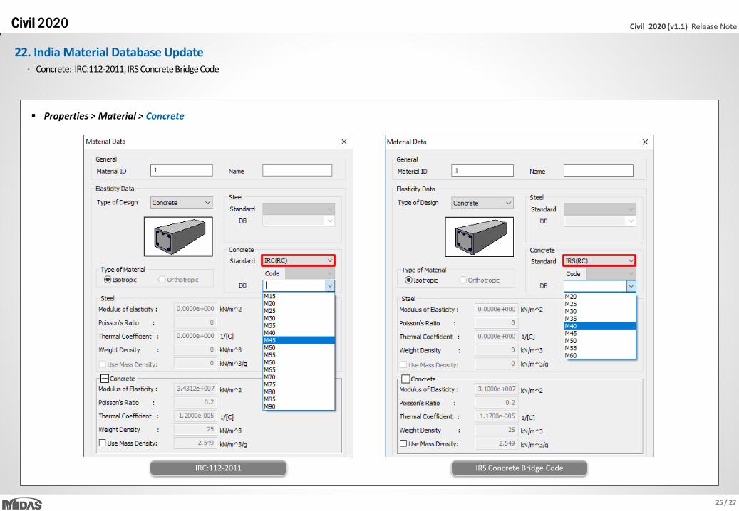
22. India Material Database Update
Properties > Material > Concrete
• Concrete: IRC:112-2011, IRS Concrete Bridge Code
IRC:112-2011 IRS Concrete Bridge Code

26 / 27
Civil 2020 (v1.1) Release Note Civil 2020
23. IRS Load Combination
Results > Load Combination
• Load combination can now be auto-generated based on recommendations in IRS Concrete Bridge Code, including derailment loads
• These load combination could be used for IRS PSC design
Load Combination dialogue box

27 / 27
Civil 2020 (v1.1) Release Note Civil 2020
24. Prestressed Concrete Design by IRS Concrete Bridge Code
PSC > Design Parameter > Parameters > IRS
• Prestressed concrete girder design by IRS Concrete Bridge Code is now available.
Input & Output parameters Excel Report


