Note The terms "Unidirectional Path Switched Ring" and "UPSR" may appear in Cisco literature. These terms do not refer to using Cisco ONS 15xxx products in a unidirectional path switched ring configuration. Rather, these terms, as well as "Path Protected Mesh Network" and "PPMN," refer generally to Cisco's path protection feature, which may be used in any topological network configuration. Cisco does not recommend using its path protection feature in any particular topological network configuration.
Release notes address closed (maintenance) issues, caveats, and new features for the Cisco ONS 15454 SONET multiplexer. For detailed information regarding features, capabilities, hardware, and software introduced with this release, refer to the “Release 7.2” version of the Cisco ONS 15454 DWDM Installation and Operations Guide; and the “Release 7.2” version of the Cisco ONS 15454 Procedure Guide; Cisco ONS 15454 Reference Manual; Cisco ONS 15454 Troubleshooting Guide; and Cisco ONS 15454 SONET TL1 Command Guide. For the most current version of the Release Notes for Cisco ONS 15454 Release 7.2.3, visit the following URL:
Obtaining Documentation and Submitting a Service Request, page 59
Changes to the Release NotesThis section documents supplemental changes that have been added to the Release Notes for Cisco ONS 15454 Release 7.2.3 since the production of the Cisco ONS 15454 System Software CD for Release 7.23.
The following changes have been added to the release notes for Release 7.23:
• The Caveats section has been updated with the following caveats:
– CSCsk03288
– CSCsj43651
– CSCsj43438
– CSCsj41576
– CSCsj39658
– CSCsj32404
– CSCsi97611
– CSCsi91284
– CSCsi63612
– CSCsi74508
– CSCse83671
– CSCsi84335
– CSCsl22337
• The Resolved Caveats for Release 7.2.x section has been updated with the following caveats:
– CSCsj37492
– CSCsj28069
– CSCsj22727
– CSCsj21505
– CSCsj00112
– CSCsi97548
– CSCsi97098
– CSCsi94493
– CSCsi90012
– CSCsi78162
– CSCsi46648
– CSCsi79020
– CSCsi72241
– CSCsc67911
– CSCsi68800
2Release Notes for Cisco ONS 15454 Release 7.2.3
OL-13076-01
Caveats
CaveatsReview the notes listed below before deploying the ONS 15454. Caveats with tracking numbers are known system limitations that are scheduled to be addressed in a subsequent release. Caveats without tracking numbers are provided to point out procedural or situational considerations when deploying the product.
Alarms
CSCsj26750
When the card type in CTC is changed from DS1_14 to DS1_E1_56 with DS1-14 physical card in the slot, the LED in DS1_14 card will show Act (Green) LED, instead of Fail (RED) LED. This issue will be resolved in a future release.
Hardware
CSCsj43651
Occasional hits appear in DS3XM12 traffic during 1:N PG manual switch happens. This issue also occurs when switch happens due to hard reset and or soft reset conditions.
This issue occurs under the following conditions:
• DS3 Payload with DS3 Framing-M13
• DS1 Pay load with Framing-ESF.
Workaround is to either change the DS1 Payload Framing to D4 or keep it unframed.
This issue will be resolved in a future release.
CSCsj43438
Cards do not come up after hard rest and or soft reset when TCC2 is stressed.
This issue will be resolved in a future release.
CSCsj41576
Traffic on DS3E card is interrupted for more than two seconds.
CONTBUS-IO_A or CONTBUS-IO_A alarms appear along with an AutoReset of DS3E card.
This issue occurs when TCC is fully loaded with different scripts running on it. Also, no Protection Group is available for DS3E card. The DS3E traffic interruption happens because the DS3E goes for a watchdog reset due to timing out of socket communication attempts with TCC. Since TCC is unable to service the socket requests from DS3E, the IO card times out after three minutes since the start of socket open attempt, and goes for a watchdog reset.
Workaround:
3Release Notes for Cisco ONS 15454 Release 7.2.3
OL-13076-01
Caveats
When TCC is fully stressed, run the DS3E traffic with a 1:1/1:N Protection Group. This would allow the DS3E to switch to protect card and help the traffic hit being lesser than 50 Millie seconds.
This issue will be resolved in a future release.
CSCsj39658
Sometimes, TCC reboots due to a corruption in the mbuf free lists. This issue happens very rarely. No workaround available. This issue will be resolved in a future release.
CSCsj32404
Fan speed is not properly regulated if the Fan Tray is inserted when the CTX is already up and running.
Workaround is to change the temperature.
This issue will be resolved in a future release.
CSCsi97611
Traffic hits greater than 50 ms may be seen occasionally when traffic is on Protect path and a Force Switch is initiated and cleared. When Force Switch is cleared, hits greater than 50ms are occasionally observed. No workaround available. This issue will be resolved in a future release.
CSCsi91284
AD-4B board reports VOA-HDEG alarm after changing OOS to IS. This issue will be resolved in a future release.
CSCsi63612
Unidirectional DS3 traffic is not happening after upgrading to 7.05. This issue will be resolved in a future release.
CSCsd94528
Intermittent Packet drops can occur when connecting a Catalyst Switch to a CE1000 during autonegotiation.
For more information review the following field notice:
FN - 62423 - 15454-CE-1000-4 Card Gets Burst Data from Incoming Source to FPGA of the CE-1000-4 Card Causing the Upper Layers of the Source to Resend
This issue is resolved in Release 8.0.
CSCed18803
Rarely, the non-enhanced Muxponder unit does not pass Jitter Tolerance test from Trunk port to client port as per ITU-T G.825, 2 Mb/s mask, at the 10 Hz specific setpoint. The Muxponder should be configured with G.709 Off, FEC Off and Trunk signal provided by external Jitter test box, and the unit
client port output monitored for errors, to see this issue. This issue will not be resolved. Note that in normal network configurations the muxponder is operated with G.709 and FEC turned on, and the jitter tolerance tests pass.
CSCuk48503
Under specific conditions the non-enhanced MXPD does not pass the Telcordia GR-253/G.825 Jitter generation mask test on 10G TX Trunk port. The 2.5 G TX Client jitter generation is always within mask and does not exhibit this issue. This occurs only when, in SONET mode, there is no FEC, no G.709, and client interfaces are looped back, with non-synchronous clocking, and the jitter testbox TX connected to Trunk RX port, while the jitter testbox RX is connected to the Trunk TX port. The jitter testbox TX clock recovers from RX with an additional 5 ppm offset added. This issue will not be resolved.
CSCuk44284
An optical connector and optical attenuators inserted into the SFP may force the fiber against the shelf door when it is closed. Use the following types of optical connectors and optical attenuators when connecting to the SFP:
• Optical connectors: The length of the connector (starting from the ferule tip) plus the fiber boot must be 50 mm or shorter.
• Optical Attenuators: The following attenuator Cisco P/Ns are recommended:
– 39-0228-XX
– 39-0229-XX
– 39-0230-XX
Jitter Performance with XC10G
During testing with the XC10G, jitter generation above 0.10 UI p-p related to temperature gradient testing has been observed. This effect is not expected to be seen under standard operating conditions. Changes are being investigated to improve jitter performance in a future release. Tracking numbers related to this issue include CSCdv50357, CSCdv63567, CSCdv68418, CSCdv68441, CSCdv68389, CSCdv59621, and CSCdv73402.
CSCdz49928
When using KLM type fuses with specific types of fuse and alarm panels, the PWR-REDUN alarm may not be displayed once the fuse is blown. A KLM fuse does not have a blown fuse indicator built into it. As a result, the blown fuse detection circuitry on the FAP may continue to provide voltage on its output despite a blown fuse.
Maintenance and Administration
Caution VxWorks is intended for qualified Cisco personnel only. Customer use of VxWorks is not recommended, nor is it supported by Cisco's Technical Assistance Center. Inappropriate use of VxWorks commands can have a negative and service affecting impact on your network. Please consult the troubleshooting guide
5Release Notes for Cisco ONS 15454 Release 7.2.3
OL-13076-01
Caveats
for your release and platform for appropriate troubleshooting procedures. To exit without logging in, enter a Control-D (hold down the Control and D keys at the same time) at the Username prompt. To exit after logging in, type “logout” at the VxWorks shell prompt.
Note CTC does not support adding/creating more than 5 circuits in auto-ranged provisioning. This is as designed.
Note In releases prior to 4.6 you could independently set proxy server gateway settings; however, with Release 4.6.x and forward, this is no longer the case. To retain the integrity of existing network configurations, settings made in a pre-4.6 release are not changed on an upgrade to Release 7.x. Current settings are displayed in CTC (whether they were inherited from an upgrade, or they were set using the current GUI).
CSCsi74508
A Cisco IOS device may produce the following error when reading or writing the configuration:
Error Message %DATACORRUPTION-1-DATAINCONSISTENCY: write of 11 bytes to 10 bytes
No workaround available. This issue will be resolved in a future release.
CSCse83671
In Multishelf configuration, Node Controller (NC) can be changed from Ethernet Switch to Stand Alone with equipped Subtended Shelf Controller (SSC). CTC user is allowed to change the NC from Ethernet Switch mode to Stand Alone. When the NC is up again in Stand Alone mode the SSC shelf is lost. No workaround available. This issue will be resolved in a future release.
CSCsi84335
Tracebacks observed in parseCallerIDString.
No workaround available. This issue will be resolved in a future release.
CSCsh39551
DCC Tunnel Link shows incorrect bandwidth in the circuit wizard manual routing panel when the DCC tunnel is created between two disparate OC/STM cards. This is expected to be resolved in a future release.
CSCsg13470
On the multi shelf with 8 shelf during the SSC SW download. SSC TCC remains hanging. This issue will be resolved in a future release.
6Release Notes for Cisco ONS 15454 Release 7.2.3
OL-13076-01
Caveats
CSCse53347
8.0 SW Activation fails in Multishelf configuration. Activating 8.0 SW release or next releases when previous release is 7.01. Upgrades from 7.01 to 9.0 shall require an intermediate upgrade to 7.04, 7.2, 7.22 or 8.0. Workaround is to extract one of the SSC TCCs and activate. This issue will be resolved in a future release.
CSCse04064
Activate revert with 2 TCC sometimes fails after displaying it succeeded. During SW release Activate/Revert. No workaround available. This issue will be resolved in a future release.
CSCsd91724
MSTP MS SW Activation fails. No internal LAN redundancy and the only Ethernet cable are
connected to Standby TCC of subtended shelf.
Workaround:
Step 1 Connect internal LAN redundancy.
Step 2 Switch Active with Stand-By TCC in Node Controller Shelf
This issue is expected to be resolved in future releases.
CSCse90736
SSC connected via MS-ISC is not discovered by NC. After activation from previous Multishelf releases to 7.02
Workaround:
Step 1 Reset the active NC TCC,
Step 2 Reset both MS-ISC,
Step 3 Reset the TCC2s boards,
Step 4 Reset MS-ISC-100 boards.
This issue will be resolved in a future release.
CSCse98553
The cards plugged in the sub shelves are reported as "not present" even if they are plugged and working. MSTP Multishelf NE. This may occur after a reset of the TCCs of the Node Controller (i.e. during SW activate or DB restore)
Workaround: SW reset the Active TCC of the subtended shelves.
This issue will be resolved in a future release.
7Release Notes for Cisco ONS 15454 Release 7.2.3
OL-13076-01
Caveats
CSCsf09350
The cards plugged in the sub shelves are reported as "not present" even if they are plugged and working. MSTP Multishelf NE. This may occur after a reset of the TCCs of the Node Controller (i.e. during SW activate or DB restore).
Workaround: SW reset the Active TCC of the subtended shelves. This issue will be resolved in a future release.
CSCsf22525
A link fails while connecting an SSC to NC in a multi-shelf environment. Changing the node configuration from single shelf to multi-shelf and assigning the SSC role, the SSC will be able to connect to NC only after 6 minutes. No workaround available. This issue will be resolved in a future release.
CSCse89357
CTC Network view shows up without any Nodes. The initialization of the network view sometimes would get interrupted with exceptions. Workaround is to relaunch CTC. This issue will be resolved in a future release.
CTC Network view shows up without any Nodes. The initialization of the network view sometimes would get interrupted with exceptions. Workaround is to relaunch CTC. This issue will be resolved in a future release.
CSCse96077
On an IO port with this issue false TCAs that indicate line or traffic problems are raised every 15 min. after the 15 min. pm report. There are no alarms with the associated ports. Traffic is not affected. In Release 7.2, during a very short period when the defect is present (less than 1 sec.), false TCAs might be raised. This can be reproduced by either removing or then reinserting the card, or by a small burst of defects.
• DWDM, E1, E1_42, OC3-8, OC12-4, MRC-12, OC192XFP; and ONS 15310-CL and ONS 15310-MA IO ports.
There are two work-arounds:
• Place the affected ports in OOS-DSBLD and then back to IS. This clears the problem for the specific port on the card, but the traffic will be down during the period of OOS-DSBLD.
• Soft reset the card with problem ports. This clears the problem on all ports on the card. Soft reset might cause a protection switch if any circuit path on the card or any port on the card or the card itself is in a protection group. Note that the protection switch itself might cause a defect burst, which might introduce false TCAs. Before resetting the card, check if any circuit, port, or card is in a protection group. If there is Path, BLSR, 1+1 or 1:1/1:N protection on the card, lock the protection using a switch command (for example, LOCKOUT/LOCKON) available to users before you reset the card ensuring that no protection switch occurs during soft reset, and that traffic will not be affected. For a card with no protection type, simply soft reset the card and traffic will not be affected.
This issue will be resolved in a future release.
8Release Notes for Cisco ONS 15454 Release 7.2.3
OL-13076-01
Caveats
CSCsd92505
Traffic hit from 100mS to 300ms might occur during unit SW reset or firmware upgrade.
The problem is present on OPT-PRE and OPT-BST with the vendorID=1025, visible from the Inventory panel of the CTC.
The problem appears under the following conditions:
OPT-PRE
Control Gain: Always OK
Control Power: Hits below -33dBm
OPT-BST
Control Gain: Might have hits for gain > 17 dB and Pin < -10 dBm (3chs @ ~ -14dBm)
Control Power: N/A
No workaround available. This issue is expected to be resolved in 7.01 and above, except 7.2.
CSCsd47626
Bulk deletion of Low Order Server Trails can cause a TCC card to reset. To avoid this delete low order server trails one by one. This issue will be resolved in Release 8.0.
CSCsc00811
Deleting a monitor circuit and its parent at the same time might result in a PARTIAL parent circuit. To avoid this, delete the monitor circuit before deleting the parent circuit. This issue will not be resolved
CSCsc36281
The software Activating progress popup window might fail to automatically close during multiple or parallel software activations. If this occurs you must manually close the popup window. The following error message might also be raised and need to be closed:
“EID-3251 Unable to complete requested action. Unable to activate because the working software version is newer than the protect one.”
To ensure that all nodes are using the correct software version you should close and restart CTC. This issue will be resolved in a future release.
Mismatch Equipment Attributes Alarm on EIA
In Release 6.0 a Mismatch Equipment Attributes (MEA) alarm is raised incorrectly against the B-Side BIC (EIA) on an ONS 15454 node using the 15454-SA-HD (high density) chassis with 1BNCB48, 1BNCB24, or 1SMBB84 EIAs installed. The 1BNCB48, 1BNCB24, and 1SMBB84 EIA panels are compatible with the 15454-SA-HD shelf assembly; however, the software in Release 6.0 fails to recognize their compatibility. The MEA alarm raised as a result of this issue is not service impacting, but does cause a standing alarm.
As a workaround to the standing alarm, you can change the BIC-MEA alarm severity by creating and using a custom alarm profile following the steps that apply for your network in the NTP-A71 Create, Download, and Assign Alarm Severity Profiles procedure of the Manage Alarms chapter in the Cisco ONS 15454 Procedure Guide, Release 6.0. This issue will be resolved in Release 6.1.
9Release Notes for Cisco ONS 15454 Release 7.2.3
OL-13076-01
Caveats
CSCeh84908
A CTC client session can disconnect from an ONS node during simultaneous deletion of large numbers of VT level circuits (3000+). Connectivity to the node will recover without any user action. If the condition persists, restart the CTC session to reconnect. This issue is under investigation.
CSCei36415
When retrieving GBIC inventory for the FC_MR-4, nothing is returned for the CLEI code. In a future release, enhanced inventory information will be available for ONS GBICs. This will include the CLEI code.
CSCeh92201
When you create a bidirectional BLSR-Path Protection IDRI circuit using auto-routing and select the PCA option for secondary spans, the circuit is created over working BLSR spans and does not use PCA spans. To enforce the use of the PCA option, provision the circuit using manual routing. This issue will not be resolved.
CSCee96164
The Wait To Restore (WTR) alarm does not appear to be raised for as long as the WTR timer is set for. The WTR is raised correctly, but the alarm is hidden for the first 12 seconds due to the clear soaking time for a CLDRESTART alarm. You can see this behavior if you set up a 1+1 bidirectional revertive protection group, remove the working card, and then reinsert the card. There are no plans to change this behavior.
CSCee25136
If you create a PM schedule with the Start time for the PM report equal to 00:00 (in TL1, “0-0”), after a few minutes the PM report start time might change to 23:59 (in TL1, “23-59”). This issue will not be resolved.
CSCed23484
A user might remain in the logged-in state after rebooting the PC while logged into a node running CTC. The user login will time out once the “Idle User Timeout” limit is up. Alternatively, you can log in as a superuser and force the user off. This issue will not be resolved.
CSCds88976
When a new circuit is created around a ring (Path Protection or BLSR), the SD BER or SF BER alarm can be raised depending on the order in which the spans are provisioned. The alarms will eventually clear by themselves. Traffic is not affected. This issue will not be resolved.
10Release Notes for Cisco ONS 15454 Release 7.2.3
OL-13076-01
Caveats
CSCdu82934
When you auto-route a VT circuit on an ONS 15454 node, a path is computed based on the availability of STSs on the nodes involved. This selection process, when combined with a lack of VT matrix (or STS-VT connections) on an auto-route selected node, can result in the VT circuit creation failing with the message “unable to create connection object at node.” To correct this situation, manually route VT circuits in cases when auto-routing fails. The error message will indicate which node is at issue.
CSCef28522
When you inject errors on a splitter protection card in the node's working port, CVL and ESL are incremented for the working and protect far end ports. This issue will not be resolved.
CSCuk49106
The amplifier gain set point shown by CTC and the actual measured amplifier gain differ. The following steps illustrate this issue.
Step 1 Reduce the insertion loss of the span just before the amplifier.
Step 2 Execute the APC procedure.
The APC procedure does not check consistency between the gain set point and the real gain, but rather only verifies the amplifier total output power. As a workaround, manual setting can be performed to align these values, although the discrepancy does not impact the normal functioning of the amplifier. This issue will not be resolved.
CSCef05162
Clearing the displayed statistics for a port will also clear the displayed history for that port. Clearing the displayed statistics for all ports will also clear the displayed history for all ports. There is no warning message from the TCC2. If History information is to be retained, do not clear displayed statistics for any port without first documenting the displayed history information for the associated port. This issue will not be resolved.
CSCef29516
The ALS pulse recovery minimum value is 60 instead of 100. If this occurs, increase the value to 100. This issue will not be resolved.
CSCeb36749
In a Y-Cable configuration, if you remove the client standby RX fiber; a non-service affecting LOS is raised, as expected. However, if you then remove the trunk active RX fiber; a non-service affecting LOS-P is raised, but the previously non-service affecting LOS on the client port is now escalated to a service affecting alarm, in spite of no traffic having been affected. This issue will not be resolved.
11Release Notes for Cisco ONS 15454 Release 7.2.3
OL-13076-01
Caveats
CSCee82052
After setting the node time (either manually or via NTP) you must wait for the endpoint of the interval to be reached before the end time will reflect the recently-set node time. Until this has occurred, the date time stamp for the end of the retrieved interval remains 12/31/69. This issue has been closed and will not be resolved.
CSCdx35561
CTC is unable to communicate with an ONS 15454 that is connected via an Ethernet craft port. CTC does, however, communicate over an SDCC link with an ONS 15454 that is Ethernet connected, yielding a slow connection. This situation occurs when multiple ONS 15454s are on a single Ethernet segment and the nodes have different values for any of the following features:
• Enable OSPF on the LAN
• Enable Firewall
• Craft Access Only
When any of these features are enabled, the proxy ARP service on the node is also disabled. The ONS 15454 proxy ARP service assumes that all nodes are participating in the service.
This situation can also occur immediately after the aforementioned features are enabled. Other hosts on the Ethernet segment (for example, the subnet router) may retain incorrect ARP settings for the ONS 15454s.
To avoid this issue, all nodes on the same Ethernet segment must have the same values for Enable OSPF on the LAN, Enable Firewall, and Craft Access Only. If any of these values have changed recently, it may be necessary to allow connected hosts (such as the subnet router) to expire their ARP entries.
You can avoid waiting for the ARP entries to expire on their own by removing the SDCC links from the affected ONS 15454 nodes. This will disconnect them for the purposes of the proxy ARP service and the nodes should become directly accessible over the Ethernet. Network settings on the nodes can then be provisioned as desired, after which the SDCC can be restored.
This issue will not be resolved.
CSCdy56693
Microsoft Windows XP uses more memory than previous Microsoft operating systems, and this may result in reduced CTC performance. To avoid reduced performance, you can:
• Limit the number of nodes you log into
• Avoid or limit bulk operations
• Avoid bulk circuit deletion
• Prevent CTC’s discovery of DCC connected nodes by using the login “Disable Network Discovery” feature
• Prevent CTC’s discovery of circuits unless needed by using the login “Disable Circuit Management”
CSCdy62092
When a node connected via SDCC has no Ethernet LAN connectivity, display of SDCC termination alarms is delayed if the fiber connecting a DCC connected node is removed. This issue cannot be resolved.
12Release Notes for Cisco ONS 15454 Release 7.2.3
OL-13076-01
Caveats
CSCdy10030
CVs are not positively adjusted after exiting a UAS state. When a transition has been made from counting UAS, at least 10 seconds of non-SES must be counted to exit UAS. When this event occurs, Telcordia GR-253 specifies that CVs that occurred during this time be counted, but they are not. There are no plans to resolve this issue at this time.
CSCdy11012
When the topology host is connected to multiple OSPF areas, but CTC is launched on a node that is connected to fewer areas, the topology host appears in CTC, and all nodes appear in the network view, but some nodes remain disconnected. This can occur when the CTC host does not have routing information to connect to the disconnected nodes. (This can happen, for example, if automatic host detection was used to connect the CTC workstation to the initial node.)
CTC will be able to contact the topology host to learn about all the nodes in all the OSPF areas, but will be unable to contact any nodes that are not in the OSPF areas used by the launch node. Therefore, some nodes will remain disconnected in the CTC network view.
To work around this issue, if no firewall enabled, then the network configuration of the CTC host can be changed to allow CTC to see all nodes in the network. The launch node must be on its own subnet to prevent network partitioning, and craft access must not be enabled. The CTC host must be provisioned with an address on the same subnet as the initial node (but this address must not conflict with any other node in the network), and with the default gateway of the initial node. CTC will now be able to contact all nodes in the network.
If a firewall is enabled on any node in the network, then CTC will be unable to contact nodes outside of the initial OSPF areas. This issue will not be resolved.
NE Defaults
The following caveats apply for NE defaults when managing older, pre-Release 4.5 nodes.
• OC12-4 allows provisioning of PJStsMon from 0 to 48. The workaround is to limit provisioning to between Off and 1 to 12 only.
• CTC displays “PJStsMon=off” in the standard provisioning pane when provisioning PJStsMon off; however, TL1 and the NE Defaults editor both display 0 for this same condition.
• If you only make changes to a single default in the NE defaults editor, you must click on another default or column before the Apply button becomes functional.
ONS 15454 Conducted Emissions Kit
If you are deploying the Cisco ONS 15454 within a European Union country that requires compliance with the EN300-386-TC requirements for Conducted Emissions, you must obtain and install the Cisco ONS 15454 Conducted Emissions kit (15454-EMEA-KIT) in order to comply with this standard.
CSCdv10824: Netscape Plugins Directory
If you use CTC, JRE, and the Netscape browser with a Microsoft Windows platform, you must ensure that any new installation of Netscape uses the same Netscape directory as the previous installation did, if such an installation existed. If you install Netscape using a different path for the plugins directory, you will need to reinstall JRE so that it can detect the new directory.
13Release Notes for Cisco ONS 15454 Release 7.2.3
OL-13076-01
Caveats
“Are you sure” Prompts
Whenever a proposed change occurs, the “Are you sure” dialog box appears to warn the user that the action can change existing provisioning states or can cause traffic disruptions.
Common Control Cards
CSCse32518I
TCCs intermittently restart. Noise or communication problem in the TCC to fan tray communication channel that occurs during normal operation causes TCC card to reset. Workaround is to replace fan tray. This issue will be resolved in a future release.
CSCsh28828
• Pull out the standby TCC.
• IMPROPRMVL is raised on slot 11 and PROTNA is raised on slot 7.
• Soft reset the active TCC on slot 7.
• IMPROPRMVL clears when the TCC reboots.
• Soft reset of the active TCC should not edit a provisioning database.
This issue will be resolved in a future release.
CSCsg40898
SHELF-COMM-FAIL after upgrade to 8.0 and TCC SW reset. Multi-shelf in secure mode from 7.2 to 8.0 releases. Activation is successful. SW reset SSC active TCC. Wait to complete reboot. SW reset NC active TCC. The SSC is lost, SHELF-COMM-FAIL raises. No workaround available. This issue will be resolved in a future release.
CSCdw27380
Performing cross connect card switches repeatedly might cause a signal degrade condition on the lines or paths that can trigger switching on these lines or paths. If you must perform repeated cross connect card switches, lock out the corresponding span (Path Protection, BLSR, or 1+1) first. This issue will not be resolved.
CSCsd88118
MSTP MS in secure mode. SSC duplicate alarm and loss of SSC. Connecting any host with the same IP address of the internal shelf subnet (192.168.190.0).
Work-around: Disconnect the host and SW reset of the NC active TCC. This issue will be resolved in a future release.
14Release Notes for Cisco ONS 15454 Release 7.2.3
OL-13076-01
Caveats
CSCse02598
Multishelf, MSTP. The FDI/PMI is cleared and the alarms which were suppressed by NLAC are instead raised back as alarms. SW Reset the active TCC of the Node Controller. No work-around available. This issue will be resolved in a future release.
CSCse31217
The Standby TCC continuously reboots. MSTP Multishelf NE. Change any sub shelf to stand alone shelf via LCD.
Work-around: Unplug the standby TCC before changing multi-shelf role. After the active TCC has come back as stand alone (at least 2 min.) re-plug the second TCC.
This issue is expected to be resolved in future releases.
CSCse77589
SSC connectivity lost after removing the LAN cable from TCC2P LAN port. Remove the LAN cable from LAN port. It is expected SSC to be reachable via routing with TCC on slot 11 (standby). A COMM-SHELF alarm is reported from CTC and the connectivity to the SSC is lost (i.e. all the boards are greyed out). No workaround available. This issue will be resolved in a future release.
CSCsg27342
When a Multishelf MSTP NE master node is reset for any reason for ex: DB restore, SW activate, SW reset, the Ethernet front port on the TCC has the LEDs turned off (no activity no link). When this happens one workaround is to soft reset the TCC suffering the fault. This issue is resolved in 7.22, 7.04 and 8.0
CSCsg32221
The subtended shelf is disconnected and a SHELF-COMM-FAIL alarm is correctly reported. Multishelf MSTP NE after a reload of the TCC of the Node Controller for any reason (DB restore, SW activate). No workaround available. This issue will be resolved in a future release.
CSCsb62127
A DCC Link discovered by CTC, can show incorrect bandwidth. When a DCC tunnel is created using two different OC cards, like OC12 and OC48 at its ends, CTC Network view shows incorrect bandwidth. Such a provisioning is a provisioning mistake. No workaround available. This issue will be resolved in a future release.
Active Cross Connect (XC10G/XCVT) or TCC2/TCC2P Card Removal
You must perform a lockout in BLSR, Path Protection, and 1+1 before physically removing an active cross connect (XC10G/XCVT) or TCC2/TCC2P card. The following rules apply.
Active cross connect (XC10G/XCVT) cards should not generally be physically removed. If the active cross connect or TCC2/TCC2P card must be removed, you can first perform an XCVT/XC10G side switch or TCC2/TCC2P reset and then remove the card once it is in standby, or you can perform a lockout
15Release Notes for Cisco ONS 15454 Release 7.2.3
OL-13076-01
Caveats
on all circuits that originate from the node whose active cross connect or active TCC2/TCC2P will be removed (performing a lockout on all spans will also accomplish the same goal). No lockout is necessary for switches initiated through CTC or through TL1.
Caution If you mistakenly remove an active TCC2/TCC2P card and you subsequently lose traffic on some interface cards, you may need to physically reset these cards if they fail to regain traffic.
Ethernet Polarity Detection
The TCC2/TCC2P does not support Ethernet polarity detection. The TCC+ and TCCI both support this feature. If your Ethernet connection has the incorrect polarity (this can only occur with cables that have the receive wire pairs flipped), the TCC+/I will work, but the TCC2/TCC2P will not. In this event, a standing condition, “LAN Connection Polarity Reverse Detected” (COND-LAN-POL-REV), will be raised (a notification will appear on the LCD, and there will be an alarm raised). This issue will most likely be seen during an upgrade or initial node deployment. To correct the situation, ensure that your Ethernet cable has the correct mapping of the wire wrap pins. For Ethernet pin mappings, consult the user documentation.
Optical IO Cards
CSCsk03288
The OC48-LR-1550-1 optical card with P/N 87-32-00001 and firmware (bootrom) rev number 76-99-00014-x02a continuously reboots and does not start up during upgrade to a software release 7.20 through 7.23 or 8.0.
Before upgrading to releases 7.20, 7.21, 7.22, 7.23 or 8.0, it is recommended to retrieve the inventory list through CTC or TL1 and check the HW part number field for 87-32-00001 and firmware rev field for 76-99-00014-x02a. If any card matches the HW part number and firmware rev number, replace it with the newer version of the OC48 card such as the OC48AS or MRC card.
This issue will be resolved in Release 8.5.
CSCei26718
On the 15454_MRC-12, when a one way VT/VC circuit on Path Protection over 1+1 protection is
created, the alarm behavior is not the same as in two way circuit creation. In particular, for the one way circuit creation, UNEQ-V and PLM-V alarms are reported, and the circuit state remains OOS. This issue will not be resolved.
CSCdw66444
When an SDH signal is sent into an ONS 15454 OC-12/STM-4 (IR, 1310 LR and 1550 LR) or an OC-48/STM-16 high-speed (IR and LR) port which has been configured to support SDH, an SD-P (Signal Degrade) alarm will appear as soon as the circuit is created. This alarm will continue to exist until the circuit is deleted.
16Release Notes for Cisco ONS 15454 Release 7.2.3
OL-13076-01
Caveats
To avoid this problem, when provisioning an OC-12/STM-4 (IR, 1310 LR and 1550 LR) or an OC-48/STM-16 high-speed (IR and LR) port to support SDH, disable the signal degrade alarm at the path level (SD-P) on the port.
Also, PM data at the path level will not be reliable. You must set associated threshold values to 0 in order to avoid threshold crossing alerts (TCA) on that port. The path threshold values to set to zero are CV-P, ES-P, SES-P, and UAS-P.
These issues are the result of a hardware limitation, and there are no current plans to resolve them.
CSCdw09604
If you are using an XC10G with OC-48, you must use either OC-48AS or OC-48 cards with a revision number higher than 005D.
Electrical IO Cards
CSCse96077
On an IO port false TCAs that indicate line or traffic problems might be raised every 15 min. after the 15 min. pm report. There are no alarms with the associated ports. Traffic is not affected.
In Release 7.2, during a very short period when the defect is present (less than 1 sec.), false TCAs might be raised. This can be reproduced by either removing and then reinserting the card, or by a small burst of defects.
The cards affected are: ONS 15454 DS1, DS1_E1_56, DS3 (including DS3, DS3N, DS3E, DS3NE), DS3_EC1, DS3XM, DWDM, E1, E1_42, OC3-8, OC12-4, MRC-12, OC192XFP; and ONS 15310-CL and ONS 15310-MA IO ports.
There are two work-arounds:
1. Place the affected ports in OOS-DSBLD and then back to IS. This clears the problem for the specific port on the card, but the traffic will be down during the period of OOS-DSBLD.
2. Soft reset the card with problem ports. This clears the problem on all ports on the card.
Soft reset might cause a protection switch if any circuit path on the card, or any port on the card or the card itself is in a protection group. Note that the protection switch itself might cause a defect burst, which might introduce false TCAs. Before resetting the card, check if any circuit, port, or card is in a protection group. If there is Path, BLSR, 1+1 or 1:1/1:N protection on the card, lock the protection using a switch command (for example, LOCKOUT/LOCKON) available to users before you reset the card ensuring that no protection switch occurs during soft reset, and that traffic will not be affected. For a card with no protection type, simply soft reset the card and traffic will not be affected.
This issue will be resolved in a future release.
CSCsc65320 and CSCin92295
In a DS3-EC1-48 1:N protection group for which a Path Protection circuit drops onto a 1:N protected card, if you remove the card and then reseat it the switch time might exceed 60 ms. This issue will be resolved in a future release.
17Release Notes for Cisco ONS 15454 Release 7.2.3
OL-13076-01
Caveats
CSCsc60437
DS3XM one way circuits created with no electrical lines attached to the ports fail to carry traffic. This issue will be resolved in Release 8.0.
CSCei59527
When an XC switch occurs, LOF is driven to the line side. On a DS1-14 this can cause us to see long switch times that are related to hardware issues if the “Treat LOF as a Defect” flag has been set. To avoid this issue, do not set the “Treat LOF as a Defect” flag to true on DS1-14 cards. A future release will remove the “Treat LOF as a Defect” option for this card.
CSCeh43011
An LOS alarm is cleared when switching to protect when the working card is on opposite side of the shelf from the protect card (in portless configuration) in a DS3XM-12 1:N protection group. An electrical port brought into IS state on the portless only card produces an LOS alarm. If you then switch to protect, the alarm appears to clear. To avoid this issue, do not bring electrical ports into IS state on a portless only card. This issue will be resolved in a future release.
CSCdx40300
A transient WKSWPR condition is raised upon deletion of a DS3XM 1:1 protection group. This issue will be resolved in a future release.
CSCec39567
Deleting a DS3I 1:N protection group may leave the protect card LED in a standby state. This can occur in a DS3I 1:N protection group with a LOCKON applied to the working card (ONS 15454 ANSI chassis only). Upon deleting the protection group, the LED on the protect DS3I card and the CTC display are still in the standby state. Soft reset the protect card to update the LED on the card and in CTC. An alternative workaround is to remove the LOCKON before deleting the protection group. This issue will be resolved in a future release.
Data IO Cards
SONET and SDH Card Compatibility
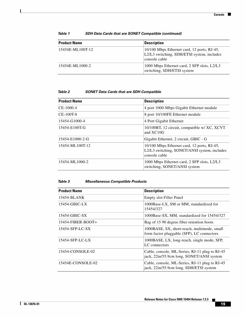
Tables 1, 2, and 3 list the cards that are compatible for the ONS 15454 SONET and ONS 15454 SDH platforms. All other cards are platform specific.
Table 1 SDH Data Cards that are SONET Compatible
Product Name Description
15454E-G1000-4 4 port Gigabit Ethernet Module - need GBICs
15454E-E100T-12 12 port 10/100BT Ethernet Module
15454E-E1000-2 2 port Gigabit Ethernet Module - need GBICs
15454-GBIC-LX 1000Base-LX, SM or MM, standardized for 15454/327
15454-GBIC-SX 1000Base-SX, MM, standardized for 15454/327
15454-FIBER-BOOT= Bag of 15 90 degree fiber retention boots
15454-SFP-LC-SX 1000BASE, SX, short-reach, multimode, small form factor pluggable (SFP), LC connectors
15454-SFP-LC-LX 1000BASE, LX, long-reach, single mode, SFP, LC connectors
15454-CONSOLE-02 Cable, console, ML-Series, RJ-11 plug to RJ-45 jack, 22in/55.9cm long, SONET/ANSI system
15454E-CONSOLE-02 Cable, console, ML-Series, RJ-11 plug to RJ-45 jack, 22in/55.9cm long, SDH/ETSI system
Table 1 SDH Data Cards that are SONET Compatible (continued)
Product Name Description
19Release Notes for Cisco ONS 15454 Release 7.2.3
OL-13076-01
Caveats
CSCsc11981
Under certain circumstances, E-series cards might learn invalid MAC addresses and temporarily lose well-known/static addresses, possibly resulting in high flood rates. This issue can occur when traffic flows through an E-series card and there are no MAC addresses currently in the MAC table for that E-series card (for instance, after you have cleared the complete MAC table, or when the node is just coming up). The chipset can cause the E-series card to learn invalid addresses in this scenario under high rates of flood traffic (multicast, broadcast, unknown) or PHY interface noise. Side-effects of clearing the MAC table when traffic is flowing can cause the E-series card to lose well-known/static MAC addresses along with dynamically learned MAC addresses. This can cause high flood rates (multicast, broadcast, unknown) possibly reaching the limitation described in the following field notice:
http://www.cisco.com/en/US/ts/fn/620/fn62423.html
This issue can last for a few seconds (typically less). The workaround is to avoid issuing any operation (such as the “Clear all MAC” command) that clears the complete MAC table under heavy traffic loads. To recover from this issue, wait for a few seconds to let the invalid addresses age out, and to allow the software to restore the well-known/static MAC addresses.
CSCdy37198
On Cisco ONS 15454s equipped with XCVT cross-connect cards, neither the E100T-12 nor the E1000-2 cards raise an alarm or condition in CTC when Ethernet traffic is predictably lost due to the following circumstances:
Circuits exist between Ethernet cards (E100T-12 and/or E1000-2) built over Protection Channel Access (PCA) bandwidth on BLSR spans. When BLSR issues a switch, the PCA bandwidth is preempted. Since there is no longer a connection between the ends of the Ethernet circuit, traffic is lost.
Note In nodes equipped with XC10G, these Ethernet cards will raise an AIS-P condition.
This issue will not be resolved.
CSCdr94172
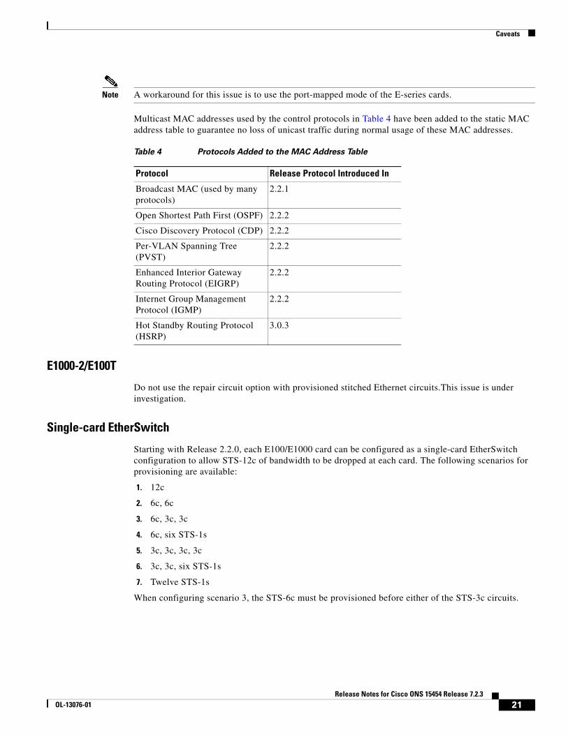
Multicast traffic can cause minimal packet loss on the E1000-2, E100-12, and E100-4 cards. Packet loss due to normal multicast control traffic should be less than 1%. This issue was resolved in Release 2.2.1 for broadcast, and in Release 2.2.2 for OSPF, and some multicast frames. As of Release 3.0.3, the ONS 15454 supports HSRP, CDP, IGMP, PVST, and EIGRP, along with the previously supported broadcast and OSPF.
Note If multicast is used for such applications as video distribution, significant loss of unicast and multicast traffic will result. These cards were not designed for, and therefore should not be used for, such applications.
Note If the multicast and flood traffic is very rare and low-rate, as occurs in most networks due to certain control protocols and occasional learning of new MAC addresses, the loss of unicast frames will be rare and likely unnoticeable.
Note A workaround for this issue is to use the port-mapped mode of the E-series cards.
Multicast MAC addresses used by the control protocols in Table 4 have been added to the static MAC address table to guarantee no loss of unicast traffic during normal usage of these MAC addresses.
E1000-2/E100T
Do not use the repair circuit option with provisioned stitched Ethernet circuits.This issue is under investigation.
Single-card EtherSwitch
Starting with Release 2.2.0, each E100/E1000 card can be configured as a single-card EtherSwitch configuration to allow STS-12c of bandwidth to be dropped at each card. The following scenarios for provisioning are available:
1. 12c
2. 6c, 6c
3. 6c, 3c, 3c
4. 6c, six STS-1s
5. 3c, 3c, 3c, 3c
6. 3c, 3c, six STS-1s
7. Twelve STS-1s
When configuring scenario 3, the STS-6c must be provisioned before either of the STS-3c circuits.
When deleting and recreating Ethernet circuits that have different sizes, you must delete all STS circuits provisioned to the EtherSwitch before you create the new circuit scenario. (See the preceding “Single-card EtherSwitch” section for details on the proper order of circuit creation.) Enable front ports so that the VLANs for the ports are carried by the largest circuit first. A safe approach is to enable the front port before you create any circuits and then retain the front port VLAN assignment afterwards. If you break the rules when creating a circuit, or if you have to delete circuits and recreate them again, delete all circuits and start over with the largest first.
CSCds02031 E1000-2/E100
When you drop two 3c multicard EtherSwitch circuits onto an Ethernet card and delete only the first circuit, you should not provision STS-1 circuits to the card without first deleting the remaining STS-3c circuit. If you attempt to create an STS-1 circuit after deleting the first STS-3c circuit, the STS-1 circuit will not work and no alarms will indicate this condition. Under rare conditions, this could trigger a TCC reset. To avoid a failed STS-1 circuit and other possible problems, delete the second STS-3c prior to creating any STS-1 circuit.
CSCed96068
If an ML-Series card running Software Release 4.6.2 or later is interoperating with an ML-Series card running Software Release 4.6.0 or 4.6.1, then the pos vcat resequence disable command must be added to the configuration of the ML-Series card running R4.6.2 or later. For documentation of this command, consult the Ethernet Card Software Feature and Configuration Guide.
CSCec52443
On an ML-series RPR ring circuit deletion or creation causes an approximately 200 ms traffic loss. To avoid this issue, from the ML-series CLI, perform a “shutdown” on both ends of the circuit prior to circuit changes. This issue will not be resolved.
CSCec52372
You must issue a “shut” command to both ends of a POS circuit before placing the circuit OOS, and issue IS before a “no shut” command. Placing a POS circuit OOS without shutting down can cause long traffic hits. This issue will not be resolved.
CSCec51252
You must issue a “shut” on both ends of affected POS circuits before performing a maintenance action on those circuits. If a POS circuit is restored without first issuing the shut commands, one end of the circuits could come up before the other. During that time, traffic is lost because the other end is not up yet. This issue will not be resolved.
CSCea46580
SPR input counters do not increment on a BVI with an SPR interface. This issue will not be resolved.
22Release Notes for Cisco ONS 15454 Release 7.2.3
OL-13076-01
Caveats
CSCea35971
A monitor command may disappear from the configuration after a TCC reboots. To avoid this issue, use the exec command, “terminal monitor,” instead (a minor drawback is that this command applies to all VTYs), or, alternatively, reapply the monitor command after connection is lost. This is as designed.
CSCdz49700
The ML-series cards always forward Dynamic Trunking Protocol (DTP) packets between connected devices. If DTP is enabled on connected devices (which might be the default), DTP might negotiate parameters, such as ISL, that are not supported by the ML-series cards. All packets on a link negotiated to use ISL are always counted as multicast packets by the ML-series card, and STP and CDP packets are bridged between connected devices using ISL without being processed. To avoid this issue, disable DTP and ISL on connected devices. This functionality is as designed.
CSCdz68649
Under certain conditions, the flow-control status may indicate that flow control is functioning, when it is not. Flow-control on the ML-series cards only functions when a port-level policer is configured. A port-level policer is a policer on the default and only class of an input policy-map. Flow-control also only functions to limit the source rate to the configured policer discard rate, it does not prevent packet discards due to output queue congestion.
Therefore, if a port-level policer is not configured, or if output queue congestion is occurring, policing does not function. However, it might still mistakenly display as enabled under these conditions. To avoid this issue, configure a port-level policer and prevent output queue congestion. This issue will not be resolved.
CSCdz69700
Issuing a shutdown/no shutdown command sequence on an ML1000 port clears the counters. This is a normal part of the startup process and there are no plans to change this functionality.
CSCin29274
When configuring the same static route over two or more interfaces, use the following command:
ip route a-prefix a-networkmask a.b.c.d
Where a.b.c.d is the address of the outgoing gateway, or, similarly, use the command:
ip route vrf vrf-name
Do not try to configure this type of static route using only the interface instead of the address of the outgoing gateway. This issue will not be resolved.
CSCin32057
If no BGP session comes up when VRF is configured and all interfaces have VRF enabled ensure that at least one IP interface (without VRF) is configured and add an IP loopback interface on each node. This issue will not be resolved.
23Release Notes for Cisco ONS 15454 Release 7.2.3
OL-13076-01
Caveats
CSCdy47284
ML-100 FastEthernet MTU is not enforced. However, frames larger than 9050 bytes may be discarded and cause Rx and Tx errors. This issue will not be resolved.
CSCdz74432
Issuing a “clear IP route *” command can result in high CPU utilization, causing other processes to be delayed in their execution. To avoid this issue do not clear a large number of route table entries at once, or, if you must use the “clear IP route *” command, do not install more than 5000 EIGRP network routes.
DWDM Cards
CSCsd92505
Traffic hits of 100 ms to 300 ms might occur during an OPT-PRE or OPT-BST card software reset or firmware upgrade. This occurs only with cards displaying the vendor ID 1025 in the CTC node level inventory tab when the following conditions are present for the affected card.
• OPT-PRE
– WorkingMode is set to Output Power and the Input Com Power value is less than -33dBm.
• OPT-BST
– WorkingMode is set to Gain with a Gain value of greater than 17 dB, and Input Com Power is less than -10 dBm (three channels at approximately -14 dBm).
This issue is resolved in Release 7.0.1 and all subsequent releases except for Release 7.2.
CSCeh22604
When an MXP_MR_2.5G card is in MIXED or ESCON mode, TCA and alarm optical thresholds of Tx power for laser bias are configurable for ESCON payload, though not supported. This issue will be resolved in the future release.
CSCei19148
When a port is placed in-service while the conditions necessary to squelch the port are present, as in when the trunk port on a DWDM card is OOS,DSBLD and a client port is placed in-service, the client will momentarily enable, emitting light, before squelching due to the trunk OOS,DSBLD condition. The pulse is approximately 500 ms. This issue will not be resolved.
CSCei87554
When using a 1GE payload over the TXP_MR_2.5G the IfInErrors counter does not report oversized, undersized, or CRC errored frames, but rather, reports frame coding only. This issue will not be resolved.
24Release Notes for Cisco ONS 15454 Release 7.2.3
OL-13076-01
Caveats
CSCsb47323
For MXP_MR_10DME-C and MXP_MR_10DME-L cards, an unexpected RFI condition might be raised along with an OTUk-BDI. When there is an LOS downstream, the node receives OTUk-BDI. Because of the placement of dual OTN and SONET wrappers, it can also receive an RFI. This issue will not be resolved.
CSCsb79548
A long traffic hit can occur when an active TCC2/TCC2P resets while an MXP_MR_10DME-C or MXP_MR_10DME-L card is rebooting.
This issue can be reproduced as follows:
Step 1 1. Set up two MXP_MR_10DME-C or MXP_MR_10DME-L cards, connected back-to-back in two different nodes, A and B.
Step 2 2. Ensure that Node A has two TCC2 cards; one is active, and the other is standby.
Step 3 3. Set up any kind of traffic between the two MXP_MR_10DME-C or MXP_MR_10DME-L cards.
Step 4 4. Soft reset the MXP_MR_10DME card in Node A, then soft reset the active TCC2/TCC2P.
OTUk/ODUk-SD, FEC Uncorrected word alarms are raised on the trunk port. Traffic goes down and does not recover until the MXP_MR_10DME card is able to come up. It is not known when or if this issue will be resolved.
CSCsb94736
After a fault condition (trunk LOS or Y-cable switch) an MXP_MR_10DME card might fail to detect the login message and traffic might not start for some minutes (after multiple login trials). This can occur in an N-F configuration with MDS switch and MXP_MR_10DME distance extension on, where test equipment traffic is set to 2G Fibre channel (FC) full bandwidth occupancy and started. Stop traffic or keep bandwidth occupancy below 80% during the login phase to work around this issue. This issue will not be resolved.
CSCsb95918
All GFP related alarms are raised with their active severities on the standby card after a Y-Cable protection switch. When a DWDM card (with GFP support) in a Y-Cable protection group becomes standby as a result of a Y-Cable protection switch, the GFP alarms raised when the card was active retain their severities instead of assuming standby severities. The alarms can be seen in the alarm pane if not suppressed, or in the condition pane if suppressed. This issue will be resolved in a future release.
CSCsc36494
Manual Y cable switches with squelching turned off can cause a Fibre channel link with brocade switches to go down.
This issue can be reproduced as follows:
25Release Notes for Cisco ONS 15454 Release 7.2.3
OL-13076-01
Caveats
Step 1 Set up MXP_MR_10DME cards so that they are Y cable protected. Squelching is provisioned to be off. Distance extension is turned on.
Step 2 The path between the working pair of Y cable protected cards, has no distance introduced. But the protect path has a delay of 800 km introduced.
Step 3 Start Fibre channel traffic with brocade switches.
Step 4 Perform user-initiated manual Y cable switches from CTC.
After a few switchovers, the FC link will go down. SIGLOSS and GFP-CSF alarms are seen on the CTC.
Cisco recommends you provision squelching to be on when interworking with brocade switches. If for some reason, squelching must be off with brocade switches, Cisco recommends you use a FORCE command to perform Y cable switches. It is not known when or if this issue will be resolved.
CSCsc60472
CTC is not able to discover a TL1 OCHCC circuit provisioned over an ITU-T line card (ITU-T OC48/STM16 and ITU-T OC192/STM64). This issue can occur when, using the TL1 client interface, you create the OCHNC layer that will be used by the OCHCC circuit, then create the OCHCC connections that involve the ITU-T line cards. The result is an OCHNC and two OCHCC partial circuits, instead of an OCHNC and a single OCHCC complete circuit. This issue will not be resolved.
CSCsc14290
LOW communication between two nodes equipped with TXP-MR-10E and AIC-I cards does not work with TXP-MR-10E cards in line termination mode, G.709 enabled, GCC present on the trunk port, and LOW circuits created between the transponders and AIC-I; Cisco recommends that you use EOW instead. This issue will be resolved in a future release.
CSCsc58941
Trunk ports of the TXPP_MR_2.5G and MXPP_MR_2.5G can be in facility and terminal loopback at the same time. this can occur if you provision terminal loopback on the protected trunk port after putting the trunk ports in facility loopback. You can clear this condition by removing loopback provisioning on the trunk ports. This issue will be resolved in a future release.
CSCeh94567
Setting a Terminal loopback on an MXP-2.5G-10G trunk port causes OTUK alarms.
This can occur under the following conditions.
1. Two MXP-2.5G-10G cards are connected via the trunk ports.
2. The client ports are connected to respective STM16 line cards.
3. SDCC is enabled on the client ports and the line cards' STM16 port.
4. A terminal loopback is set on the MXP-2.5G-10G trunk port.
This terminal loopback causes OTUK-LOF and OTUK-IA alarms to be reported on both MXP-2.5G-10G trunk ports. This issue will not be resolved.
26Release Notes for Cisco ONS 15454 Release 7.2.3
OL-13076-01
Caveats
CSCef15415
RMON TCAs are not raised on the TXPP_MR_2.5G client port after a hardware reset. To see this issue, provision two nodes with TXPP_MR_2.5G (TXP-1 and TXP-2) as follows.
Step 1 Connect the TXP-1 DWDM-A trunk to the TXP-2 DWDM-A trunk.
Step 2 Connect the TXP-1 DWDM-B trunk to the TXP-2 DWDM-B trunk.
Step 3 Create an external fiber loopback on the TXP-1 client.
Step 4 Connect the TXP-2 client to a traffic generator.
Step 5 Provision 1G FC payload on the TXP-1 and TXP-2.
Step 6 Ensure that traffic is running smoothly.
Step 7 Provision RMON thresholds using TL1 for all TXPP_MR_2.5G ports (client and trunks).
Step 8 Apply a hardware reset to the TXPP_MR_2.5G.
After the card reboots, only DWDM-A and DWDM-B (trunk) port RMON TCAs are raised in the CTC History pane. RMON TCAs for port 1 (client) are not raised. This issue will not be resolved.
CSCef15452
RMON TCAs are not raised when the RMON history is cleared on TXPP_MR_2.5G card. To see this issue, provision two nodes with TXPP_MR_2.5G (TXP-1 and TXP-2) as follows.
Step 1 Connect the TXP-1 DWDM-A trunk to the TXP-2 DWDM-A trunk.
Step 2 Connect the TXP-1 DWDM-B trunk to the TXP-2 DWDM-B trunk.
Step 3 Create an external fiber loopback on the TXP-1 client.
Step 4 Connect the TXP-2 client to a traffic generator.
Step 5 Provision 1G FC payload on the TXP-1 and TXP-2.
Step 6 Ensure that traffic is running smoothly.
Step 7 Provision RMON thresholds using TL1 for all TXPP_MR_2.5G ports (client and trunks).
Step 8 While the traffic is running reset the RMON history by clicking the Clear button in the CTC Payload PM pane.
RMON TCAs are not raised for any port. This issue will not be resolved.
CSCuk48503
Under very specific conditions the MXPD fails the Telcordia GR-253/G.825 Jitter generation mask test on the 10G transmit trunk port. The 2.5 G transmit client jitter generation remains within mask and does not exhibit this issue.
This only occurs when, in SONET mode, with no FEC, no G,709, and client interfaces looped back, with non-synchronous clocking, and performing the following steps.
27Release Notes for Cisco ONS 15454 Release 7.2.3
OL-13076-01
Caveats
Step 1 Connect a jitter testbox TX to Trunk RX port.
Step 2 Connect a jitter testbox RX to Trunk TX port.
The jitter testbox TX clock recovers from RX with an additional 5 ppm offset added. This issue will not be resolved.
CSCef50726
Receive client fiber removal can cause a switch from the protect to the active in a TXPP_MR_2.5G. To see this issue, perform the following steps.
Step 1 Set up two nodes with TXPP_MR_2.5G (call the nodes TXP-1 and TXP-2).
Step 2 Ensure that TXP-1 DWDM-A trunk is connected to TXP-2 DWDM-A trunk with a 100 Km span.
Step 3 Ensure that TXP-1 DWDM-B trunk is connected to TXP-2 DWDM-B trunk with a 0 Km span.
Step 4 Ensure that TXP-1 client has an external fiber loopback.
Step 5 Connect the TXP-2 client to a traffic generator.
Step 6 Provision TXP-1 and TXP-2 with FICON 1G payload.
Step 7 Ensure that traffic is running smoothly on the protected span.
Step 8 Remove the receive client fiber at the near end.
This causes the far end trunk to switch from protect to working span. Similarly, removal of the receive Client fiber at far end causes the near end trunk to switch from the protect to the working span. (Note that the traffic is already lost due to the receive client fiber pull.) To work around this issue, manually switch via CTC from the working to the protect span. This issue will not be resolved.
CSCef13304
Incorrect ALS initiation causes a traffic outage on an FC payload. This issue can be seen by performing the following steps.
Step 1 Set up two nodes with TXPP_MR_2.5G (call these nodes TXP-1 and TXP-2).
Step 2 Connect the TXP-1 DWDM-A trunk to the TXP-2 DWDM-A trunk.
Step 3 Connect the TXP-1 DWDM-B trunk to the TXP-2 DWDM-B trunk.
Step 4 Provision the TXP-1 client with an external fiber loopback.
Step 5 Connect the TXP-2 client to a traffic generator.
Step 6 Ensure that TXP-1 and TXP-2 have 1G FC payload provisioned.
Step 7 Enable ALS on TXP-1 trunk port and set it to “Manual Restart.”
Step 8 When traffic is running, remove the receive and transmit fibers on TXP1 port 1 (client). Traffic goes down and shutdown on TXP-1 port 2 (trunk) displays “No.”
28Release Notes for Cisco ONS 15454 Release 7.2.3
OL-13076-01
Caveats
Step 9 Reconnect the fibers for TXP-1 port 1 (client).
ALS is now initiated on TXP-1 port 2 (trunk) and the laser shuts down. Traffic never comes back.
Note This issue is restricted to the TXPP_MR_2.5G card.
To recover from this situation, perform a manual restart or disable the ALS in this configuration. This issue will not be resolved.
CSCuk51184
When downloading Release 4.7 nodes with Release 4.6 installed, The 15454-32MUX-O and 15454-32DMX-O report an AWG Temperature fail low alarm that subsequently clears. This also occurs when downgrading from Release 4.7 to Release 4.6, where the AWG Temperature alarm fail is high. This issue cannot be resolved.
CSCec22885
AS-MT is not enabled in Port 3 when a loopback is applied. To see this issue, on the TXPP card, make the following 3 changes before clicking Apply:
Step 1 Change Port 2 to OOS-MT from IS.
Step 2 Change Port 3 to OOS-MT from IS.
Step 3 Change Port 2 to facility or terminal loopback.
Now, when you click Apply, CTC issues the error message: “Error applying changes to row2 peer trunk port must not be IS.” Port 3 is still IS and the loopback changes are not applied. You must place Port 3 in the OOS-MT state, apply the changes, and then change the loopback to recover.
This error occurs only when all three of the above changes are attempted at the same time.
To avoid this issue, first change both the trunk ports to OOS-MT, click Apply, and then place port 2 in loopback and click Apply again. This issue will not be resolved.
CSCed76821
With Y-cable provisioned for MXP-MR-2.5G cards, if you remove the client receive fiber on one side, the far end takes greater than 100 ms to switch away from the affected card. This issue will not be resolved.
CSCef44939
Under certain conditions you may be unable to provision an Express Order Wire (EOW) circuit using an MXP_2.5G_10G or TXP_MR_10G card trunk port. This can occurs as follows.
Step 1 Provision an MXP_2.5G_10G or TXP_MR_10G card within a node.
29Release Notes for Cisco ONS 15454 Release 7.2.3
OL-13076-01
Caveats
Step 2 Disable OTN.
Step 3 Provision DCC on both client and trunk ports.
Step 4 Go to the Network view Provisioning > Overhead Circuits tab.
During the EOW circuit provisioning only the MXP/TXP client ports are listed for the selection. This issue will not be resolved.
CSCuk51185
After a soft reset of an OSCM or OSC-CSM card, a CONTBUS-IO alarm is raised. This issue will not be resolved.
CSCuk50144
Neither E1 nor E2 circuits are available for EOW circuits on TXP_MR_2.5 TXT in Section and Line Termination mode. This issue will not be resolved.
CSCee45443
When the FICON bridge does not receive the expected number of idle frames between data packets it will transition to SERV MODE. This issue will not be resolved.
CSCec40684
After a database restore TXPP trunk ports might report SF, resulting in a traffic outage. The SF occurs when you restore the database and then put the port OOS for DWDM cards; then the operating mode in the database is different from the current operating mode. To avoid this issue, either put the DWDM port OOS before restore the database, or, after restoring the database, reset the DWDM cards. This issue will not be resolved.
CSCec51270
Far end traffic does not switch in line termination mode with .G709 off. This can occur with non-revertive Y-cable, and DCC enabled, under certain specific conditions. To avoid this issue, turn on .G709 when in line mode. This issue will not be resolved.
CSCuk42668
TXP-MR-2.5G F1-UDC may not be passed through in a line-terminated configuration with OTN off. This can occur with clean, OC-3/STM-1, line-terminated traffic, with OTN disabled, when you create a D1-D3 tunnel, a D4-D12 tunnel, and an F1-UDC from client to client. This issue will not be resolved.
30Release Notes for Cisco ONS 15454 Release 7.2.3
OL-13076-01
Caveats
CSCuk42752
If you go to the Overhead Circuits Tab in network view and select any User Data, F1 or User Data D4-D12 circuit type, no nXP cards are available for selection in the Endpoints. However, user Data type circuits can still be made end-to-end (where “end-to-end” refers to external cards, such as AIC to AIC) if the nXP cards are put in Transparent mode. This issue will not be resolved.
CSCeb49422
With TXPP cards, a traffic loss up to six seconds can occur during a DWDM protection switch. This behavior may be exhibited during protection switches by certain third-party fiber channel switches due to loss of buffer credits resulting in a reconvergence of the fiber channel link. This issue will not be resolved.
CSCeb53044
The 2G Fiber Channel (FC) payload data type in the TXP_MR_2.5G and TXPP_MR_2.5G cards do not support any 8B/10B Payload PM monitoring. This is as designed.
CSCea78210
The TXP_MR_2.5G and TXPP_MR_2.5G cards do not support TX Optical power performance monitoring on the trunk port. This is as designed.
CSCeb32065
Once engaged, ALR will not restart on the trunk lines of a TXP or TXPP card. This occurs whenever ALR engages on the trunk lines of a TXP or TXPP card and the recover pulse width is provisioned to less than 40 seconds. This is a function of the trunk laser turn-on time, and the limiting recovery pulse width will vary by card. To avoid this issue, provision the pulse width to 40 seconds or more. This issue will not be resolved.
CSCuk42588
With ALS mode configured as “Auto Restart” or “Manual Restart,” it is possible the ALS Pulse Duration Recovery time can be set to values out of ITU-T recommendation G.664. You can use values out of the range defined in ITU-T recommendation G.664 only in order to interoperate with equipment that lasers cannot turn on or off within the required pulse time. To stay within the specification, you can set this value to 2 seconds and up to 2.25 seconds.
CSCea81219
On the TXPP, the default value for Tx Power High for TCAs & Alarms is too high for the trunk ports. Since Tx Power TCA and Alarm are not supported for trunk ports, this caveat is for informational purposes only.
31Release Notes for Cisco ONS 15454 Release 7.2.3
OL-13076-01
Caveats
CSCeb27187
During a Y-Cable protection switch, the client interface sends 200,000 to 300,000 8B/10B errors towards the attached Catalyst 3550 switch. The switch reacts to this large amount of 8B/10B errors by reinitializing the interface and spanning tree. The end result is that a protection switch can lead to a 30-45 second traffic hit if the switch is running spanning tree (default mode). This is expected behavior.
CSCea87290
In a Y-Cable protection group, if GCCs are defined on both cards, both cards' active LEDs will be green. This is by design.
CSCeb12609
For the TXPP, attenuating Port 2 Rx signal, SD, and SF alarms are not declared before LOS-P is raised. This is due to the intrinsic design of the optical interface, which allows required BER performances with dispersion and OSNR penalties.
This can occur when Port 2 is in back to back or has low dispersions and high OSNR.
CSCea68773
The ACTV/STBY LED shows AMBER when a 2.5G transponder is first connected. The DWDM cards introduced a new design: When all the ports are OOS on a card, the card is considered to be in standby mode.
Interoperability
CSCds13769: Fujitsu FLM-150 and Nortel OC-3 Express
You cannot provision the FLM-150 and OC-3 Express in 1+1 revertive switching mode. The problem occurs when the ONS 15454 issues a user request in revertive mode to the protect channel. When the user request is cleared, the ONS 15454 issues a No Request. However, the FLM-150 and OC-3 Express issues a Do Not Revert, which causes traffic to remain on the protection channel. Based on Telcordia GR-253, section 5.3.5.5, the FLM-150 and the OC-3 Express should respond with a No Request.
CSCsl22337
When a DWDM ring or network has to be managed through a Telcordia operations support system (OSS), every node in the network must be set up as multi-shelf. OLA sites and nodes with one shelf must be set up as "multi-shelf stand-alone" to avoid the use of LAN switches.
32Release Notes for Cisco ONS 15454 Release 7.2.3
OL-13076-01
Caveats
BLSR Functionality
CSCei67965
A VT traffic hit up to 140 ms can occur when an intermediate node of the VT circuit is isolated. For example, if you have three nodes, A, B, and C, where the circuit is routed from A to C via B, when you isolate Node B, Nodes A and C perform STS-level 100 ms squelching as a part of the VT squelching process. However, the timer resolution on the cross connect card yields 16 2/3 ms accuracy, so the 100 ms timer sometimes (about 80% of the time, depending on the number of VT circuits on a ring) expires approximately 17 ms delayed. This causes VT traffic to be squelched for slightly more than 100 ms. Due to system limitation of timer resolution accuracy and task scheduling delay, there is no further optimization available in the current 15454 BLSR design.
CSCed10127
Extra traffic is not restored when an SF-R occurs on the same span where a lockout of protect is applied at the opposite node, and where the extra traffic is sourced, destined, or travels through the node with the SF-R. to work around this, issue a lockout on each end of the span at the node where the SF-R occurs. Extra traffic should then be restored. This issue will not be resolved.
CSCea59342
DS3 PCA traffic may take up to 20 seconds to recover after a BLSR switch is cleared. This can occur with DS3 PCA traffic on two-Fiber or four-Fiber BLSR configuration with XCVT cards in the same nodes as the DS3 cards. This issue will be resolved in a future release.
CSCdw58950
You must lock out protection BLSR, 1+1, and Path Protection traffic to avoid long, or double traffic hits before removing an active XCVT or XC10G card. You should also make the active cross connect card standby before removing it.
CSCdv53427
In a two ring, two fiber BLSR configuration (or a two ring BLSR configuration with one two fiber and one four fiber ring) it is possible to provision a circuit that begins on one ring, crosses to a second ring, and returns to the original ring. Such a circuit can have protection vulnerabilities if one of the common nodes is isolated, or if a ring is segmented in such a way that two non-contiguous segments of the circuit on the same ring are each broken.
Database Restore on a BLSR
When restoring the database on a BLSR, follow these steps:
Step 1 To isolate the failed node, issue a force switch toward the failure node from the adjacent east and west nodes.
Step 2 If more than one node has failed, restore the database one node at a time.
33Release Notes for Cisco ONS 15454 Release 7.2.3
OL-13076-01
Caveats
Step 3 After the TCC2/TCC2P has reset and booted up, ensure that the “BLSR Multi-Node Table update completed” event has occurred for all nodes in the ring.
Step 4 Release the force switch from each node.
Path Protection Functionality
CSCee53579
Traffic hits can occur in an unprotected to Path Protection topology upgrade in unidirectional routing. If you create an unprotected circuit, then upgrade the unprotected circuit to a Path Protection circuit using Unprotected to Path Protection wizard, selecting unidirectional routing in the wizard, the circuit will be upgraded to a Path Protection circuit. However, during the conversion, traffic hits on the order of 300 ms should be expected. This issue will not be resolved.
Active Cross Connect (XC10G/XCVT) or TCC2/TCC2P Card Removal
As in BLSR and 1+1, you must perform a lockout on Path Protection before removing an active cross connect or TCC2/TCC2P card. The following rules apply to Path Protection.
Active cross connect (XC10G/XCVT) cards should not generally be physically removed. If the active cross connect or TCC2/TCC2P card must be removed, you can first perform an XCVT/XC10G side switch or TCC2/TCC2P reset and then remove the card once it is in standby, or you can perform a lockout on all circuits that originate from the node whose active cross connect card or active TCC2/TCC2P will be removed (performing a lockout on all spans will also accomplish the same goal). No lockout is necessary for switches initiated through CTC or through TL1.
Bridge and Roll
CSCsc60635
Bridge and Roll is allowed on the STM1E card, although it is not supported. This issue will be resolved in Release 8.0.
Alarms
CSCsh24669
IMPROPRMVL alarm on XCVXC-10G becomes critical with timing mode change. Timing mode change from internal to external timing when one matrix card is physically removed with Minor IMPROPRMVL causes the IMPROPRMVL to be promoted to CR. No workaround available. This issue is expected to be resolved in a future release.
34Release Notes for Cisco ONS 15454 Release 7.2.3
OL-13076-01
Caveats
CSCsg12111
Improper Network Alarm Correlation for LOS-O alarm when LOS-P in not present. The alarm correlation priority of the LOS-O was higher of the PWR-FAIL, hence the Network Level Alarm Correlation performed a wrong correlation. The absence of the LOS-P can be a consequence of a particular test bed configuration (e.g.: differences on optical channels power signals, threshold settings, etc.). This issue will be resolved in a future release.
CSCse95860
CONTBUS-IO-A during SW activation from 7.01 to 8.00 on multi-shelf. The TCC in slot-11 raises a CONTBUS-IO-A alarm that is cleared after that the activation completes. Activation is anyway completed. This issue will be resolved in a future release.
CSCse29610
Missing alarm suppression. In a Multishelf configuration insert a card in a specific slot of the Node Controller, then on the SCC shelf, insert another card in the same slot, then change the administrative state of the card ports belonging to the SSC (e.g.: from IS-AINS to OOS-MT). No workaround available. This issue will be resolved in a future release.
CSCse65998
In Multishelf environment the Alarms get not synchronized after SHELF-COMM-FAIL clears, after disconnection of Sub shelf. Workaround is to reset the sub shelf TCC. This issue will be resolved in a future release.
CSCsh37976
APSCM (Protection Switching Channel Match Failure) is NOT raised for 1+1 Optimized Protection. The configuration is as below
• Connected 15310MA and 15454 in a OC12 1+1 Protection.
• Slot 3 of 310MA is connected to 15454 Slot 3
• Slot 4 of 310MA is connected to 15454 Slot 4
• Now at 310 MA, created 1+1 Optimized protection, made slot 3 working and slot 4 protection.
• Now at 15454, created 1+1 Optimized protection, made slot 4 working and slot 3 protection.
• As per the above setup, APSCM should have been raised but was not.
This issue is expected to be resolved in a future release.
CSCsc66474
The ODU-Alarm indication signal is not sent downstream on a client when the line card is provisioned as line terminated. This issue will not be resolved.
35Release Notes for Cisco ONS 15454 Release 7.2.3
OL-13076-01
Caveats
CSCse85355 CSCsd52665 CSCsd56328
The NE should report alarms or conditions on ingress port not on any internal ports. Alarm detected at the internal ports (TERM) side will be ingress map to the MON side. So the NE raises the STS-MON/VT-MON and STS-TERM/VT-TERM alarms or conditions on the STS-MON/VT-MON ports, irrespective of the actual detection port (MON or TERM). If the user wants the customized severity to be reflected for a specific STS/VT alarms, the alarm profile entities of both STS-MON and STS-TERM, if available, should be changed to the same severity.
SNMP
SNMP Attribute Changes
The following SNMP attributes will be replaced in future releases, and will no longer be supported after Release 7.x.
• cMsDwdmIfMultiplexSectionRingDirection
• cMsDwdmIfTransportRingDirection
• cMsDwdmIfChannelRingDirection
TL1
Note To be compatible with TL1 and DNS, all nodes must have valid names. Node names should contain alphanumeric characters or hyphens, but no special characters or spaces.
CSCsb72582
You cannot perform an ENT-EQPT for a valid card type when the current equipment state is OOS-AUMA,MEA&UAS. When the fault PPM comes up as OOS-AUMA,MEA&UAS and then the ENT-EQPT command is entered using TL1, the command is rejected. This issue will be resolved in a future release.
CSCsc41650
Using a TL1 script to rapidly preprovision/delete various cards repeatedly in the same slot will reboot the TCC approximately 1 out of 10 times. Put a delay of about 10 seconds between preprovisioning/deletion cycles and the node will not reboot. This issue will be resolved in a future release.
CSCdu53509
When a TL1 session to a remote node (ENE) is established via a gateway node (GNE) and you have changed the node name of the ENE via either TL1, CTC or SNMP, then you must wait for about 30 seconds to issue a TL1 command via the GNE. This delay is to permit the updates to propagate to all nodes in the network. During this transition, neither the old node name nor the new node name can be used in the TL1 session to access the ENE. This 30 second window may be reduced in a future release.
36Release Notes for Cisco ONS 15454 Release 7.2.3
OL-13076-01
Resolved Caveats for Release 7.2.x
Resolved Caveats for Release 7.2.xThis section documents caveats resolved in Release 7.2.x
Maintenance and Administration
CSCsj37492
TCC reboot is required if an attempt to queue a job on the netJobAdd queue fails for two consecutive minutes.
This issue has been resolved in Release 7.23. A timer enhancement has been added to protect against extended internal failures when adding items with netJobAdd.
CSCsj28069
Error message appears on CTC Performance pane on MRC when BLSR is not on port 1.
When selecting the Performance tab from the card view of a MRC-12 or OC3-8 card, the CTC displays an error dialog showing EID-3225 - "An error occurred while refreshing the pane." No performance data is shown, though sometimes the tab will remain blank, and at other times the table will be shown with invalid data.
This issue has been resolved in Release 7.23.
CSCsj22727
ML 1000 cards on slot 5 and slot 13 show removal and cold start alarms that are not proper.
This issue has been resolved in Release 7.23.
CSCsj21505
High hits (more than 60 ms) are observed on 1:N DS3XM12 while performing manual switching.
This issue has been resolved in Release 7.23.
CSCsj00112
Sometimes, global persistence of node position fails with ''Save Node Position Error''.
This issue has been resolved in Release 7.23.
CSCsi97548
The ''IO slot to XCON Communication Failure" alarm is getting generated and cleared frequently (approximately for every 30 seconds) on DS3XM6 card, if all the six DS3 ports have STS-1 circuits.
This issue has been resolved in Release 7.23.
37Release Notes for Cisco ONS 15454 Release 7.2.3
OL-13076-01
Resolved Caveats for Release 7.2.x
CSCsi97098
Standby TCC resets. Sometimes, a DBOSYNC alarm is raised for 30 seconds after the standby comes back up.
This happens when the FTP connection between the active and standby TCC sees an interruption and the standby TCC decides to reset itself.
This issue has been resolved in Release 7.23. Standby TCC attempts to re initialize its FTP connection to the active first, before rebooting.
CSCsi94493
FANTRY algorithm does not behaves as expected. All FANs that have a null P/N or a P/N not starting with 800 are declared by fpDebug as NOISE FAN. This issue has been resolved in Release 7.23.
CSCsi90012
AIC-I card auto resets spontaneously after upgrading from CTC 7.2 to CTC 7.22. This issue has been resolved in Release 7.23.
CSCsi78162
A router that has the SNASwitch feature enabled may generate several of the following messages along with tracebacks:
%DATACORRUPTION-1-DATAINCONSISTENCY: copy of xx bytes should be xx bytes
This issue has been resolved in Release 7.23.
CSCsi46648
The port labeling on the 310 DS1 circuit is inconsistent with DS1 labeling.
In case of DS1 circuits created using DS1_84_DS3_EC1_3_LINE_CARD and DS1_28_DS3_EC1_3_LINE_CARD in 310 MA, the exact DS1 port information is not displayed in circuit table.
This issue has been resolved in Release 7.23. Port labelling on 310ma and 454 are now consistent.
CSCuk57066
ANS generating a "VOA Target Attenuation Error" on the PT ports of some WSS units in the Source and Destination nodes of the OCHNC. This error can be generated by having the OPT-PRE units working with 5dBm target power (16chs design) and the PT VOA not being able to reach the target attenuation value required for the startup procedure. Setting the target power for the OPT-PREs to 2dBm it is possible to clear the ANS errors and to have the OCHNC go to IS. This issue is resolved in Release 6.0, 7.04,7.22, 8.0.
CSCsf19530
Fan tray array board exceeds 60dbA acoustic noise limit. This issue has been resolved in Releases 7.04 and 7.22.
38Release Notes for Cisco ONS 15454 Release 7.2.3
OL-13076-01
Resolved Caveats for Release 7.2.x
CSCse53413
Creation of Low Order Server Trails (like VC12 or VT1.5) might reset the active TCC. No workaround available. This issue is expected to be resolved in 7.22, 8.0.
CSCsf14879
TCC of Node Controller reloads continuously when Multishelf MSTP NE with several DCC/GCC/OSC is provisioned (approximately more than 10) involving cards plugged in subtended shelves. No workaround available. This issue is resolved in 7.22
CSCsd53751
Unable to provision the AREA ID with circuits routed. When there is an active circuit between the nodes, CTC and TL1deny provisioning of an OSPF Area ID. TL1 rejects the command with a proper error message, but CTC needs modification to make the error message appropriate.
This issue has been resolved in Release 7.22.
CSCse36337
When a Server Trail is created on a 1+1 Protection Group, the Node's database gets deleted, and the Node goes for continuous reboot. No workaround available. This issue will be resolved in Release 7.22, 8.0.
CSCsg43952
In CTC, Shelf view, select Provisioning -> General -> General and configure: - 10/20/2006 as Date - 16:05:00 as Time - "(GMT+01:00) Amsterdam, Berlin, Rome, Stockholm, Paris" as Time Zone - Use Daylight Saving Time checked The Network Element is configured on the right time. Now change the Time Zone to "(GMT+00:00) Dublin, Edinburgh, London, Lisbon": the Network Element time changes from 16:05 to 14:05 this t is wrong because in London it's 15:05. This issue is resolved in 7.22
CSCsh17399
OPT-PRE units with: FW version 2.0.6 HW version 1.0.0 Vendor Id 1025 sometimes are not turning on correctly upon the first circuit creation. Problem appears under normal operating conditions. This is fixed in 7.04, 7.22 and 8.0
CSCsg51928
Circuits do not go in service. APC regulation doesn't work.
1 - release 5.xx create DCC without set ringId
2 - update any node in network to 7.xx release
3a - add new node in network starting from 7.xx release
3b - after point 2 delete and recreate DCC on one node.
Workaround: After update to 7.xx, you can delete and recreate DCC termination on all nodes in network.
This issue is resolved in 7.04, 7.22 releases.
39Release Notes for Cisco ONS 15454 Release 7.2.3
OL-13076-01
Resolved Caveats for Release 7.2.x
CSCsg52340
Automatic Routing of circuits using CTC 7.2 or higher, on nodes older than 7.2 is not possible. A new NE Default introduced in 7.2, causes this problem. Workaround is to toggle the CIRCUITS_AUTO_ROUTE_DEFAULT_OVERRIDABLE NE Default. This issue is resolved in Release 7.22, 8.0.
CSCse92125
Attempt to log-in using CTC. CTC login fails. Workaround is to ensure that the PC is not running a Turkish locale. This issue is fixed in Release 8.0.
CSCse99104
CTC can incur either repeated failures when you attempt to log in to an NE, and/or a very long time to discover all ENEs behind a GNE (could be over 30 minutes on a medium sized network). This issue affects all ONS 15xxx releases from R4.1 to 7.2. This condition is more likely to happen on Windows XP after an upgrade to Service Pack 2, and when the network is made of a medium to large number of GNEs/ENEs with SOCKS enabled. This condition can also happen in the case of networks with poor connectivity between CTC and the GNEs.
The solution involves an enhancement to the SOCKS discovery protocol by introducing the concept of designated SOCKS servers. A designated SOCKS server is a NE that runs SOCKS, is LAN connected and has been explicitly marked as a potential SOCKS server by the user. CTC allows the user to enter an unlimited number of designated SOCKS servers. When designated SOCKS servers are defined, the automatic SOCKS server discovery protocol is disabled, resulting in substantial performance improvement during CTC login and ENE discovery.
CSCse53017
Circuit creation when attempted on ML cards between a 7.2 NE and an older NE, the wizard would die. The source should be on 7.2 NE and destination on the older NE. Workaround is to interchange the source and destination. This issue is resolved in Release 7.22, 8.0.
CSCsc62845
When you try delete a provisionable patchcord (PPC) from the CTC Provisioning > PPC tab, sometimes CTC fails to refresh the screen and the PPC deletion appears to have failed. The workaround is to restart into CTC. This issue is resolved in Release 7.2.
CSCsi04127
When you upgrade nodes from R6.22 to R7.0.4, BITS-1 IN, BITS-2 IN, BITS-1 OUT, and BITS-2 OUT go into In-Service (IS), although the R6.2.2 line-timed nodes have all the BITS facilities set to Out-Of-Service (OOS), before the upgrade. This issue is resolved in Release 7.05 and 7.23.
40Release Notes for Cisco ONS 15454 Release 7.2.3
OL-13076-01
Resolved Caveats for Release 7.2.x
CSCsj04557
Users can now control the local/global domain flag through CTC preference. Previously, the user controlled the local/global flag setting from the login node Network Element (NE) default (CTC.network.LocalDomainCreationAndViewing). Any flag changes would be applied immediately in the CTC session.
To change the flag in Release 7.23, from Node view or Network view, open the “Edit” menu and select “Preferences.” In the Preferences dialog, click the checkbox labeled “Domain Settings.” You must restart CTC after changing the flag.
Hardware
CSCsd91472
FTA Failure causes TCC resets. FTA Failure. Workaround is to replace FTA.
CSCsi29405
Some fan trays exhibit electrical noise problem that causes communication failure between the fan tray and the controller card. Eventually, this causes the controller card to reboot. The amount of noise in the system is directly proportional to the Voltage level of the shelf and inversely proportional to the speed of the fans.
Work-around: When this situation occurs allow the fan trays to run at high speeds. There is considerable reduction in the noise. This is not configurable on the node. This issue is resolved in Release 6.0.3, 7.0.5, 7.2.3.
SNMP
CSCsf97897
SNMP walk on the media independent table will fail but the individual get requests will succeed.
Work-around: Specific requests (i.e., the mediaIndependentIndex must be specified) will work.
This issue is resolved in Release 7.04, 7.22 and 8.0.
CSCsc62801
For nodes configured in multi-shelf mode using the default LAN configuration, SNMP traps are not sent to the management system. To avoid this issue, provision any the DCN-connected node as “Socks proxy,” then, on such nodes add the following static route:
• Destination: 0.0.0.0
• Next hop: DCN Router
• Cost: 10
• Provision any non-DCN connected node as ENE.
41Release Notes for Cisco ONS 15454 Release 7.2.3
OL-13076-01
Resolved Caveats for Release 7.2.x
A white paper/application note is in progress and can be requested from Cisco TAC. A documented solution is available in the online version of the ONS 15454 DWDM Procedures Guide.
CSCsf10412
When SNMP walks the Current PM subtree and if there are mix of Optical and Transponder/Muxponder cards, some of the Current PM of Optical card can be skipped. This happens in particular if there is a configuration where Txp/Mxp card is in a slot lower than an Optical Card. SNMP walk can be done starting from lower index of every card cannot be get in walk for all the tree. Browsing of card subtree always returns Current PM of that card. This is fixed in 7.22, 7.04.
Optical IO Cards
CSCsg75100
SEFS-S PM Parameter do not increment and also no TCAs reported. On injection of A1A2 frame errors, SEFS-S is not incrementing. No workaround available. This issue is resolved in Release 7.04 and 7.22.
Common Control Cards
CSCsi79020
Large memory leak has been observed on TSCs after upgrading to 7.22 software.
This issue has been resolved in Release 7.23. No memory leak observed after upgrading to 7.23.
CSCsi72241
Following inventory information for SFP's (PPM's) are missing in the 15454 MRC card:
• HW Part #
• HW Rev
• Serial #
• CLEI Code
• Bootrom Rev
• Version ID
This issue has been resolved in Release 7.23. The inventory for the SFPs shows all the fields as occupied.
CSCsc67911
High hits and double hits occur for DS3XM-2 1:1 switching. This problem happens only in a one way circuit. This problem has been resolved in Cisco ONS 15454 SONET multiplexer Release 7.23.
42Release Notes for Cisco ONS 15454 Release 7.2.3
OL-13076-01
Resolved Caveats for Release 7.2.x
CSCsf25767
When trying to unlock the CTC sessions after a timeout for inactivity. The customer cannot use all special characters in their passwords when using the Radius feature of 6.2 on 15454 nodes. Workaround is to ensure not to allow the CTC sessions to lock out. This issue is resolved in 7.22 and 7.04.
CSCsf15291
Alarms from the Skyla card not always clearing from the CTC. The CTC showed old RAI alarms on the alarm pane when there should have been none. Alarms also not viewed on the TL1 retrieve. CTC not getting updated Workaround is to restart the CTC. This issue is resolved in 7.22
CSCse19352
When a TCC2 card is attempting to boot up and reads an invalid Ethernet MAC address from the EEPROM of AIP card it will not boot up fully. In 4.x releases the TCC2 is not using the default MAC address and not initializing its Ethernet LAN connection (e.g. "net" command will show "motfcc0 - No such interface"). Once the TCC2 fails to get a good MAC address the bootup appears to halt with only the FAIL LED on. It does not matter if it is active or standby; slot 7 or 11. You get the same behavior. In 5.x, 6.x or 7.x releases the TCC2 will assign the default MAC address but then it reboots itself continually. It does not matter if it is active or standby; slot 7 or 11 you get the same behavior. Furthermore, with any of the releases tested, there is no user visible alarm raised in CTC (i.e. INVMACADR) or displayed on LEDs or the FTA LCD that would indicate why the TCC2 card is not coming up. The only way to tell what is going on is via the debug port. In some cases, the FAN trail display will be lit but no information will be displayed. All fans will be spinning. This issue is more likely to occur upon software upgrade and power outages. This issue is resolved in Releases 7.0.2, 7.22 and 8.0.
CSCsd64085
If a node is line timed from an interface receiving a timing signal of quality SMC, it is reported as DUS in the timing report. This issue is seen in Release 7.2. The SMC is of quality below the internal clock, and the internal clock should be preferred to using external signal of quality SMC. No adverse side-effects of this issue are known as of now, except that the timing quality is shown as DUS instead of SMC. This issue is resolved in 7.22 onwards.
CSCse01108
When the NE time is changed from CTC (or TL1), the pm bins of the interfaces (OCn/Ds1 on ctx-cl and OCn on 310-MA), which are on the active tcc, does not get marked as partial. No workaround available. This issue is resolved in Release 7.22 and 8.0.
CSCse29736
Active TCC resets on the node controller when you delete a failed sub shelf controller. Workaround is to delete the sub shelf controller before disconnect it from the VLAN. This issue is resolved in 7.02 and 8.0.
43Release Notes for Cisco ONS 15454 Release 7.2.3
OL-13076-01
Resolved Caveats for Release 7.2.x
CSCse98996
The issue can be reproduced as follow:
Step 1 On the node Infy12 went to Network view, Edit--->Preferences---->Checked Display events
with Node Time Zone
Step 2 Changed the time to 11-Mar-2007 01:59:00 PST and let it pass the 02:00:00 am.
Step 3 CTC Node view-->Provisioning-->General Tab correctly showed the changed time as 03:00:00 PDT.
Step 4 Generated a LOS on a OC3 card. CTC Alarm pane showed the new PDT time.
OSPF-HELLO alarms will be raised on DCCs when upgrading nodes to Release 6.x or later if the network contains a node running any release prior to Release 4.0. Although networks containing mixed Release 3.x and 6.x nodes are not supported, such a mix might occur briefly as nodes are upgraded. The OSPF-HELLO alarms indicate that there is no management communication along the affected DCC. If the DCC was used for management communication prior to the upgrade, some nodes might become isolated. To avoid this issue ensure that all nodes are first upgraded to Release 4.0 or later before upgrading any node to Release 6.0 or later. This issue is resolved in maintenance Release 6.2.2.
CSCse44516
Reboot of Active TCC will cause the Standby TCC to reset and the DB will throw away. All provisioning will be lost. The problem is reproduced when a node that has at least two server Trails on it, has one server trail with its source on that node and another server trail that has its destination on that node. When the node is rebooted or a new software load is activated on that node, the DB will be thrown away and all provisioning lost.
Workaround: Provision Server trails on a node such that the node is either the source of the Server Trails or the destination of the Server Trails. The node cannot have both. This issue has been resolved in 7.02 and 8.0.
CSCsi00290
Active TCC gets locked and stops responding to other cards. Both XCs and several I/O cards are continuously rebooting in the shelf resulting in loss of traffic. This issue was seen in nodes with TCC2 and TCC2P running Release 6.0.1.
Workaround: Pull the active TCC card. This issue is resolved in 7.23.
CSCsc68652 TCC2P Continuously Reboots on Upgrade to Secure Mode Node
When you remove a standby TCC2P that is in secure mode locked state and install it in another node, the TCC2P card continuously reboots. This occurs regardless of whether the new node has a working TCC2P card or no TCC2P cards. This can be reproduced by inserting a TCC2P into a non-secure node
44Release Notes for Cisco ONS 15454 Release 7.2.3
OL-13076-01
Resolved Caveats for Release 7.2.x
and then inserting it as the only TCC in a secure node. The card comes up with the front IP address set to 0, which is incorrect. If the card is then rebooted, then it will never come up and will continuously reboot. This issue is resolved in Release 7.2.
Electrical Cards
CSCsg59960
The DS3XM-12 Transmux Card does not report DS3-MISM (Framing Format Mismatch). Conditions: You can see this when there is a framing mismatch. This issue is resolved in 7.04,7.22 and 8.0
CSCse72560
Resetting the active TCC causes a traffic hit on the DS1/E1-56 card. If the DS1/E1-56 is configured in E1_only mode and retiming is enabled, resetting the active TCC will cause a traffic hit. Work-around is not to use retiming with the DS1/E1-56 card. This issue is in resolved in 7.02, 7.22 and 8.0.
CSCsd17208
Executing a 1:N switch causes a double traffic hit with a DS3XM12 in a high density backplane. The second hit tends to be less than 1 ms and usually occurs immediately after the initial expected switch. This can occur when running multiple high density chassis, with XCVXCs in a large Path Protection, and with multiple portless circuits where there are test sets on both ends of the circuits. This issue is resolved in Release 7.2.
CSCsh77496
If Path Protection/SNCP circuits are created while path defects are present on Path Protection/SNCP trunks, then sometimes Path Protection/SNCP circuits may not switch and traffic outage is observed.
Workaround: Avoid creating Path Protection circuits while faults are present on either of the Path Protection trunks ports. This issue is resolved in 6.03, 7.05 and 7.23.
Alarms
CSCeh65469
Intermittent CONT-BUS-IO alarm on Opt.PreAMp after an upgrade. Customers performing software upgrades on MSTP DWDM platform began receiving intermittent CONTBUS-IO-B alarms to the Optical PreAmp located in slot 2 and slot 17. It always seems to happen when slot 11 is the active TCC2. Workaround is to switch the TCC2 card. This issue has been resolved in 5.05, 6.0, 7.0, 7.22 and 8.0 releases.
CSCsd86091
In Multishelf the EQPT alarms on Subtended Shelf are not cleared by SHELF-COMM-FAIL
When SSC is not connected to NC and in the meanwhile there is an EQPT alarm.
45Release Notes for Cisco ONS 15454 Release 7.2.3
OL-13076-01
Resolved Caveats for Release 7.2.x
Workaround: SW reset of NC TCC. This issue is resolved in Release 7.02.
CSCse25589
In a mutli-shelf configuration, a non existing IMPROPER REMOVAL ALARM is raised when resetting a TCC on the node controller. Cause a real IMPROPER REMOVAL ALARM on a subtended shelf, extracting a card. Then Delete the extracted card from CTC. After that, reset the TCC on the node controller. The alignment of the alarms with the new active TCC makes the IMPROPER REMOVAL ALARM be raised again on the subtended shelf. Workaround is to reset both the TCC of the subtended shelf.
DWDM Cards
CSCsg75691
Create y-cable protection group with GigE clients on two nodes using mxp-mr-10dme cards. Connect GigE traffic to y-cable splitter at each end of path. Extract the RX input fiber to near end client on working card. See far end y-cable prot group switch to protect correctly w/ an hit less than 50 ms The near end working card is still active but CRC and fragmented packets are injected on near end client on TX direction. This issues is fixed in release 8.0, 7.22, 7.04
CSCsg40856
Activate a ROADM node, multi-shelf, from 7.20 to 8.00 release. A stuck AUTORESET alarm is present on the active TCC2 of the SSC. In addition, also stuck SDCC EOC are present on the 2 trunks of a TXPP-MR-2.5G card. Fixed in 7.04 and 7.22
CSCsg00777
FC traffic corrupted on MXP-MR-10DME
Following pattern is received from client I/F starting from byte #3 of FC word:
D21.5, D21.3, D21.3 = xx B5 75 75
D21.5, D21.4, D21.4 = xx B5 95 95
D21.5, D21.7, D21.7 = xx B5 F5 F5
D21.5, D21.6, D21.6 = xx B5 D5 D5
D10.5, D21.4, D21.4 = xx AA 95 95
D10.5, D21.6, D21.6 = xx AA D5 D5
Traffic is corrupted only if a mix of above sequence is repeated five times. No workaround available. This issue was resolved in Release 7.03.
46Release Notes for Cisco ONS 15454 Release 7.2.3
OL-13076-01
Resolved Caveats for Release 7.2.x
CSCsc55771
When two MXP_MR_10DME cards are interconnected through OC-192/STM-64 cross connects and traffic is up, if you hard reset one of the MXP_MR_10DME cards, the traffic might fail to recover. To recover traffic flow, place the client port in OOS,DSBLD state, delete the PPM then recreate it, and re-provision the port. This issue is resolved in Release 7.2.
CSCsc56015
Extracting an MSTP card and inserting a different type of card in the same slot will result in an MEA alarm and APC DISABLE condition being raised. The APC DISABLE condition will not clear even if you insert the correct card. The workaround is to send a software reset to the active TCC. This issue is resolved in Release 7.2.
CSCsc62581
A T-TX-PWR-MIN TCA is raised and a wrong receive optical power value (of -40 dB) is displayed after a card is reset. The alert and incorrect Rx value both clear in the next 15 min. sample period. This issue is resolved in Release 7.2.
CSCsc54518
The OPT-BST amplifier card is in a LASER OFF state, even if input power is provided to all input ports. This issue only occurs with Release 7.0 and can be reproduced on a card with the amplifier turned on, in operating conditions (with lasers on) as follows.
Step 1 From the card-level Maintenance tab set ALS Mode to Manual Restart and click Apply.
Step 2 Set OSRI to ON and click Apply. The amplifier turns off.
Step 3 Set OSRI to OFF and click Apply. The amplifier stays turned off (this is expected, since in Manual Restart the lasers are turned back on by means of a Request Laser Restart command issued in CTC).
Step 4 Select the Request Laser Restart check box in the Maintenance tab and click Apply.
The amplifier goes into APR for 9 seconds (correct), but after this it turns off; it should go into LASER ON state (State 4 at module level). If this issue occurs, change the card from manual restart to auto restart, then toggle OSRI ON and OFF. This issue is resolved in Release 7.2.
Data IO Cards
CSCsg30931
With RPR ring topology, microcode used is SPR or MPLS. CTM is configured to collect PMs from the ML every 15 min. In this configuration the SNMP queries cause keepalive failure on the MLs. Work-around is to use Microcode Enhanced or disable PM collection on CTM.
47Release Notes for Cisco ONS 15454 Release 7.2.3
OL-13076-01
Resolved Caveats for Release 7.2.x
CSCsf16347
The rpr-ieee0 interface comes up without a single circuit provisioned. This happens when the first bridge-group is configured on the rpr-ieee0 interface (on a sub-interface of rpr-ieee0). Also, when the last bridge-group on the rpr-ieee0 interface is deleted. There is no workaround once the problem appears. This issue is resolved in Release 7.22. The fix will also be present in release 8.0.
CSCsf24408
Customer traffic affected. On an open 802.17 RPR ring, one far ML had circuit only on EAST SPAN. But "show rpr protection" showed that both the SPANs Were IDLE. The other far ML showed its WEST SPAN with SF.
Workaround: Reload the far ML showing incorrectly the IDLE on both WEST and EAST sides.
CSCsg36810
If a card is configured and reloaded with forced-switch request on both spans (east and west), upon reload the card crashes again. This cycle keeps repeating.
Workaround: Configure force-request only for one span (either east or west) before reloading. This issue is resolved in Release 7.22
CSCsg39242
RI switchover from active to standby is not happening when foreign mode is configured. RI switchover is working when foreign mode is not configured. No workaround available. This issue is resolved in Release 7.22.
CSCsb43596
ML100T cards send out approximately 5% of frames with a bad CRC. This occurs in the following scenario:
• Autonegotiation is disabled and the speed is set to 100/ Duplex to Full.
• ML startup configuration is saved on TCC and the ports are enabled.
• Card is rebooted.
Some ports display CRC errors that are not always consistent. Additionally, after a reboot, some ports display CRC errors. This issue is resolved in Release 7.23.
BLSR Functionality
CSCsg99236
The issue can be reproduced as follows:
Step 1 Create BLSR setup such that OC192-XFP cards are present in slots 12 and 13.
Step 2 Initially create 2F BLSR.
48Release Notes for Cisco ONS 15454 Release 7.2.3
OL-13076-01
Resolved Caveats for Release 7.2.x
Step 3 Create 96 STS1 circuits between two different OC48 AS cards.
Step 4 Check for switching (Manual, Forced, Fiber pull etc.) of circuits going on STS1, STS48, STS49, STS96 on the span card.
Step 5 All the switches were within 20 ms.
Step 6 Check the same in 4F BLSR setup as well.
For 4F checked for circuit going on STS1, STS48, STS192, and STS145.
The problem is not observed. Hence, the issue is resolved.
Interoperability
CSCse40661
Variables not visible to the user are uninitialized. The variables are not used so there is no bad behavior observed. However, these variables interfere with our ability to debug ospf-related issues. These variables are uninitialized on non-OSC links. The variables are isOptLinkEast and optRingID. They take on random values for non-OSC links. No workaround available. There is no visible or adverse effect to this issue. This issue is resolved in Release 6.2.2.
CSCsl22337
When a DWDM ring or network has to be managed through a Telcordia operations support system (OSS), every node in the network must be set up as multi-shelf. OLA sites and nodes with one shelf must be set up as "multi-shelf stand-alone" to avoid the use of LAN switches.
TL1
CSCsh04184
When a cross connect/circuit is created through CTC with E-Series card as one end, the output of the command RTRV-CRS: SLOT-ALL: a; from TL1 does not contain the E-Series end's AID. This bug is found in 7.0. It has been fixed in 7.0.4, 7.2.2, 8.0, 8.0.1
CSCsc62784
The Calibration Tilt is not properly changed using the TL1 interface. The reference tilt is changed instead. This issue can be seen when you try to change the CALTILT parameter on amplifier cards using the ED-OTS command. To avoid this issue, use CTC. This issue is resolved in Release 7.2.
CSCsi68800
TL-1 sessions cause memory leaks. This issue has been resolved in Release 7.23.
49Release Notes for Cisco ONS 15454 Release 7.2.3
OL-13076-01
New Features and Functionality
New Features and FunctionalityThis section highlights new features and functionality for Release 7.2. For detailed documentation of each of these features, consult the user documentation.
New Hardware
Radio Access Network Support
Note Release 7.2 software and TL1 documentation support the RAN-SVC card; however, the card itself is not yet available. Additional documentation for this card type, as well as an update to the release notes, will become available when the card is released in the future.
Release 7.2 adds support for the Cisco Radio Access Network (RAN) Optimization solution with the new Cisco ONS 15454 RAN-SVC card, which implements aggregation node functionality in a RAN.
A typical Radio Access Network (RAN) is composed of Base Transceiver Stations (BTSs) or Node Bs, of Base Station Controllers (BSCs) or Radio Network Controllers (RNCs), and of Mobile Switching Centers (MSCs). The traffic generated by a BTS or Node B is transported to the corresponding BSC or RNC across a network, referred to as the backhaul network. The interface between a BTS and a BSC in Global System for Communication (GSM) and Code Division Multiplex Access (CDMA) systems is called the Abis interface. The interface between a Node B and an RNC in a Universal Mobile Telecommunication System (UMTS) is called the Iub interface.
In RAN Optimization, the Cisco MWR 1941-DC-A router extends IP connectivity to a cell site and a BTS. The router provides bandwidth-efficient IP transport of GSM and UMTS voice and data bearer traffic, as well as maintenance, control, and signaling traffic, over a leased line backhaul network between the BTS and leased line termination and the aggregation node via compression (cRTP/cUDP) and packet multiplexing (PPP mux and Multilink PPP).
In the Cisco ONS 15454, the RAN-SVC card transmits and receives E1/T1 data streams (for Abis) and OC-3 data streams (for UMTS) via the cross-connect cards.
RAN-SVC Card
The RAN-SVC card performs circuit emulation and optimization on traffic from 3rd Generation Partnership Project (3GPP) RAN nodes and provides IP-based backhaul of the optimized traffic to other peer nodes. The RAN-SVC card, when combined with the T1-56 and OC-3 cards, provides a high-rack-density aggregation function for the Cisco RAN optimization solution. When the RAN-SVC is used along with a Cisco MWR-1941-DC-A, it provides transparent RAN aggregation and optimization services.
Optimized traffic is received by the RAN-SVC card from peer cell site routers on VT1.5 circuits via a cross connect card or from native GE ports on the RAN-SVC card. Optimized traffic can also be received on the Cisco ONS 15454 node over the OC-3 through OC-192 range of rate interfaces. The RAN-SVC reconstructs higher-rate data onto VT1.5 circuits and sends it back through the cross connect card. Reconstructed traffic is externally delivered to the 3GPP RAN nodes over DS1 and OC-3 interfaces.
50Release Notes for Cisco ONS 15454 Release 7.2.3
OL-13076-01
New Features and Functionality
The RAN-SVC card is a multiprocessor card. It consists of three traffic-forwarding CPUs and one service CPU, which performs the control plane function for the card. Each traffic forwarding processor is equipped with one front-side 10/100/1000 Gigabit Ethernet (GE) port, two OC-3 Packet over SONET (POS), two STM-1 backplane interfaces, and 42 T1 backplane interfaces. The service CPU is equipped with a Gigabit Ethernet, one ATM and one POS interface.
In the Cisco ONS 15454, the RAN-SVC card transmits and receives T1 data streams (for GSM applications) and OC-3 data streams (for UMTS applications) via the cross connect cards. For T1 connections (GSM and/or backhaul), up to 126 T1 interfaces from multiple T1-56 cards can be aggregated by the cross connect card to form two STS-1 data streams, which are directed to and terminated on the RAN-SVC card. For OC-3 interfaces (POS and/or ATM), up to eight OC-3 interfaces from multiple OC-3 cards can be aggregated by the cross connect cards to form two STS-4 data streams, which are directed to and terminated on the RAN-SVC card as well.
The RAN-SVC card supports 1:N protection. This allows a single RAN-SVC protect card to protect up to nine working RAN-SVC cards. A RAN-SVC protect card can be installed in any slot and can protect working cards on either side of the shelf.
The RAN-SVC card supports SNMP version 1 and SNMP version 2c. It supports standard ONS MIBS, standard Cisco IOS MIBs, and the CISCO-IP-RAN-BACKHAUL-MIB.
For RAN-SVC slots, connectors, card-level indicators, and port-level indicators consult the user documentation.
New Software Features and Functionality
IEEE 802.17b Based Resilient Packet Ring (RPR)
With Release 7.2 the ML-Series card supports IEEE 802.17b based RPR (RPR). RPR, as described in IEEE 802.17, is a metropolitan area network (MAN) technology supporting data transfer among stations interconnected in a dual-ring configuration. The IEEE 802.17b spatially aware sublayer amendment adds support for bridging to IEEE 802.17.
RPR is well suited for transporting Ethernet over a SONET/SDH ring topology and enables multiple ML-Series cards to become one functional network segment. RPR overcomes the limitations of earlier schemes, such as IEEE 802.1D Spanning Tree Protocol (STP), IEEE 802.1W Rapid Spanning Tree Protocol (RSTP), and SONET/SDH, when used in this role.
In Release 7.2 and later, the ML-Series card supports IEEE 802.17b based RPR in addition to Cisco proprietary RPR. Some of the advantages of IEEE 802.17b based RPR over Cisco proprietary RPR include:
• Steering. Ring protection is accomplished through steering instead of wrapping. Steering is a more efficient way of routing around a failure.
• Dual-transit queues. Dual-transit queues offer more control in handling transit traffic.
• Best-effort traffic classifications. “Best Effort” and “EIR” traffic classifications improve distribution of traffic across a best-effort service class.
• Interoperability. Conformance to the IEEE 802.17b standard increases interoperability with third-party vendors.
• Built-in service provider support. RPR provides built-in operations, administration, and maintenance (OAM) support for service provider environments.
The following IEEE 802.17b based Resilient packet ring (RPR) features are supported for ML-series cards.
51Release Notes for Cisco ONS 15454 Release 7.2.3
OL-13076-01
New Features and Functionality
• Multiple data path features are supported:
– Bridging is supported, as specified in the IEEE 802.17b spatially aware sublayer amendment.
– Shortest path forwarding through topology discovery is supported.
– Addressing. unicast, multicast, and simple broadcast data transfers are supported.
– Bi-directional multicast frames flood around the ring using both east and west ringlets.
– The time to live (TTL) of the multicast frames is set to the equidistant span in a closed ring and the failed span in an open ring.
• Multiple service qualities are supported:
– Per-service-quality flow-control protocols regulate traffic introduced by clients.
– Class A allocated or guaranteed bandwidth has low circumference-independent jitter.
– Class B allocated or guaranteed bandwidth has bounded circumference-dependent jitter. This class allows for transmissions of excess information rate (EIR) bandwidths (with class C properties).
– Class C provides best-effort services.
• Efficient design strategies increase effective bandwidths beyond those of a broadcast ring:
– Clockwise and counterclockwise transmissions can be concurrent.
– Bandwidths can be reallocated on non-overlapping segments.
– Bandwidth reclamation. Unused bandwidths can be reclaimed by opportunistic services.
– Spatial bandwidth reuse. Opportunistic bandwidths are reused on non-overlapping segments.
– Temporal bandwidth reuse. Unused opportunistic bandwidth can be consumed by others.
• Fairness features ensures proper partitioning of opportunistic traffic:
– Weighted fairness allows a weighted fair access to available ring capacity.
– Aggressive fairness is supported.
– Single Choke Fairness Supports generation, termination and processing of Single Choke Fairness frames on both spans.
• Plug-and-play automatic topology discovery and advertisement of station capabilities allow systems to become operational without manual intervention.
• Multiple features support robust frame transmissions:
– Service restoration time is less than 50 milliseconds after a station or link failure.
– Queue and shaper specifications avoid frame loss in normal operation.
– Fully distributed control architecture eliminates single points of failure.
– Operations, administration, and maintenance support service provider environments.
The following IEEE 802.17b based RPR features are not supported on the ML-series cards.
• EoMPLS
• IP forwarding
• Wrapping, the optional IEEE 802.17b protection scheme (Steering, the protection scheme mandated by the standard, is supported)
• Layer 3 routing
52Release Notes for Cisco ONS 15454 Release 7.2.3
OL-13076-01
New Features and Functionality
Advantages with SONET/SDH Circuits
The ML-Series cards in an RPR must connect directly or indirectly through point-to-point STS/STM circuits. The point-to-point STS/STM circuits are configured on the ONS node through CTC or TL-1 and are transported over the ONS node’s SONET/SDH topology on either protected or unprotected circuits.
On circuits unprotected by the SONET/SDH mechanism, RPR provides resiliency without using the capacity of the redundant protection path that a SONET/SDH protected circuit would require. This frees this capacity for additional traffic. RPR also utilizes the bandwidth of the entire ring and does not block segments like STP or RSTP.
Redundant Interconnect Support
Ring interconnect (RI) is a mechanism to interconnect RPRs for protection from node failure. Protection is accomplished through redundant pairs of back-to-back Gigabit Ethernet connections that bridge RPR networks. One connection is the active node and the other is the standby node. During a failure of the active node, link, or card, the detection of the failure triggers a switchover to the standby node.
RI on the ML-Series Card
RI on the ML-Series card is supported only on Gigabit Ethernet. RI on ML-series is provisioned by identifying peer RPR MACs or station IDs as either primary or standby, and uses an OAM frame to flush the SAS table and MAC table at the add stations. RI on ML-series provides card-level redundancy when connected to a switch running EtherChannel. It also provides protection between individual RPRs, including:
• Two RPRs
• Two Cisco proprietary RPRs
• A Cisco proprietary ring and an 802.17 ring
For RPR and RI configuration applications and details consult the user documentation.
Network Circuit Automatic Routing Overridable NE Default
The Network Circuit Automatic Routing Overridable NE default makes it possible to set by default whether or not a user creating circuits can change (override) the automatic circuit routing setting (also provisionable as a default).
The new NE default supporting this feature is:
CTC.circuits.RouteAutomaticallyDefaultOverridable
This default works in combination with the existing circuit routing default:
CTC.circuits.RouteAutomatically
The overridable option enables network administrators to manage how circuits are created on a network-wide basis. For example, if the Automatic Circuit Routing default is set to FALSE (the check box is unchecked by default), then setting the Network Circuit Automatic Routing Overridable default to FALSE ensures that manual circuit routing is enforced for all users creating circuits (the default is not overridable by the user). When the Network Circuit Automatic Routing Overridable default is set to TRUE (the factory configured setting) users can click in the Automatic Routing check box to change the automatic routing setting if they wish.
When the Route Automatically check box is not selectable during circuit creation, the following automatic routing sub-options will also be unavailable:
53Release Notes for Cisco ONS 15454 Release 7.2.3
OL-13076-01
New Features and Functionality
• Using Required Nodes/Spans
• Review Route Before Creation
• VT-DS3 Mapped Conversion
Like the Automatic Circuit Routing default, the Network Circuit Automatic Routing Overridable default applies to all nodes in the network. The Route Automatically check box is either overridable or not depending on how the default is set for the node you are logged into through CTC. To ensure correct behavior after setting the default, propagate the chosen default setting to all nodes through which users might log into the network to perform provisioning. For more information on NE defaults and their provisioning consult the user documentation.
Fibre Channel and FICON Interface Interoperability Enhancements
Release 7.2 enhanced card mode interoperability features add string (port name) provisioning for each fiber channel and FICON interface on the FC_MR-4 to allow the Cisco Metadata Server (MDS) Fabric Manager to create a link association between a SAN port on a Cisco MDS 9000 switch and the FC_MR-4 SAN port.
Link Management Protocol
Caution LMP is a leading edge feature, requiring specific equipment and network topology to function successfully. Contact Cisco Optical Product Line Marketing for an initial network needs evaluation and specific recommendations before deploying the LMP feature.
Release 7.2 supports Link Management Protocol (LMP). LMP is used to establish traffic engineering (TE) links between Cisco ONS 15454 nodes or between Cisco ONS 15454 nodes and selected non-Cisco nodes that use vendor-specific hardware.
LMP manages TE links between nodes through the use of control channels. TE links are designed to define the most efficient paths possible for traffic to flow over a network and through the Internet. Traffic engineering encompasses traffic management, capacity management, traffic measurement and modeling, network modeling, and performance analysis. Traffic engineering methods include call routing, connection routing, quality of service (QoS) resource management, routing table management, and capacity management.
LMP manages TE links between peer nodes, such as two optical cross-connect (OXC) nodes. Peer nodes have equivalent signaling and routing. LMP also manages TE links between a node such as an OXC and an adjacent optical line system (OLS) node. An example of an OLS node is an ONS 15454 DWDM node.
Networks with routers, switches, OXC, DWDM optical line systems (OLS), and add-drop multiplexers (ADM) use a common control plane such as Generalized Multiprotocol Label Switching (GMPLS) to provision resources and provide network survivability using protection and restoration techniques. LMP is part of the GMPLS protocol suite.
A single TE link can be formed from several individual links. Management of TE links can be accomplished with in-band messaging, as well as with out-of-band methods. For a pair of nodes that manage TE links, LMP accomplishes the following:
• Maintains control channel connectivity
• Verifies the physical connectivity of the data links
• Correlates the link property information
• Suppresses downstream alarms
54Release Notes for Cisco ONS 15454 Release 7.2.3
OL-13076-01
New Features and Functionality
• Localizes link failures for protection/restoration purposes in multiple types of networks
DWDM networks often use MPLS and GMPLS as common-control planes to control how packets are routed through the network. LMP manages the control channel that must exist between nodes for routing, signaling, and link management. For a control channel to exist, each node must have an IP interface that is reachable from the other node. Together, the IP interfaces form a control channel. The interface for the control messages does not have to be the same interface as the one for the data.
The LMP protocol is specified in an Internet-Draft, draft-ietf-ccamp-lmp-10.txt, which was published as a Proposed Standard, RFC 4204, (http://www.ietf.org/rfc/rfc4204.txt), on 2005-10-28).
For details about LMP network implementation, configuration, applications, troubleshooting, and procedures, consult the user documentation.
CTC Cache Installer
The purpose of this cache installer is to allow installing/reinstalling/upgrading CTC core jars into the user's CTC jar cache. The executable: SetupCtc-MMmm00.exe - a self-extracting .zip file - is for this purpose (where MM is the major release and mm is the minor release). To use it, the user runs the SetupCtc .exe. This produces a directory that consists of the CTC core jars and LDCACHE.exe. The user can then, from that installed directory, 'double-click' on LDCACHE.exe to get the CTC core run-time jars copied into the CTC jar cache. LDCACHE.exe can be run at a later time as well to recopy the CTC core jars into the user's CTC jar cache.
TL1
TL1 Command Changes
New Commands
The following new TL1 commands are added for Release 7.2.
• ED-LMP
• LMP-CTRL
• LMP-DLINK
• LMP-TLINK
• RTRV-PATH-OCH-TYPE
Command Syntax Changes
The syntax of the following commands is changed in Release 7.2.
The following section, including Table 5 through Table 13, highlights ENUM items changed (added or removed) for Release 7.2, by ENUM type.
CARDMODE is used in the following commands:
• ED-EQPT
• ENT-EQPT
• RTRV-EQPT
DATALINK is used in the following command:
• LMP-DLINK
Table 5 CARDMODE enum items added to Release 7.2
Enum Name Enum Value
CARDMODE_ML_IEEE_RPR “ML-IEEE-RPR”
Table 6 DATALINK enum items added to Release 7.2
Enum Name Enum Value
DATALINK_COMPONENT “COMPONENT”
DATALINK_PORT “PORT”
Table 7 ENCAP enum items added to Release 7.2
Enum Name Enum Value
ENCAP_RPR_GFP_F “RPR-GFP-F”
56Release Notes for Cisco ONS 15454 Release 7.2.3
OL-13076-01
New Features and Functionality
ENCAP is used in the following commands:
• ED-G1000
• ED-POS
• RTRV-FC
• RTRV-G1000
MOD2ALM is used in the following commands:
• RTRV-ALM-MOD2ALM
• RTRV-COND-MOD2ALM
MOD2B is used in the following commands:
• ALS
• RTRV-ALM-ALL
• RTRV-ALM-BITS
• RTRV-ALM-EQPT
• RTRV-ALM-SYNCN
• RTRV-COND-ALL
• RTRV-COND-BITS
• RTRV-COND-EQPT
• RTRV-COND-SYNCN
• RTRV-PM-MOD2
• RTRV-TH-ALL
• RTRV-TH-MOD2
Table 8 MOD2ALM enum items added to Release 7.2
Enum Name Enum Value
MOD2ALM_M2_LMP “LMP”
MOD2ALM_M2_RPRIF “RPRIF”
Table 9 MOD2B enum items added to Release 7.2
Enum Name Enum Value
MOD2B_M2_RPRIF “RPRIF”
Table 10 MUXCAP enum items added to Release 7.2
Enum Name Enum Value
MUXCAP_FIBER “FIBER”
MUXCAP_LAMBDA “LAMBDA”
MUXCAP_LAYER2 “LAYER2”
MUXCAP_PKTSWITCH1 “PKTSWITCH1”
57Release Notes for Cisco ONS 15454 Release 7.2.3
OL-13076-01
New Features and Functionality
MUXCAP is used in the following command:
• LMP-TLINK
OPSTATE is used in the following commands:
• ED-LMP
• LMP-CTRL
• LMP-DLINK
• LMP-TLINK
RPRSPAN_DIRN is used in the following command:
MUXCAP_PKTSWITCH2 “PKTSWITCH2”
MUXCAP_PKTSWITCH3 “PKTSWITCH3”
MUXCAP_PKTSWITCH4 “PKTSWITCH4”
MUXCAP_TDM “TDM”
Table 10 MUXCAP enum items added to Release 7.2 (continued)
Enum Name Enum Value
Table 11 OPSTATE enum items added to Release 7.2
Enum Name Enum Value
OPSTATE_ACTIVE “ACTIVE”
OPSTATE_ACT_FAILED “ACT-FAILED”
OPSTATE_CFG_RCV “CFG-RCV”
OPSTATE_CFG_SND “CFG-SND”
OPSTATE_DEGRADED “DEGRADED”
OPSTATE_DOWN “DOWN”
OPSTATE_GOING_DOWN “GOING-DOWN”
OPSTATE_GOING_UP “GOING-UP”
OPSTATE_INIT “INIT”
OPSTATE_TESTING “TESTING”
OPSTATE_UNKNOWN “UNKNOWN”
OPSTATE_UP “UP”
OPSTATE_UP_ALLOC “UP-ALLOC”
OPSTATE_UP_FREE “UP-FREE”
Table 12 RPRSPAN_DIRN enum items added to Release 7.2
Enum Name Enum Value
RPRSPAN_EAST “EAST”
RPRSPAN_WEST “WEST”
58Release Notes for Cisco ONS 15454 Release 7.2.3
OL-13076-01
Related Documentation
• ED-POS
WDM_ROLE is used in the following command:
• ED-LMP
Related Documentation
Release-Specific Documents• Release Notes for the Cisco ONS 15454, Release 7.0
• Release Notes for the Cisco ONS 15454 SDH, Release 7.2
• Release Notes for the Cisco ONS 15327, Release 7.2
• Release Notes for the Cisco ONS 15600, Release 7.2
• Release Notes for the Cisco ONS 15310-CL, Release 7.2
• Cisco ONS 15454 Software Upgrade Guide, Release 7.2
Platform-Specific Documents• Cisco ONS 15454 Procedure Guide
Provides installation, turn up, test, and maintenance procedures
• Cisco ONS 15454 Reference ManualProvides technical reference information for SONET/SDH cards, nodes, and networks
• Cisco ONS 15454 DWDM Installation and Operations GuideProvides technical reference information for DWDM cards, nodes, and networks
• Cisco ONS 15454 Troubleshooting GuideProvides a list of SONET alarms and troubleshooting procedures, general troubleshooting information, and hardware replacement procedures
• Cisco ONS SONET TL1 Command GuideProvides a comprehensive list of TL1 commands
Obtaining Documentation and Submitting a Service RequestFor information on obtaining documentation, submitting a service request, and gathering additional information, see the monthly What’s New in Cisco Product Documentation, which also lists all new and revised Cisco technical documentation, at:
Table 13 WDM_ROLE enum items added to Release 7.2
Enum Name Enum Value
ROLE_OLS “OLS”
ROLE_PEER “PEER”
59Release Notes for Cisco ONS 15454 Release 7.2.3
OL-13076-01
Obtaining Documentation and Submitting a Service Request
Subscribe to the What’s New in Cisco Product Documentation as a Really Simple Syndication (RSS) feed and set content to be delivered directly to your desktop using a reader application. The RSS feeds are a free service and Cisco currently supports RSS version 2.0.
This document is to be used in conjunction with the documents listed in the “Related Documentation” section.
Cisco and the Cisco logo are trademarks or registered trademarks of Cisco and/or its affiliates in the U.S. and other countries. To view a list of Cisco trademarks, go to this URL: www.cisco.com/go/trademarks. Third-party trademarks mentioned are the property of their respective owners. The use of the word partner does not imply a partnership relationship between Cisco and any other company. (1110R)
Any Internet Protocol (IP) addresses used in this document are not intended to be actual addresses. Any examples, command display output, and figures included in the document are shown for illustrative purposes only. Any use of actual IP addresses in illustrative content is unintentional and coincidental.