Page 1
Reliable and Covert Satellite Communication Reverse
Link
A Project Report
submitted by
NIKITA TANWAR
in partial fulfilment of the requirements
for the award of the degree of
MASTER OF TECHNOLOGY
DEPARTMENT OF ELECTRICAL ENGINEERING
INDIAN INSTITUTE OF TECHNOLOGY MADRAS.
JUNE 2020
Page 2
THESIS CERTIFICATE
This is to certify that the thesis titled Reliable and Covert Satellite Communication
Reverse Link SUBMITTED TO IIT-M, submitted by NIKITA TANWAR, to the
Indian Institute of Technology, Madras, for the award of the degree of MASTER OF
TECHNOLOGY, is a bona fide record of the research work done by her under our
supervision. The contents of this thesis, in full or in parts, have not been submitted to
any other Institute or University for the award of any degree or diploma.
Research Guide
Professor Dr.K.Giridhar
Dept. of Electrical Engineering
IIT-Madras, 600 036
Place: Chennai
Date: 19th June 2020
Page 3
ACKNOWLEDGEMENTS
I am incredibly thankful to Prof. K Giridhar for his constant support and encouragement
throughout my project’s duration. I feel honored and encouraged to have worked under
his guidance. I want to thank him for allowing me to work with him for his patient guid-
ance, and for allowing me to coordinate and conduct research with his research group.
I would also like to take this opportunity to express my profound gratitude to all profes-
sors of the Electrical Engineering Department who have imparted knowledge and have
motivated me to learn the intricacies of the subjects.
Special thanks to Mr. Krishan Madan for his steady support and guidance. I would like
to thank my friends and labmates Shashwat, Dibyajyoti, Nitin ,Pranjali ,Rajasree and
some others about whom I have not mentioned here for their help and encouragement.
I want to take this opportunity to thank my parents for their support and encouragement,
without which learning in and becoming a part of such a prestigious institution would
not have been possible. I would like to dedicate this work to them.
i
Page 4
ABSTRACT
Reliable and Covert Satellite (RCS) Communication System is a fully indigenous cus-
tom air-interface for providing point to multipoint voice and text links. This system’s
primary goal is to provide: (i) reliable communications along with (ii) a low probability
of detection and interception (LPD/LPI). Here, up to 32 user terminals (UTs) can be
attached to a ground-station (Hub) via a geo-stationary satellite. The system can sup-
port users spread over vast geographical areas (say, over the entire peninsular region of
India).
This thesis presents the design of the reverse link, where the waveform of choice is a
novel Spread and Interleaved OFDMA (S-IOFDMA) technique. A 36MHz transponder
is shared between the forward link and the reverse link, each using about 17.875MHz
in a FDD configuration. While a companion thesis (by Lt. Cmdr. Nitin Chauhan) de-
scribes the forward link, this thesis concerns the reverse link design and performance.
To provide covertness to the system, the pre-processing SNR observed at the intended
receiver (and hence, in at eavesdropper) is very low, and nearly 15dB below the thermal
noise floor. Direct sequence type spreading, narrow banding, information repetition,
and novel block FEC are employed in tandem to give a total post-processing gain of
nearly of 39.12dB. This ensures tremendous reliability and a healthy fade-margin (ex-
cess link margin) of more than 18dB, which provides >99 % uptime even in the presence
of Rician fading.
The other major challenge of the project is to design the waveforms in such a way that
PAPR is low not only at the UT output, but will be low at the satellite output end (after
amplify and forward). Based on the number of users active in the system at any given
point of time, a lookup table is designed to ensure consistent low PAPR for the pilot
signals. Comb selection and choice of spread sequence also played a significant role
in keeping PAPR low. Finally, DQPSK is used instead of QPSK to avoid phase error
caused due to residual frequency offset. System-level simulation for the above reverse
link is performed to capture the reliable un-coded and coded error-rate performance.
ii
Page 5
TABLE OF CONTENTS
ACKNOWLEDGEMENTS i
ABSTRACT ii
LIST OF TABLES v
LIST OF FIGURES vi
ABBREVIATIONS vii
NOTATION viii
1 Introduction 1
1.1 Thesis Structure . . . . . . . . . . . . . . . . . . . . . . . . . . . . 2
2 Waveform choice for Reverse Link 5
2.1 OFDMA . . . . . . . . . . . . . . . . . . . . . . . . . . . . . . . . 5
2.2 Block modulated CDMA . . . . . . . . . . . . . . . . . . . . . . . 5
2.3 SI-OFDMA . . . . . . . . . . . . . . . . . . . . . . . . . . . . . . 6
2.3.1 Frame Structure . . . . . . . . . . . . . . . . . . . . . . . . 6
3 Transmitter Block 9
3.1 FEC using CRC and MPCC . . . . . . . . . . . . . . . . . . . . . 9
3.1.1 Encoder . . . . . . . . . . . . . . . . . . . . . . . . . . . . 10
3.1.2 Decoder . . . . . . . . . . . . . . . . . . . . . . . . . . . . 10
3.2 Modulation . . . . . . . . . . . . . . . . . . . . . . . . . . . . . . 10
3.3 Spreading sequence . . . . . . . . . . . . . . . . . . . . . . . . . . 11
3.4 Comb selection . . . . . . . . . . . . . . . . . . . . . . . . . . . . 14
3.5 Compensation frequency offset . . . . . . . . . . . . . . . . . . . . 14
3.6 Pilot symbols at Transmitter end . . . . . . . . . . . . . . . . . . . 16
4 Receiver Block 19
iii
Page 6
4.1 Timing synchronization . . . . . . . . . . . . . . . . . . . . . . . . 19
4.2 Channel estimation . . . . . . . . . . . . . . . . . . . . . . . . . . 19
4.3 Zero forcing equalization . . . . . . . . . . . . . . . . . . . . . . . 20
4.4 Zero interleaving . . . . . . . . . . . . . . . . . . . . . . . . . . . 20
4.5 De-spread and Decoding . . . . . . . . . . . . . . . . . . . . . . . 20
4.6 Post-Processing Gain . . . . . . . . . . . . . . . . . . . . . . . . . 21
4.7 Simulation results . . . . . . . . . . . . . . . . . . . . . . . . . . . 21
5 Conclusion 25
6 Future Work 26
Page 7
LIST OF TABLES
1.1 The reverse link design Specifications . . . . . . . . . . . . . . . . 4
4.1 post-processing gain . . . . . . . . . . . . . . . . . . . . . . . . . 21
v
Page 8
LIST OF FIGURES
1.1 Forward Link of reliable Covert Satellite Communication . . . . . . 2
1.2 Reverse Link of reliable Covert Satellite Communication layout . . 3
1.3 Reliable Covert Satellite Communication layout . . . . . . . . . . . 4
2.1 RCS Reverse link-Frame structure . . . . . . . . . . . . . . . . . . 8
3.1 RCS Reverse link - Transmitter . . . . . . . . . . . . . . . . . . . . 9
3.2 Energy diagram (Spreading sequence = Walsh code) . . . . . . . . 12
3.3 Energy diagram (spreading sequence= Zadeoff-chu code) . . . . . . 12
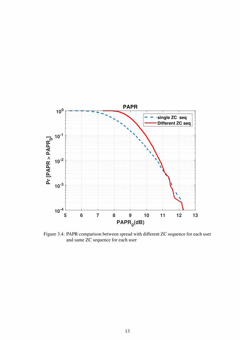
3.4 PAPR comparison between spread with different ZC sequence for each
user and same ZC sequence for each user . . . . . . . . . . . . . . 13
3.5 Comparison between patterned comb selection vs random comb selec-
tion when no of users =4 . . . . . . . . . . . . . . . . . . . . . . . 15
3.6 Comparison between patterned comb selection vs random comb selec-
tion when no of users =8 . . . . . . . . . . . . . . . . . . . . . . . 15
3.7 PAPR at Satellite end . . . . . . . . . . . . . . . . . . . . . . . . . 16
3.8 Using random same sequence as a pilot symbol . . . . . . . . . . . 17
3.9 Using best chosen symbols combination for 32 or 16 users as a pilot
symbols . . . . . . . . . . . . . . . . . . . . . . . . . . . . . . . . 18
3.10 Using best chosen symbols as a pilot symbols for every user . . . . 18
4.1 RCS Reverse link-Receiver . . . . . . . . . . . . . . . . . . . . . . 22
4.2 Comparison between uncoded BER of QPSK and DQPSK . . . . . 22
4.3 Comparison between coded and uncoded BER of QPSK . . . . . . 23
4.4 Comparison between coded and uncoded BER of DQPSK . . . . . 24
vi
Page 9
ABBREVIATIONS
CCE Common channel estimation
CDMA Code Division Multiple Access
CFR Channel frequency response
CRC Cyclic Redundancy Check
Cp Cyclic prefix
CSI Cyclic State information
DQPSK Differential Quadrature Phase Shift Keying
FFT Fast Fourier transform
IBI Interblock interference
IFFT Inverse fast Fourier transform
ISI Inter symbol interference
MA Multiple Access
NF Noise floor
PAPR Peak power to average power ratio
PRACH Physical Random Access Channel
QPSK Quadrature Phase Shift Keying
RCS Reliable Covert Satellite Communication
SI-OFDM spread interleaved orthogonal frequency-division multiplexing
SNR signal to noise ratio
UE User end
ZC Zadeoff-chu
ZFE Zero Forcing Equalizer
vii
Page 10
NOTATION
θ Angle
viii
Page 11
CHAPTER 1
Introduction
The objective of this project is to design waveform while accounting for various power
constraints in the reverse link (multi-point to point) using a communication satellite’s
transponder. The primary goal of this communication link is to provide reliability with a
low probability of detection and interception (LPD/LPI). The system can support users
spread over vast geographical areas. The reverse link handles Communication between
various User terminals to Hub through orthogonal multiple access channel using the
spread and Interleaved OFDMA(S-IOFDMA) technique. Most transponders operate on
a bent pipe principle, transmitting back to Earth with only amplification and shift from
downlink to Uplink frequency and vice versa.
Data signals are being spread by spreading sequence to keep it below noise floor
(NF), which provides covertness to the system. An intruder can not distinguish whether
only noise is present or noise and signal both are present because signal power is below
the NF. Due to covertness advantage, SNR is very low in the pre-processing scenario
without compromising the signal quality. Due to the Spreading gain, repetition gain,
FEC gain, and Narrow-banding Gain, the SNR boost during post-processing at receiver
and reliability is ensured.
The system requires four kbps data per user to Hub, and the same requirement holds
vice-versa.. The number of users simultaneously supported by the system is 32. This
work involves the design of the reverse link of Reliable Covert Satellite Communication
system. The design of reverse link supports Communication from a User terminal to
Hub uses spread Interleaved OFDMA technique for orthogonal multiple access.
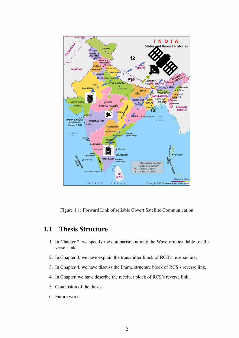
RCS requires the Hub and User device to operate over two different carrier frequen-
cies. As shown in figure 1.3 f1 and f1’ being carrier frequency separated by 18 MHz
and f2 and f2’ is another set of carrier frequency separated by 18 MHz. The channel
bandwidth for f1 and f1’ will be 17.875 MHz each separated by a 250 kHz guard band,
similarly for f2 and f2’ .f1 and f2’ are used for reverse link, users are transmitting over
f1, and Hub is using f2’ similarly f2 and f1’are used for the forward link.
Page 12
Figure 1.1: Forward Link of reliable Covert Satellite Communication
1.1 Thesis Structure
1. In Chapter 2, we specify the comparison among the Waveform available for Re-
verse Link.
2. In Chapter 3, we have explain the transmitter block of RCS’s reverse link.
3. In Chapter 4, we have discuss the Frame structure block of RCS’s reverse link.
4. In Chapter, we have describe the receiver block of RCS’s reverse link.
5. Conclusion of the thesis.
6. Future work.
2
Page 13
Figure 1.2: Reverse Link of reliable Covert Satellite Communication layout
3
Page 14
Figure 1.3: Reliable Covert Satellite Communication layout
Multiple access SI-OFDMA
Transponder Signal bandwidth available 18 MHz
Frame duration 1000 ms
Useful Symbol duration 131.072 µ s )
Chip duration(Tc) 64 ns (0.064 µ s)
Cyclic prefix (Tcp) 8192 ns (8.192 µ s)
Excess Bandwidth factor for RC pulse-shaping 0.144
Occupied Bandwidth ((1+ β ) / Tc) 17.875 MHz
Modulation QPSK / 4-QAM
FEC Matrix Parity with CRC, Rate 80/108
Bit Rate 4 kbps (per user)
No of user being supported simultaneously 32
Spreading factor 64
Repetition factor 2
frequency of operation Ku-band (10 GHz to 14 GHz)
Table 1.1: The reverse link design Specifications
4
Page 15
CHAPTER 2
Waveform choice for Reverse Link
2.1 OFDMA
OFDMA is a MA technique which can assign a different number of subcarriers to indi-
vidual users. It transmits the data over many orthogonal narrowband subcarriers instead
of transmitting the signal over the entire bandwidth. It permits simultaneous transmis-
sion from multiple users. The orthogonality of different users’ signals is maintained
even for transmission over time-dispersive channels. In OFDMA, inter-symbol inter-
ference (ISI) can be avoided by using Cyclic prefix. OFDMA gives low computational
complexity due to its implementation using Fast Fourier Transform (FFT) algorithm.
However,multicarrier-based MA schemes like OFDMA suffers from high peak to aver-
age ratio. Thus, power amplifiers with a large dynamic range are required. It is required
that the mobiles use as little battery power as possible. We can not use heavy power
amplifers at UE but clearly power is not an issue at base stations. ODFMA is not a good
choice for UE to hub link
2.2 Block modulated CDMA
In forward Link, Block modulated CDMA is used as a wave form but we can not the use
same Block modulated CDMA wave form for reverse link due to the following reasons
1. As every user’s data passes through an FIR channel, orthogonality across users
will be lost at receiver.
2. To resolve orthogonality among users,Hub has to compensate for all the channels
which is not feasible.
Page 16
2.3 SI-OFDMA
I-OFDMA can be derived from a single carrier based MA like DS-CDMA perspective
by using frequency-domain orthogonal signature sequences (FDOSS) as well as, it can
be obtained from a multicarrier-based MA scheme like OFDMA by the introduction of
an interleaved subcarrier allocation
. I-OFDMA combines many advantages of single and multicarrier-based MA schemes.
i)It produces a multi-carrier signal at the receiver, which provides orthogonality in
the frequency domain. ii)As a single-carrier scheme, each user has a very low trans-
mit PAPR signal compare to PAPR of multi-carrier. It provides benefits like the low
complexity, especially at the transmitter side, which is lower than the transmitter of
OFDMA, the low PAPR of the transmit signal, and the excellent power efficiency. I-
OFDMA scheme has advantages of CDMA as well as OFDMA. Due to CDMA like
properties, it has low complexity for signal generation, low PAPR, and high-frequency
diversity. Due to OFDMA type properties, it has low complexity for user separation
and low computational complexity for equalization.
I-ODFMA provides PAPR similar to the CDMA. I-ODFMA is an excellent choice for
the reverse link because high PAPR is a critical issue at the satellite end. To fulfill the re-
quirement of covertness and to meet Low probability of detection or low probability of
interception signal should be spread with spreading sequence. Spreading the data with
spreading sequence and implement it on the I-OFDMA, so the name of the waveform
is I-OFDMA
2.3.1 Frame Structure
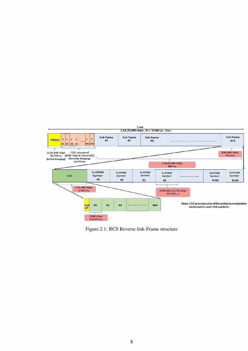
In the reverse link design, every UE will transmit 2,704 different QPSK symbols (16
subframes × 169 complex data symbols) repeating twice which allows for 3 dB gain.
In the frame structure design, the chip duration is 0.064 µs, and the total number of
chips is 1,56,25,000. The PRACH structure has 14,95,848 chips, which corresponds to
95.734 ms. PRACH design is planned with a pool of ZC sequences where a new UE
joining network will transmit one of the sequences with 4096 chips as a PRACH signal
for ranging.
Periodic ranging has 4096 chips duration of the Zadeoff-chu sequence repeated twice
6
Page 17
for each UE.This ensures that all the UEs have been ranged such a way that relative
delay between first and last arriving uplink signal is less than cyclic prefix.
Each frame consists of 16 subframes(1,38,67,008chips and 888ms duration), and each
subframe has 8,66,688 chips and duration of 55.5 ms . Every subframe has one Com-
mon Channel Estimation (CCE) and 169 different SI-OFDMA symbols carrying User
data. In every frame, SI-OFDM symbols repeated twice, making the total number of
SI-OFDM symbols 338. Each SI-OFDMA symbol consists of 2176 (2048 Data+128
CP) chips.
CCE will have 1,31,200 chips. CCE consists of a pilot SI-OFDMA symbol from each
UE, which was repeated 64 times for an 18dB boost in SNR for high-quality channel
estimation.
7
Page 18
Figure 2.1: RCS Reverse link-Frame structure
8
Page 19
CHAPTER 3
Transmitter Block
Figure 3.1: RCS Reverse link - Transmitter
3.1 FEC using CRC and MPCC
The reverse link works on spread interleaved OFDMA(SI-OFDMA).Each user’s data
from UE is encoded by the Forward error correction block (80/108 coding rate) to
achieve an additional 2 dB to 3 dB coding gain.
This FEC scheme used CRC and two-dimensional parity-check codes (Matrix Parity
Check Code (MPCC)) for the error control. The technique is able to detect and correct
all one and two-bit errors in a given code block. First data bits are encapsulated with
CRC and after that the matrix formed is used to compute 2-D parity codes.
The decoder has two sections, first is the error detection and evaluation of error cor-
rection possibility, second is Error correction. The hard decision decoder significantly
reduces the computational load and decoder power requirement.
Page 20
3.1.1 Encoder
The CRC polynomial selection is a critical part of the syndrome generation and error
detection. Calculate CRC for each user’s N bits stream then reshape vector into M time
N matrix(M=11 and N=8). Compute row and column parity for data pits, including
CRC bits.
3.1.2 Decoder
For decoding, a lookup table saves syndromes for all single-bit errors. Two-bit error
(few typical combinations for three-bit error) corrections are possible for hard deci-
sion decoder implementation. Calculate CRC syndrome for the received bitstream,
excluding parity and CRC bits, then evaluate Row and Column parity bits for received
bits, including CRC bits. In case errors are more than two bits,block decoding will
failed. Single-bit error correction are performed when row and column parity check
indicate single bit error, and the syndrome matches the reference syndrome value from
the lookup table. This reference syndrome is gathered from the location pointed by
parity check results. Seven different types of two-bit errors can occur in the received
data. Each class is specified by the row and column parity check results. For every kind
of two-bit error, the parity check result gives a small set of possible error locations
3.2 Modulation
The reverse link works on spread-interleaved OFDMA(SI-OFDMA) with differential
QPSK modulation, which supports a data rate of 4 kbps for each user. The FEC en-
coded data stream is mapped to differential modulated QPSK symbols. In Differential
quadrature phase-shift-keying (DQPSK), the information is conveyed by the absolute
phase difference of each symbol with previous symbol. In DQPSK, the information
sent by establishing a particular phase of one symbol relative to the previous symbol.
DQPSK provides a promising alternative as it, like QPSK, transmits 2 bits per symbol.
Hence, the symbol rate is half the bit rate. DQPSK is used instead of QPSK to avoid
phase error caused by residual frequency offset.
10
Page 21
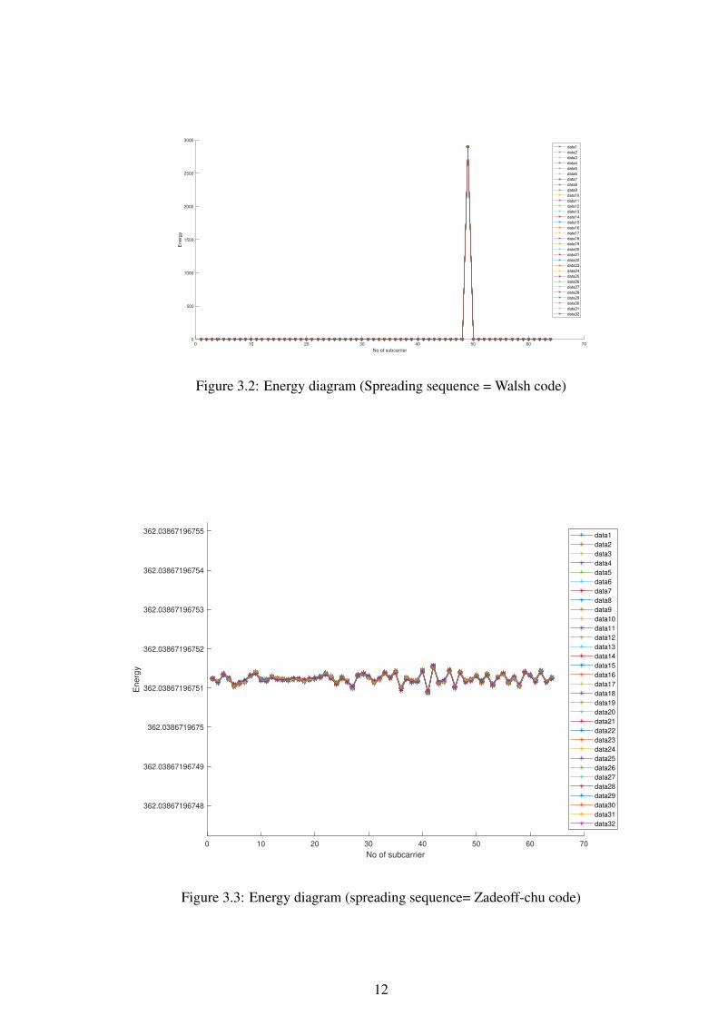
3.3 Spreading sequence
Data symbols are spread by spreading sequences of length 64 to provide covertness in
RCS. Walsh code, Zadoff-chu sequence, and others are available options. Why did we
choose Zadoff-chu as a spreading sequence? When Walsh code is used as a spreading
sequence, energy is concentrated at a single sub-carrier for all the users. If deep fade
occurs at that subcarrier, Signal will be lost because all the energy is confined at a single
subcarrier. If Zadoff-chu used as a spreading sequence, the energy spreads among the
64 available sub-carriers. As shown in Figures 3.2 and 3.3. The basic form of the
Zadoff-chu sequence can be created by the formula as shown below
zseq = exp(−1i ∗ pi ∗ u ∗ n. ∗ (n+ cf + 2 ∗ q)/Nzc)
Where
q = 0, n = 0 : NZC − 1,
0 < u < NZC and gcd(NZC, u) = 1,
cf = mod(Nzc, 2),
NZC = length of sequence.
The data symbol stream first is spread by the Zadoff-Chu by a length 64 ZC spread-
ing sequence. Spreading of data symbols is needed to provide low signal power because
the RCS system works on low signal power, which is below the noise floor to provide
covertness of the system. We spread each user data symbol by best chosen Zadoff-chu
spreading sequence to give an overall low PAPR signal at the Satellite end. Individ-
ual PAPR of each user is close to unity, but when they are combined at the satellite
end, PAPR increases drastically. If we use different Zadoff-Chu spreading sequences
for every user, The system will get higher PAPR results as compare to using single
Zadeoff-chu for every user. Unlike the Forward link, the Reverse link uses spreading
sequences to provide covertness to the system, not orthogonality. As a result, we can
use a single Zadoff-Chu sequence as a spreading sequence for every user.
11
Page 22
0 10 20 30 40 50 60 70
No of subcarrier
0
500
1000
1500
2000
2500
3000
En
erg
y
data1
data2
data3
data4
data5
data6
data7
data8
data9
data10
data11
data12
data13
data14
data15
data16
data17
data18
data19
data20
data21
data22
data23
data24
data25
data26
data27
data28
data29
data30
data31
data32
Figure 3.2: Energy diagram (Spreading sequence = Walsh code)
0 10 20 30 40 50 60 70
No of subcarrier
362.03867196748
362.03867196749
362.0386719675
362.03867196751
362.03867196752
362.03867196753
362.03867196754
362.03867196755
En
erg
y
data1
data2
data3
data4
data5
data6
data7
data8
data9
data10
data11
data12
data13
data14
data15
data16
data17
data18
data19
data20
data21
data22
data23
data24
data25
data26
data27
data28
data29
data30
data31
data32
Figure 3.3: Energy diagram (spreading sequence= Zadeoff-chu code)
12
Page 23
5 6 7 8 9 10 11 12 13
PAPR0(dB)
10-4
10-3
10-2
10-1
100
Pr
[PA
PR
> P
AP
R0]
PAPR
single ZC seq
Different ZC seq
Figure 3.4: PAPR comparison between spread with different ZC sequence for each user
and same ZC sequence for each user
13
Page 24
3.4 Comb selection
Each user’s data block is repeated 32 times to accommodate 32 users, followed by
appropriate comb allocation at every user terminal. Allocating comb to each user is
done by multiplying ej∗k∗n where k is the comb location of users. Comb allocation in
the time domain leads to a shift to the user data in the frequency domain, which makes
all users orthogonal to each other. Appropriate comb location pattern is all users must
be equidistance from each other to get the best PAPR result
1. Comb index (K) varying from 0 to user-1 in our case max no user which can be
supported by the system is 32 (if users are integer multiple of 2)
n is varying from 0 to n-1
2. K=(user/32)*n
Example =>if users=4 best possible comb index are 0 ,8 ,16 and 24 .
if users=8 best possible comb index are 0 ,4 ,8 ,12 ,16 ,20 ,24 and 28
3. (if users are odd)
Example => if user=5 best possible comb index are 0 ,8 ,16 , 24 and 4
if users=9 best possible comb index are 0 ,4 ,8 ,12 ,16 ,20 ,24 ,28 and 2
In case all 32 users are present, we don’t have any choice to get low PAPR by using
the appropriate comb selection method because it doesn’t matter in which order we
choose the comb but distance between comb matter. The system is not fully loaded
then make comb selection like every user’s data must be equidistance to each other.
3.5 Compensation frequency offset
In reverse link, every chip (data, pilot) transmitted by UE must be sent after frequency
compensation (shown as for every user) represented by ejθ in fig, which is estimated
through the forward link. Unlike the forward link, the reverse link scenario is multi-
point to point where multiple UEs transmit at the same time, and each user’s data has a
different frequency offset error, which is difficult to handle at hub’s side. To avoid inter-
symbol interference (ISI) through the insertion of a cyclic prefix (CP) at the transmitter
and its removal at the receiver. Pulse shaped (Raised cosine window) SI-OFDMA is
used as per the framing structure, then converted to analog form, mapped onto the
carrier, and transmitted.
14
Page 25
3 4 5 6 7 8
PAPR0(dB)
10-2
10-1
100
Pr
[PA
PR
> P
AP
R0]
No of User =4
best possible comb
Randomly choosen comb
X 6.88
Y 0.2201
Figure 3.5: Comparison between patterned comb selection vs random comb selection
when no of users =4
3 4 5 6 7 8 9 10 11
PAPR0(dB)
10-4
10-3
10-2
10-1
100
Pr
[PA
PR
> P
AP
R0]
No of User =8
Best Possible comb location
Randomly choosen comb location
Figure 3.6: Comparison between patterned comb selection vs random comb selection
when no of users =8
15
Page 26
0 2 4 6 8 10 12 14
PAPR0 (dB)
10-4
10-3
10-2
10-1
100
Pr
[PA
PR
> P
AP
R0]
PAPR (qpsk spread with ZC)
32 USERS
16 USERS
8 USERS
4 USERS
2 USERS
1 USER
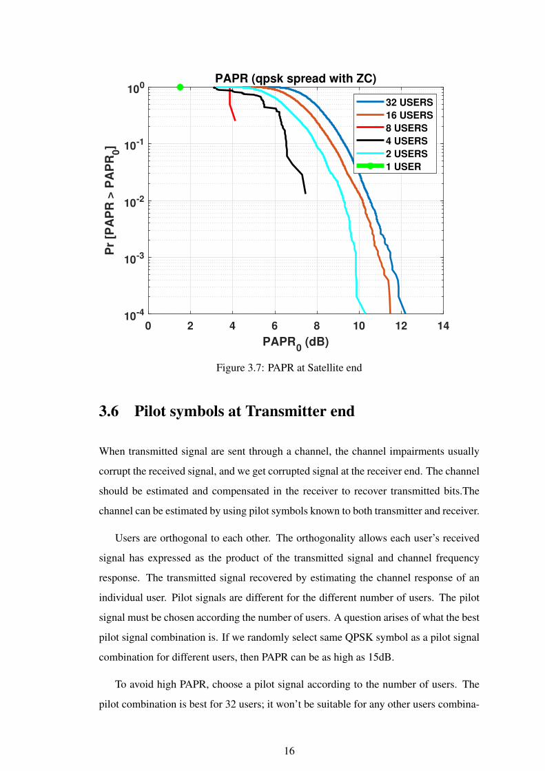
Figure 3.7: PAPR at Satellite end
3.6 Pilot symbols at Transmitter end
When transmitted signal are sent through a channel, the channel impairments usually
corrupt the received signal, and we get corrupted signal at the receiver end. The channel
should be estimated and compensated in the receiver to recover transmitted bits.The
channel can be estimated by using pilot symbols known to both transmitter and receiver.
Users are orthogonal to each other. The orthogonality allows each user’s received
signal has expressed as the product of the transmitted signal and channel frequency
response. The transmitted signal recovered by estimating the channel response of an
individual user. Pilot signals are different for the different number of users. The pilot
signal must be chosen according the number of users. A question arises of what the best
pilot signal combination is. If we randomly select same QPSK symbol as a pilot signal
combination for different users, then PAPR can be as high as 15dB.
To avoid high PAPR, choose a pilot signal according to the number of users. The
pilot combination is best for 32 users; it won’t be suitable for any other users combina-
16
Page 27
0 5 10 15 20 25 30
No of users
0
2
4
6
8
10
12
14
16
PA
PR
(dB
)
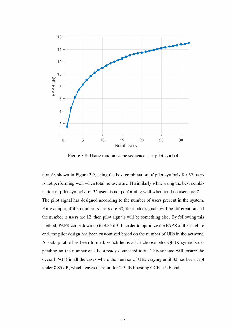
Figure 3.8: Using random same sequence as a pilot symbol
tion.As shown in Figure 3.9, using the best combination of pilot symbols for 32 users
is not performing well when total no users are 11.similarly while using the best combi-
nation of pilot symbols for 32 users is not performing well when total no users are 7.
The pilot signal has designed according to the number of users present in the system.
For example, if the number is users are 30, then pilot signals will be different, and if
the number is users are 12, then pilot signals will be something else. By following this
method, PAPR came down up to 8.85 dB. In order to optimize the PAPR at the satellite
end, the pilot design has been customized based on the number of UEs in the network.
A lookup table has been formed, which helps a UE choose pilot QPSK symbols de-
pending on the number of UEs already connected to it. This scheme will ensure the
overall PAPR in all the cases where the number of UEs varying until 32 has been kept
under 8.85 dB, which leaves us room for 2-3 dB boosting CCE at UE end.
17
Page 28
1 5 10 15 20 25 30 32
No. of users
1
2
3
4
5
6
7
8
9
PA
PR
(d
B)
Pilot symbols (QPSK) optimized for lower PAPR
in multiple users presence
32 users combination
16 users combination
Figure 3.9: Using best chosen symbols combination for 32 or 16 users as a pilot sym-
bols
0 5 10 15 20 25 30 35
No of users
1.5
2
2.5
3
3.5
4
4.5
5
5.5
6
PA
PR
(dB
)
X 18
Y 5.885
Figure 3.10: Using best chosen symbols as a pilot symbols for every user
18
Page 29
CHAPTER 4
Receiver Block
4.1 Timing synchronization
Timing synchronization is a necessity for any wireless communication system to work
correctly. In Timing synchronization, the receiver node determines the correct instants
incoming signals sample. Timing synchronization involves cross-correlation with all
the assigned Zadoff-Chu sequences for existing UEs in the network. Cross-correlation
ensures that all the UEs have ranged in such a way that relative delay between first and
last arriving uplink signal is less than cyclic prefix. If the channel delay spread is shorter
than the duration of the CP, no ISI occurs. According to the first and last peak from the
cross-correlation of Zadoff-Chu (ZC), we can choose IBI to free the FFT window.
The cyclic prefix (CP) is an identical copy of some portion from the end of the sym-
bol. The cyclic prefix used to eliminate intersymbol interference(ISI) from the previous
symbol. The insertion of a cyclic prefix (CP) occurs at the transmitter and its removal
at the receiver.
4.2 Channel estimation
In general, the channel estimation can be done by using a preamble or pilot symbols
known to both transmitter and receiver. The transmitted signal recovered by estimating
the channel response. Channel state information (CSI) is obtained by adding pilot sym-
bols at the start of each subframe symbol.
In every start of a subframe, channel frequency response (CFR) estimation for every
UE to Hub link has done first by coherently adding 64 copies of received pilot symbols
to boost SNR by 18 dB and followed by FFT. Then, each UE’s received comb has been
separated and multiplied by conjugate of UE-specific transmitted pilot fetch us CFR of
each UE. This estimated CFR also captures the additional phase error caused due to
shifting in the FFT window from a critical boundary.
Page 30
.
4.3 Zero forcing equalization
The technique of equalization to compensate for the effect of the channel, which distorts
the transmitted signal. Different kinds of equalizers have used for equalization depend-
ing upon the application of the system and upon the type of communication channel.
ZF equalizer is used to compensate for the effect of ISI.ZF is useful in mitigating the
ISI effect rather than induced noise in the signal.
As every data symbol has transmitted twice, It will provide extra 3dB gain. After taking
FFT, separate each UE specific comb from each replica. Equalize (ZFE) using every
UE’s respective estimated CFR and then coherently added with each other.
X = (HT )(HT H) ∗ Y
.
4.4 Zero interleaving
After completing the zero-forcing equalization (ZFE) process for all UEs. Every UE’s
equalized frequency response is interleaved with 32 zeros. To avoid any frequency shift
at the end, after zero interleavings, assign it to 1st user’s comb and then take IFFT. This
will gives 15 dB gain as every UE occupies a portion of the whole bandwidth.
.
4.5 De-spread and Decoding
Truncate 2048 IFFT output to first 64 chips, and de-spread with transmitted ZC fol-
lowed by mapping to closest DQPSK symbol. Spreading factor 64 added gain of ap-
prox 18.06 dB.Final symbol decisions will be made for individual UE through differen-
tial demodulation to previously received symbols.When the signal is passed through a
20
Page 31
noisy channel, DQPSK modulation is prone to errors while transmitting signals through
noisy channels than PSK. BER performance of DQPSK is approximately 3dB worse
than QPSK. Final symbol decisions will be made for individual UE through differential
demodulation to previously received symbols.
4.6 Post-Processing Gain
To provide the covertness system ensures that signal power will be below NF, but at the
same time, we don’t want to compromise the quality of the system. Due to the Spread-
ing factor gain, repetition factor gain, FEC gain, and Narrow-banding gain SNR boost
by almost 39.12 dB during post-processing at receiver and reliability have ensured.
Simulation Parameter Gain
Spreading gain(64-length) 18.06 dB
Narrow banding-Gain 15.05 dB
FEC MPCC and CRC 3 dB gain at 10(−5) uncoded BER
Repetition Gain 3 dB
total Gain 39.12 dB
Table 4.1: post-processing gain
4.7 Simulation results
System Level simulation parameters (Assumptions)
1. 100 % loaded system (All 32 users are present)
2. No short term fading.
3. No relative power difference among all users while their signal reaching Satellite
receiver end.
4. Timing information is assumed to be known.
5. No CFO error.
6. Two times repetition of data symbols is implemented for 3dB boost. No pilot
symbol’s power boost (both data and pilots are transmitted with equal power).
7. Each user sends 169 QPSK symbols repeated twice and 1000 such Monte Carlo
simulations has been performed to calculate average BER of the system for each
SNR.
21
Page 32
Figure 4.1: RCS Reverse link-Receiver
-40 -38 -36 -34 -32 -30 -28 -26 -24 -22 -20
Pre-processing SNR(dB)
10-7
10-6
10-5
10-4
10-3
10-2
10-1
100
Un
co
de
d B
ER
SNR Vs BER plot for DQPSK and QPSK Modualtion in delay Channel
DQPSK
QPSKX -36
Y 0.381
Figure 4.2: Comparison between uncoded BER of QPSK and DQPSK
22
Page 33
-40 -38 -36 -34 -32 -30 -28 -26 -24 -22
Pre-processing SNR(dB)
10-7
10-6
10-5
10-4
10-3
10-2
10-1
100
BE
R
QPSK with FEC
QPSK w/o FECX -36
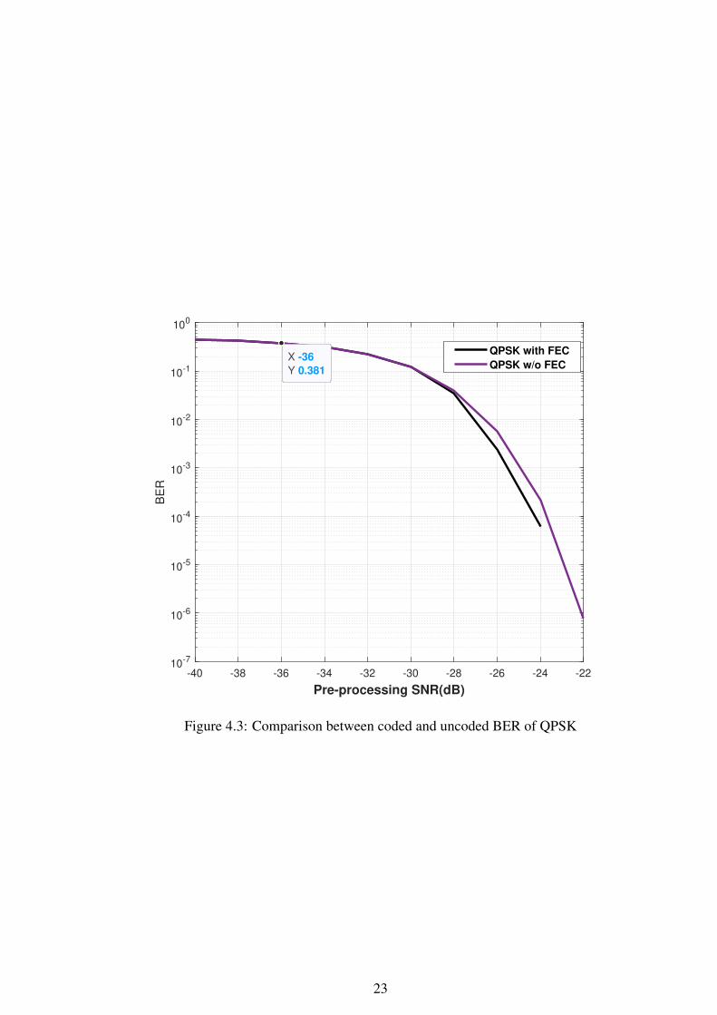
Y 0.381
Figure 4.3: Comparison between coded and uncoded BER of QPSK
23
Page 34
-40 -38 -36 -34 -32 -30 -28 -26 -24 -22 -20
Pre-processing SNR(dB)
10-7
10-6
10-5
10-4
10-3
10-2
10-1
100
BE
R
DQPSK with FEC
DQPSK w/o FEC
Figure 4.4: Comparison between coded and uncoded BER of DQPSK
24
Page 35
CHAPTER 5
Conclusion
• Reverse link or Uplink in this multi-point to point network using satellite as a
transponder in amplify and forward mode, achieved the required LPI/LPD goal
while supporting an user uplink data-rate of 4 Kbps per user.
• Mindful waveform design allowed to handle multipath and provided extra head-
room to accommodate small errors in uplink ranging.
• Efficient pilot design for channel estimation helped us to restrict the PAPR of the
multiple access signal received at satellite end approximately below 6dB for a
fully-loaded system, where as its absence of may shoot up the same PAPR to 15
dB in the worst case.
• In addition to it, the same PAPR has been controlled with the optimum comb
selection (user resource allocation) in the chosen multiple access scheme for the
data transmission in the reverse link.
Page 36
CHAPTER 6
Future Work
The additional system level aspects which needed more attention further is PRACH
processing and study the effect of residual CFO error over BER.
Has to finalize the multipath profile for the considered use case and how to incorporate
affects of the two satellite links (as amplify and forward being used in between user and
hub) on the measurement model.
Addition to this simulation study, a lab scale fool proof demo of the chosen signal
processing concepts is being built using Zynq Ultrascale MPSoc and ADRV 9009.
Page 37
REFERENCES
1. Chu, D. (1972). Polyphase codes with good periodic correlation properties (corresp.).
IEEE Transactions on Information Theory, 18(4), 531–532.
2. Frank, T., A. Klein, and E. Costa (2007). Ifdma: A scheme combining the advantages
of ofdma and cdma. IEEE Wireless Communications, 14(3), 9–17.
3. Frank, T., A. Klein, E. Costa, and E. Schulz, Ifdma - a promising multiple access
scheme for future mobile radio systems. In 2005 IEEE 16th International Symposium
on Personal, Indoor and Mobile Radio Communications, volume 2. 2005.
4. M. Madhusoodanan, S. and K.Giridhar, Power efficient flexible fec scheme for 5g iot
applications. In 2016 37th Wireless World Research Forum(WWRF) Meeting, volume 1.
2016.
27