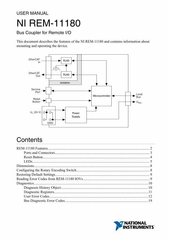
USER MANUAL NI REM-11180 Bus Coupler for Remote I/O This document describes the features of the NI REM-11180 and contains information about mounting and operating the device. EtherCAT In EtherCAT Out Service Port Reset Button Local Bus U bus Power Supply Microcontroller U L (24 V) GND RJ45 RJ45 Isolation Contents REM-11180 Features................................................................................................................ 2 Ports and Connectors........................................................................................................ 3 Reset Button...................................................................................................................... 4 LEDs................................................................................................................................. 5 Dimensions................................................................................................................................8 Configuring the Rotary Encoding Switch................................................................................. 8 Restoring Default Settings........................................................................................................ 9 Reading Error Codes from REM-11180 IOVs.......................................................................... 9 Diagnostics.............................................................................................................................. 10 Diagnosis History Object................................................................................................ 10 Diagnostic Registers........................................................................................................ 11 User Error Codes............................................................................................................. 12 Bus Diagnostic Error Codes............................................................................................ 19
Transcript
USER MANUAL
NI REM-11180Bus Coupler for Remote I/O
This document describes the features of the NI REM-11180 and contains information aboutmounting and operating the device.
a1, a2 Red 24 VDC (UL) Supply of logic voltage (internally jumpered)
b1, b2 Blue GND Reference potential of the supply voltage (internallyjumpered)
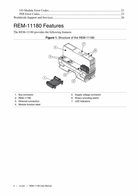
Figure 4. Service Interface
2
1
1. Label2. Service Interface
Note The service interface is a micro-USB port used for factory service andconfiguration. You do not need to connect to this port for normal operation.
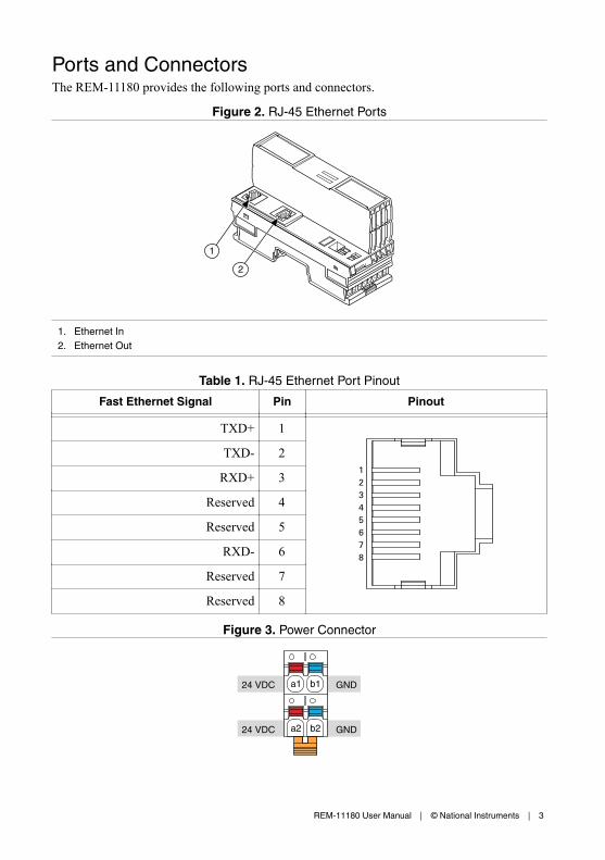
Reset ButtonPressing the reset button during normal operation restarts the bus coupler.
Figure 5. REM-11180 Reset Button
2
1
1. Label2. Reset button
4 | ni.com | REM-11180 User Manual
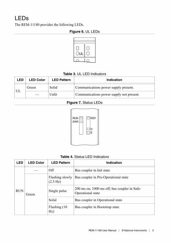
LEDsThe REM-11180 provides the following LEDs.
Figure 6. UL LEDs
UL
Table 3. UL LED Indicators
LED LED Color LED Pattern Indication
UL
Green Solid Communications power supply present.
— Unlit Communications power supply not present.
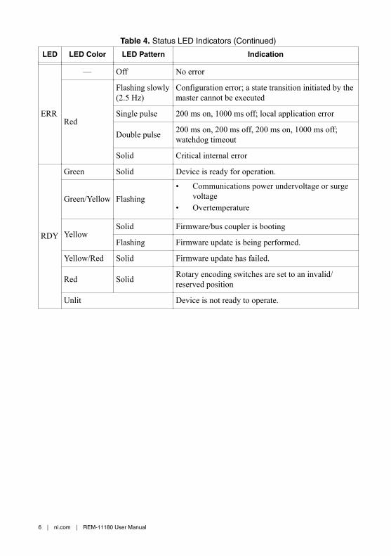
Figure 7. Status LEDs
RUNERR
RDY
DE
Table 4. Status LED Indicators
LED LED Color LED Pattern Indication
RUN
— Off Bus coupler in Init state
Green
Flashing slowly(2.5 Hz)
Bus coupler in Pre-Operational state
Single pulse 200 ms on, 1000 ms off; bus coupler in Safe-Operational state
Flashing Transmission or reception of Ethernet telegrams at EC IN /EC OUT.
— Off Connection not present at EC IN/EC OUT.
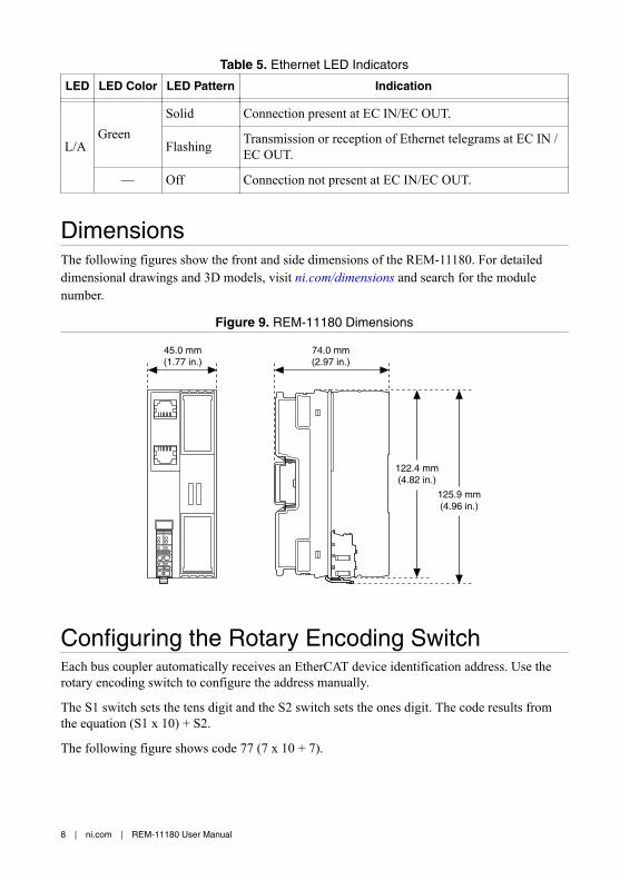
DimensionsThe following figures show the front and side dimensions of the REM-11180. For detaileddimensional drawings and 3D models, visit ni.com/dimensions and search for the modulenumber.
Figure 9. REM-11180 Dimensions
125.9 mm(4.96 in.)
122.4 mm(4.82 in.)
74.0 mm(2.97 in.)
45.0 mm(1.77 in.)
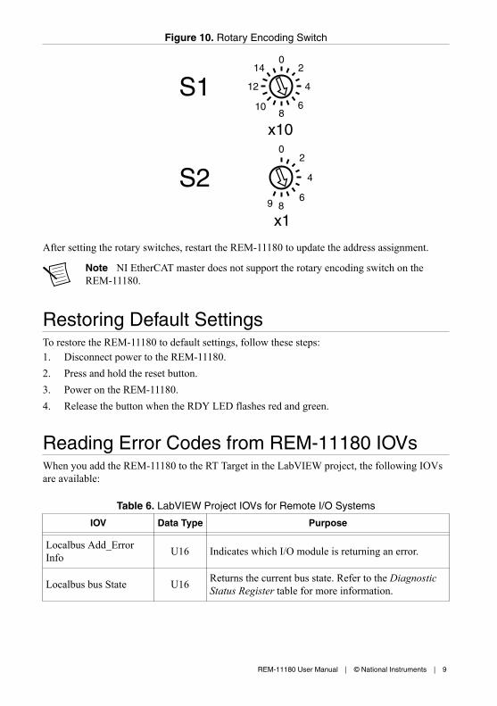
Configuring the Rotary Encoding SwitchEach bus coupler automatically receives an EtherCAT device identification address. Use therotary encoding switch to configure the address manually.
The S1 switch sets the tens digit and the S2 switch sets the ones digit. The code results fromthe equation (S1 x 10) + S2.
After setting the rotary switches, restart the REM-11180 to update the address assignment.
Note NI EtherCAT master does not support the rotary encoding switch on theREM-11180.
Restoring Default SettingsTo restore the REM-11180 to default settings, follow these steps:1. Disconnect power to the REM-11180.2. Press and hold the reset button.3. Power on the REM-11180.4. Release the button when the RDY LED flashes red and green.
Reading Error Codes from REM-11180 IOVsWhen you add the REM-11180 to the RT Target in the LabVIEW project, the following IOVsare available:
Table 6. LabVIEW Project IOVs for Remote I/O Systems
IOV Data Type Purpose
Localbus Add_ErrorInfo U16 Indicates which I/O module is returning an error.
Localbus bus State U16 Returns the current bus state. Refer to the DiagnosticStatus Register table for more information.
Table 6. LabVIEW Project IOVs for Remote I/O Systems (Continued)
IOV Data Type Purpose
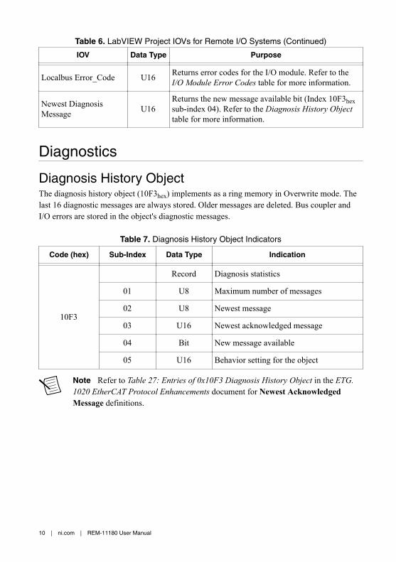
Localbus Error_Code U16 Returns error codes for the I/O module. Refer to the
I/O Module Error Codes table for more information.
Newest DiagnosisMessage U16
Returns the new message available bit (Index 10F3hexsub-index 04). Refer to the Diagnosis History Objecttable for more information.
Diagnostics
Diagnosis History ObjectThe diagnosis history object (10F3hex) implements as a ring memory in Overwrite mode. Thelast 16 diagnostic messages are always stored. Older messages are deleted. Bus coupler andI/O errors are stored in the object's diagnostic messages.
Table 7. Diagnosis History Object Indicators
Code (hex) Sub-Index Data Type Indication
10F3
Record Diagnosis statistics
01 U8 Maximum number of messages
02 U8 Newest message
03 U16 Newest acknowledged message
04 Bit New message available
05 U16 Behavior setting for the object
Note Refer to Table 27: Entries of 0x10F3 Diagnosis History Object in the ETG.1020 EtherCAT Protocol Enhancements document for Newest AcknowledgedMessage definitions.
10 | ni.com | REM-11180 User Manual
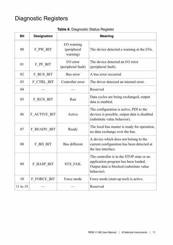
Diagnostic Registers
Table 8. Diagnostic Status Register
Bit Designation Meaning
00 F_PW_BITI/O warning(peripheralwarning)
The device detected a warning at the I/Os.
01 F_PF_BIT I/O error(peripheral fault)
The device detected an I/O error(peripheral fault).
02 F_BUS_BIT Bus error A bus error occurred.
03 F_CTRL_BIT Controller error The driver detected an internal error.
04 — — Reserved
05 F_RUN_BIT Run Data cycles are being exchanged, outputdata is enabled.
06 F_ACTIVE_BIT ActiveThe configuration is active, PDI to thedevices is possible, output data is disabled(substitute value behavior).
07 F_READY_BIT Ready The local bus master is ready for operation,no data exchange over the bus.
08 F_BD_BIT Bus differentA device which does not belong to thecurrent configuration has been detected atthe last interface.
09 F_BASP_BIT SYS_FAIL
The controller is in the STOP state or noapplication program has been loaded.Output data is blocked (substitute valuebehavior).
10 F_FORCE_BIT Force mode Force mode (start-up tool) is active.
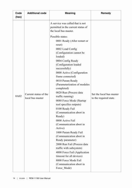
A service was called that is notpermitted in the current status ofthe local bus master.
Possible states:0001 Ready (After restart orreset)0002 Load Config(Configuration cannot beloaded)0004 Config Ready(Configuration loadedsuccessfully)0008 Active (Configurationframe connected)0010 Param Ready(Parameterization of modulescompleted)0020 Run (Process datatraffic running)0080 Force Mode (Startuptool specifies outputs)0100 Ready Fail(Communication abort inReady)0800 Active Fail(Communication abort inActive)1000 Param Ready Fail(Communication abort inReady parameter)2000 Run Fail (Process datatraffic with subsystem)4000 Force Fail (Applicationtimeout for all devices)8000 Force Mode Fail(Communication abort inForce_Mode)
Set the local bus masterto the required state.
14 | ni.com | REM-11180 User Manual
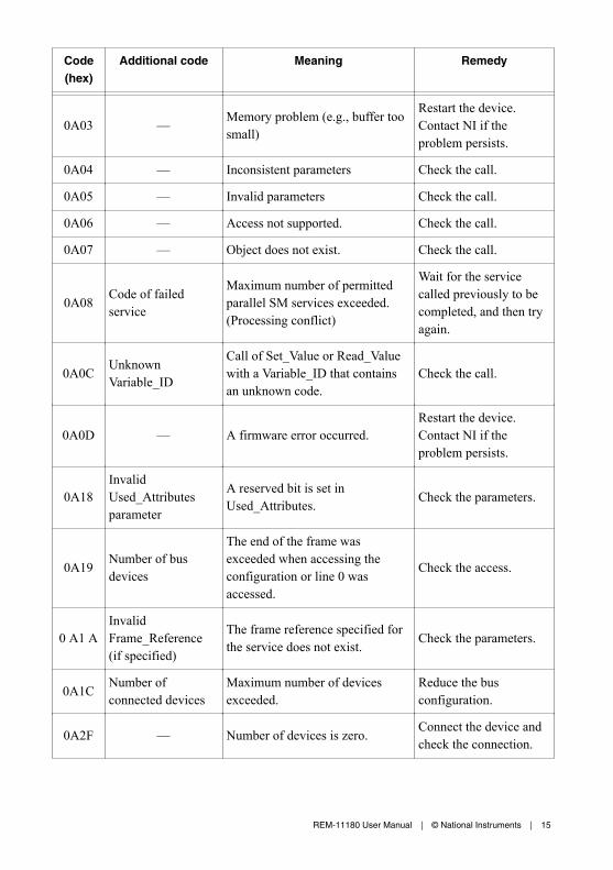
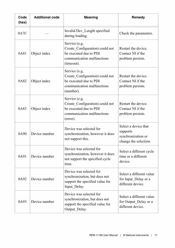
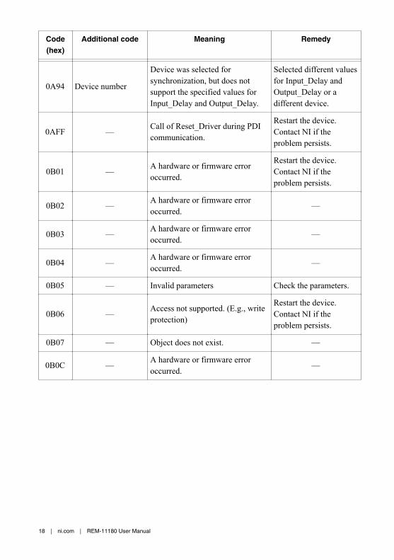
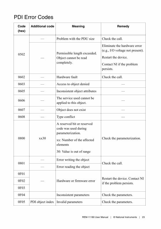
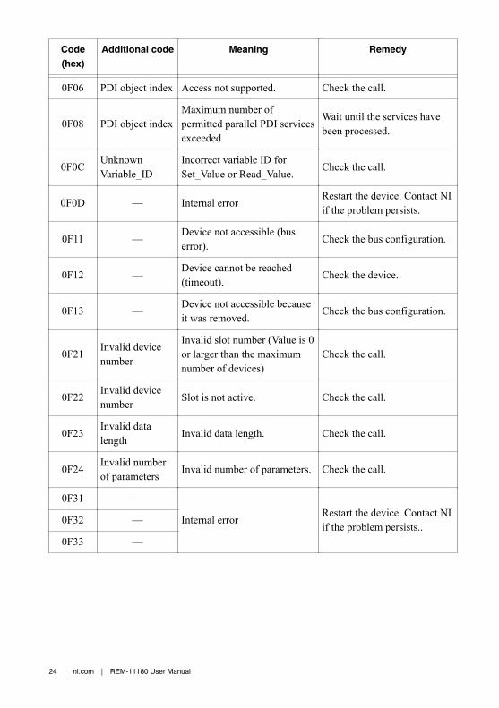
Code(hex)
Additional code Meaning Remedy
0A03 — Memory problem (e.g., buffer toosmall)
Restart the device.Contact NI if theproblem persists.
0A04 — Inconsistent parameters Check the call.
0A05 — Invalid parameters Check the call.
0A06 — Access not supported. Check the call.
0A07 — Object does not exist. Check the call.
0A08 Code of failedservice
Maximum number of permittedparallel SM services exceeded.(Processing conflict)
Wait for the servicecalled previously to becompleted, and then tryagain.
0A0C UnknownVariable_ID
Call of Set_Value or Read_Valuewith a Variable_ID that containsan unknown code.
Check the call.
0A0D — A firmware error occurred.Restart the device.Contact NI if theproblem persists.
0A18InvalidUsed_Attributesparameter
A reserved bit is set inUsed_Attributes. Check the parameters.
0A19 Number of busdevices
The end of the frame wasexceeded when accessing theconfiguration or line 0 wasaccessed.
Check the access.
0 A1 AInvalidFrame_Reference(if specified)
The frame reference specified forthe service does not exist. Check the parameters.
0A1C Number ofconnected devices
Maximum number of devicesexceeded.
Reduce the busconfiguration.
0A2F — Number of devices is zero. Connect the device andcheck the connection.
Device was selected forsynchronization, but does notsupport the specified values forInput_Delay and Output_Delay.
Selected different valuesfor Input_Delay andOutput_Delay or adifferent device.
0AFF — Call of Reset_Driver during PDIcommunication.
Restart the device.Contact NI if theproblem persists.
0B01 — A hardware or firmware erroroccurred.
Restart the device.Contact NI if theproblem persists.
0B02 — A hardware or firmware erroroccurred. —
0B03 — A hardware or firmware erroroccurred. —
0B04 — A hardware or firmware erroroccurred. —
0B05 — Invalid parameters Check the parameters.
0B06 — Access not supported. (E.g., writeprotection)
Restart the device.Contact NI if theproblem persists.
0B07 — Object does not exist. —
0B0C — A hardware or firmware erroroccurred. —
18 | ni.com | REM-11180 User Manual
Code(hex)
Additional code Meaning Remedy
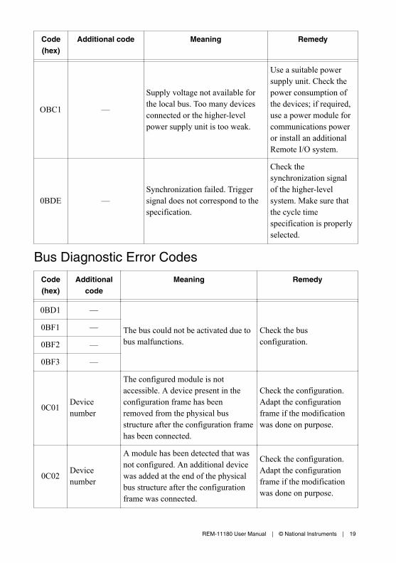
OBC1 —
Supply voltage not available forthe local bus. Too many devicesconnected or the higher-levelpower supply unit is too weak.
Use a suitable powersupply unit. Check thepower consumption ofthe devices; if required,use a power module forcommunications poweror install an additionalRemote I/O system.
0BDE —Synchronization failed. Triggersignal does not correspond to thespecification.
Check thesynchronization signalof the higher-levelsystem. Make sure thatthe cycle timespecification is properlyselected.
Bus Diagnostic Error Codes
Code(hex)
Additionalcode
Meaning Remedy
0BD1 —
The bus could not be activated due tobus malfunctions.
Check the busconfiguration.
0BF1 —
0BF2 —
0BF3 —
0C01 Devicenumber
The configured module is notaccessible. A device present in theconfiguration frame has beenremoved from the physical busstructure after the configuration framehas been connected.
Check the configuration.Adapt the configurationframe if the modificationwas done on purpose.
0C02 Devicenumber
A module has been detected that wasnot configured. An additional devicewas added at the end of the physicalbus structure after the configurationframe was connected.
Check the configuration.Adapt the configurationframe if the modificationwas done on purpose.
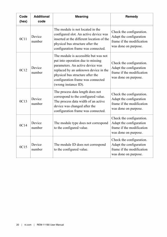
The module is not located in theconfigured slot. An active device wasinserted at the different location of thephysical bus structure after theconfiguration frame was connected.
Check the configuration.Adapt the configurationframe if the modificationwas done on purpose.
0C12 Devicenumber
The module is accessible but was notput into operation due to missingparameters. An active device wasreplaced by an unknown device in thephysical bus structure after theconfiguration frame was connected(wrong instance ID).
Check the configuration.Adapt the configurationframe if the modificationwas done on purpose.
0C13 Devicenumber
The process data length does notcorrespond to the configured value.The process data width of an activedevice was changed after theconfiguration frame was connected.
Check the configuration.Adapt the configurationframe if the modificationwas done on purpose.
0C14 Devicenumber
The module type does not correspondto the configured value.
Check the configuration.Adapt the configurationframe if the modificationwas done on purpose.
0C15 Devicenumber
The module ID does not correspondto the configured value.
Check the configuration.Adapt the configurationframe if the modificationwas done on purpose.
20 | ni.com | REM-11180 User Manual
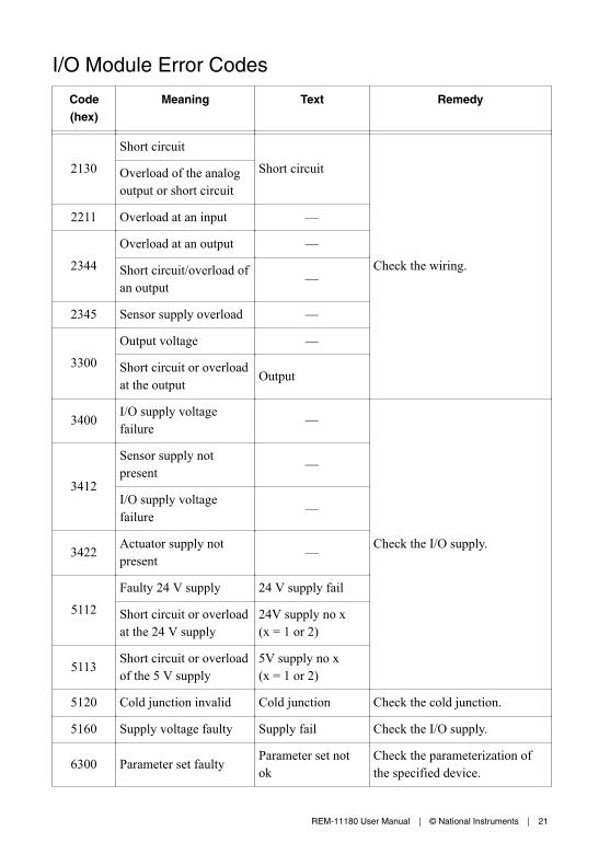
I/O Module Error Codes
Code(hex)
Meaning Text Remedy
2130Short circuit
Short circuit
Check the wiring.
Overload of the analogoutput or short circuit
2211 Overload at an input —
2344Overload at an output —
Short circuit/overload ofan output —
2345 Sensor supply overload —
3300Output voltage —
Short circuit or overloadat the output Output
3400 I/O supply voltagefailure —
Check the I/O supply.
3412
Sensor supply notpresent —
I/O supply voltagefailure —
3422 Actuator supply notpresent —
5112Faulty 24 V supply 24 V supply fail
Short circuit or overloadat the 24 V supply
24V supply no x(x = 1 or 2)
5113 Short circuit or overloadof the 5 V supply
5V supply no x(x = 1 or 2)
5120 Cold junction invalid Cold junction Check the cold junction.
5160 Supply voltage faulty Supply fail Check the I/O supply.
6300 Parameter set faulty Parameter set notok
Check the parameterization ofthe specified device.
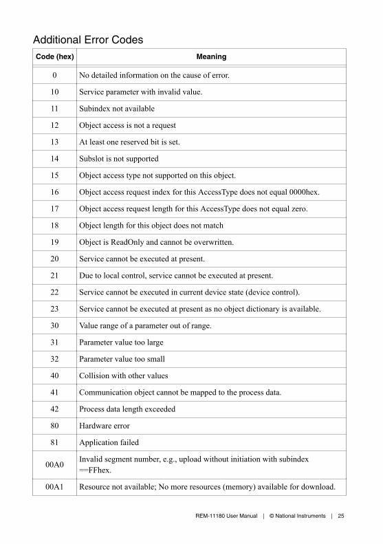
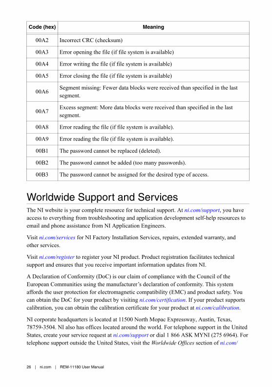
00A3 Error opening the file (if file system is available)
00A4 Error writing the file (if file system is available)
00A5 Error closing the file (if file system is available)
00A6 Segment missing: Fewer data blocks were received than specified in the lastsegment.
00A7 Excess segment: More data blocks were received than specified in the lastsegment.
00A8 Error reading the file (if file system is available).
00A9 Error reading the file (if file system is available).
00B1 The password cannot be replaced (deleted).
00B2 The password cannot be added (too many passwords).
00B3 The password cannot be assigned for the desired type of access.
Worldwide Support and ServicesThe NI website is your complete resource for technical support. At ni.com/support, you haveaccess to everything from troubleshooting and application development self-help resources toemail and phone assistance from NI Application Engineers.
Visit ni.com/services for NI Factory Installation Services, repairs, extended warranty, andother services.
Visit ni.com/register to register your NI product. Product registration facilitates technicalsupport and ensures that you receive important information updates from NI.
A Declaration of Conformity (DoC) is our claim of compliance with the Council of theEuropean Communities using the manufacturer’s declaration of conformity. This systemaffords the user protection for electromagnetic compatibility (EMC) and product safety. Youcan obtain the DoC for your product by visiting ni.com/certification. If your product supportscalibration, you can obtain the calibration certificate for your product at ni.com/calibration.
NI corporate headquarters is located at 11500 North Mopac Expressway, Austin, Texas,78759-3504. NI also has offices located around the world. For telephone support in the UnitedStates, create your service request at ni.com/support or dial 1 866 ASK MYNI (275 6964). Fortelephone support outside the United States, visit the Worldwide Offices section of ni.com/
niglobal to access the branch office websites, which provide up-to-date contact information,support phone numbers, email addresses, and current events.
Information is subject to change without notice. Refer to the NI Trademarks and Logo Guidelines at ni.com/trademarks forinformation on NI trademarks. Other product and company names mentioned herein are trademarks or trade names of theirrespective companies. For patents covering NI products/technology, refer to the appropriate location: Help»Patents in yoursoftware, the patents.txt file on your media, or the National Instruments Patent Notice at ni.com/patents. You can findinformation about end-user license agreements (EULAs) and third-party legal notices in the readme file for your NI product. Referto the Export Compliance Information at ni.com/legal/export-compliance for the NI global trade compliance policy and howto obtain relevant HTS codes, ECCNs, and other import/export data. NI MAKES NO EXPRESS OR IMPLIED WARRANTIES ASTO THE ACCURACY OF THE INFORMATION CONTAINED HEREIN AND SHALL NOT BE LIABLE FOR ANY ERRORS. U.S.Government Customers: The data contained in this manual was developed at private expense and is subject to the applicablelimited rights and restricted data rights as set forth in FAR 52.227-14, DFAR 252.227-7014, and DFAR 252.227-7015.


![NEW ITEM INFORMATION 11180 M Il EL121 EL122 ...NEW ITEM INFORMATION 11180 M Il EL121 EL122 GReenLLDÆ]D€ ¥15,900- *173-0014 8-4 Title GMNews17年03月発表D_4c_cs4(JRE653系しらゆき)](https://static.documents.pub/doc/80x56/5ec4fe39be92464bde029be5/new-item-information-11180-m-il-el121-el122-new-item-information-11180-m-il.jpg)


