LIMITED WARRANTY AND LIMITATION OF LIABILITY BY USING THIS SOFTWARE PRODUCT IN ANY MANNER, YOU ARE AGREEING TO ACCEPT THE FOLLOWING TERMS AND CONDITIONS.
Fluke Corporation (Fluke) grants you a non-exclusive right to use Fluke NORMA View software (Product) on a single PC or on multiple PCs. This grant of license does not include the right to copy, modify, rent, lease, sell, transfer or distribute the Product or any portion thereof. You may not reverse engineer, decompile, or disassemble the Product.
Fluke warrants that the Product will perform in its intended environment substantially in accordance with the accompanying written materials for a period of 90 days from the date of license acceptance. Fluke does not warrant any downloading errors or that the Product will be error free or operate without interruption.
FLUKE DISCLAIMS ALL OTHER WARRANTIES, EITHER EXPRESS OR IMPLIED, BUT NOT LIMITED TO IMPLIED WARRANTIES OF MERCHANTABILITY AND FITNESS FOR A PARTICULAR PURPOSE, WITH RESPECT TO THE SOFTWARE AND THE ACCOMPANYING WRITTEN MATERIALS. In no event shall Fluke be liable for any damages whatsoever (including, without limitation, indirect, consequential, or incidental damages, damages for loss of business profits, business interruption, loss of business information, or other pecuniary loss) arising out of the use of or inability to use this Product, even if Fluke has been advised of the possibility of such damages.
Fluke CorporationP.O. Box 9090 Everett, WA 98206-9090 U.S.A.
Fluke Europe B.V.P.O. Box 1186 5602 BD Eindhoven The Netherlands
11/2001
To register your product online, visit http://register.fluke.com/.
i
Table of Contents
Chapter Title Page
1 Remote Control Basics ....................................................................... 1-1
Introduction ........................................................................................................ 1-3 Getting Started ................................................................................................... 1-3
Switchover to Remote Control........................................................................... 1-4 Indications during Remote Control .................................................................... 1-4 Return to Manual Operation .............................................................................. 1-5
Structure and Syntax of Device Messages ......................................................... 1-6 Introduction to SCPI ...................................................................................... 1-6 Structure of Commands ................................................................................. 1-6 Common Commands ..................................................................................... 1-6 Device-Specific Commands .......................................................................... 1-6
Hierarchy ................................................................................................... 1-6 Optional Key Word ................................................................................... 1-7 Long and Short Form ................................................................................ 1-8 Parameters ................................................................................................. 1-8 Numerical Suffix ....................................................................................... 1-8
Structure of Command Lines ......................................................................... 1-8 Responses to Queries ..................................................................................... 1-9 Parameters ..................................................................................................... 1-10
Numerical values ....................................................................................... 1-10 Boolean Parameters ................................................................................... 1-10 Text ........................................................................................................... 1-10 Strings ....................................................................................................... 1-11 Block data ................................................................................................. 1-11
Overview of Syntax Elements ....................................................................... 1-11 Instrument Model and Command Processing .................................................... 1-11
Input Unit ...................................................................................................... 1-12 Command Recognition .................................................................................. 1-12
Remote Control Users Guide
ii
Data Set and Instrument Hardware ................................................................ 1-13 Status Reporting System ................................................................................ 1-13 Output Unit .................................................................................................... 1-13 Command Sequence and Command Synchronization ................................... 1-14
2 Status Reporting System .................................................................... 2-1
Introduction ........................................................................................................ 2-3 Structure of an SCPI Status Register ................................................................. 2-3 Overview of the Status Registers ....................................................................... 2-5 Description of Status Registers .......................................................................... 2-6
Status Byte (STB) and Service Request Enable Register (SRE) ................... 2-6 Event Status Register (ESR) and Event Status Enable Register (ESE) ......... 2-7
Application of the Status Reporting System ...................................................... 2-10 Service Request, Making Use of the Hierarchy Structure (GPIB only) ........ 2-10 Serial Poll (GPIB only) ................................................................................. 2-11 Query by Means of Commands ..................................................................... 2-11 Error-Queue Query ........................................................................................ 2-11 Resetting Values of the Status Reporting System ......................................... 2-11
Introduction ........................................................................................................ 6-3 Initialize Interface .............................................................................................. 6-3 Initialize Instrument ........................................................................................... 6-5 Perform Simple Power Measurement ................................................................ 6-6 U, I, P Measurement .......................................................................................... 6-9 Continuous Power Measurement ....................................................................... 6-11 U, I, P Measurement over Ethernet Interface without VISA Library ................ 6-14 U, I, P Measurement over RS-232 Interface without VISA Library ................. 6-19
v
List of Tables
Table Title Page
1-1. Synchronization by means of *OPC, *OPC? and *WAI ....................................... 1-14 2-1. Status Register Bits ................................................................................................ 2-6 2-2. Event Status Register Bits ...................................................................................... 2-7 2-3. STATus.OPERation Register Bits ......................................................................... 2-8 2-4. STATus:QUEStionable Register Bits .................................................................... 2-9 2-5. STATus:QUEStionable:CURRent Register Bits ................................................... 2-9 2-6. STATus:QUEStionable:VOLTage Register Bits ................................................... 2-10 2-7. Resettting Instrument Functions ............................................................................. 2-12 3-1. Interface Functions ................................................................................................. 3-5 3-2. Universal Commands ............................................................................................. 3-5 3-3. Addressed Commands ............................................................................................ 3-6 3-4. Control Characters for RS-232-C Interface............................................................ 3-8
Remote Control Users Guide
vi
vii
List of Figures
Figure Title Page
1-1. Tree Structure of SCPI Command Systems Using INPut system as Example ....... 1-7 1-2. Device Model for Remote Control via the Remote Control Interface. .................. 1-12 2-1. Status Register Model ............................................................................................ 2-3 2-2. Minimum Reporting Structure Required by SCPI ................................................. 2-5 3-1. Pin Assignment of IEC/IEEE-Bus Interface .......................................................... 3-3 3-2. Pin Assignment of RS-232-C Interface .................................................................. 3-7 3-3. Wiring of Data, Control, and Signalling Lines for Hardware Handshake ............. 3-9 3-4. Pin Assignment of IEEE 802.3 (Ethernet) Interface (RJ-45 Connector) ............... 3-10 3-5. IEEE 802.3 (Ethernet) Wiring of Signalling Lines ................................................ 3-10 3-6. Pin Assignment of USB Interface (Series B Receptacle) ....................................... 3-11
Remote Control Users Guide
viii
1-1
Chapter 1 Remote Control Basics
Title Page
Introduction ........................................................................................................ 1-3 Getting Started ................................................................................................... 1-3
Switchover to Remote Control........................................................................... 1-4 Indications during Remote Control .................................................................... 1-4 Return to Manual Operation .............................................................................. 1-5
Structure and Syntax of Device Messages ......................................................... 1-6 Introduction to SCPI ...................................................................................... 1-6 Structure of Commands ................................................................................. 1-6 Common Commands ..................................................................................... 1-6 Device-Specific Commands .......................................................................... 1-6
Hierarchy ................................................................................................... 1-6 Optional Key Word ................................................................................... 1-7 Long and Short Form ................................................................................ 1-8 Parameters ................................................................................................. 1-8 Numerical Suffix ....................................................................................... 1-8
Structure of Command Lines ......................................................................... 1-8 Responses to Queries ..................................................................................... 1-9 Parameters ..................................................................................................... 1-10
Numerical values ....................................................................................... 1-10 Boolean Parameters ................................................................................... 1-10 Text ........................................................................................................... 1-10 Strings ....................................................................................................... 1-11 Block data ................................................................................................. 1-11
Overview of Syntax Elements ....................................................................... 1-11 Instrument Model and Command Processing .................................................... 1-11
Input Unit ...................................................................................................... 1-12 Command Recognition .................................................................................. 1-12 Data Set and Instrument Hardware ................................................................ 1-13 Status Reporting System ................................................................................ 1-13
Remote Control Users Guide
1-2
Output Unit .................................................................................................... 1-13 Command Sequence and Command Synchronization ................................... 1-14
Remote Control Basics Introduction 1
1-3
Introduction This chapter provides basic information on remote control, for example on the RS 232-C interface, IEC/IEEE bus, interface and device messages, command processing, status reporting system, etc. The instrument is equipped with RS-232-C interface and optionally with an IEC/IEEE-bus interface according to standard IEC 625.1/IEEE 488.1. The connectors are located at the rear of the instrument and permit to connect a controller for remote control. The instrument supports the SCPI version 1999.0 (Standard Commands for Programmable Instruments). The SCPI standard is based on standard IEEE 488.2 and aims at the standardization of device-specific commands, error handling and the status registers.
For this section it is assumed that the user has basic knowledge of IEC/IEEE-bus programming and operation of the controller. A description of the interface commands will be found in the relevant manuals.
The requirements of the SCPI standard regarding command syntax, error handling and configuration of the status registers are explained in detail in the respective sections. Tables provide a fast overview of the bit assignment of the status registers. The tables are complemented by a comprehensive description of the status registers. A description of commands is given in this manual as well as programming examples for the main functions. The examples for IEC bus programming are all written using VISA C API.
Getting Started The short operating sequence in this chapter will help you quickly get started with the instrument’s basic functions and operation.
Assumptions • Instrument will be connected to the port COM1 of the controlling computer.
• HyperTerminal program will be used to communicate with the instrument.
Procedure 1. Connect the instrument and the controlling computer.
2. Run HyperTerminal program on the controlling computer (Start > Programs > Accessories > Communication > HyperTerminal). HyperTerminal is a standard part of Windows operating system.
3. If you have never used/configured your HyperTerminal before:
• In the displayed window Connection Description type into Name: Fluke and press OK.
• In the next displayed window Connect To select in Connect using: COM1 (or other if you use other com port) and press OK.
• In the next displayed window COM1 Properties set the right properties.
o Bits per second = 115200 o Data bits = 8 o Parity = None o Stop bits = 1 o Flow control = None
and press OK.
Remote Control Users Guide
1-4
4. Go to File > Properties > Settings > ASCII Setup and check the following items:
• Send line ends with line feeds
• Echo typed characters locally
• Append line feeds to incoming line ends
and press OK twice.
5. In the main (white) window, type *IDN? and press Enter. (Do not make a mistake while typing, since all characters you type are immediatelly sent to instrument when you press a key on the keyboard. The backspace key will not erase mistyped characters. If you make a mistake while typing, press Enter several times. This will get things back in order).
6. The instrument will return the identification string, for example:
Fluke,NORMA4000,KN34512BA,01.00
7. In the main (white) window, type DATA? “POW” and press Enter. This will instruct the instrument to return last valid power measurement.
8. The instrument will return last valid power measurement, for example:
+1.23456E+02
Switchover to Remote Control On power-up, the instrument is always in the manual control mode ("LOCAL" state) and can be operated via the front panel.
The instrument is switched to remote control ("REMOTE" state) as follows:
IEC/IEEE-bus: when it receives an addressed command from the controller with REN line set.
Other interfaces: when it receives a valid command terminated by line feed <LF> (=0Ah) from the controller in “SYSTem:KLOCk REM” state or by this command explicitly.
During remote control, operation via the front panel is disabled. The instrument remains in the remote state until it is reset to the manual state via the front panel or via the remote control. Switching from manual to remote control and vice versa does not affect the instrument settings.
Indications during Remote Control The remote control state is indicated by a two-way radio icon in the leftmost cell of the status line on the instrument’s screen. A key icon in the 3rd cell of the status line indicates that the [LOCAL] key (F6/Esc) is disabled and switchover to manual control can only be made via the remote control. If the key icon is not displayed, switchover to manual control can be made with the [LOCAL] (F6/Esc) key.
Remote Control Basics Return to Manual Operation 1
1-5
Return to Manual Operation Return to manual operation can be made via the front panel or the IEC/IEEE bus.
Manually Press [LOCAL] key
Note • Before switchover, command processing must be completed as
otherwise switchover to remote control is effected immediately.
• The [LOCAL] key can be disabled either by command SYSTem:KLOCk ON or universal command LLO (GPIB only) in order to prevent unintentional switchover. In this case, switchover to manual control is only possible via remote control.
• The [LOCAL] key can be enabled again either by command SYSTem:KLOCk OFF or by deactivating the REN control line (GPIB only).
Remotely GTL interface message (GPIB only)
Using SYSTem:KLOCk OFF command
Commands and Instrument Responses Instrument commands are transferred by the selected interface. With the exception of some device responses (binary data), ASCII code is used. On IEC/IEEE bus (GPIB) the commands and instrument responses are referred to as device messages. The commands and instrument responses are largely identical for all interface types. A distinction is made according to the direction in which device messages are sent on the interface.
Commands Commands are messages the controller sends to the instrument. They operate the device functions and request information. Commands are subdivided according to two criteria:
1. According to the effect they have on the instrument.
• Setting commands cause instrument settings such as reset of the instrument or setting the output level to 1 V.
• Queries cause data to be provided for output (queries) on the interface, such as for device identification or polling of the active input.
2. According to their definition in standard IEEE 488.2.
• Common Commands are exactly defined as to their function and notation in standard IEEE 488.2. They refer to functions such as the management of the standardized status registers, reset and selftest.
• Device-specific commands refer to functions depending on the features of the instrument such as frequency setting. A majority of these commands has also been standardized by the SCPI committee.
Remote Control Users Guide
1-6
Device Responses Device responses are messages the instrument sends to the controller in reply to a query. They may contain measurement results or information on the instrument status.
The structure and syntax of device messages are described in the following section.
Structure and Syntax of Device Messages
Introduction to SCPI SCPI (Standard Commands for Programmable Instruments) describes a standard command set for programming instruments, irrespective of the type of instrument or manufacturer. The objective of the SCPI consortium is to standardize the device-specific commands to a large extent. For this purpose, a model was developed that defines identical functions of a device or of different devices. Command systems were generated that are assigned to these functions and it is possible to address identical functions with identical commands. The command systems are of a hierarchical structure. Figure 1-1 illustrates this tree structure using a section of command system SOURce, which operates the signal sources of the devices. The other examples concerning syntax and structure of the commands are derived from this command system.
SCPI is based on standard IEEE 488.2 and uses the same basic syntax elements and common commands defined in this standard. Part of the syntax of the device responses is defined in greater detail than in standard IEEE 488.2 (see section "Responses to Queries").
Structure of Commands The Commands consist of a header and, in most cases, one or several parameters. The header and the parameters are separated by a “white space” (ASCII code 0 to 9, 11 to 32 decimal, a blank). Headers may consist of several key words. Queries are formed by appending a question mark directly to the header.
Common Commands Common (device-independent) commands consist of a header preceded by an asterisk "*" and of one or several parameters, if any.
Examples
*RST RESET, resets the instrument
*ESE 253 EVENT STATUS ENABLE, sets the bits of the event status enable register
*ESR? EVENT STATUS QUERY, queries the contents of the event status register
Device-Specific Commands
Hierarchy Device-specific commands are of a hierarchical structure (see Figure 1-1). The different levels are represented by combined headers. Headers of the highest level (root level) have only one key word. This key word denotes a complete command system.
Remote Control Basics Structure and Syntax of Device Messages 1
1-7
Example :SYSTem
This key word denotes the :SYSTem command system. For commands of lower levels, the complete path has to be specified, starting on the left with the highest level, the individual key words being separated by a colon ":".
Example INPut:COUPling AC
This command is at the second level of the INPut subsystem, see Figure 1-1. It selects AC coupling of the input channel.
INPut
COUPling GAIN SHUNt
STATeLPASs
FREQuency
STATe
FILter
eya001.eps
Figure 1-1. Tree Structure of SCPI Command Systems Using INPut System as Example
Optional Key Word Some command systems permit certain key words to be optionally inserted into the header or omitted. These key words are marked in the description by square brackets. The instrument must recognize the full command length for compatibility with the SCPI standard. Some commands can be considerably shortened by omitting optional key words.
Example INPut:FILTer[:STATe] ON
This command enables the antialiasing filter to be inserted into the signal path before it is processed by SENSe subsystem. The following command has the same effect:
INPut:FILTer ON
Note An optional key word must not be omitted if its effect is specified in greater detail by means of a numerical suffix.
Remote Control Users Guide
1-8
Long and Short Form
Example STATus:QUEStionable:ENABle 1
STAT:QUES:ENAB 1
Note The short form is characterized by upper-case letters, the long form corresponds to the complete word. Upper-case and lower-case notation only serve the above purpose, the device itself does not make any difference between upper-case and lower-case letters.
Parameters A parameter must be separated from the header by a “white space.” If a command includes several parameters, they are separated by a comma “,”.
Example FORMat:READings:DATA REAL,32
This commands selects the binary 32-bit floating-point data format for data transfers.
Numerical Suffix If a device has several functions or features of the same kind, such as inputs, the desired function can be selected by appending a suffix to the Command.
Entries without a suffix are interpreted like entries with the suffix 1 unless explicitly stated otherwise.
Example INPut:COUPling DC
This command sets the input coupling on channel 1 to DC.
Measurement functions (parameters to command SENSe:FUNCtion) use numeric suffix to select the phase. If no suffix is specified, total value is configured.
Structure of Command Lines A command line may contain one or several commands. It is terminated by <New Line>, <New Line> with EOI or EOI together with the last data byte (EOI applies only to GPIB interface). VISA automatically produces EOI together with the last data byte. Several commands in a command line are separated by a semicolon “;”. If the next command belongs to a different command system, the semicolon is followed by a colon.
Example INPut1:COUPling DC;:SENSe:CURRent1:DC:RANGe 1.0
This command line contains two commands. The first command belongs to the INPut subsystem and sets the input coupling of channel 1. The second command belongs to the SENSe subsystem and sets the current range on phase 1 to 1.0 A. (DC could be omitted as this is an optional keyword. For this instrument there is no difference between AC and DC range and both will set the same range.)
Remote Control Basics Structure and Syntax of Device Messages 1
1-9
If the successive commands belong to the same system and have one or several levels in common, the command line can be abbreviated. To this end, the second command (after the semicolon) is started with the level that lies below the common levels (see also Figure 1-1). The colon following the semicolon must be omitted in this case.
Example INPut1:SHUNt EXTernal;:INPut1:GAIN 25.0
This command line is represented in its full length and contains two commands separated from each other by the semicolon. The two commands belong to the INPut command subsystem and have one common level.
To abbreviate the command line, the second command is started with the level below INPut. The colon after the semicolon is omitted.
The abbreviated form of the command line reads as follows:
INPut1:SHUNt EXTernal;GAIN 25.0
However, a new command line always has to be started with the complete path.
Example INPut1:SHUNt EXTernal
INPut1:GAIN 25.0
Responses to Queries For each setting command, a query is defined unless explicitly specified otherwise. The query is formed by adding a question mark to the setting command in question. Responses to queries to the SCPI standard are partly subject to stricter rules than responses to the IEEE 488.2 standard.
1. The requested parameter is transmitted without header.
Example INPut:COUPling?
Response: AC
2. Numerical values are output without a unit. Physical quantities are referred to the basic units or to the units set with the Unit command.
Example INPut:FILTer:LPASs:FREQuency?
Response: 3.0E5 for 300 kHz
3. Truth values (Boolean parameters) are returned as 0 (for Off) and 1 (for On).
Example INPut:FILTer:STATe?
Response: 1
4. Text (character data) is returned in a short form.
Remote Control Users Guide
1-10
Example INPut:SHUNt?
Response: EXT
5. If there are multiple queries in the command line, the responses are returned in the same order as the queries. The responses are separated by a semicolon.
Example INPut:FILTer:STATe?;:INPut:FILTer:LPASs:FREQuency?
Response: 1;1.0E+04
Parameters Most commands require a parameter to be specified. Parameters must be separated from the header by a “white space.” Permissible parameters are numerical values, Boolean parameters, text, character strings and block data. The parameter type required for a given command and the permissible range of values are specified in the command description.
Numerical values Numerical values can be entered in any form: sign, decimal point, and exponent. Values exceeding the resolution of the instrument are rounded up or down. The mantissa may comprise up to 15 characters, the exponent must be in the value range -307 to 307. The exponent is preceded by an "E" or "e". Specifying the exponent alone is not permissible. In the case of physical quantities that have a unit, no unit is accepted, the basic unit is used.
Example SENSe:VOLTage1:RANGe 1000.0 sets range of 1000 V
Boolean Parameters Boolean parameters represent two states. The ON state (logically true) is represented by ON or a numerical value unequal to 0. The OFF state (logically untrue) is represented by OFF or the numerical value 0. In the case of a query, 0 or 1 is returned.
Example Setting command: SYNC:STATe ON
Query: SYNC:STATe?
Response: 1
Text Text parameters follow the syntactic rules for key words. They can be entered using a short or a long form. Like any other parameter, they must be separated from the header by a “white space.” In the case of a query, the short form of the text is returned.
Example Setting command: INPut1:SHUNt EXTernal
Query: INPut1:SHUNt?
Response: EXT
Remote Control Basics Instrument Model and Command Processing 1
1-11
Strings Strings must always be entered in inverted commas (’ or ").
Example ROUTe:SYSTem "3W"
ROUTe:SYSTem ’3W’
Block data Block data are a transmission format that is suitable for the transmission of large amounts of data from the instrument to the controller. The block data have the following structure:
Example #40008xxxxxxxx
The data block is preceded by the ASCII character #. The next number indicates how many of the following digits describe the length of the data block. In the example, the four following digits indicate the length to be 8 bytes (skipping the leading zeros). This is followed by the data bytes. During the transmission of the data bytes, all End or other control signs are ignored until all bytes are transmitted. Data elements comprising more than one byte are transmitted with the byte being the first that was specified by the SCPI command "FORMat:BORDer". Internal structure of the data in the block depends on the actual instrument configuration.
Overview of Syntax Elements Following is an overview of syntax elements:
: The colon separates the key words of a command. In a command line the separating semicolon marks the uppermost command level.
; The semicolon separates two commands of a command line. It does not alter the path.
, The comma separates several parameters of a command.
? The question mark forms a query.
* The asterix marks a common command.
" Quotation marks introduce a string and terminate it.
# ASCI character # introduces block data.
A "white space" (ASCII-Code 0 to 9, 11 to 32 decimal, blank) separates header and parameter.
Instrument Model and Command Processing Figure 1-2 shows the processing of the interface commands. The individual components work independently of each other and simultaneously. They communicate with each other by means of messages.
Remote Control Users Guide
1-12
Interface
Interface
Input unitwith
input buffer
Output unitwith
output buffer
Data set
Instrumenthardware
Status reporting system
Commandrecognition
eya002.eps
Figure 1-2. Device Model for Remote Control via the Remote Control Interface
Input Unit The input unit receives commands, character by character, from the interface and stores them in the input buffer. The input buffer has a size of 2048 characters. The input unit sends a message to the command recognition when the input buffer is full or when it receives a terminator, <PROGRAM MESSAGE TERMINATOR>, as defined in IEEE 488.2, or the interface message DCL (GPIB only).
If the input buffer is full, the interface traffic is stopped and the data received up to then are processed. After this, the interface traffic is continued. If, on receipt of a terminator, the input buffer is not full, the input unit can receive the next command during command recognition and execution. Receipt of a DCL (GPIB only) command clears the input buffer and immediately initiates a message to the command recognition.
Command Recognition The command recognition analyzes the data from the input unit in the order the data are received. Only DCL (GPIB only) commands are serviced with priority, whereas GET commands (Group Execute Trigger, GPIB only), for example, are processed only after the previously received commands. Each recognized command is immediately transferred to the data set but without being executed there at once.
Remote Control Basics Instrument Model and Command Processing 1
1-13
Syntactic errors in commands are detected here and transferred to the status reporting system. The rest of a command line following a syntax error is further analyzed and processed as far as possible.
If the command recognition recognizes a terminator or a DCL (GPIB only) command, it requests the data set to set the commands now also in the instrument hardware. After this, it is immediately ready to continue processing commands. This means that new commands can be processed while the hardware is being set ("overlapping execution").
Currently all commands sent to the instrument are executed non overlapped (=sequential).
Data Set and Instrument Hardware The term "instrument hardware" is used here to designate the part of the instrument that actually performs the instrument functions: signal generation, measurement, etc. The controller is not included.
The data set is a detailed reproduction of the instrument hardware in the software. Interface setting commands cause an alteration of the data set. The data set management enters the new values (for example, frequency) into the data set but passes them on to the hardware only upon request by the command recognition. As this is only effected at the end of a command line, the sequence of setting commands in the command line is not relevant.
The data are only checked for compatibility among one another and with the instrument hardware immediately before they are transferred to the instrument hardware. If it is found that an execution is not possible, an “execution error” is signalled to the status reporting system. All alterations made to the data set are cancelled, and the instrument hardware is not reset. Due to the delayed checking and hardware setting, it is permissible that impermissible instrument states are briefly set within a command line without an error message being produced. At the end of the command line, however, a permissible instrument state must be attained.
Before the data are passed on to the hardware, the settling bit in the STATus:OPERation register is set. The hardware makes the settings and resets the bit when the new state has settled. This procedure can be used for synchronization of command processing.
Status Reporting System The status reporting system collects information on the instrument state and makes it available to the output unit on request. A detailed description of the structure and function is given in Chapter 2.
Output Unit The output unit collects the information requested by the controller and output by the data set management. The output unit processes the information in accordance with the SCPI rules and makes it available in the output buffer. The output buffer has a size of 2048 characters. If the requested information exceeds this size, it is made available in portions without this being recognized by the controller.
If the instrument is addressed as a talker without the output buffer containing data or awaiting data from the data set management, the output unit returns the error message "Query UNTERMINATED" to the status reporting system. No data are sent on the interface. The controller waits until it has reached its time limit. This procedure is specified by SCPI.
Interface queries cause the data set management to send the desired data to the output unit.
Remote Control Users Guide
1-14
Command Sequence and Command Synchronization As mentioned above, overlapping execution is possible for all commands. Likewise, the setting commands of a command line are not necessarily processed in the order they are received. To ensure that commands are carried out in a specific order, each command must be sent in a separate command line with a separate viWrite (viPrintf, viQueryf) call.
To prevent overlapping execution of commands, one of the commands *OPC, *OPC? or *WAI has to be used. Each of the three commands causes a certain action to be triggered only after the hardware has been set and has settled. The controller can be programmed to wait for the respective action to occur (see Table 1-1).
Table 1-1. Synchronization by Means of *OPC, *OPC? and *WAI
Command Action after the hardware has settled Programming of controller
*OPC Sets the operation-complete bits in the ESR - Setting of bit 0 in the ESE
- Setting of bit 5 in the SRE
- Waiting for a service request (SRQ)
*OPC? Writes a "1" into the output buffer Addressing of instrument as a talker
*WAI Continues the IEC/IEEE-bus handshake.
The handshake is not stopped.
Sending of next command
An example of command synchronization will be found in Chapter 6.
Command synchronization commands will work but are currently not needed (sequential execution).
2-1
Chapter 2 Status Reporting System
Title Page
Introduction ........................................................................................................ 2-3 Structure of an SCPI Status Register ................................................................. 2-3 Overview of the Status Registers ....................................................................... 2-5 Description of Status Registers .......................................................................... 2-6
Status Byte (STB) and Service Request Enable Register (SRE) ................... 2-6 Event Status Register (ESR) and Event Status Enable Register (ESE) ......... 2-7
Application of the Status Reporting System ...................................................... 2-10 Service Request, Making Use of the Hierarchy Structure (GPIB only) ........ 2-10 Serial Poll (GPIB only) ................................................................................. 2-11 Query by Means of Commands ..................................................................... 2-11 Error-Queue Query ........................................................................................ 2-11 Resetting Values of the Status Reporting System ......................................... 2-11
Remote Control Users Guide
2-2
Status Reporting System Introduction 2
2-3
Introduction The status reporting system stores all information on the current operating state of the instrument, for example on any errors that have occurred. This information is stored in status registers and in an error queue. The status registers and the error queue can be queried via the IEC/IEEE bus. The information is of a hierarchical structure. The highest level is formed by the status byte (STB) register defined in IEEE 488.2 and the associated service request enable (SRE) mask register. The STB register receives information from the standard event status register (ESR).It is also defined in IEEE 488.2 with the associated standard event status enable (ESE) mask register and from the registers STATus:OPERation and STATus:QUEStionable. These are defined by SCPI and contain detailed information on the instrument.
The output buffer contains the messages the instrument returns to the controller. The output buffer is not part of the status reporting system but determines the value of the MAV bit in the STB register.
Structure of an SCPI Status Register Each SCPI register consists of five parts each of 16 bits width that have different functions (see Figure 2-1). The individual bits are independent of each other. Each hardware status is assigned a bit number that is valid for all five parts. For example, bit 3 of the STATus:OPERation register is assigned to the hardware status “Wait for trigger” for all five parts. Bit 15 (the most significant bit) is set to zero for all five parts. This allows the controller to process the contents of the register parts as a positive integer.
CONDition part The CONDition part is directly written to by the hardware or the sum bit of the next lower register. Its contents reflect the current instrument status. This register part can be read only but not written to or cleared. Reading does not affect the contents.
PTRansition part The Positive Transition part acts as an edge detector. If a bit of the CONDition part changes from 0 to 1, the status of the associated PTR bit determines whether the EVENt bit is set to 1.
PTR bit = 1: the EVENt bit is set.
PTR bit = 0: the EVENt bit is not set.
This part can be written to and read. Reading does not affect its contents.
NTRansition part The Negative Transition part likewise acts as an edge detector. If a bit of the CONDition part changes from 1 to 0, the status of the associated NTR bit determines whether the EVENt bit is set to 1.
NTR bit = 1: the EVENt bit is set.
NTR bit = 0: the EVENt bit is not set.
This part can be written to and read. Reading does not affect its contents.
With the above two edge register parts, the user can define what status transition of the CONDition part (none, 0 to 1, 1 to 0 or both) is to be stored in the EVENt part.
EVENt part The EVENt part indicates whether an event has occurred since it was read the last time; it is the memory of the CONDition part. It indicates only those events that were passed on by the edge filters. The EVENt part is continuously updated by the instrument. This part can be read only. Upon reading, its contents is set to zero. In linguistic usage, the EVENt part is often treated as equivalent to the complete register.
ENABle part The ENABle part determines whether the associated EVENt bit contributes to the sum bit (see below). Each bit of the EVENt part is ANDed with the associated ENABle bit (symbol &). The results of all logical operations of this part are passed on to the sum bit via an OR function (symbol +).
ENABle-Bit = 0: the associated EVENt bit does not contribute to the sum bit.
ENABle-Bit = 1: if the associated EVENT bit is 1, the sum bit is set to 1 as well.
This part can be written to and read. Reading does not affect its contents.
Sum bit As mentioned above, the sum bit is obtained from the EVENt part and the ENABle part for each register. The result is entered as a bit of the CONDition part into the next higher register.
The instrument automatically generates a sum bit for each register. It is ensured that an event, for example a PLL that has not locked, can produce a service request throughout all hierarchical levels.
Status Reporting System Overview of the Status Registers 2
2-5
Note The service request enable (SRE) register defined in IEEE 488.2 can be taken as the ENABle part of the STB if the STB is structured in accordance with SCPI. Likewise, the ESE can be taken as the ENABle part of the ESR.
Overview of the Status Registers
Summary of IEEE 488.2 Status Structure Register
* The use of 15 is not allowed since some controllers may have difficulty reading a 16 bit unsigned integer. The value of this bit shall always be 0.
Figure 2-2. Minimum Reporting Structure Required by SCPI
Remote Control Users Guide
2-6
Description of Status Registers
Status Byte (STB) and Service Request Enable Register (SRE) The STB is already defined in IEEE 488.2. It provides a rough overview of the instrument status by collecting the pieces of information of the lower registers. It can be compared with the CONDition part of an SCPI register and assumes the highest level within the SCPI hierarchy. A special feature is that bit 6 acts as the sum bit of the remaining bits of the status byte.
The status byte is read using the command *STB? or a serial poll.
The STB is assigned an SRE. The SRE functionally corresponds to the ENABle part of the SCPI registers. Each bit of the STB is assigned a bit of the SRE. Bit 6 of the SRE is ignored. If a bit is set in the SRE and the associated bit in the STB changes from 0 to 1, a service request (SRQ) is generated on the IEC/IEEE bus that triggers an interrupt in the controller (if the controller is configured correspondingly) and can be further processed there.
The SRE can be set using the command *SRE and read using the command *SRE?.
Table 2-1. Status Register Bits
Bit No. Description
2 Error Queue Not Empty
This bit is set if an entry is made in the error queue. If the bit is enabled by the SRE, each entry in the error queue generates a service request. An error can be recognized and determined in greater detail by polling the error queue. The poll provides an informative error message. This procedure is recommended since it reduces the problems involved in IEC/IEEE-bus control.
3 QUEStionable Status sum bit
This bit is set if an EVENt bit is set in the QUEStionable status register and the associated ENABle bit is set to 1. If the bit is set, this indicates a questionable instrument status that can be determined in greater detail by polling the QUEStionable status register.
4 MAV bit (Message AVailable)
This bit is set if a message is available in the output buffer that can be read. The bit can be used for the automatic reading of data from the instrument to the controller (see Chapter 6).
5 ESB bit
Sum bit of event status register. It is set if one of the bits of the event status register is set and enabled in the event status enable register. If the bit is set, this indicates a serious error that can be determined in greater detail by polling the event status register.
6 MSS bit (Master Status Summary bit)
This bit is set if the instrument triggers a service request. This is the case if one of the other bits of this register is set together with its mask bit in the service request enable (SRE) register.
7 OPERation Status Register sum bit
This bit is set if an EVENt bit is set in the OPERation status register and the associated ENABle bit is set to 1. If the bit is set, this indicates that the instrument is carrying out an action. The type of action can be determined by polling the OPERation status register.
Status Reporting System Description of Status Registers 2
2-7
Event Status Register (ESR) and Event Status Enable Register (ESE) The ESR is already defined in IEEE 488.2. It can be compared with the EVENt part of an SCPI register. The event status register can be read using the command *ESR?. The ESE is the associated ENABle part. It can be set using the command *ESE and read using the command *ESE?
Table 2-2. Event Status Register Bits
Bit No. Description
0 Operation Complete
This bit is set on receipt of the command *OPC when all previous commands have been executed.
1 This bit is not used.
2 Query Error
This bit is set if either the controller wants to read data from the instrument without having sent a query, or if it does not fetch requested data and sends new instructions to the instrument instead. The cause is often a query that is errored and hence cannot be executed.
3 Device-Dependent Error
This bit is set if a device-dependent error occurs. An error message with a number between -300 and -399 or a positive error number, that denotes the error in greater detail, is entered into the error queue (see Chapter 5).
4 Execution Error
This bit is set if a received command is syntactically correct but cannot be executed for other reasons. An error message with a number between -200 and –300, that denotes the error in greater detail, is entered into the error queue (see Chapter 5).
5 Command Error
This bit is set if a command is received that is undefined or syntactically not correct. An error message with a number between -100 and –200, that denotes the error in greater detail, is entered into the error queue (see Chapter 5).
6 User Request
This bit is set when the [LOCAL] key is pressed and the instrument is switched to manual control.
This bit is not used.
7 Power On (AC supply voltage On)
This bit is set on switching on the instrument.
STATus:OPERation Register In the CONDition part, this register contains information on which actions the instrument is executing or, in the EVENt part, information on which actions the instrument has executed since the last reading. It can be read using the “STATus:OPERation:CONDition?” or “STATus:OPERation[:EVENt]?” commands.
Remote Control Users Guide
2-8
Table 2-3. STATus.OPERation Register Bits
Bit No. Description
0 to 1 These bits are not used.
2 RANGing
This bit is set while the instrument is changing range on input channels when in autorange mode.
3 SWEeping
When memory recording is in progress this bit is set to 1. When filling pretrigger or waiting for trigger this bit is not set.
4 Not used
5 Waiting for TRIGger Summary
When memory recording is waiting for trigger after it has been initiated by INITiate[:IMMediate]:SEQuence1 or INITiate:CONTinuous:SEQuence1 ON, this bit is set. It is reset to zero when the trigger arrives.
6 to 7 These bits are not used.
8 SYNChronized
This bit is set when the instrument is synchronized to valid SYNC source. This bit is set to 0 when SYNC:STATe is set to OFF.
9 SYNChronization Available (reserved)
This bit is set if there is a valid synchronization signal present on at least one input channel.
This bit is not used.
10 AVERaging
This bit is set if the instrument is processing its averaging cycle. In free-run mode, at the end of each averaging cycle, this bit is set to 0 for a short period of time.
11 This bit is not used.
12 CALCulation
This bit is set to 1 if the calculation is running. Once the calculation is completed, this bit is set to 0.
13 to 14 These bits are not used.
15 This bit is always 0.
STATus:QUEStionable Register This register comprises information about indefinite states that may occur if the unit is operated without meeting the specifications. It can be queried by commands:
STATus:QUEStionable:CONDition? and STATus:QUEStionable[:EVENt]?.
Status Reporting System Description of Status Registers 2
2-9
Table 2-4. STATus:QUEStionable Register Bits
Bit No. Description
0 QUEStionable:VOLTage Register Summary.
1 QUEStionable:CURRent Register Summary.
2 to 4 These bits are not used.
5 FREQuency.
The bit is set if frequency measurement is invalid due to poor signal quality.
6 to 14 These bits are not used.
15 This bit is always 0.
STATus:QUEStionable:CURRent Register This register comprises information about overload/underload states that may occur if the input current channel range is exceeded or the input signal is too low. It can be queried by the STATus:QUEStionable:CURRent:CONDition? and STATus:QUEStionable:CURRent[:EVENt]? commands.
STATus:QUEStionable:VOLTage Register This register comprises information about overload/underload states that may occur if the input voltage channel range is exceeded or the input signal is too low. It can be queried by the STATus:QUEStionable:VOLTage:CONDition? and STATus:QUEStionable:VOLTage[:EVENt]? commands.
Application of the Status Reporting System To effectively use the status reporting system, the information contained there must be transmitted to the controller and further processed there. There are several methods that are represented in this section. Detailed program examples are found in Chapter 6.
Service Request, Making Use of the Hierarchy Structure (GPIB only) Under certain circumstances, the instrument can send a service request (SRQ) to the controller. Usually this service request initiates an interrupt at the controller, to which the control program can react with corresponding actions. An SRQ is always initiated if one or several of bits 2, 3, 4, 5 or 7 of the status byte are set and enabled in the SRE. Each of these bits combines the information of a further register, the error queue or the output buffer. The corresponding setting of the ENABle parts of the status registers can achieve that arbitrary bits in an arbitrary status register initiate an SRQ. In order to make use of the possibilities of the service request, all bits should be set to 1 in enable registers SRE and ESE.
Use of command “*OPC” to generate an SRQ. While waiting for the SRQ, the program may perform other tasks.
• Set bit 0 in the ESE (Operation Complete)
• Set bit 5 in the SRE (ESB)
After its settings have been completed, the instrument generates an SRQ. The SRQ is the only possibility for the instrument to become active on its own. Each controller program should set the instrument in a way that a service request is initiated in the case of malfunction. The program should react appropriately to the service request. A detailed example for a service request routine is in Chapter 6.
Status Reporting System Application of the Status Reporting System 2
2-11
Indicating the end of an averaging cycle by an SRQ via bit 10 in the STATus OPERation Register. While waiting for the SRQ the program may perform other tasks.
• Set bit 7 in the SRE (summary bit of STATus:OPERation Register)
• Set bit 10 in the STATus:OPERation:ENABle Register (Averaging)
• Set bit 10 in the STATus:OPERation:NTRansition to ensure that the transition of averaging bit 10 from 1 to 0 (Averaging) is also stored in the EVENt register. Calling up the *CLS command causes all bits of the NTRansition and PTRansition to be set to 1 so that any bit change is recorded. Enabling the enable bit, in this case bit 10, will normally be sufficient.
After having completed the averaging cycle, the instrument generates an SRQ.
Serial Poll (GPIB only) In a serial poll, just as with command “*STB?,” the status byte of an instrument is queried. However, the query is realized via interface messages and is faster. The serial-poll method has already been defined in IEEE 488.1 and used to be the only standard possibility for different instruments to poll the status byte. The method also works with instruments that do not adhere to SCPI or IEEE 488.2.
The VISA function for executing a serial poll is viReadSTB. Serial poll is mainly used to obtain a fast overview of the state of several instruments connected to the IEC bus (GPIB).
Query by Means of Commands Each part of every status register can be read by means of queries. The individual commands are indicated in the detailed description of the status registers above. What is returned is always a number that represents the bit pattern of the register queried. Evaluating this number is effected by the controller program.
Queries are usually used after an SRQ in order to obtain more detailed information on the cause of the SRQ.
Error-Queue Query Each error state in the instrument leads to an entry in the error queue. The entries of the error queue are detailed plain-text error messages that can be looked at in the ERROR menu via manual control or queried via the IEC bus using the “SYSTem:ERRor?” command. Each call of “SYSTem:ERRor?” provides an entry from the error queue. If no error messages are stored there any more, the instrument responds with 0, “No error.”
The error queue should be queried after every SRQ in the controller program as the entries describe the cause of an error more precisely than the status registers. Especially in the test phase of a controller program the error queue should be queried regularly since faulty commands from the controller to the instrument are recorded there as well.
Resetting Values of the Status Reporting System Table 2-7 lists the different commands and events causing the status reporting system to be reset. None of the commands, except for *RST and SYSTem:PRESet influences the functional instrument settings. In particular, DCL does not change the instrument settings.
Remote Control Users Guide
2-12
Table 2-7. Resetting Instrument Functions
Event
Effect
Switching on supply voltage
DCL,SDC
(Device Clear, Selected Device
Clear)
*RST *CLS
Clear STB,ESR yes - - yes
Clear SRE,ESE yes - - -
Clear EVENTt parts of the Registers
yes - - yes
Clear Enable parts of all OPERation and QUEStionable registers
yes - - -
Fill PTRansition parts with 1, Clear NTRansition parts
yes - - -
Clear error queue yes - - yes
Clear output buffer yes yes 1) 1)
Clear command processing and input buffer
yes yes - -
Every command that is first in a command line, immediately following a <PROGRAM MESSAGE TERMINATOR>, clears the output buffer.
IEEE 802.3 (Ethernet) – Optional ...................................................................... 3-9 Characteristics of Interface ............................................................................ 3-9 Signal Lines ................................................................................................... 3-10 Connection Settings ....................................................................................... 3-11
Universal Serial Bus (USB) - optional ............................................................... 3-11 Characteristics of Interface ............................................................................ 3-11 Connection Settings ....................................................................................... 3-12
Remote Control Users Guide
3-2
Hardware Interfaces Introduction 3
3-3
Introduction By default, the instrument is equipped with RS-232 interface. As an option, the instrument can also be equipped with IEC/IEEE-Bus Interface (GPIB).
IEC/IEEE-Bus Interface (GPIB) - optional The instrument is optionally equipped with an IEC/IEEE-bus interface. The connector to IEEE 488 is provided at the rear of the instrument, see Figure 3-1. A controller for remote control can be connected via the interface. Connection is made using a shielded cable.
Characteristics of Interface • 8-bit parallel data transmission
• Bidirectional data transmission
• Three-wire handshake
• High data transmission rate, max. 115 kB/s (measurement data), 1.2 MB/s (raw data)
• Up to 15 devices can be connected
• Maximum length of connecting cables 15 m (single connection 2 m)
• Wired OR if several instruments are connected in parallel
12 1 13 24
shield SRQ
ATN IFC
NDAC
NRFD
DAV
EOI
DIO4
DIO3
DIO2
DIO1
logic GND
GND(11)
GND(10)
GND(9)
GND(8)
GND(7)
GND(6)
DIO8
REN
DIO6
DIO7
DIO5
eya005.eps
Figure 3-1. Pin Assignment of IEC/IEEE-Bus Interface
Bus Lines
Data bus with 8 lines DIO 1 to DIO 8 Transmission is bit-parallel and byte-serial in ASCII/ISO code. DIO1 is the least significant bit, DIO8 is the most significant.
Control bus with 5 lines IFC (Interface Clear):
Remote Control Users Guide
3-4
Active LOW resets the interfaces of the instruments connected to the default setting.
ATN (Attention):
Active LOW signals the transmission of interface messages.
Inactive HIGH signals the transmission of device messages.
SRQ (Service Request):
Active LOW enables the instrument to send a service request to the controller.
REN (Remote Enable):
Active LOW enables switchover to remote control.
EOI (End or Identify):
This has two functions in conjunction with ATN:
ATN = HIGH Active LOW marks the end of a data transmission.
ATN = LOW Active LOW triggers a parallel poll.
Handshake bus with 3 lines DAV (Data Valid):
Active LOW signals a valid data byte on the data bus.
NRFD (Not Ready For Data):
Active LOW signals that one of the devices connected is not ready to accept data.
NDAC (Not Data Accepted):
Active LOW as long as the instrument is accepting the data present on the data bus.
Interface Functions Instruments that can be remote-controlled via the IEC/IEEE bus can be equipped with different interface functions. Table 3-1 lists the interface functions relevant for the instrument.
Table 3-1. Interface Functions
Control character Interface functions
SH1 Handshake source function (Source Handshake).
AH1 Handshake drain function (Acceptor Handshake).
L4 Listener function.
T6 Talker function, ability to respond to serial poll.
SR1 Service request function (Service Request).
PP1 Parallel poll function <not implemented>
RL1 Remote/local switchover function <not implemented>
DC1 Reset function (Device Clear) <not implemented>
DT1 Trigger function (Device Trigger) <not implemented>
Interface Messages Interface messages are transmitted to the instrument on the data lines, with the ATN (Attention) line being active LOW. These messages serve for communication between the controller and the instrument.
Universal Commands Universal commands (see Table 3-2) are in the code range 10 to 1F hex. They act on all instruments connected to the bus without addressing them before.
Table 3-2. Universal Commands
Command QuickBASIC command Effect on the instrument
DCL (Device Clear)
<not implemented>
IBCMD (controller%, CHR$(20)) Aborts the processing of the commands just received and sets the command processing software to a defined initial state. Does not change the instrument setting.
IFC (Interface Clear) IBSIC (controller%) Resets the interfaces to the default state.
LLO (Local Lockout)
<not implemented>
IBCMD (controller%, CHR$(17)) Manual switchover to LOCAL is disabled.
SPE (Serial Poll Enable) IBCMD (controller%, CHR$(24)) Ready for serial poll.
SPD (Serial Poll Disable) IBCMD (controller%, CHR$(25)) End of serial poll.
PPU (Parallel Poll Unconfigure)
IBCMD (controller%, CHR$(21)) End of parallel polling state.
Remote Control Users Guide
3-6
Addressed Commands Addressed commands are in the code range 00 to 0F hex. They only act on instruments addressed as listeners.
Table 3-3. Addressed Commands
Command QuickBASIC command Effect on the instrument
SDC (Selected Device Clear)
<not implemented>
IBCLR (device%) Aborts the processing of the commands just received and sets the command processing software to a defined initial state. Does not change the instrument setting.
GET (Group Execute Trigger)
<not implemented>
IBTRG (device%) Triggers a previously active instrument function (for example, a sweep). The effect of this command is identical to that of a pulse at the external trigger signal input.
GTL (Go to Local)
<not implemented>
IBLOC (device%) Transition to LOCAL state (manual control).
PPC (Parallel Poll Configure)
<not implemented>
IBPPC (device%, data%) Configures the instrument for parallel polling. The QuickBASIC command additionally executes PPE / PPD.
RS-232-C Interface The instrument is fitted with an RS-232-C interface as standard. The 9-contact interface is provided at the rear of the unit, see Figure 3-2. A controller for remote control can be connected via the interface.
Characteristics of Interface • Serial data transmission in asynchronous mode
• Bidirectional data transmission via two separate lines
• Selectable transmission rate from 1200 to 115200 baud
• Logic 0 signal level from +3 V to +15 V
• Logic 1 signal level from –15 V to –3 V
• An external unit (controller) can be connected
• Software handshake (XON, XOFF)
• Hardware handshake
Hardware Interfaces RS-232-C Interface 3
3-7
CTS
TxD RxD
GND
1
6
5
9
RTS
2 - TxD (transmit data to DTE/controller)3 - RxD (receive data from DTE/controller)4 - DSR 5 - GND 6 - DTR 7 - CTS (input from DTE/controller)8 - RTS (output to DTE/controller)9 - RI
eya006.eps
Figure 3-2. Pin Assignment of RS-232-C Interface
Signal Lines RxD (Receive Data):
Data line; transmission from external controller to instrument.
TxD (Transmit Data):
Data line; transmission from instrument to external controller.
DTR (Data terminal ready):
Not used.
GND (Ground):
Interface ground, connected to instrument ground.
DSR (Data Set Ready):
Not used.
RTS (Request To Send):
The device sets RTS line low (logic 0) when it cannot accept more data from the DTE/controller.
CTS (Clear To Send):
The device stops transmitting data to the DTE/controller when it detects CTS line goes low.
Remote Control Users Guide
3-8
Transmission Parameters To ensure error-free and correct data transmission, the transmission parameters on the instrument and the controller must have the same settings. The settings are made in the General Setup screen of the instrument.
Transmission rate
(baud rate)
Eight different baud rates can be set on the instrument
Data bits Data transmission is in 8-bit or 7-bit ASCII code. The LSB (least significant bit) is transmitted as the first bit.
Start bit The transmission of a data byte is initiated with a start bit. The falling edge of the start bit indicates the beginning of the data byte.
Parity bit Odd, Even, Zero, One, None
Stop bit The transmission of a data byte is terminated by a stop bit.
Bit 01 = start bit Bits 02 to 09 = data bits Bit 10 = stop bit
Bit duration = 1/baud rate
01 02 03 04 05 06 07 08 09 10
Example Transmission of character A (41 hex) in 8-bit ASCII code
Interface Functions For interface control, a number of control characters defined from 0 to 20 hex of the ASCII code can be transmitted via the interface.
Table 3-4. Control Characters for RS-232-C Interface
Control character Interface functions
<Ctrl Q> 11 hex Enable character output (XON).
<Ctrl S> 13 hex Stop character output (XOFF).
Break (at least 1 character logic 0)
Clear input buffer of the instrument. All pending queries will be aborted. It is similar to IFC on GPIB interface.
0Ahex Terminator <LF>. The instrument goes to remote state on receipt of this character together with a valid command.
Handshake
Software Handshake The software handshake with the XON/XOFF protocol controls data transmission. If the receiver (instrument) wishes to inhibit the input of data, it sends XOFF to the transmitter. The transmitter then interrupts data output until it receives XON from the receiver. The same function is also provided at the transmitter end (controller).
Note The software handshake is not suitable for the transmission of binary data,a hardware handshake is preferred.
Hardware Handshake With a hardware handshake, the instrument signals readiness for reception via the lines DTR and RTS. A logic 0 identifies “ready,” a logic 1 identifies “not ready.”
Whether or not the controller is ready for reception is signalled to the instrument via the CTS or the DSR line (see section, “Signal Lines”). The transmitter of the instrument is switched on by a logic 0 and off by a logic 1. The RTS line remains active as long as the serial interface is active. The DTR line controls the instrument’s readiness for reception.
Wiring between Instrument and Controller Wiring between the instrument and the controller is an extension cable (in case of a 9 pin controller connector), that is, the data, control, and signalling lines have straight-through wiring. The wiring diagram shown in Figure 3-3 applies to controllers with a 9-pin or 25-pin connector.
Figure 3-3. Wiring of Data, Control, and Signalling Lines for Hardware Handshake
IEEE 802.3 (Ethernet) – Optional The instrument is optionally equipped with IEEE 802.3 (Ethernet) interface. The connector to Ethernet interface (RJ-45) is provided at the rear of the instrument (see Figure 3-4). A controller for remote control can be connected via the interface. Connection is made using a twisted pair cable.
Characteristics of Interface • Bidirectional TCP/IP data transmission
• 10/100 Mbps operation
• Half / Full duplex operation
• High data transmission rate, max. 240 kB/s (measurement data), 1.3 MB/s (raw data)
Remote Control Users Guide
3-10
1 - TD + (Transmit Data Plus)2 - TD (Transmit Data Minus)3 - RD + (Receive Data Plus)
Signal Lines TD + Transmit Data Plus: the positive signal for the TD differential pair contains the
serial output data stream transmitted from the instrument onto the network.
TD − Transmit Data Minus: the negative signal for the TD differential pair contains the same output as pin 1 (TD +).
RD + Receive Data Plus: the positive signal for the RD differential pair contains the serial input data stream received by instrument from the network.
RD − Receive Data Minus: Receive data minus-the negative signal for the RD differential pair contains the same input as pin 3 (RD +).
Wiring between Instrument and Controller Wiring between the instrument and the controller is by means of a twisted pair cable (with RJ-45 plugs). The wiring plan shown in Figure 3-5 applies to connection in local area network via hub/switch and direct connection (controller connected to the instrument directly using crossover cable).
Figure 3-5. IEEE 802.3 (Ethernet) Wiring of Signalling Lines
Hardware Interfaces Universal Serial Bus (USB) - optional 3
3-11
Connection Settings To control the instrument over ethernet interface, a TCP/IP connection must be established first, using these settings:
IP address Internet Protocol address of the instrument (for example, 192.168.1.100).
TCP port number Transmission Control Protocol port number. Currently, this is fixed to number 23 (which is assigned to “telnet” service).
IP subnet address mask
Internet Protocol sub network address mask (for example, 255.255.255.0).
IP gateway address
Internet Protocol address of the gateway (for example, 192.168.1.1).
On the instrument side, the General Setup screen is used to configure these settings. When making a connection, the controller must use the instrument IP address and TCP port for the destination address.
Universal Serial Bus (USB) - optional The instrument is optionally equipped with USB interface. The connector to USB interface (USB series “B” receptacle) is provided at the rear of the instrument, see Figure 3-6. A controller for remote control can be connected via the interface. Connection is made using USB A to USB B cable (also called USB A/B cable or series “A” plug to series “B” plug cable).
Characteristics of Interface • Bidirectional USB data transmission (see Figure 3-6) • USB 1.1 and USB 2.0 compatible • Data transmission rate 800 kB/s (raw data)
Figure 3-6. Pin Assignment of USB Interface (Series B Receptacle)
Remote Control Users Guide
3-12
Connection Settings To control the instrument over USB interface, a serial port connection must be established first, using the VCP (Virtual COM Port) name (for example, COM3) that is associated with the USB interface of the instrument. This VCP name can be found in the Windows device manager under “Ports (COM & LPT).” You will find a port named “NORMA Power Analyzer USB Serial Port” when the instrument is powered on and connected to a PC via a USB cable.
On the instrument side, the General Setup screen is used to select the USB interface. No other setting needs to be made on the instrument side.
4-1
Chapter 4 Remote Control - Description of
Commands
Title Page
Introduction .......................................................................................................... 4-3 Common Commands ........................................................................................... 4-3 Measurement Functions ....................................................................................... 4-5 Commands and Queries ....................................................................................... 4-11
List of Commands Grouped by Subsystems ........................................................ 4-99
Remote Control Users Guide
4-2
Remote Control - Description of Commands Introduction 4
4-3
Introduction In this chapter, all commands implemented in the instrument are first listed in tables and then described in detail, arranged according to the command subsystems. The notation is adapted to the SCPI standard. The SCPI conformity information is included in the individual description of the commands.
All commands can be used for control via all interfaces.
Common Commands The common commands are taken from the IEEE 488.2 (IEC 625-2) standard. A particular command has the same effect on different devices. The headers of these commands consist of an asterisk “*” followed by three letters. Many common commands refer to the status reporting system that is described in Chapter 2.
Command Parameter Function Comment
*CLS Clear Status no query
*ESE 0 to 255 Event Status Enable
*ESR? Standard Event Status Query
query only
*IDN? Identification Query query only
*OPC Operation Complete
*OPC? Operation Complete Query
*OPT? Option Identification Query
query only
*RST Reset no query
*SRE 0 to 255 Service Request Enable
*STB? Status Byte Query query only
*WAI Wait to continue no query
*SAV 10 to 24 Save User Setup no query
*RCL 1 to 9
10 to 24
Recall Standard Setup
Recall User Setup
no query
*LRN? Learn Setup String query only
*TRG Trigger no query
Remote Control Users Guide
4-4
Command Description
*CLS CLEAR STATUS sets the status byte (STB), the standard event register (ESR) and the EVENt-part of the QUEStionable and the OPERation registers to zero. The command does not alter the mask and transition parts of the registers. It clears the output buffer.
*ESE 0 to 255 EVENT STATUS ENABLE sets the event status enable register to the value indicated. The query form *ESE? returns the contents of the event status enable register in decimal form.
*ESR? STANDARD EVENT STATUS QUERY returns the contents of the event status register in decimal form (0 to 255) and subsequently sets the register to zero.
*IDN? IDENTIFICATION QUERY queries the instrument identification. The response is for example:
"Fluke,NORMA4000,KN34512BA,01.00"
KN34512BA = Serial number of the instrument
01.00 = Firmware version number
*OPC OPERATION COMPLETE sets bit 0 in the event status register when all preceding commands have been executed. This bit can be used to initiate a service request.
*OPC? OPERATION COMPLETE QUERY writes message "1" into the output buffer as soon as all preceding commands have been executed.
*OPT? OPTION IDENTIFICATION QUERY queries the options included in the instrument and returns a list of the options installed. The options are separated from each other by means of commas. Requests identification of the device options. Example of a device response: "Option1,Option2".
*RST RESET sets the instrument to a defined default status. The default setting is indicated in the description of the commands.
*SRE 0 to 255 SERVICE REQUEST ENABLE sets the service request enable register to the indicated value. Bit 6 (MSS mask bit) remains 0. This command determines under which conditions a service request is generated. The query form *SRE? reads the contents of the service request enable register in decimal form. Bit 6 is always 0.
*STB? READ STATUS BYTE QUERY reads out the contents of the status byte in decimal form.
*TRG TRIGGER immediately starts the measurement if the instrument is in single-shot mode (INITiate:CONTinuous OFF). This command corresponds to INITiate:IMMediate (see section "TRIGger subsystem"). If memory recording is configured, ARM and TRIGger layers are bypassed and the instrument immediately starts storing data.
Synchronization condition must be met if synchronization is ON.
*WAI WAIT-to-CONTINUE permits servicing of subsequent commands only after all preceding commands have been executed and all signals have settled.
*SAV 10 to 24 SAVE SETUP saves instrument setup into the specified user configuration memory.
*RCL 1 to 24 RECALL SETUP recalls instrument setup from the specified configuration memory.
*LRN? LEARN SETUP STRING queries complete instrument setup. The setup is returned as a sequence of semicolon separated commands. If this sequence is sent to the instrument, the instrument configuration is fully restored.
Remote Control - Description of Commands Measurement Functions 4
4-5
Measurement Functions The <function> is hiearchical measurement function indicating the type of averaged electrical quantity the instrument will be configured to measure. One value of <function> is calculated over one averaging cycle of the instrument. When using the [SENSe:]FUNCtion subsystem, multiple functions can be measured/calculated concurrently. The <function> has the following syntax:
<function> ::=“<function_name>”
If used with [SENSe:]FUNCtion subsystem, the <function_name> is STRING PROGRAM DATA, ie. the function_names are enclosed in double quotes. If multiple functions are specified, each function_name must be enclosed in quotes.
Example: FUNC “VOLT1:DC“ Measure True RMS on phase 1
FUNC “VOLT1:AC“, “VOLT2:AC“, “VOLT3:AC“
Measure RMS on phases 1, 2 and 3
When a <function> is returned in response to a query, it contains no white space. The mnemonics in the query response uses short form with default nodes omitted. All alpha characters in the response are in uppercase.
The first node of the function_name has an integer numerical suffix that is used to distinguish among phases of a multiphase system. See the list of the valid suffixes below.
Suffix Phase
1 L1
2 L2
3 L3
4 L4 of the NORMA 5000 model
5 L5 of the NORMA 5000 model
6 L6 of the NORMA 5000 model
12 ph2ph voltage L1 - L2
13 ph2ph voltage L1 - L3 (W2 system only)
23 ph2ph voltage L2 - L3
31 ph2ph voltage L3 - L1 (W3 system only)
45 ph2ph voltage L4 - L5 (N5000 model)
56 ph2ph voltage L5 - L6 (N5000 model)
64 ph2ph voltage L6 - L4 (N5000 model)
No suffix Average/Total/Overall value from channels of 1st 3-phase system (phase 1 … phase 3) or 1st 2-phase system (phase 1 ... phase 2) when two-wattmeter (2W/Aron) configuration is active.
460 Average/Total/Overall value from channels of 2nd 3-phase system (phase 4 … phase 6).
123 Average phase-to-phase voltage of 1st 3-phase system (phase 1 … phase 3) or 1st 2-phase system (phase 1 .. phase 2) when two-wattmeter (2W/Aron) configuration is active.
456 Average phase-to-phase voltage of 2nd 3-phase system (phase 4 … phase 6).
Remote Control Users Guide
4-6
The optional MINimum/MAXimum part of the function name specifies that extreme value of this function will be returned. After each averaging cycle, the new average value is compared against MIN/MAX registers, so the extreme values are acquired over many averaging cycles until they are reset with a specific command.
The MINimum/MAXimum capability is not the same as PHIGH/PLOW. PHIGH/PLOW returns highest/lowest sampled value found within the current averaging interval.
The MINimum/MAXimum capability must be enabled in CALCulate subsystem before it can be used as a <function>.
< The MINimum/MAXimum options are currently unimplemented. >
The optional IPOSitive/INEGative/INTegral part of the function name specifies that summed value (integral) of this function will be returned. IPOSitive causes only the positive values of the function to be summed, INEGative causes only the negative values of the function to be summed, INTegral provides the sum of both. The IPOSitive/INEGative/INTegral capability must be enabled in CALCulate subsystem before it can be used as a <function>. The integrated values can be reset to zero with CALCulate:INTegral:CLEar[:IMMediate] command.
Base Instrument Measurement Functions
Note If W2 system is selected, VOLTage31 is replaced by VOLTage13.
Function (Quantity)
Command
If no suffix (1st system) or 460 (2nd system)
present
True RMS Voltage VOLTage[1..6|460][:DC][:MINimum|MAXimum] Average Voltage trms
RMS without DC component
VOLTage[1..6|460]:AC[:MINimum|MAXimum] Average Voltage rms
Remote Control - Description of Commands Commands and Queries 4
4-11
Commands and Queries
ABORt Subsystem The ABORt subsystem contains the commands to abort actions triggered. After an action has been aborted, it can be triggered again at once. All commands trigger an event and have no *RST value.
Command Parameter Default Value/Unit
Remark
:ABORt No query
ABORt
Description Resets the triggering/synchronization system. When the measurement or data storage is started after the trigger/synch condition is met, this command has no effect. This command will take the instrument from 'wait for trigger/synch state' to the state before issuing the INITiate[:IMMediate]:SEQuence command.
Parameter(s) None
Response No query
*RST state -
Example(s) ABOR
Invalidates -
Invalidated by -
Remote Control Users Guide
4-12
CALCulate Subsystem The CALCulate subsystem contains commands to perform spectrum calculation, user-defined electrical efficiency calculation and integration of the averaged values.
Remote Control - Description of Commands Commands and Queries 4
4-13
CALCulate:TRANsform:FREQuency[:STATe] ONCE
Description Initiates a single calculation of the frequency transform (spectrum), i.e. the instrument calculates spectrum only upon receipt of this command. An attempt to perform the spectrum calculation while SENSe:SWEep1[:STATe] is ON (memory storage of samples) will generate error "-221, Settings conflict".
Description Selects the harmonics calculation method.
Parameter(s)
FFT Calculates an FFT amplitude spectrum. Number of lines is determined by the instrument and depends on the stop frequency, anti-aliasing filter setting and instrument model.
DFT
Calculates a DFT amplitude spectrum, i.e. the frequency and amplitude of the fundamental and its integer multiples from the FFT spectrum. Number of lines (harmonics) is dependent on the selected frequency range and the fundamental frequency (max. 41 including DC component).
STD Calculates harmonics according to standard EN61000-4-7 Ed 2.1. The instrument must be synchronized on the fundamental frequency.
Description This command selects the <function>(s) to be used for spectrum calculation by the instrument. The <function> is specified as a quoted string. For example: “VOLTage1”.
Comma separated list of <sensor_function> may be sent as parameters. Applying a new list invalidates the previously active list (if any).
The query response returns a comma separated list of functions, each of which are <STRING RESPONSE DATA>, i.e. enclosed in quotes. The query returns the short form mnemonics and omits any default nodes in the <function>.
This function list does not get saved with *SAV and is cleared with *RST.
Description Defines the length of the analysis interval. This setting applies only to STD mode.
Parameter(s) <cycles> Selects the number of fundamental cycles for the analysis interval (limited list). Standard values are 10 for 50Hz and 12 for 60Hz Nominal Frequency (corresponding to an interval length of 200ms@fnom).
Description Sets the grouping mode for harmonics analysis post-processing. The mode can be switched even after a triggered analysis (CALC:TRAN:FREQ ONCE) to read the data from the same interval again with a different grouping mode. This setting applies only to STD mode.
Parameter(s)
COMPonent no grouping, only the spectral components from basic FFT are provided (YC,k)
HARMonic the harmonic components are calculated (YH,h)
HGRoup the harmonic groups are calculated (Yg,h)
HSGRoup the harmonic subgroups are calculated (Ysg,h)
ISGRoup the inter-harmonic subgroups are calculated (Yisg,h)
SGRoup both harmonic and inter-harmonic subgroups are calculated (Ysg,h , Yisg,h)
*RST State COMPonent
Invalidates -
Invalidated by -
CALCulate:DATA? [<count>[,<offset>]]
Description Returns spectrum data in the format defined by the FORMAT commands. When there are no arguments to this command, all data according to the preamble information is output. First returned spectrum line corresponds to the DC component of the signal.
If a harmonic could not be calculated due to violation of sampling theoreme for some frequency in DFT mode, NaN is returned for that harmonic.
If a harmonics measurement has not yet been performed or if this query is sent during a harmonics measurement (STATus:OPERation bit 12 is set) an error "-230, Data corrupt or stale" is generated and no data is returned.
Parameter(s) Parameters are optional.
<count> Specifies the number of lines/harmonics to be returned for each function.
<offset> If not specified spectrum data starting at higher than 0th line/harmonic (DC component) are returned. Otherwise first line returned has index given by <offset>.
Remote Control - Description of Commands Commands and Queries 4
4-17
If <offset> + <count> exceeds the number of lines available, an error "-222 Data out of range" is generated. Use CALCulate:DATA:PREamble? To obtain the actual number of harmonics/lines available.
Response When FORMat:TRANspose is ON, points are grouped by functions:
Description Reads the spectrum data preamble. The preamble information is valid only spectrum data from the same single spectrum calculation initiated by CALCulate:TRANsform:FREQuency[:STATe] ONCE.
If this query is sent during a harmonics measurement (STATus:OPERation bit 12 is set) an error "-230, Data corrupt or stale" is generated and no preamble data is returned.
<start_time> Indicates time interval between the TIMer:RESet:TIME? and first point of the sampled data that was used in the most recent spectrum calculation. If a harmonics measurement has not yet been performed ASCII equivalent of NaN (+9.91E+37) is returned for this item.
<line_count> Indicates number of spectrum lines calculated per function
<function_count> Indicates number of functions in the spectrum function list.
<freq>[, <freq>, …] is a list that contains frequency steps (FFT), fundamental frequency (DFT) or synchronization frequency (STD) for each function in the spectrum list. First
Remote Control Users Guide
4-18
frequency corresponds to the first function in the function list, second frequency corresponds to the second function in the function list, etc.
For FFT (frequency step) and for STD (synchronization frequency), <freq> values are identical for all functions; for DFT every function can have an individual fundamental frequency. If no fundamental frequency can be found (DFT) or the synchronization frequency is not valid or out of range (STD), an ASCII equivalent of NaN is returned (+9.91E37).
Description Reads the THD values according to the selected grouping in STD mode. The values are only valid in STD mode (except with COMPonent grouping).
Response <THD>[, <THD>, …] is a list that contains THD values for each function in the spectrum list, provided as relative % of the fundamental. NaN values are returned in the following cases:
- the mode setting is FFT, DFT or STD / COMPonent grouping
- the fundamental of a function is less than 5% of the measuring range
- the synchronization is not locked or outside of the harmonics analysis range
Description Controls the state of integration capability of the instrument. When enabled, the instrument can integrate on some averaged measurement functions.
Parameter(s)
ON Integration enabled.
Remote Control - Description of Commands Commands and Queries 4
Description Specifies function list for integral calculation. The <function> is specified as a quoted string. For example: “POWer1”.
Comma separated list of <function> may be sent as parameters. Applying a new list invalidates the previously active list (if any).
The query response returns a comma separated list of functions, each of which are <STRING RESPONSE DATA>, i.e. enclosed in quotes. The query returns the short form mnemonics and omits any default nodes in the <function>.
Averaged POWer and VOLTage/CURRent:MEAN values can be integrated. Specifiers INTegral | PINTegral | NINTegral can be used then in the SENSe:FUNCtion / SENSe:DATA? list to read the integrated values. If the integration function list is changed or integration is turned OFF, the values corresponding to the functions that have been removed return NaN as a response to SENSe:DATA?
SENSe:FUNCtion will generate error "-221, Settings conflict" if an attempt is made to set SENSe:FUNCtion list containing an integrated function that is not part of integration function list or while INTegral calculation is OFF. Maximum number of integrated functions is 6.
*RCL and *RST clear all integrated values.
Parameter(s) <function> Specifies the integrated function. List of valid functions:
VOLTage1..6:MEAN
CURRent1..6:MEAN
POWer[1..6|460][:ACTive]
POWer[1..6|460]:APParent
POWer[1..6|460]:REACtive
POWer[1..6|460][:ACTive]:HAR
POWer[1..6|460]:APParent:HAR
POWer[1..6|460]:REACtive:HAR
Remote Control Users Guide
4-20
*RST state
Number of Phases
Installed Function list
1 “POW1”
2 “POW1”,“POW2”
3 “POW1”,“POW2”,“POW3”,“POW”
4 “POW1”,“POW2”,“POW3”,“POW”,“POW4”
5 “POW1”,“POW2”,“POW3”,“POW”,“POW4”,”POW5”
6 “POW1”,“POW2”,“POW3”,“POW”,“POW460”
Example(s) CALC:INT:FUNC “POW1:ACT”
CALC:INT:FUNC? Response: “POW1”
Invalidates -
Invalidated by -
CALCulate:INTegral:CLEar[:IMMediate]
Description This command sets values of all the integrated functions to zero. All values get set to zero at the same time.
Parameter(s) -
*RST state -
Example(s) CALC:INT:CLE
Invalidates -
Invalidated by -
Remote Control - Description of Commands Commands and Queries 4
4-21
CALCulate:INTegral:CLEar:AUTO ON | OFF
Description This command controls automatic zeroing of the integrated functions are set to zero.
ON Integrated values get cleared at the start of the integration. All values get set to zero at the start of integration.
OFF Automatic zeroing of integrated values is disabled.
Description Specifies integration start time. The integration starts when the instrument’s internal date/time is equal to the time specified with this command.
Parameter(s)
yyyy Year
MM Month
Dd Day
Hh Hours in 24 hour notation
Mm Minutes
ss Seconds (integer value)
*RST state 2002,1,1,0,0,0
Example(s) CALC:INT:STAR:TIME 2002,01,12,12,30,00
CALC:INT:STAR:TIME? Response: 2002,01,12,12,30,00
Invalidates -
Remote Control - Description of Commands Commands and Queries 4
4-23
Invalidated by -
CALCulate:INTegral:STOP:SOURce CMD | TIME | MAN | TINTerval
Description Specifies integration stop condition.
Stopping integration does not reset the integrated values to zero.
Parameter(s)
CMD Integration will stop upon receipt of the CALCulate:INTegral:STOP[:IMMediate] command.
TIME Integration will stop at a time specified by command CALCulate:INTegral:STOP:TIME
MAN Integration will stop when user presses F2 key on the front panel from within integration measurement screen of the instrument
TINTerval Integration will stop after the interval specified with CALCulate:INTegral:STOP:TINTerval elapses from the start of the integration.
*RST state CMD
Example(s) CALC:INT:STOP:SOUR CMD
CALC:INT:STOP:SOUR? Response: CMD
Invalidates -
Invalidated by -
CALCulate:INTegral:STOP[:IMMediate]
Description This command immediately stops integration.
Stopping integration does not reset the integrated values to zero.
Attempt to start integration with this command when CALCulate:INTegral:STARt:SOURce is not set to CMD will generate error –221, “Settings conflict”
Description Specifies integration stop time. The integration stops when the instrument’s internal date/time is equal to the time specified with this command.
Parameter(s)
yyyy Year
MM Month
Dd Day
Hh Hours in 24 hour notation
Mm Minutes
ss Seconds (integer value)
*RST state 2010,1,1,0,0,0
Example(s) CALC:INT:STOP:TIME 2002,01,12,12,30,00
CALC:INT:STOP:TIME? Response: 2002,01,12,12,30,00
Invalidates -
Invalidated by -
CALCulate:INTegral:STOP:TINTerval <interval>
Description Specifies integration interval in seconds. The integration after this interval elapses from the start of the integration.
Parameter(s) 1.0e-3 to 9.99e+6
*RST state 6.00000E+01
Example(s) CALC:INT:STOP:TINT 1.0
CALC:INT:STOP:TINT? Response: 1.0
Remote Control - Description of Commands Commands and Queries 4
4-25
Invalidates -
Invalidated by -
CALCulate: HARMonic:ORDer <order>
Description Specifies harmonic order for measurement function VOLTage[1..6|460]:HAR[:MINimum|MAXimum].
Description Specifies two functions for user-defined electrical efficiency calculation.
CALCulate:POWer:EFFiciency:REFerence specifies variables for electrical efficiency of the 1st 2- or 3-phase system (POWer:EFFiciency).
CALCulate:POWer460:EFFiciency:REFerence specifies variables for electrical efficiency of the 2nd 3-phase system (POWer460:EFFiciency).
Parameter(s) <function1> and <function2> can be any of the averaged active powers measured by the instrument:
"POWer[1..6|460][:ACTive]"
*RST state Depends on type of instrument and number of installed phases.
Example(s) CALC:POW:EFF:REF “POW460”, “POW1”
CALC:POW:EFF:REF? Response: “POW460”, “POW1”
Remote Control Users Guide
4-26
Invalidates -
Invalidated by -
CALCulate:POWer:CORRected STAR | DELTa
Description Selects phase-to-neutral or phase-to-phase voltages for the calculation of no load loss measurements on transformers according to IEC60076-1 (measurement function POWer[1|2|3|4|5|6|460]:CORRected).
In a 3-phase instrument, STAR is not possible together with W2 (Aron), parameter will be set to DELTa automatically. If there are more than 3 phases, STAR may still be selected in mode W2, but only applies to phase 4 and up. Pcorr from the first system is not available then.
This command is only accepted by firmware version V1.4 and up.
Parameter(s) STAR Use phase-to-neutral voltages (wye connection scheme)
DELTa Use phase-to-phase voltages (delta connection scheme)
*RST state
CALCulate:POWer:CORRected?: STAR
Example(s)
CALC:POW:CORR DELT
CALC:POW:CORR? Response: DELT
Invalidates -
Invalidated by ROUTe:SYST "2W" (3-phase instruments only)
DISPlay Subsystem The DISPlay subsystem contains commands to control the display.
Command Parameter Default
Value/Unit Remark
:DISPlay
[:WINDow]
[:STATe]
:USER
: FUNCtion
ON | OFF
<function list>
OFF
Remote Control - Description of Commands Commands and Queries 4
4-27
:DISPlay[:WINDow][:STATe] ON | OFF
Description This command controls whether the instrument’s processor updates the display. Brightness or power consumption of the display is not effected with this command.
Parameter(s)
ON Display is updated by the processor.
OFF Processor of the instrument does not update the display saving more processing power for extensive calculations.
Example(s) DISP ON
DISP? Response: ON
*RST state OFF
Invalidates -
Invalidated by -
:DISPlay:USER:FUNCtion <function>{,<function>}
Description Specifies function list for user-defined measurement screen.
FORMat Subsystem The FORMat subsystem sets a data format for transferring numeric and array measurement data. This data format is used for response data by those commands that are specifically designated to be affected by the FORMat subsystem.
Description Specifies the data format for transfer of the measured values from the instrument. This command applies to all kinds of measured data: averaged measurements, memory recordings, spectrum/FFT data, etc. If <length> is not specified, the instrument uses last valid setting.
This command is coupled with FORMat[:DATA]:STATus. Change from ASCii (text) format to REAL | INTeger (binary) format or vice versa using either FORMat[:DATA] or FORMat[:DATA]:STATus will change both, the measurement data and status information formats. These formats are always either both text or both binary. Last valid length is used for indirectly changed format.
Parameter(s) type
ASCii
Data is transferred as floating point value formatted into a string. Multiple ASCii data values are separated by comma. Length specifies number of mantissa digits in scientific notation.
If measurement status is error (8), the measurement value is NaN = +9.91E+37.
REAL
Data is transferred as floating point numbers of specified length in definite-length block binary format.
Remote Control - Description of Commands Commands and Queries 4
4-29
#abbbb………….
One character (‘0’ – ‘9’) specifying number of b characters that give number of data bytes
Number of data bytes that will immediately follow
Data bytes
REAL data are in big-endian byte order by default. The byte order can be changed with FORMat:BORDer command.
length [bits] 0 to 8 Applies to ASCii. Length specifies number of mantissa digits in scientific notation. For non-zero lengths the values are formated using C formatting string "%+.(length-1)e". A <length> value of zero indicates that the device selects the number of significant digits to be returned. Maximum length for ASCii is 8. Default length is 6.
16
Applies to INTeger. Specifies number of bits that represent the signed integer number.
32 | 64
Applies to REAL. Specifies the length of the binary representation of the floating point number in bits (default is 64).
If measurement status is error (8), the measurement value is IEEE 754 NaN:
Description Specifies the format of the status information when transfering the measured values from the instrument. Status information is an integer number.
This command applies to averaged measurements and memory recordings of averaged data. If <length> is not specified, the instrument uses last valid setting.
This command is coupled with FORMat[:DATA]. Change from ASCii (text) format to REAL | INTeger (binary) format or vice versa using either FORMat[:DATA] or FORMat[:DATA]:STATus will change both, the measurement data and status information formats. These formats are always either both text or both binary. Last valid length is used for indirectly changed format.
Parameter(s) ASCii
The status information is transferred as integer value formatted into a string. Multiple status information values are separated by comma. Length is not valid for ASCii format of status information.
INTeger,[8]|16|32
Status information value is transferred as binary integer of specified length. INTeger status information values are in big-endian byte order. For default length of 8 bits the length can be omitted.
Response <type>,[<length>]
*RST state ASCii
Example(s) FORM:STAT ASC
FORM:STAT INT,8
FORM? Response: INT,8
Invalidates FORMat[:DATA]
Invalidated by FORMat[:DATA]
FORMat:BORDer NORMal | SWAPped
Description Specifies whether the binary data transferred over the interface are in normal (Motorola) or swapped (Intel) byte order.
This command applies to all kinds of binary measured data: averaged measurements, memory recordings, spectrum/FFT data, etc.
Remote Control - Description of Commands Commands and Queries 4
4-31
Parameter(s)
NORMal Big endian data format (Motorola).
SWAPped Little endian data format (Intel).
Response <format>
*RST state NORMal
Example(s) FORM:BORD SWAP
FORM:BORD? Response: SWAP
Invalidates -
Invalidated by -
FORMat:TRANspose ON | OFF
Description This command applies to memory recordings (TRACe) and spectrum data output. The data can be thought of as of a 2D array (matrix). This command selects whether to swap rows and columns in the matrix.
Parameter(s)
ON If set to ON, values are grouped by measurement functions: all values of function 1, all values of function 2,...
OFF If set to OFF, values are grouped by intervals/spectrum lines: all values from interval 1, all values from interval 2,...
*RST state OFF
Example(s) FORM:TRAN ON
FORM:TRAN? Response: ON
Invalidates -
Invalidated by -
Hardcopy Subsystem The HARDCOpy subsystem contains commands to output the image of the instrument screen.
Remote Control Users Guide
4-32
Command Parameter Default
Value/Unit Remark
:HCOPy
:SDUMp
:DATA?
query only
HCOPy:SDUMp:DATA?
Description Returns screen dump data (in internal format accepted by PC program for instrument screen transfer).
Parameter(s) -
Reponse Block of RLE encoded screen data
*RST state -
Example(s) HCOP:SDUM:DATA?
Response: Block of RLE encoded screen data
Invalidates -
Invalidated by -
INITiate Subsystem The INITiate subsystem controls the operation of the averaging capability of the instrument. If memory recording is enabled, it also initiates the trigger/synchronization subsystem. 3
Command Parameter Default
Value/Unit Remark
:INITiate
:CONTinuous
[:IMMediate]
:SEQuence1
:NAME STARt
ON | OFF
ON
No query
Remote Control - Description of Commands Commands and Queries 4
4-33
INITiate:CONTinuous ON | OFF
Description Controls the continuous state of the averaging capability. If set to on, the instrument automatically starts new averaging cycle upon finishing the previous one. INITiate:CONTinuous ON should be used for gap-free measurements.
Parameter(s)
ON Free-run mode. Instrument automatically starts new averaging cycle upon finishing the previous one.
OFF Single-shot mode. Instrument performs one averaging cycle upon receipt of either INIT[:IMMediate] or *TRG command. Instrument is then placed in the IDLE state again.
*RST state ON
Example(s) INIT:CONT ON
INIT:CONT? Response: 1
Invalidates -
Invalidated by -
INITiate[:IMMediate]
Description Leaves the IDLE state and starts a single averaging cycle. After this averaging cycle is complete, the instrument is placed in the IDLE state again. If the device is not in IDLE or if INITiate:CONTinuous is set to ON, an IMM command shall have no effect and an error -213 shall be generated.
Parameter(s) -
*RST state -
Example(s) INIT
Invalidates -
Invalidated by -
Remote Control Users Guide
4-34
INITiate[:IMMediate]:SEQuence1
INITiate[:IMMediate]:NAME STARt
Description Initiates the memory acquisition start trigger. After initiation the pretrigger gets filled (if > 0). Pretrigger is filled when "waiting for trigger" bit of OPER:STAT register is set to 1. An alias for SEQuence1 is STARt.
Parameter(s) -
*RST state -
Example(s) INITiate:NAME STARt
Invalidates -
Invalidated by -
INPut Subsystem The INPut subsystem controls the characteristics of the input channels. Numeric suffixes of the INPut node correspond to hardware input channel of the instrument. For 6 channel models, the valid electrical channel suffixes are 1 to 6. For 12 channel models, the valid electrical channel suffixes are 1 to 12. The electrical INPut subsystem does not distinguish between current and voltage channels. Input filter settings are common for all electrical channels, so the channel suffixes can be omitted, even if implemented for compatibility reasons. If the channel suffix is omitted, the command applies to input 1.
For Process Interface option, the valid mechanical channel suffixes are 21 to 24 (torque input 1..4) and 25 to 28 (speed input 1..4). See section 2.1.10 SENSe2 Subsystem for detailed description.
Command Parameter Default Value/Unit Remark
:INPut[1..12]
:COUPling AC | DC DC
:GAIN 0 to 1.0e12 1.0 Current channels only
:FILTer ON | OFF
[:STATe] ON
[:LPASs] :FREQuency? Device dependent Query only
:SHUNt INTernal | EXTernal INTernal Current channels only
:INPut[21..28]
:TYPE VOLTage | FREQuency Option Process Interface
Remote Control - Description of Commands Commands and Queries 4
4-35
INPut[1..12]:COUPling AC | DC
Description Sets the input coupling of the selected input channel.
Parameter(s)
AC DC component is removed from the signal before any further processing. This coupling compensates for any DC offsets on the signal.
DC Signal is left untouched and all it’s components are passed for further processing. This coupling should be used for true RMS calculations.
*RST state DC for all channels
Example(s)
INP1:COUP AC
INP2:COUP? Response: DC
Invalidates -
Invalidated by -
INPut[1|2|3|4|5|6|7|8|9|10|11|12]:GAIN <gain>
Description Sets the shunt factor for the voltage current inputs. This setting applies when EXTernal input shunt is selected. The even (voltage) channel numbers are available only on instruments equipped with PP59/PP69 power phase.
Parameter(s) 1.0e-7 to 1.0e+7
This unitless gain factor specifies V/A conversion ratio of the external shunt connected to the specified channel. Negative values are not allowed.
Response <gain>
*RST state 1.0 for all channels
Example(s) INP1:GAIN 10.0
INP3:GAIN? Response: 251.65
Invalidates -
Invalidated by -
Remote Control Users Guide
4-36
INPut[1..12]:FILTer[:STATe] ON | OFF
Description Turns the input antialiasing filters on or off. Filters on all channels are coupled, i.e. enabling/disabling filter on one channel will enable/disable filters on all channels.
Parameter(s)
ON Anti-aliasing filter enabled.
OFF Anti-aliasing filter disabled.
*RST state ON for all channels
Example(s) INP:FILT ON
INP:FILT? Response: 1
Invalidates -
Invalidated by -
INPut[1..12]:FILTer[:LPASs]:FREQuency?
Description Queries the antialiasing low-pass filter cutoff frequency. All input channels are equipped with the same filters, so the returned value is always identical for all channels. The antialiasing filter cutoff frequency can not be changed.
Description Selects the shunt used on current channel. The even (voltage) channel numbers are available only on instruments equipped with PP59/PP69 power phase.
Remote Control - Description of Commands Commands and Queries 4
4-37
Parameter(s)
INTernal Internal shunts up to 10A are used.
EXTernal External shunt is connected. Shunt factor must be specified with command INPut:GAIN.
*RST state INTernal for all channels
Example(s) INP1:SHUN EXT
INP3:SHUNt? Response: INT
Invalidates -
Invalidated by -
INPut[21..28]:TYPe VOLTage | FREQuency (Option Process Interface)
Description This command sets the input type to match the sensor type.
Parameter(s)
VOLTage DC signal in range of +/- 10 V is expected on the input.
FREQency AC signal with frequency in range 1 Hz to 200 kHz is expected on the input.
*RST state FREQuency
Example(s) INP21:TYP FREQ
INP21:TYP? Response: FREQ
Invalidates -
Invalidated by -
OUTPut Subsystem The OUTPut subsystem controls the characteristic of the SYNC output.
Command Parameter Default
Value/Unit Remark
:OUTPut9
[:STATe]
ON | OFF
OFF
SYNC output
Remote Control Users Guide
4-38
OUTPut9[:STATe] ON | OFF
Description Sets the state of the synchronization output. Can only be set to ON if SYNC:SOURce is not set to EXTernal.
Parameter(s)
ON The synchronization pulses are output at the rear sync input/output jack.
OFF No synchronization pulses are output.
*RST state OFF
Example(s) OUTP9 ON
OUTP9? Response: 0
Invalidates -
Invalidated by SYNC:SOURce EXTernal
ROUTe Subsystem The ROUTe subsystem selects the type of connection the instrument uses to measure on a three phase system.
Command Parameter Default
Value/Unit
Remark
:ROUTe
:SYSTem
“3W” | “2W”
“3W”
ROUTe:SYSTem “3W” | “2W”
Description Selects the type of connection the instrument uses to measure on a three phase system.
Note Parameter 2W is only accepted by firmware version 1.4 and higher.
Parameter(s)
“3W” Three-wattmeter configuration.
“2W” Two-wattmeter configuration.
*RST state “3W”
Example(s) ROUT:SYST “3W”
ROUT:SYST? Response: “3W”
Remote Control - Description of Commands Commands and Queries 4
4-39
Invalidates -
Invalidated by -
SENSe Subsystem The SENSe subsystem controls the averaging capability of the instrument and calculation of the basic averaged values. Numeric suffixes of the VOLTage|CURRent nodes correspond to electrical phases. Channels of the INPut subsystem are combined into phases of the SENSe:VOLTage|CURRent subsystem as shown in the table below.
If the channel suffix is omitted, the command applies to phase 1.
Input Channel
Suffix
Electrical Phase Sense Subsystem Phase Suffix
INPut1 (current)
INPut2 (voltage)
L1 SENSe:VOLTage|CURRent1
INPut3 (current)
INPut4 (voltage
L2 SENSe:VOLTage|CURRent2
INPut5 (current)
INPut6 (voltage)
L3 SENSe:VOLTage|CURRent3
INPut7 (current)
INPut8 (voltage)
L4 SENSe:VOLTage|CURRent4
INPut9 (current)
INPut10 (voltage)
L5 SENSe:VOLTage|CURRent5
INPut11 (current)
INPut12 (voltage)
L6 SENSe:VOLTage|CURRent6
The SENSe node is the default node of the root level of the command tree. The default node of the SENSe subsystem is POWer. All SENSe phase-related settings are common to both AC and DC couplings, so the AC | DC node can be omitted assuming that DC is used. The :AC[|:DC] node is implemented for compatibility reasons only.
Remote Control Users Guide
4-40
Command Parameter Default Value/Unit Remark
[:SENSe]
:CURRent[1..6]|VOLTage[1..6]
:AC|[:DC]
:RANGe
[:UPPer] 0.3 to 1000 V - [V] VOLTage
0.03 to 10 - [A] CURRent with INTernal shunt
0.03 to 20V CURRent with EXTernal shunt
:AUTO ON | OFF | ONCE ON ONCE curr. unimplemented
:LIST? Query only
:SCALe 0.9 to 1.0e+7 1.0 [-]
[:POWer[1..6]]|CURRent[1..6]|VOLTage[1..6]
:AC|[:DC]
:APERture
[:TIME] 15.0e-3 to 3.6e3 0.3 s
:SWEep
:FREQuency? device dependent Query only
:FUNCtion
[:ON] list of sens func “”
:ALL - No query
:COUNt? 0 Query only
OFF
:ALL
:CONCurrent ON | OFF ON
:DATA? list of sens func “” Query only
:STATus? list of sens func “” Query only
:SWEep1|2
:TIME <value> | MAX
:MAX? Query only
:POINTS? Query only
:OFFSet
:TIME 0 | <value> | MAX
:POINTS? Query only
[:STATe] ON | OFF OFF
:COUNt 1 to 65535 1
:SFACtor 1 to 65535 1
:FUNCtion <function list>
Remote Control - Description of Commands Commands and Queries 4
Description Sets the voltage/current scaling factor that reflects conversion ratio of any voltage/ current transformers or dividers employed. Voltage or current on the specified channel is multiplied by this scaling factor before any further processing. All signal quantities that are calculated on the base of the current and/or voltage are scaled by this factor.
Description Sets the voltage/current range. The specified range is the the actual range of the instrument’s input channel. Channel scaling factors and external shunts (INPut:GAIN) are not included. This command sets RMS of the range, the actual peak range is two times higher. Range value within the valid interval is rounded up to the next higher possible value.
Parameter(s) 0.3 to 1000.0 V
0.03 to 10.0 A
0.03 to 10.0 V
Voltage channel range. Valid for voltage channels (2, 4, 6, 8, 10, 12).
Current channel range when INPut:SHUNt is set to INTernal. Valid for voltage channels (1, 3, 5, 7, 9, 11).
Current channel range when INPut:SHUNt is set to EXTernal. The range is set by means of voltage at the voltage input of the current channel. The actual current range in apms can be obtained by multiplicating this value by INPut:GAIN for corresponding channel. Valid for voltage channels (1, 3, 5, 7, 9, 11).
Remote Control Users Guide
4-42
Example(s) VOLT3:RANG 25.0
CURR2:RANG? Response: 3.0
*RST state After reset autoranging is ON, so no fixed range is set.
Invalidates [SENSe:]CURRent[1..6]|VOLTage[1..6]:RANGe:AUTO ON
Invalidated by [SENSe:]CURRent[1..6]|VOLTage[1..6]:RANGe:AUTO ON
Description Queries a list of valid voltage/current ranges available on channel specified by the phase suffix. The returned list contains the actual ranges of the instrument’s input channels. Channel scaling factors and external shunts (INPut:GAIN) are not included. For current channels the list is dependent on the actual setting of INPut:SHUNt (EXTernal or INTernal).
Signal on synchronization source (INP[1..12] or EXTernal
Description Sets the nominal averaging interval. Query returns the set nominal averaging interval. In synchronous mode the actual averaging interval is changing “on-the-fly”. The nominal averaging interval is extended to next full signal period.
To query the actual averaging period, :SENSe:DATA? "TIME[:INTerval]" command must be used.
If the nominal averaging interval is changed by this command, then the synchronization timeout (SYNC:TIMeout) is set to the nominal averaging interval or 0.3 seconds, whichever is greater.
Note The [:POWer[1..6]]|CURRent[1..6]|VOLTage[1..6]:AC[|:DC] nodes are implemented for SCPI compatibility only. The instrument works with only one averaging interval for all averaged measurements.
Parameter(s) 15ms ... 3600 s Resolution is 1 ms. The unit is seconds.
Example(s) APER 0.2
APER? Response: 1.5
Remote Control Users Guide
4-44
*RST state 0.3 s
Invalidates SYNC:TIMeout
Invalidated by -
Sampling Frequency
[SENSe:]SWEep:FREQuency?
Description Queries the sample rate of the instrument's ADCs. The sample rate is fixed and cannot be changed.
Response <sample_rate>
The actual sample rate the instrument is using to acquire the data. The sample rate is common to all channels. The unit is Hz.
*RST state Device dependent:
Norma3000: 102.4 kHz
Norma4000: 341.33 kHz or 1.024 MHz
Norma5000: 341.33 kHz or 1.024 MHz
Example(s) SWEep:FREQ? Response: 3.4133E+05
Invalidates -
Invalidated by -
Measurement Functions
[SENSe:]FUNCtion[:ON] <function>{,<function>}
Description The FUNCtion[:ON] command selects the <function>(s) to be SENSed by the instrument. The <function> is specified as a quoted string. For example: FUNCtion “VOLTage:AC”. If CONCurrent is OFF, a single <function> is sent as the parameter. This selects this function to be sensed. If more than one function is sent an error -108 (Parameter not allowed) is generated. If CONCurrent is ON, a comma separated list of <sensor_function> may be sent as parameters. These functions are turned on, while the state of other functions is changed to off. The query response of FUNCtion[:ON]? returns a comma separated list of functions that are on, each of which are <STRING RESPONSE DATA>. If no functions are ON, a null string is returned. The query returns the short form mnemonics and omits any default nodes in the <function>.
This function list does not get saved with *SAV and is cleared with *RST.
Remote Control - Description of Commands Commands and Queries 4
4-45
Parameter(s) <function>{,<function>}
Example(s) FUNC "VOLT","CURR","POW"
FUNC? Response: "VOLT","CURR","POW"
*RST state Empty list = no values defined
Invalidates [SENSe:]FUNCtion[:ON]:COUNt?
Invalidated by [SENSe:]FUNCtion[:ON]:ALL
[SENSe:]FUNCtion:OFF:ALL
[SENSe:]FUNCtion:CONCurrent OFF
[SENSe:]DATA? <function>{,<function>}
[SENSe:]DATA:STATUS? <function>{,<function>}
[SENSe:]FUNCtion[:ON]:ALL
Description This command turns ON all of the <sensor_function>s that the instrument can concurrently sense.
Example(s) FUNC:ALL
*RST state -
Invalidates [SENSe:]FUNCtion[:ON]:COUNt?
Invalidated by [SENSe:]FUNCtion[:ON]
[SENSe:]FUNCtion[:ON]:COUNt?
Description This query returns the number of <sensor_function>s that are ON.
Response <count> Number of averaged measurements that are currently configured.
*RST state 0
Example(s) FUNC:COUN? Response: 3
Remote Control Users Guide
4-46
Invalidates -
Invalidated by [SENSe:]FUNCtion[:ON]
[SENSe:]FUNCtion[:OFF]
[SENSe:]DATA? <function>{,<function>}
[SENSe:]DATA:STATUS? <function>{,<function>}
[SENSe:]FUNCtion:CONCurrent OFF
[SENSe:]FUNCtion:OFF:ALL
Description This command turns OFF all of the <sensor_function>s that the instrument can concurrently sense.
Example(s) FUNC:OFF:ALL
*RST state -
Invalidates [SENSe:]FUNCtion[:ON]:COUNt?
Invalidated by [SENSe:]FUNCtion[:ON]
[SENSe:]FUNCtion:CONCurrent ON | OFF
Description The CONCurrent command indicates whether the SENSor block should be configured to SENSe one function at a time or SENSe more than one function at a time (concurrently).
Parameter(s)
ON If CONCurrent is ON, the function(s) specified as parameter(s) to the FUNCtion[:ON] command are turned on, while the state of other functions is set to off.
OFF If CONCurrent is OFF, the FUNCtion[:ON] command acts as a one-of-n switch selecting the indicated function to be the only sensed function.
Example(s) FUNC:CONC ON
FUNC:CONC? Response: 1
*RST state ON
Invalidates [SENSe:]FUNCtion[:ON]:COUNt?
[SENSe:]FUNCtion[:ON]
Remote Control - Description of Commands Commands and Queries 4
4-47
Invalidated by -
Data Query
[SENSe:]DATA? [<function,function...>]
Description Returns data in the format defined by the FORMAT commands. When there are no arguments to this command: Number of returned values is equal to number of the arguments to command SENSe:FUNCtion[:ON]. If SENSe:FUNCtion:CONCurrent is OFF, only one function/measurement is allowed to be configured and returned. If set to ON, multiple functions can be configured and queried for measurement results.
Description Returns averaged measurement(s) followed by the measurement status information. The measurement status information indicates the validity of the measurement. The status information is appended to the set of measured values. Number of status values is equal to the number of returned measured values. The format of the status information is controlled by the FORMat:STATus commands.
Parameter(s) [<function>,<function>,...]
See SENSe:FUNCtion for detailed description of available functions.
Remote Control Users Guide
4-48
Status Values The returned status values are integers. The measurement status values are appended to the end of the measurement results. The status value is bit mask integer and can be a combination of one or more of the following values (bits) combined together using logical OR operation. For example, the value of 3 represents both underrange and overrange conditions.
0 Normal
Valid measurement, no questionable condition.
1 Underrange
The returned value is valid, but the signal amplitude is too low for the given range, so the measurement precision is reduced.
2 Overrange
The instrument returns a measurement value, but the input signal amplitude is too high for the given range and is clipped to an amplitude within the current range. The returned value can be more or less outside the specification.
8 Undefined
The instrument was not able to calculate a valid value. This could be caused by e.g. loss of synchronization (no valid frequency, harmonics, ...). The instrument returns an Not A Number for the measurement.
16 Not available
The requested function is not or no longer available (e.g. option not installed, function turned off). The instrument returns an Not A Number for the measurement.
128 Power Factor capacitive
For the Power Factor function this indicates capacitive phase difference between voltage and current (0 = inductive).
Memory Recording Commands to configure the memory recording use mandatory suffixes 1 and 2 after the SWEep node.
Remote Control - Description of Commands Commands and Queries 4
4-49
[:SENSe]:SWEep1 Configures memory recording of sampled values (REALtime).
[:SENSe]:SWEep2 Configures memory recording of averaged values (AVERage).
The settings for memory recording of averaged and sampled values share the same configuration space and all of the settings must be set when changing from averaged to sampled recording or vice versa. The [SENSe:]SWEep1|2[:STATe] OFF commands reset the settings to default values except for triggers.
[SENSe:]SWEep1|2:TIME <value> | MAX
Description This command specifies maximum memory record length in seconds. This record length includes pretrigger. If the synchronization is on, then the max. recording duration for SWEep2 is directly dependent on exact number of averaging intervals that will be recorded, which is calculated as specified record length / nominal averaging interval.
Parameter(s) <value> | MAX
*RST state MAX
Example(s) SWE1:TIME 1.0
SWE1:TIME? Response: 1.0
Invalidates -
Invalidated by -
[SENSe:]SWEep1|2:TIME:MAX?
Description Returns maximum recording time in seconds according to current memory recording settings (total amount of available memory, set of variables to record, sampling factor and instrument's sampling frequency).
Response <time>
*RST state Maximum recording time according to *RST settings for memory recording.
Example(s) SWE1:TIME:MAX?
Invalidates -
Invalidated by -
Remote Control Users Guide
4-50
[SENSe:]SWEep1|2:POINTS?
Description Before recording is initiated or finished, this command returns max. number of points per function that will be recorded. For synchronized SWEep2 (AVERage) recordings, this value is calculated as:
Configured recording time / nominal averaging interval / sample factor
( SWEep2:TIME? / APER? / SWEep2:SFACtor? )
The actual max. number of points that will be recorded depends on the variations of frequency of the measured signal.
Once the recording is finished, this command returns actual number of points per function recorded.
Response <count>
*RST state Maximum available number of points. Depends on amount of available memory on the instrument.
Example(s) SWE1:POINTS?
Invalidates -
Invalidated by -
[SENSe:]SWEep1|2:OFFSet:TIME <value> | MAX
Description This command specifies pretrigger length in seconds.
Parameter(s) <value> | MAX
Pretrigger length must be greater or equal to zero and smaller than the record length specified with [SENSe:]SWEep1|2:TIME
*RST state 0.0
Example(s) SWE1:OFFS:TIME 1.0
Invalidates -
Invalidated by -
Remote Control - Description of Commands Commands and Queries 4
4-51
[SENSe:]SWEep1|2:OFFSet:POINTS?
Description Before recording is initiated or finished, this command returns max. number of points per function that will be recorded in pretrigger.
For synchronized SWEep2 (AVERage) recordings, this value is calculated as:
Configured pretrigger time / nominal averaging interval / sample factor
( SWEep2:OFFSet:TIME? / APER? / SWEep2:SFACtor? )
The actual max. number of points that will be recorded in pretrigger depends on the variations of frequency of the measured signal.
Once the recording is finished, this command returns actual number of points per function that was recorded in pretrigger.
Parameter(s) -
Response <count>
*RST state 0
Example(s) SWE1:OFFS:POINTS? Response: 0
Invalidates -
Invalidated by -
[SENSe:]SWEep1|2[:STATe] ON | OFF
Description Enables / disables memory recording of sampled / averaged values. Only one of the sweeps can be enabled at a time. Attempt to enable both sweeps will generate error -221 Settings conflict, i.e. SWEep1 (REALtime) and SWEep2 (AVERage) recordings can not run at a time. Transition from OFF to ON clears the memory as if TRACe:DELete:ALL was issued. Transition from ON to OFF resets all memory recording related settings except triggers.
Parameter(s)
ON Enables memory recording.
OFF Disables memory recording.
Example(s) SWE1 ON
SWE1? Response: 1
Remote Control Users Guide
4-52
*RST state OFF
Invalidates -
Invalidated by -
[SENSe:]SWEep1|2:COUNt <count>
Description Number of blocks to acquire.
Parameter(s) 1 to 65535 (currently only 1 is valid)
Example(s) SWE1:COUN 1
SWE1:COUN? Response: 1
*RST state 1
Invalidates -
Invalidated by -
[SENSe:]SWEep1|2:SFACtor
Description This command sets sample factor. It specifies that every n-th value produced by the [SENSe:]SWEep1|2 block gets saved into memory. If the sample factor specified would generate a time between two stored samples that is greater than SENSe:SWEep1|2:TIME or SENSe:SWEep1|2:OFFSet:TIME error -221 Settings conflict is generated.
Parameter(s) 1 to 65535
When sample factor is set to 1, all samples are stored.
*RST state 1
Example(s) SWE1:SFAC 1
Invalidates -
Remote Control - Description of Commands Commands and Queries 4
4-53
Invalidated by -
[SENSe:]SWEep1|2:FUNCtion <function>{,<function>}
Description Specifies function list for memory recording. The maximum number of functions is 20. If the list exceeds device capability, the sample factor is automatically increased.
For SWEep1 (REALtime) function list only sampled values can be specified.
For SWEep2 (AVERage) function list any functions from the standard instrument function list can be specified.
The function list is stored in a saved configuration and is reloaded at PowerOn or with *RCL.
Parameter(s) <function>
SWEep1 (REALtime) valid functions:
VOLTage1..6[:DC]
CURRent1..6[:DC]
POWer1..6[:ACTive]
TORQue[1..4]
SPEed[1..4]
POWer[1..4]:MECHanical
SWEep2 (AVERage) valid functions:
Any functions from the standard instrument function list can be specified.
*RST state “VOLTage1”
Example(s) SWE1:FUNC “VOLT1”, VOLT2”,”VOLT3”
Invalidates -
Invalidated by -
SENSe2 Subsystem (Option Process Interface) The SENSe2 subsystem controls the settings of the optional Process Interface inputs. Numeric suffixes of the TORQue|SPEed|POLepairs|TYPe|REFerence nodes correspond to the index of the 4 motors/generators supported. Channels of the INPut subsystem are combined into drive index of the SENSe2:xxx subsystem as shown in the table below.
Description Selects the type of signal measured for a Process Interface input.
Parameter(s)
VOLTage Input signal is voltage.
FREQuency Input signal is frequency.
*RST state FREQuency for all Process Interface inputs
Example(s) INP21:TYP VOLT
INP25:TYP? Response: FREQ
Invalidates -
Invalidated by -
The SENSe2 node distinguishes the mechanical from the electrical system (SENSe1 for the electrical system is the default node of the root level of the command tree). The SENSe2:xxx:VOLTage nodes apply if the corresponding input type is set to INPutx:TYPe VOLTage and SENSe2:xxx:FREQuency nodes apply if the corresponding input type is set to INPutx:TYPe FREQuency respectively.
Remote Control - Description of Commands Commands and Queries 4
4-55
Command Parameter Default
Value/Unit Remark
:SENSe2
:TORQue[1..4]
:VOLTage
:SCALe -1e6 to 1e6 1 [Nm/V] Analogue torque sensor
:OFFSet
[:VALue] -1e6 to 1e6 0 [V] Input voltage for 0 [Nm]
:IMMediate Set offset from input value; no query
:FREQuency
:SCALe -1e6 to 1e6 [Nm/Hz] Digital torque sensor
[:VALue] -1e6 to 1e6 10000 [Hz] Input frequency for 0 [Nm]
:IMMediate Set offset from input value; no query
Command Parameter Default
Value/Unit Remark
:SENSe2
:SPEed[1..4]
:VOLTage
:SCALe
[:DEFault] -1e6 to 1e6 1 [rpm/V] Analogue speed sensor
:OFFSet
[:VALue] -1e6 to 1e6 0 [V] Input voltage for 0 [rpm]
:IMMediate Set offset from input value; no query
:FREQuency
:SCALe
[:DEFault] -1e6 to 1e6 60 [rpm/Hz] Digital torque sensor
:PULSe
:OFFSet 1 to 100000 1 [pul/rev] Alternative setting
[:VALue] -1e6 to 1e6 0 [Hz] Input frequency for 0 [rpm]
:IMMediate Set offset from input value; no query
:TYPe[1..4] MOTor | GENerator MOTor
:POLepairs[1..4] 1 to 999 1
:REFerence[1..4]
[:POWer] "POWer[1..6][:ACTive]" "POWer" For efficiency calculation
Remote Control Users Guide
4-56
Scaling
SENSe2:TORQue[1..4]:VOLTage:SCALe <value>
Description Sets the torque scaling factor for voltage type input that reflects conversion ratio of torque sensors employed. The difference between the voltage on the respective input and the specified offset is multiplied by this scaling factor before any further processing.
Description Sets the input voltage quantity that corresponds to torque zero values. This voltage is subtracted from the measured voltage at the input before this difference is multiplied by the scaling factor.
Parameter(s) -1.0e6 to 1.0e6
[V]
Example(s) SENS2:TORQ3:VOLT:OFFS 0.0
SENS2:TORQ2:VOLT:OFFS? Response: 0.0
*RST state 0.0
Invalidates -
Invalidated by SENSe2:TORQue[1..4]:VOLTage:OFFSet:IMMediate
Remote Control - Description of Commands Commands and Queries 4
4-57
SENSe2:TORQue[1..4]:VOLTage:OFFSet:IMMediate
Description Configure the currently measured torque voltage to be the offset value. The measurement must be valid (no overload).
Parameter(s) -
Example(s) SENS2:TORQ3:VOLT:OFFS:IMM
*RST state -
Invalidates SENSe2:TORQue[1..4]:VOLTage:OFFSet
Invalidated by -
SENSe2:TORQue[1..4]:FREQuency:SCALe <value>
Description Sets the torque scaling factor for frequency type input that reflects conversion ratio of torque sensors employed. The difference between the frequency on the respective input and the specified offset is multiplied by this scaling factor before any further processing.
Description Sets the input frequency quantity that corresponds to torque zero values. This frequency is subtracted from the measured frequency at the input before this difference is multiplied by the scaling factor.
Remote Control Users Guide
4-58
Parameter(s) -1.0e6 to 1.0e6
[Hz]
Example(s) SENS2:TORQ3:FREQ:OFFS 1000.0
SENS2:TORQ2:FREQ:OFFS? Response: 1000.0
*RST state 0.0
Invalidates -
Invalidated by SENSe2:TORQue[1..4]:FREQuency:OFFSet:IMMediate
SENSe2:TORQue[1..4]:FREQuency:OFFSet:IMMediate
Description Sets the torque frequency offset value from the currently measured value. The measurement must be valid (no overload / undefined value).
Description Sets the speed scaling factor for voltage type input that reflects conversion ratio of speed sensors employed. The difference between the voltage on the respective input and the specified offset is multiplied by this scaling factor before any further processing.
Parameter(s) -1.0e6 to 1.0e6
[Nm/V]
Example(s) SENS2:SPE3:VOLT:SCAL 10.0
SENS2:SPE1:VOLT:SCAL? Response: 25.0
Remote Control - Description of Commands Commands and Queries 4
4-59
*RST state 1.0
Invalidates -
Invalidated by -
SENSe2:SPEed[1..4]:VOLTage:OFFSet[:VALue] <value>
Description Sets the input voltage quantity that corresponds to speed zero values. This voltage is subtracted from the measured voltage at the input before this difference is multiplied by the scaling factor.
Parameter(s) -1.0e6 to 1.0e6
[V]
Example(s) SENS2:SPE3:VOLT:OFFS 0.0
SENS2:SPE2:VOLT:OFFS? Response: 0.0
*RST state 0.0
Invalidates -
Invalidated by SENSe2:SPEed[1..4]:VOLTage:OFFSet:IMMediate
SENSe2:SPEed[1..4]:VOLTage:OFFSet:IMMediate
Description Configure the currently measured speed voltage to be the offset value. The measurement must be valid (no overload).
Description Sets the speed scaling factor for frequency type input that reflects conversion ratio of speed sensors employed. The difference between the frequency on the respective input and the specified offset is multiplied by this scaling factor before any further processing.
Invalidated by SENSe2:SPEed[1..4]:FREQuency:SCALe:PULS
SENSe2:SPEed[1..4]:FREQuency:SCALe:PULSe <value>
Description Sets the speed scaling factor for frequency type input that reflects conversion ratio of speed sensors employed. This alternative method allows the specification of a digital speed sensor to be sent directly to the device. The corresponding offset value should be set to zero.
Description Sets the input frequency quantity that corresponds to speed zero values. This frequency is subtracted from the measured frequency at the input before this difference is multiplied by the scaling factor.
Parameter(s) -1.0e6 to 1.0e6
[Hz]
Example(s) SENS2:SPE3:FREQ:OFFS 1000.0
SENS2:SPE2:FREQ:OFFS? Response: 1000.0
*RST state 0.0
Invalidates -
Invalidated by SENSe2:SPEed[1..4]:FREQuency:OFFSet:IMMediate
SENSe2:SPEed[1..4]:FREQuency:OFFSet:IMMediate
Description Sets the speed frequency offset value from the currently measured value. The measurement must be valid (no overload / undefined value).
Description Sets the type of drive used. The setting affects calculation of slip and efficiency.
Parameter(s)
MOTor Drive type set to motor.
GENerator Drive type set to generator.
Remote Control Users Guide
4-62
Example(s) SENS2:TYP1 MOT
SENS2:TYP3? Response: GEN
*RST state MOT
Invalidates -
Invalidated by -
SENSe2:POLepairs[1..4] <value>
Description Specifies the number of polepairs of the drive. This setting is used for slip calculation.
Parameter(s) <value>
Valid Range: 1 to 999
Example(s) SENS2:POL3 2
SENS2:POL1? Response: 1
*RST state 1
Invalidates -
Invalidated by -
SENSe2:REFerence[1..4][:POWer] <function>
Description Specifies the measured electrical power used for efficiency calculation.
Parameter(s) <function> can be any of the averaged active powers measured by the instrument:
"POWer[1..6|460][:ACTive]"
Example(s) SENS2:REF3 "POW1"
SENS2:REF2? Response: "POW"
*RST state "POW"
Remote Control - Description of Commands Commands and Queries 4
4-63
Invalidates -
Invalidated by -
SOURce Subsystem (Option Process Interface) The SOURce subsystem controls the settings of the optional Process Interface analogue outputs. Numeric suffixes of the VOLTage node correspond to the index of the 4 outputs supported.
Command Parameter Default
Value/Unit Remark
:SOURce
:VOLTage[1..4]
[:LEVel]
[:IMMediate]
[:AMPLitude]
:MODE
:FEED
:GAIN
:ZERO
-10.3 to 10.3
FIXed | VARiable
<function>
-1.0e6 to 1.0e6
-1.0e6 to 1.0e6
0.0 V
FIXed
VOLTage1
1.0 V/Ref unit
0.0 Ref unit
For FIXed mode only
For VARiable mode only
Output Configuration
SOURce:VOLTage[1..4]:MODE FIXed | VARiable
Description Selects the operating mode of the analogue outputs.
Parameter(s)
FIXed The output voltage is directly specified by SOURce:VOLTage[1..4][:LEVel][:IMMediate][AMPLitude] command.
VARiable After every measurement the output voltage is calculated from the FEEDed measurement function using the specified GAIN and ZERO values.
*RST state FIXed
Example(s) SOUR:VOLT3:MODE VAR SOUR:VOLT2:MODE? Response: FIX
Description Selects the output voltage for FIXed mode.
Parameter(s) <value>
Valid Range: -10.3 to 10.3 V
*RST state 0.0
Example(s) SOUR:VOLT4 5.3
SOUR:VOLT1? Response: -2.5
Invalidates -
Invalidated by -
SOURce:VOLTage[1..4]:FEED <function>
Description Specifies the output reference function for VARiable mode.
Parameter(s) <function>
Any valid averaged measurement function of the instrument.
*RST state "VOLTage1"
Example(s) SOUR:VOLT2:FEED "POW2:APP"
SOUR:VOLT4:FEED? Response: "CURR3:MEAN"
Invalidates -
Invalidated by -
Scaling
SOURce:VOLTage[1..4]:GAIN <value>
Description Specifies the scaling for the output. The difference between the actual value of the reference function and the ZERO value is multiplied by this factor to calculate the output voltage.
Remote Control - Description of Commands Commands and Queries 4
4-65
Parameter(s) <gain>
Valid Range: -1.0e6 to 1.0e6 V/Ref unit
*RST state 1.0
Example(s) SOUR:VOLT2:GAIN 5.0
SOUR:VOLT3:GAIN? Response: 1.0e-3
Invalidates -
Invalidated by -
SOURce:VOLTage[1..4]:ZERO <value>
Description Specifies the offset for the output. This value is subtracted from the actual value of the reference function before this difference is multiplied by the GAIN setting to calculate the output voltage.
Parameter(s) <value>
Valid Range: -1.0e6 to 1.0e6 Ref unit
*RST state 0.0
Example(s) SOUR:VOLT1:ZERO 225.0
SOUR:VOLT3:ZERO? Response: 50.0
Invalidates -
Invalidated by -
Remote Control Users Guide
4-66
SYNC Subsystem The SYNC subsystem controls the synchronization capability of the instrument. When synchronization is enabled, the instrument adapts the averaging cycles to the frequency of the signal fed to synchronization source. If memory recording of sampled data is in operation, the synchronization signal can be used as a specific form of triggering.
Command Parameter Default
Value/Unit Remark
:SYNC
:STATe ON | OFF ON
:LEVel
:UNIT ABSolute | PCT PCT
[:SOURce]|VOLTage[1..6]| VOLTage[1..6]|CURRent[1..6]| VOLTage1 SOURce = current
CURRent[1..6]|EXTernal EXTernal source <curr. only SOURce node is implemented>
:LEVel -150%...150% of range 0.0 Not for EXTernal
:SLOPe POSitive | NEGative POSitive
:FILTer Not for EXTernal source
[:LPASs]
[:STATe] ON | OFF OFF
:FREQuency 1.0e2, 1.0e3, 1.0e4 1.0e4 Hz
:TIMeout 0.015 to 3600.0 0.3 s
SYNC:STATe ON | OFF
Description Sets whether the averaging interval is controlled by signal frequency on selected input or not. If synchronization is turned on, the actual averaging period is kept to be a first integer multiple of the sync signal greater than user-specified nominal averaging period. If synchronization is turned off, the actual averaging period is equal to the user-specified nominal averaging period rounded to integer multiple of sample periods.
Parameter(s)
ON Synchronization is required. The instrument will always attempt to synchronize to the sync source signal frequency.
OFF Synchronization is disabled. Use this option for measurements on DC signals.
Example(s) SYNC:STAT ON
SYNC:STAT? Response: 1
*RST state ON
Remote Control - Description of Commands Commands and Queries 4
4-67
Invalidates -
Invalidated by -
SYNC:LEVel:UNIT ABSolute | PCT
Description Sets the unit for SYNC[:SOURce]|VOLTage[1..6]|CURRent[1..6]:LEVel command.
Parameter(s)
ABSolute Level is specified in absolute units.
PCT Level is specified in percent of nominal input range.
Description Sets the sync level at which the selected input signal period is measured by the synchronization circuitry of the instrument. SYNC:SOURce:LEVel sets the sync level of the active trigger source (not for EXTernal). <currently only SOURce node is implemented>
Parameter(s) <level> Valid Range: -150% to 150% Of nominal input range on the specified channel in IEEE 488.2 <NON-DECIMAL NUMERIC PROGRAM DATA> format. The unit is selectable with command SYNC:LEVel:UNIT.
Description Sets the active slope of the synchronization signal.
<currently only SOURce node is implemented>
Parameter(s)
POSitive The instrument synchronizes on positive slope of the synchronization signal.
NEGative The instrument synchronizes on negative slope of the synchronization signal.
Example(s) SYNC:SLOP POS
SYNC:SLOP? Response: POS
*RST state POSitive
Invalidates -
Invalidated by -
Remote Control - Description of Commands Commands and Queries 4
4-69
SYNC[:SOURce]|VOLTage[1..6]|CURRent[1..6]:FILTer:[LPASs[:STATe]] ON | OFF
Description Controls the synchronization signal filter. The filtering is applied to the signal on input channel that is selected as a synchronization source. This command has no effect if the selected sync source is EXTernal.
Description Sets the synchronization signal filter low pass frequency. This command has no effect if the selected sync source is EXTernal. The frequency unit is Hz.
<currently only SOURce node is implemented>
Parameter(s)
10.0e3 10 kHz
1.0e3 1 kHz
100.0 100 Hz
Any other value between 100 Hz and 10 kHz will be coerced to next higher exact value.
Example(s) SYNC:FILT:FREQ 100.0
SYNC:FILT:FREQ? Response: 1000.0
*RST state 10000.0
Invalidates -
Invalidated by -
Remote Control Users Guide
4-70
SYNC:TIMeout <timeout>
Description Sets the synchronization timeout in seconds. Instrument will start averaging after the timeout if no sync signal is available. Timeout is active only if synchronization is on. If the nominal averaging interval is changed by [SENSe:]{CURRent[1..6]|VOLTage[1..6]|[POWer]}:{AC|[DC]}:APERture[:TIME] command, then the synchronization timeout is set to the nominal averaging interval or 0.3 seconds, whichever is greater.
Parameter(s) 0.015 to 3600 s
Example(s) SYNC:TIMeout 5.0
SYNC:TIMeout? Response: 5.0
*RST state 0.3
Invalidates -
Invalidated by [SENSe:]{CURRent[1..6]|VOLTage[1..6]|[POWer]}:{AC|[DC]}:APERture[:TIME
TIMer Subsystem The TIMer subsystem contains commands to control the instrument’s internal timer. This timer provides timestamping information for averaged measurements.
Command Parameter Default
Value/Unit Remark
:TIMer
:RESet
:AUTO
:TIME?
ON | OFF
ON
-
No query
<curr. unimplemented>
Query only
TIMer:RESet
Description Resets the internal timer of the instrument. The timer is used to measure memory recording time and number of averaging cycles. When reset, both the timer's time and averaging cycles counter are set to zero. The absolute time of last timer reset can be obtained with command TIMer:RESet:TIME? If this command is sent when storing averaged values into memory, the timing information will be inconsistent as the timer will start counting from zero in the middle of data.
Timer is reset automatically at Power On (TIMer:RESet:TIME? Gives Power On time).
Example(s) TIM:RES
Remote Control - Description of Commands Commands and Queries 4
4-71
*RST state No reset condition
Invalidates TIM:RES:TIME?
Invalidated by -
TIMer:RESet:AUTO ON | OFF
Description Controls whether the instrument's internal timer is reset automatically when ARMed. In order to maintain absolute timebase for sequenced memory measurements, TIMer:RESet:AUTO must be set to OFF, so that subsequent INITiate[:IMMediate]:NAME:STARt commands do not reset the timer.
<currently unimplemented>
Parameter(s)
ON INITiate[:IMMediate]:NAME:STARt resets the timer.
OFF INITiate[:IMMediate]:NAME:STARt does not reset the timer.
Example(s) TIM:RES:AUTO ON
TIM:RES:AUTO? Response: 1
*RST state ON
Invalidates TIM:RESet:TIME?
Invalidated by -
TIMer:RESet:TIME?
Description Queries the absolute time of the last timer reset.
Year is in four-digit numberic format. Hours are in 24 hour notation.
*RST state Has no reset value
Example(s) TIM:RES:TIME?
Invalidates -
Invalidated by -
Remote Control Users Guide
4-72
TRACe Subsystem
The TRACe subsystem contains commands to read memory recordings.
Command Parameter Default
Value/Unit Remark
:TRACe
:DATA
:PREamble?
:DATA?
:FREE?
:CATalog
: LENgth?
:TRACe
...
:DELete
:ALL
block
<block>, <number_of_points>, <offset>,<sparsing>
query only
query only
query only
query only
TRACe[:DATA]:PREamble? [<block>]
Description Reads the data header for given block. If the <block> parameter is omitted, all headers are sent.
Parameter(s) <block> = 1
This optional parameter specifies the block from memory for which the preamble should be returned.
Currently only one block can be recorded and the only valid value is 1.
Reponse <points_per_func>, (integer)
Indicates amount of data recorded for each function.
<num_of_func>, (integer)
Number of functions configured for memory recording.
<trigger_index>, (integer)
Index of data point corresponding to trigger.
<first_point_time_relative_to_trigger>, (floating point number)
Time difference between the first recorded data point and trigger in seconds.
<record_duration>, (floating point number)
Indicates the time difference between the first and last recorded data point in seconds.
<trigger_time_relative_to_timer_reset_time>, (floating point number)
Remote Control - Description of Commands Commands and Queries 4
4-73
Indicates the length of the time interval between timer reset and trigger in seconds. The trigger time, from which this value is derived, corresponds to the TIME:RELative function value of data point that comes right before the data at index <trigger_index> (the TIME:RELative values are timestamps when corresponding avg. intervals completed).
<average_time_between_two_points>, (floating point number)
Indicates sample interval in seconds. For SWEep1 (REALtime) recording and non-synchronized SWEep2 (AVERage) recordings this value is the exact sample interval. For synchronized SWEep2 (AVERage) recordings this value is an average sample interval calculated as:
<record_duration> / <points_per_func>
The actual interval between individual subsequent samples depends on the variations of frequency of the measured signal.
*RST state 0,0,0,0.00000E+00,0.00000E+00,0.00000E+00,0.00000E+00
Default data format is user-readable ASCii values (FORMat[:DATA] ASCii, 8). For better performance, you can use binary output with 32-bit wide floating-point numbers (FORMat[:DATA] REAL,32) and normal (instrument’s native) data byte ordering (FORMat:BORDer NORMal).
Parameter(s)
<block> Specifies the block to read. When set to 0, all blocks are read. When set to 1, the first acquired block is read, etc.
<count> Specifies number of points to read for specified block, starting at offset index.
<offset> Specifies the index of the acquired data point where to start the transfer.
<sparsing> Specifies that every n-th data point is transferred. When set to 1, all points are transferred. When set to 2, every second point gets transferred.
If no parameters are specified, all recorded data are transferred. Parameters can be omitted from right to left.
Data are returned first, then followed by the status information.
The measurement status information indicates the validity of the measurement. The status information is appended to the set of measured values. Number of status values is equal to the number of returned measured values. The format of the status information is controlled by the FORMat:STATus commands.
For best performance, use binary output with 32-bit wide floating-point numbers (FORMat[:DATA] REAL,32), normal (instrument’s native) data byte ordering (FORMat:BORDer NORMal) and 8-bit wide integer status numbers (FORMat[:DATA]:STATus INT,8).
Parameter(s) See TRACe[:DATA]?.
Status Values The returned status values are integers. The measurement status values are appended to the end of the measurement results. The status value is bit mask integer and can be a
Remote Control - Description of Commands Commands and Queries 4
4-75
combination of one or more of the following values (bits) combined together using logical OR operation:
0 Normal
Valid measurement, no questionable condition.
1 Underrange
The returned value is valid, but the signal amplitude is too low for the given range, so the measurement precision is reduced.
2 Overrange
The instrument returns a measurement value, but the input signal amplitude is too high for the given range. This causes the input signal to be clipped to an amplitude within the current range. Because the measurement value is calculated from clipped sampled data the returned value can be more or less outside the specification.
8 Undefined
The instrument was not able to calculate a valid value. This could be caused by e.g. loss of synchronization (no valid frequency, harmonics, ...). The instrument returns an Not A Number for the measurement.
16 Not available
The requested function is not or no longer available (e.g. option not installed, function turned off). The instrument returns an Not A Number for the measurement.
128 Power Factor capacitive
For the Power Factor function this indicates capacitive phase difference between voltage and current (0 = inductive).
Response When FORMat:TRANspose is ON, values are grouped by functions:
Description Returns number of free bytes in memory.
Response <bytes>
*RST state Returns maximum available memory if no data is recorded. This value is instrument dependent.
Example(s) TRAC:FREE? Response: 4194176
Invalidates -
Invalidated by -
TRACe:CATalog:LENgth?
Description Returns the actual number of blocks acquired in memory (only 1 is returned).
Response <number_of_blocks>
*RST state 1
Example(s) TRAC:CAT:LEN? Response: 1
Invalidates -
Invalidated by -
Remote Control - Description of Commands Commands and Queries 4
4-77
TRACe:DELete:ALL
Description Delete all memory.
*RST state This is an action and has no reset state.
Example(s) TRAC:DEL:ALL
Invalidates TRACe:FREE?
Invalidated by -
TRIGger Subsystem The TRIGger subsystem contains commands to define condition of an averaged measurement that will trigger an action. TRIGger subsystem has effect only if memory recording is enabled.
Command Parameter Default
Value/Unit Remark
:TRIGger
:STARt
:SOURce
:TIME
:LEVel
:SLOPe
:STOP
:SOURce
:TIME
:LEVel
:SLOPe
BUS | TIME | IMMediate | MANual
| SYNC | <function>
yyyy,mm,dd,hh,mm,ss
value
POSitive | NEGative
TIME | IMMediate | MANual
| <function>
yyyy,mm,dd,hh,mm,ss
<value>
POSitive | NEGative
IMMediate
0.0
POSitive
IMMediate
0.0
POSitive
Remote Control Users Guide
4-78
TRIGger:STARt:SOURce BUS | TIME | IMMediate | MANual | SYNC | <function>
Description Specifies the start trigger source.
Parameter(s)
BUS Will trigger when a *TRG command is received
TIME Will trigger at exact time
IMMediate No waiting for an event occurs.
MANual The signal is user-generated by pressing the front panel “MEM" key.
SYNC Trigger occurs whenever an edge of the synchronization signal is detected. This source is valid only for REALtime sweep (to use the EXTernal signal jack as a trigger the SYNC source must be set to EXTernal).
<function> Condition on an averaged measurement function causes the trigger.
Remote Control - Description of Commands Commands and Queries 4
4-79
TRIGger:STARt:LEVel <level>
Description When the start source for recording is an averaged measurement function, then this setting specifies the measurement function level that will trigger the recording.
Parameter(s) <level> Range for this setting is not defined.
*RST state 0.0
Example(s) TRIG:STARt:LEV 50.0
TRIG:STARt:LEV? Response: 25.0
Invalidates -
Invalidated by -
TRIGger:STARt:SLOPe POSitive | NEGative
Description When the stop source for recording is an averaged measurement function, then this
setting specifies the slope.
Parameter(s)
POSitive Triggers on positive slope.
NEGative Triggers on negative slope.
*RST state POS
Example(s) TRIG:STAR:SLOP POS
TRIG:STAR:SLOP? Response: POS
Invalidates -
Invalidated by -
TRIGger:STOP:SOURce TIME | IMMediate | MANual | <function>
Description Stop trigger source. The acquisition will stop either at specified date/time, when memory is full, recording time is reached, or the selected stop condition below is met, whichever comes first.
Remote Control Users Guide
4-80
Parameter(s)
TIME The acquisition will stop when either memory is full, recording time reached or at specified date/time, whichever comes first.
IMMediate No additional stop condition is set. The acquisition will stop when either memory is full or recording time is reached, whichever comes first.
MANual The acquisition will stop when either memory is full, recording time reached or front panel MEM key is pressed, whichever comes first. To stop the memory recording immediately, turn off the memory subsystem.
<function> The acquisition will stop when either memory is full, recording time is reached, or condition on selected function is met, whichever comes first.
*RST state MAN
Example(s) TRIG:STOP:SOUR MAN
TRIG:STOP:SOUR? Response: MAN
Invalidates -
Invalidated by -
TRIGger:STOP:TIME <yyyy,MM,dd,hh,mm,ss>
Description The memory recording will stop when the instrument’s internal time reaches the specified value.
Parameter(s)
yyyy Year
MM Month
dd Day
hh Hours in 24 hour notation
mm Minutes
ss Seconds (integer value)
*RST state 1970,1,1,0,0,0
Example(s) TRIG:STOP:TIME 2002,01,01,11,00,00
TRIG: STOP:TIME? Response: 2002,01,01,11,00,00
Invalidates -
Invalidated by -
Remote Control - Description of Commands Commands and Queries 4
4-81
TRIGger:STOP:LEVel <level>
Description When the stop source for recording is an averaged measurement function, then this setting specifies the measurement function level that will stop the recording.
Parameter(s) <level>
Range for this setting is not defined.
*RST state 0.0
Example(s) TRIG:STOP:LEV 50.0
TRIG:STOP:LEV? Response: 25.0
Invalidates -
Invalidated by -
TRIGger:STOP:SLOPe POSitive | NEGative
Description When the stop source for recording is an averaged measurement function, then this setting specifies the slope.
Parameter(s)
POSitive Stops recording on positive slope.
NEGative Stops recording on negative slope.
*RST state POS
Example(s) TRIG:STOP:SLOP POS
TRIG:STOP:SLOP? Response: POS
Invalidates -
Invalidated by -
Remote Control Users Guide
4-82
SYSTem Subsystem In this system, a number of commands for general functions that are not immediately related to power analysis, are combined.
Description Sets the internal instrument's clock date.
Parameter(s)
<year> Must be <numeric_value>. The year is in four-digit numeric format.
<month> Must be <numeric_value>. Its range is 1 to 12 inclusive. The number 1 corresponds to the month January, 2 to February, and so on.
<day> Must be <numeric_value>. Its range is 1 to number of days in the month from the previous parameter.
*RST state Not affected by reset.
Example(s) SYST:DATE 2001,2,5
SYST:DATE? Response: 2001,2,5
Invalidates -
Remote Control Users Guide
4-84
Invalidated by -
SYSTem:TIME <hours>,<minutes>,<seconds>
Description Sets the internal instrument's clock time.
Parameter(s)
<hours> Must be <numeric_value>. The hours are in 24 hour notation.
<minutes> Must be <numeric_value>. Its range is 0 to 59 inclusive.
<seconds> Must be <numeric_value>. Its range is 0 to 59 inclusive.
*RST state Not affected by reset.
Example(s) SYST:TIME 15,45,23
SYST:TIME? Response: 15,45,23
Invalidates -
Invalidated by -
SYSTem:ERRor[:NEXT]?
Description Queries the error/event queue for the next item and removes it from the queue. The response returns the full queue item consisting of an integer and a string. If no errors are in the queue 0,"No error" is returned.
Remote Control - Description of Commands Commands and Queries 4
4-85
SYSTem:ERRor:ALL?
Description Queries the error/event queue for all items and removes them from the queue. The response returns a semicolon-separated list of full queue items consisting of integer / string pairs. If no errors are in the queue 0,"No error" is returned.
Description Switches to different command language. The standard SCPI command set is understood at all times.
Parameter(s)
"DEFault" Standard SCPI command set.
"D5255S" Legacy command set used by Norma D5255 Standard.
"D5255T" Legacy command set used by Norma D5255 Transformer / Rectified Mean.
"D5255M" Legacy command set used by D5255 Motor.
*RST state "DEFault"
Example(s) SYST:LANGuage "D5255S"
Invalidates -
Invalidated by -
SYSTem:VERSion?
Description This query returns an <NR2> formatted numeris value corresponding to the SCPI version number for which the instrument complies. The response has the form YYYY.V where Ys represent the year-version (e.g. 1990) and the V represents an approved revision number for that year.
Response <version>
*RST state Not affected by reset.
Example(s) SYST:VERS? Response: 1999.0
Invalidates -
Invalidated by -
Remote Control - Description of Commands Commands and Queries 4
4-87
STATus Subsystem The STATus subsystem contains the commands for the status reporting system (see section “Status Reporting System”). *RST does not influence the status registers.
Command Parameter Default
Value/Unit Remark
STATus
:OPERation
[:EVENt]?
:CONDition?
:ENABle
:PTRansition
:NTRansition
:QUEStionable
[:EVENt]?
:CONDition?
:ENABle
:PTRansition
:NTRansition
:VOLTage
[:EVENt]?
:CONDition?
:ENABle
:PTRansition
:NTRansition
:CURRent
[:EVENt]?
:CONDition?
:ENABle
:PTRansition
:NTRansition
0 to 65535
0 to 65535
0 to 65535
0 to 65535
0 to 65535
0 to 65535
0 to 65535
0 to 65535
0 to 65535
0 to 65535
0 to 65535
0 to 65535
Query only
Query only
Query only
Query only
Query only
Query only
Query only
Query only
STATus:QUEStionable:VOLTage:CONDition?
Description Returns the contents of the condition register associated with the status structure defined in the command. Reading the condition register is nondestructive. The response is (NR1 NUMERIC RESPONSE DATA) (range: 0 through 32767).
Remote Control Users Guide
4-88
Response <value> is a 16 bit integer number in decimal notation.
bits 0 to 5 Voltage channels (1, 3, 5, 7, 9, 11) overload.
bits 8 to 13 Voltage channels (1, 3, 5, 7, 9, 11) underload.
*RST state Has no effect.
Example(s) STAT:QUES:VOLT:COND? Response: 2 (voltage overload on phase 2)
Invalidates -
Invalidated by -
STATus:QUEStionable:VOLTage:PTRansition <value>
Description Sets the positive transition filter. Setting a bit in the positive transition filter shall cause a 0 to 1 transition in the corresponding bit of the associated condition register to cause a 1 to be written in the associated bit of the corresponding event register. The command accepts parameter values of either format in the range 0 through 65535 (decimal) without error. The query response format is <NR1>.
Parameter(s)
bits 0 to 5 Voltage channels (1, 3, 5, 7, 9, 11) overload positive transition.
bits 8 to 13 Voltage channels (1, 3, 5, 7, 9, 11) underload positive transition.
*RST state 0
Example(s) STAT:QUES:VOLT:PTR 16191
STAT:QUES:VOLT:PTR? Response: 16191
Invalidates -
Invalidated by -
STATus:QUEStionable:VOLTage:NTRansition <value>
Description Sets the negative transition filter. Setting a bit in the negative transition filter shall cause a 0 to 1 transition in the corresponding bit of the associated condition register to cause a 1 to be written in the associated bit of the corresponding event register. The command accepts parameter values of either format in the range 0 through 65535 (decimal) without error. The query response format is <NR1>.
Remote Control - Description of Commands Commands and Queries 4
4-89
Parameter(s)
bits 0 to 5 Voltage channels (1, 3, 5, 7, 9, 11) overload negative transition.
bits 8 to 13 Voltage channels (1, 3, 5, 7, 9, 11) underload negative transition.
*RST state 0
Example(s) STAT:QUES:VOLT:NTR 16191
STAT:QUES:VOLT:NTR? Response: 16191
Invalidates -
Invalidated by -
STATus:QUEStionable:VOLTage[:EVENt]?
Description This query returns the contents of the event register associated with the status structure defined in the command. The response is (NR1 NUMERIC RESPONSE DATA) (range: 0 through 32767) . Note that reading the event register clears it.
Response <value> is a 16 bit integer number in decimal notation.
bits 0 to 5 Voltage channels (1, 3, 5, 7, 9, 11) overload event
bits 8 to 13 Voltage channels (1, 3, 5, 7, 9, 11) underload event.
*RST state Has no effect.
Example(s) STAT:QUES:VOLT? Response: 2 (voltage overload on phase 2)
Invalidates -
Invalidated by -
STATus:QUEStionable:VOLTage:ENABle <value>
Description Sets the enable mask that allows true conditions in the event register to be reported in the summary bit. If a bit is 1 in the enable register and its associated event bit transitions to true, a positive transition will occur in the associated summary bit. The command accepts parameter values of either format in the range 0 through 65535 (decimal) without error. The query response format is <NR1>.
Remote Control Users Guide
4-90
Parameter(s)
bits 0 to 5 Voltage channels (1, 3, 5, 7, 9, 11) enable overload event.
bits 8 to 13 Voltage channels (1, 3, 5, 7, 9, 11) enable underload event.
*RST state 0
Example(s) STAT:QUES:VOLT:ENAB 16191
STAT:QUES:VOLT:ENAB? Response: 16191
Invalidates -
Invalidated by -
STATus:QUEStionable:CURRent:CONDition?
Description Returns the contents of the condition register associated with the status structure defined in the command. Reading the condition register is nondestructive. The response is (NR1 NUMERIC RESPONSE DATA) (range: 0 through 32767).
Response <value> is a 16 bit integer number in decimal notation.
bits 0 to 5 Current channels (0, 2, 4, 6, 8, 10) overload.
bits 8 to 13 Current channels (0, 2, 4, 6, 8, 10) underload.
*RST state Has no effect.
Example(s) STAT:QUES:CURR:COND? Response: 2 (current overload on phase 2)
Invalidates -
Invalidated by -
STATus:QUEStionable:CURRent:PTRansition <value>
Description Sets the positive transition filter. Setting a bit in the positive transition filter shall cause a 0 to 1 transition in the corresponding bit of the associated condition register to cause a 1 to be written in the associated bit of the corresponding event register. The command accepts parameter values of either format in the range 0 through 65535 (decimal) without error. The query response format is <NR1>.
Remote Control - Description of Commands Commands and Queries 4
4-91
Parameter(s)
bits 0 to 5 Current channels (0, 2, 4, 6, 8, 10) overload positive transition.
bits 8 to 13 Current channels (0, 2, 4, 6, 8, 10) underload positive transition.
*RST state 0
Example(s) STAT:QUES:CURR:PTR 16191
STAT:QUES:CURR:PTR? Response: 16191
Invalidates -
Invalidated by -
STATus:QUEStionable:CURRent:NTRansition <value>
Description Sets the negative transition filter. Setting a bit in the negative transition filter shall cause a 0 to 1 transition in the corresponding bit of the associated condition register to cause a 1 to be written in the associated bit of the corresponding event register. The command accepts parameter values of either format in the range 0 through 65535 (decimal) without error. The query response format is <NR1>.
Parameter(s)
bits 0 to 5 Current channels (0, 2, 4, 6, 8, 10) overload negative transition.
bits 8 to 13 Current channels (0, 2, 4, 6, 8, 10) underload negative transition.
*RST state 0
Example(s) STAT:QUES:CURR:NTR 16191
STAT:QUES:CURR:NTR? Response: 16191
Invalidates -
Invalidated by -
STATus:QUEStionable:CURRent[:EVENt]?
Description This query returns the contents of the event register associated with the status structure defined in the command. The response is (NR1 NUMERIC RESPONSE DATA) (range: 0 through 32767). Note that reading the event register clears it.
Remote Control Users Guide
4-92
Response <value> is a 16 bit integer number in decimal notation.
bits 0 to 5 Current channels (0, 2, 4, 6, 8, 10) event.
bits 8 to 13 Current channels (0, 2, 4, 6, 8, 10) event.
*RST state Has no effect.
Example(s) STAT:QUES:CURR? Response: 2 (current overload on phase 2)
Invalidates -
Invalidated by -
STATus:QUEStionable:CURRent:ENABle <value>
Description Sets the enable mask that allows true conditions in the event register to be reported in the summary bit. If a bit is 1 in the enable register and its associated event bit transitions to true, a positive transition will occur in the associated summary bit. The command accepts parameter values of either format in the range 0 through 65535 (decimal) without error. The query response format is <NR1>.
Parameter(s)
bits 0 to 5 Current channels (0, 2, 4, 6, 8, 10) enable overload event.
bits 8 to 13 Current channels (0, 2, 4, 6, 8, 10) enable underload event.
*RST state 0
Example(s) STAT:QUES:CURR:ENAB 16191
STAT:QUES:CURR:ENAB? Response: 16191
Invalidates -
Invalidated by -
STATus:QUEStionable:CONDition?
Description Returns the contents of the condition register associated with the status structure defined in the command. Reading the condition register is nondestructive. The response is (NR1 NUMERIC RESPONSE DATA) (range: 0 through 32767).
Remote Control - Description of Commands Commands and Queries 4
4-93
Response <value> is a 16 bit integer number in decimal notation.
bit 0 Voltage summary questionable.
bit 1 Current summary questionable.
bit 5 Frequency questionable.
*RST state Has no effect.
Example(s) STAT:QUES:COND?
Response: 1 (voltage over/underload on some phase)
Invalidates -
Invalidated by -
STATus:QUEStionable:PTRansition <value>
Description Sets the positive transition filter. Setting a bit in the positive transition filter shall cause a 0 to 1 transition in the corresponding bit of the associated condition register to cause a 1 to be written in the associated bit of the corresponding event register. The command accepts parameter values of either format in the range 0 through 65535 (decimal) without error. The query response format is <NR1>.
Parameter(s)
bit 0 Voltage summary questionable.
bit 1 Current summary questionable.
bit 5 Frequency questionable.
*RST state 0
Example(s) STAT:QUES:PTR 35
STAT:QUES:PTR? Response: 35
Invalidates -
Invalidated by -
Remote Control Users Guide
4-94
STATus:QUEStionable:NTRansition <value>
Description Sets the negative transition filter. Setting a bit in the negative transition filter shall cause a 0 to 1 transition in the corresponding bit of the associated condition register to cause a 1 to be written in the associated bit of the corresponding event register. The command accepts parameter values of either format in the range 0 through 65535 (decimal) without error. The query response format is <NR1>.
Parameter(s)
bit 0 Voltage summary questionable.
bit 1 Current summary questionable.
bit 5 Frequency questionable.
*RST state 0
Example(s) STAT:QUES:NTR 35
STAT:QUES:NTR? Response: 35
Invalidates -
Invalidated by -
STATus:QUEStionable[:EVENt]?
Description This query returns the contents of the event register associated with the status structure defined in the command. The response is (NR1 NUMERIC RESPONSE DATA) (range: 0 through 32767) . Note that reading the event register clears it.
Response <value> is a 16 bit integer number in decimal notation.
bit 0 Voltage summary questionable.
bit 1 Current summary questionable.
bit 5 Frequency questionable.
*RST state Has no effect.
Example(s) STAT:QUES? Response: 1 (voltage overload/underload on some phase)
Invalidates -
Invalidated by -
Remote Control - Description of Commands Commands and Queries 4
4-95
STATus:QUEStionable:ENABle <value>
Description Sets the enable mask that allows true conditions in the event register to be reported in the summary bit. If a bit is 1 in the enable register and its associated event bit transitions to true, a positive transition will occur in the associated summary bit. The command accepts parameter values of either format in the range 0 through 65535 (decimal) without error. The query response format is <NR1>.
Parameter(s)
bit 0 Voltage summary questionable.
bit 1 Current summary questionable.
bit 5 Frequency questionable.
*RST state 0
Example(s) STAT:QUES:ENAB 35
STAT:QUES:ENAB? Response: 35
Invalidates -
Invalidated by -
STATus:OPERation:CONDition?
Description Returns the contents of the condition register associated with the status structure defined in the command. Reading the condition register is nondestructive. The response is (NR1 NUMERIC RESPONSE DATA) (range: 0 through 32767).
Response
bit 2 Ranging (changing range).
bit 3 Sweeping (memory recording in progress).
bit 5 Waiting for trigger.
bit 8 Synchronized (if sync source changes, there is a glitch).
bit 10 Averaging (averaging in progress, at the end of each averaging cycle, there is a glitch).
Description Sets the positive transition filter. Setting a bit in the positive transition filter shall cause a 0 to 1 transition in the corresponding bit of the associated condition register to cause a 1 to be written in the associated bit of the corresponding event.
Parameter(s)
bit 2 Ranging (changing range).
bit 3 Sweeping (memory recording in progress).
bit 5 Waiting for trigger.
bit 8 Synchronized (if sync source changes, there is a glitch).
bit 10 Averaging (averaging in progress, at the end of each averaging cycle, there is a glitch).
bit 12 Spectrum CALCulation in progress.
*RST state 0
Example(s) STAT:OPER:PTR 5948
STAT:OPER:PTR? Response: 5948
Invalidates -
Invalidated by -
STATus:OPERation:NTRansition <value>
Description Sets the negative transition filter. Setting a bit in the negative transition filter shall cause a 1 to 0 transition in the corresponding bit of the associated condition register to cause a 1 to be written in the associated bit of the corresponding event.
Remote Control - Description of Commands Commands and Queries 4
4-97
Parameter(s)
bit 2 Ranging (changing range).
bit 3 Sweeping (memory recording in progress).
bit 5 Waiting for trigger.
bit 8 Synchronized (if sync source changes, there is a glitch).
bit 10 Averaging (averaging in progress, at the end of each averaging cycle, there is a glitch).
bit 12 Spectrum CALCulation in progress.
*RST state 0
Example(s) STAT:OPER:NTR 5948
STAT:OPER:NTR? Response: 5948
Invalidates -
Invalidated by -
STATus:OPERation[:EVENt]?
Description This query returns the contents of the event register associated with the status structure defined in the command. The response is (NR1 NUMERIC RESPONSE DATA) (range: 0 through 32767) . Note that reading the event register clears it.
Response <value> is a 16 bit integer number in decimal notation.
bit 2 Ranging (changing range).
bit 3 Sweeping (memory recording in progress).
bit 5 Waiting for trigger.
bit 8 Synchronized (if sync source changes, there is a glitch).
bit 10 Averaging (averaging in progress, at the end of each averaging cycle, there is a glitch).
Description Sets the enable mask that allows true conditions in the event register to be reported in the summary bit. If a bit is 1 in the enable register and its associated event bit transitions to true, a positive transition will occur in the associated summary bit. The command accepts parameter values of either format in the range 0 through 65535 (decimal) without error. The query response format is <NR1>.
Parameter(s)
bit 2 Ranging (changing range).
bit 3 Sweeping (memory recording in progress).
bit 5 Waiting for trigger.
bit 8 Synchronized (if sync source changes, there is a glitch).
bit 10 Averaging (averaging in progress, at the end of each averaging cycle, there is a glitch).
bit 12 Spectrum CALCulation in progress.
*RST state 0
Example(s) STAT:OPER:ENAB 5948
STAT:OPER:ENAB? Response: 5948
Invalidates -
Invalidated by -
Remote Control - Description of Commands List of Commands Grouped by Subsystems 4
4-99
List of Commands Grouped by Subsystems Command Parameter State
*CLS
*ESE 0 to 255
*ESR?
*IDN?
*OPC
*OPC?
*OPT?
*RST
*SRE 0 to 255
*STB?
*WAI
*SAV 10 to 24
*RCL 1, 2, 10 to 24
*LRN?
*TRG
ABORt
CALCulate:TRANsform:FREQuency[:STATe] ONCE
CALCulate:TRANsform:FREQuency:MODE FFT | DFT | STD STD: FW V1.5 and up
Introduction Error messages are entered in the error/event queue of the status reporting system in the remote control mode and can be queried with the command SYSTem:ERRor?. The answer format of instrument to the command is as follows:
<error code>, "<error description>;<remote control command concerned>"
The indication of the remote control command with prefixed semicolon is optional.
Example The command "TEST:COMMAND" generates the following answer to the query SYSTem:ERRor? :
-113,"Undefined header;TEST:COMMAND"
The subsequent list contains the description of error texts displayed on the instrument. Distinction is made between error messages defined by SCPI, which are marked by negative error codes, and the device-specific error messages for which positive error codes are used.
The right-hand column in the following tables contains the error text in bold that is entered in the error/event queue and can be read out by means of query SYSTem:ERRor?. A short explanation of the error cause is given below. The left-hand column contains the associated error code.
Events that generate command errors shall not generate execution errors, device-specific errors, or query errors; see the other error definitions in this chapter.
Command Error An <error/event number> in the range [ -199 , -100 ] indicates that an IEEE 488.2 syntax error has been detected by the instrument’s parser. The occurrence of any error in this class causes the command error bit (bit 5) in the event status register (IEEE 488.2, section 11.5.1) to be set. One of the following events has occurred:
• An IEEE 488.2 syntax error has been detected by the parser. That is, a controller-to-device message was received that is in violation of the IEEE 488.2 standard. Possible violations include a data element that violates the device listening formats or whose type is unacceptable to the device.
• An unrecognized header was received. Unrecognized headers include incorrect device-specific headers and incorrect or unimplemented IEEE 488.2 common commands.
Remote Control Users Guide
5-4
Error Number ErrorDescription [description/explanation/examples]
-100 Command error
[This is the generic syntax error for devices that cannot detect more specific errors. This code indicates only that a Command Error as defined in IEEE 488.2, 11.5.1.1.4 has occurred.]
-101 Invalid character
[A syntactic element contains a character that is invalid for that type; for example, a header containing an ampersand, SETUP&.]
-102 Syntax error
[An unrecognized command or data type was encountered; for example, a string was received when the device does not accept strings.]
-103 Invalid separator
[The parser was expecting a separator and encountered an illegal character; for example, the semicolon was omitted after a program message unit, *SRE 1:INP1:COUP AC.]
-104 Data type error
[The parser recognized a data element different than one allowed; for example, numeric or string data was expected but block data was encountered.]
-108 Parameter not allowed
[More parameters were received than expected for the header; for example, the *SRE common command only accepts one parameter, so receiving *SRE 2,1 is not allowed.]
-109 Missing parameter
[Fewer parameters were received than required for the header; for example, the *SRE common command requires one parameter, so receiving *SRE is not allowed.]
-110 Command header error
[An error was detected in the header.]
-112 Program mnemonic too long
[The header contains more than twelve characters (see IEEE 488.2, 7.6.1.4.1).]
-113 Undefined header
[The header is syntactically correct, but it is undefined for this specific device; for example, *XYZ is not defined for any device.]
-114 Header suffix out of range
[The value of a numeric suffix attached to a program mnemonic, see Syntax and Style section, makes the header invalid.]
-120 Numeric data error
[This error is generated when parsing a data element that appears to be numeric, including the nondecimal numeric types. For example INP:GAIN 1.0X2 will generate this error.]
Error Messages Execution Error 5
5-5
-130 Suffix error
[This error, as well as errors -131 through -139, are generated when parsing a suffix.]
-131 Invalid suffix
[The suffix does not follow the syntax described in IEEE 488.2, 7.7.3.2, or the suffix is inappropriate for this device.]
-134 Suffix too long
[The suffix contained more than 12 characters (see IEEE 488.2, 7.7.3.4).]
-138 Suffix not allowed
[A suffix was encountered after a numeric element that does not allow suffixes.]
-140 Character data error
[This error is generated when parsing a character data element. For example INP:COUP XYZ will generate this error.]
-141 Invalid character data
[Either the character data element contains an invalid character or the particular element received is not valid for the header.]
-144 Character data too long
[The character data element contains more than twelve characters (see IEEE488.2, 7.7.1.4).]
-148 Character data not allowed
[A legal character data element was encountered where prohibited by the device.]
-150 String data error
[This error is generated when parsing a string data element. For example FUNC "XYZ" will generate this error.]
-151 Invalid string data
[A string data element was expected, but was invalid for some reason (see IEEE488.2, 7.7.5.2); for example, an END message was received before the terminal quote character.]
Execution Error An <error/event number> in the range [ -299 , -200 ] indicates that an error has been detected by the instrument’s execution control block. The occurrence of any error in this class shall cause the execution error bit (bit 4) in the event status register (IEEE 488.2, section 11.5.1) to be set. One of the following events has occurred:
• A <PROGRAM DATA> element following a header was evaluated by the device as outside of its legal input range or is otherwise inconsistent with the device’s capabilities.
• A valid program message could not be properly executed due to some device condition.
Execution errors are reported by the instrument after rounding and expression evaluation operations have taken place. Rounding a numeric data element, for example, will not be reported as an execution error.
Remote Control Users Guide
5-6
Error Number Error String [description/explanation/examples]
-200 Execution error
[This is the generic syntax error for devices that cannot detect more specific errors. This code indicates only that an Execution Error as defined in IEEE 488.2, 11.5.1.1.5 has occurred.]
-203 Command protected
[Indicates that a legal password-protected program command or query could not be executed because the command was disabled.]
-212 Arm ignored
[Indicates that an arming signal was received and recognized by the device but was ignored. Instrument will generate this error when ARM is received, but memory recording is not configured.]
-213 Init ignored
[Indicates that a request for a measurement was ignored as another measurement was already in progress.]
-221 Settings conflict
[Indicates that a legal program data element was parsed but could not be executed due to the current device state (see IEEE 488.2, 6.4.5.3 and 11.5.1.1.5.)]
-222 Data out of range
[Indicates that a legal program data element was parsed but could not be executed because the interpreted value was outside the legal range as defined by the device (see IEEE 488.2, 11.5.1.1.5.)]
-223 Too much data
[Indicates that a legal program data element of block, expression, or string type was received that contained more data than the device could handle due to memory or related device-specific requirements.]
-224 Illegal parameter value
[Used where exact value, from a list of possibilities, was expected.]
-225 Out of memory.
[The device has insufficient memory to perform the requested operation.]
-230 Data corrupt or stale
[Possibly invalid data; new reading started but not completed since last access.]
-240 Hardware error
[Indicates that a legal program command or query could not be executed because of a hardware problem in the device.]
Error Messages Device-Specific Error 5
5-7
Device-Specific Error An <error/event number> in the range [ -399 , -300 ] or [ 1 , 32767 ] indicates that the instrument has detected an error, possibly due to an abnormal hardware or firmware condition. These codes are also used for self-test response errors. The occurrence of any error in this class causes the device-specific error bit (bit 3) in the event status register (IEEE 488.2, section 11.5.1) to be set.
Error Number Error String [description/explanation/examples]
-300 Device-specific error
[This is the generic device-dependent error for devices that cannot detect more specific errors. This code indicates only that a Device-Dependent Error as defined in IEEE 488.2, 11.5.1.1.6 has occurred.]
-310 System error
[Indicates that some error, termed “system error” by the device, has occurred. This code is device-dependent.]
-311 Memory error
[Indicates some physical fault in the device’s memory, such as parity error.]
-313 Calibration memory lost
[Indicates that nonvolatile calibration data used by the *CAL? command has been lost.]
-314 Save/recall memory lost
[Indicates that the nonvolatile data saved by the *SAV? command has been lost.]
-315 Configuration memory lost
[Indicates that nonvolatile configuration data saved by the device has been lost.]
-320 Storage fault
[Indicates that the firmware detected a fault when using data storage. This error is not an indication of physical damage or failure of any mass storage element.]
-325 Sample factor adjusted
[Indicates that applying current configuration caused the sample factor to be adjusted.]
-326 Recording time too long
[Indicates that the data acquired within the specified recording time would not fit into the available memory.]
-330 Self-test failed
-340 Calibration failed
-350 Queue overflow
[A specific code entered into the queue in lieu of the code that caused the error. This code indicates that there is no room in the queue and an error occurred but was not recorded.]
-360 Communication error
Remote Control Users Guide
5-8
Query Error An <error/event number> in the range [ -499 , -400 ] indicates that the output queue control of the instrument has detected a problem with the message exchange protocol described in IEEE 488.2, chapter 6. The occurrence of any error in this class will cause the query error bit (bit 2) in the event status register (IEEE 488.2, section 11.5.1) to be set. These errors correspond to message exchange protocol errors described in IEEE 488.2, section 6.5. One of the following is true:
• An attempt is being made to read data from the output queue when no output is either present or pending;
• Data in the output queue has been lost.
• Events that generate query errors shall not generate command errors, execution errors, or device-specific errors; see the other error definitions in this section.
Error Number Error String [description/explanation/examples]
-400 Query error[This is the generic query error for devices that cannot detect more specific errors. This code indicates only that a Query Error as defined in IEEE 488.2, 11.5.1.1.7and 6.3 has occurred.]
-410 Query INTERRUPTED[Indicates that a condition causing an INTERRUPTED Query error occurred (see IEEE 488.2, 6.3.2.3); for example, a query followed by DAB or GET before a response was completely sent.]
-420 Query UNTERMINATED[Indicates that a condition causing an UNTERMINATED Query error occurred (see IEEE 488.2, 6.3.2.2); for example, the device was addressed to talk and an incomplete program message was received.]
-430 Query DEADLOCKED[Indicates that a condition causing an DEADLOCKED Query error occurred (see IEEE 488.2, 6.3.1.7); for example, both input buffer and output buffer are full and the device cannot continue.]
-440 Query UNTERMINATED after indefinite response [Indicates that a query was received in the same program message after a query requesting an indefinite response was executed (see IEEE 488.2, 6.5.7.5).]
6-1
Chapter 6 Programming Examples
Title Page
Introduction .......................................................................................................... 6-3 Initialize Interface ................................................................................................ 6-3 Initialize Instrument ............................................................................................. 6-5 Perform Simple Power Measurement .................................................................. 6-6 U, I, P Measurement ............................................................................................ 6-9 Continuous Power Measurement ......................................................................... 6-11 U, I, P Measurement over Ethernet Interface without VISA Library .................. 6-14 U, I, P Measurement over RS-232 Interface without VISA Library ................... 6-19
Remote Control Users Guide
6-2
Programming Examples Introduction 6
6-3
Introduction The following examples explain how to program the instrument and can serve as a basis to solve more complex programming tasks. In these examples, the interface (RS-232 / GPIB / ethernet) can be selected by setting constant ‘INTFC‘ to corresponding ‘INTFC_…‘ constant. Communication parameters (e.g. serial port, baud rate, IP address, etc.) are set using ‘RSRC_NAME‘ and ‘RSRC_ATTR_…‘ constants.
The programing examples are written in ANSI C using VISA library implemented according to version 2.2 of the VISA specification (www.vxipnp.org), for example National instruments VISA 2.5 or higher. It is possible to communicate with the instrument over RS-232 or Ethernet interface using basic operating system (e.g. Win32 or UNIX) API only, that is, without using VISA library. There is one such example for ethernet interface (using Win32 API) later in this chapter.
Initialize Interface The interface must be initialized before any communication with the instrument takes place.
The interface must be initialized before any communication with the instrument takes place.
/*
* INITIALIZE INTERFACE
*
* This program will open VISA session to the instrument.
* The program uses RS-232, GPIB or ethernet interface depending
* on the setting of 'INTFC' constant and sets the I/O timeout
Initialize Instrument Before any further communication, the instrument’s identity should be verified and the instrument should be brought into a known (default) state.
/*
* IDENTIFY AND RESET THE INSTRUMENT
*
* This program will open VISA session to the instrument, read ID string
U, I, P Measurement This example will configure the instrument to measure power, voltage and current on three-phase system 3 x 400V/50Hz and reads the measurements.
/*
* MEASURE U, I, P (wait synchronously)
*
* This example will configure the instrument to measure power, voltage
* and current on three-phase system 3 x 400V/50Hz and reads the
measurements.
*
* The time it will take to finish the measurement is 1 s (averaging time).
* The query DATA? does not wait for the measurement to be completed, so it
* would return whatever values are available at a moment. The delay of 2
* seconds gives the instrument enough time to finish the measurement before


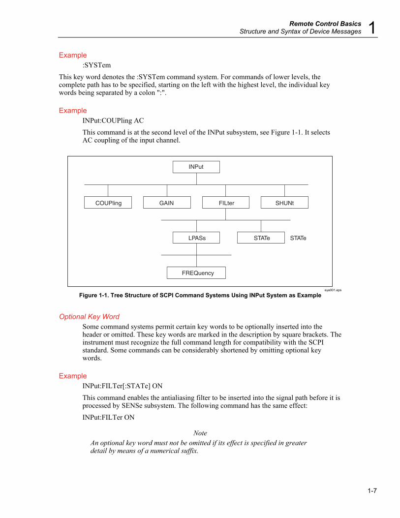


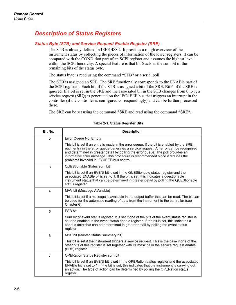
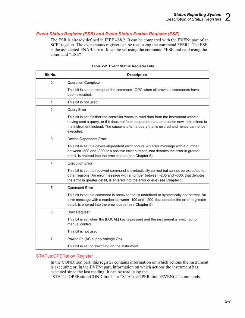


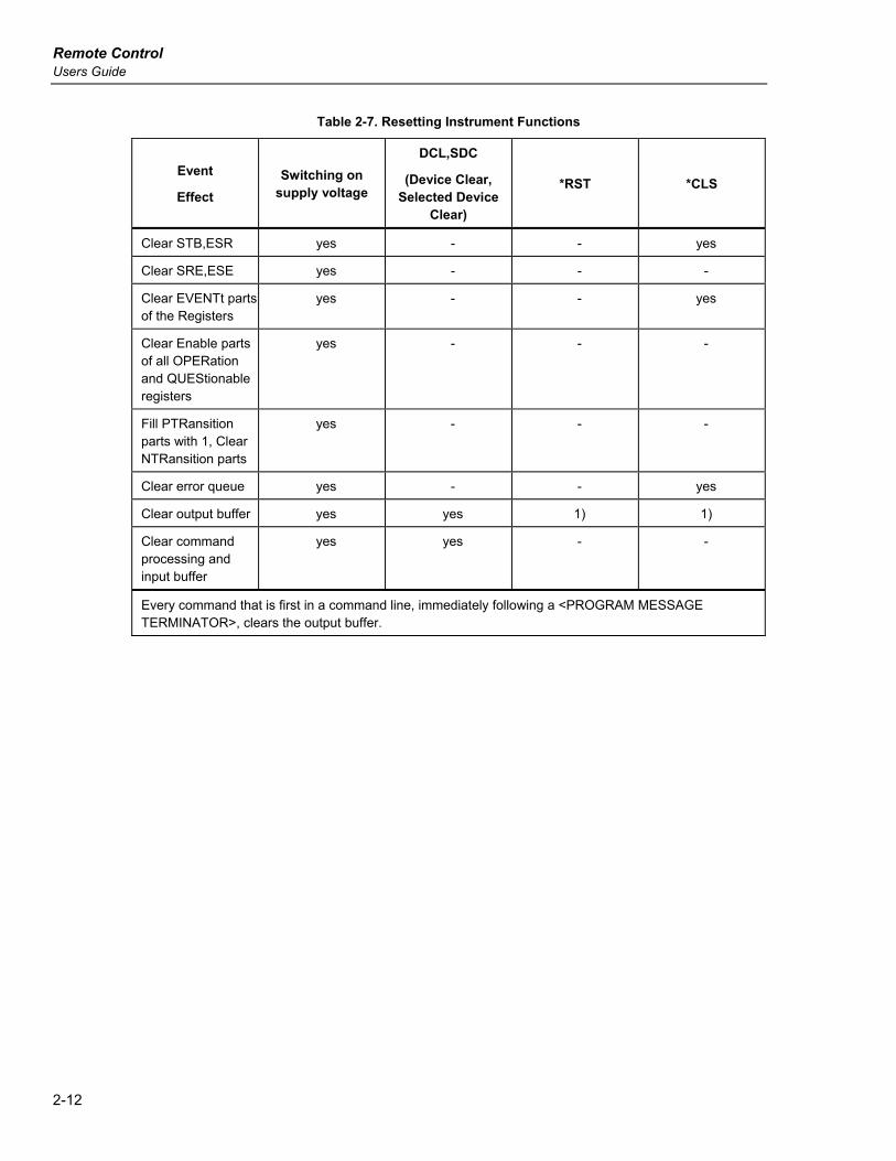


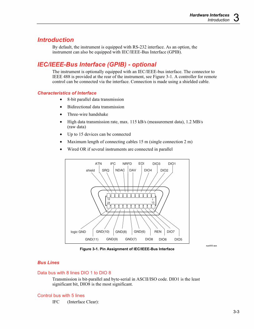


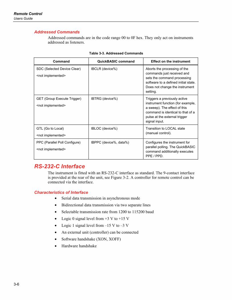
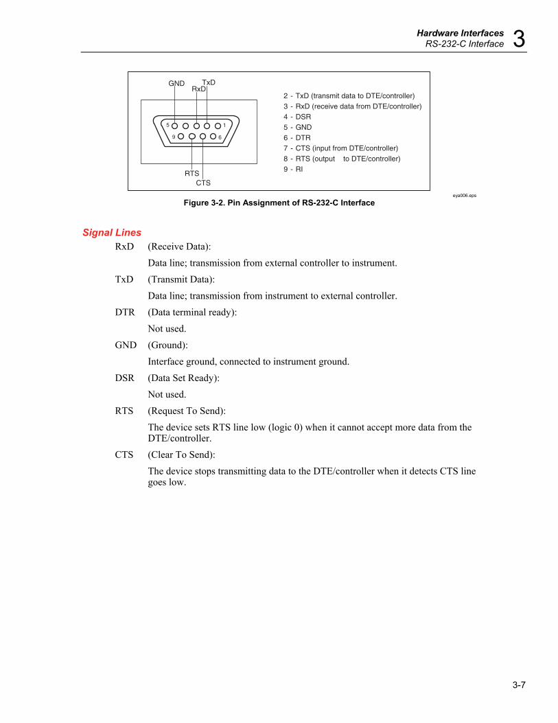


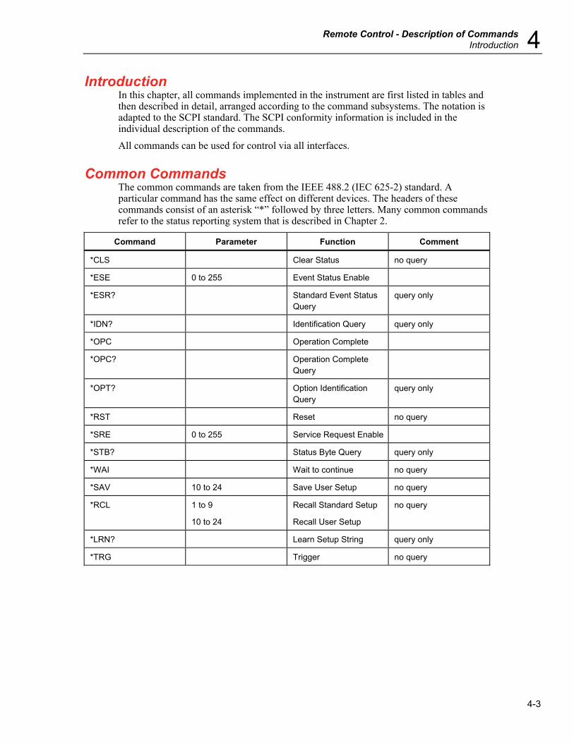

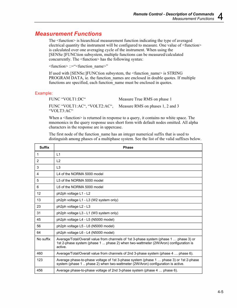


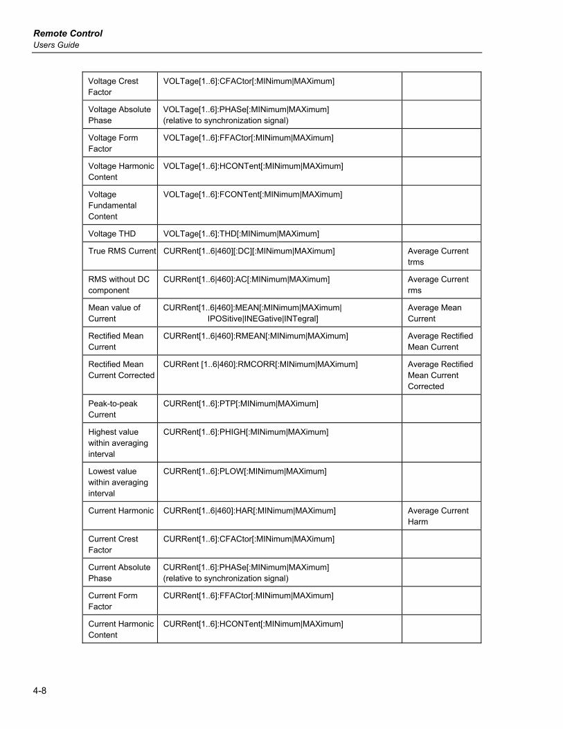


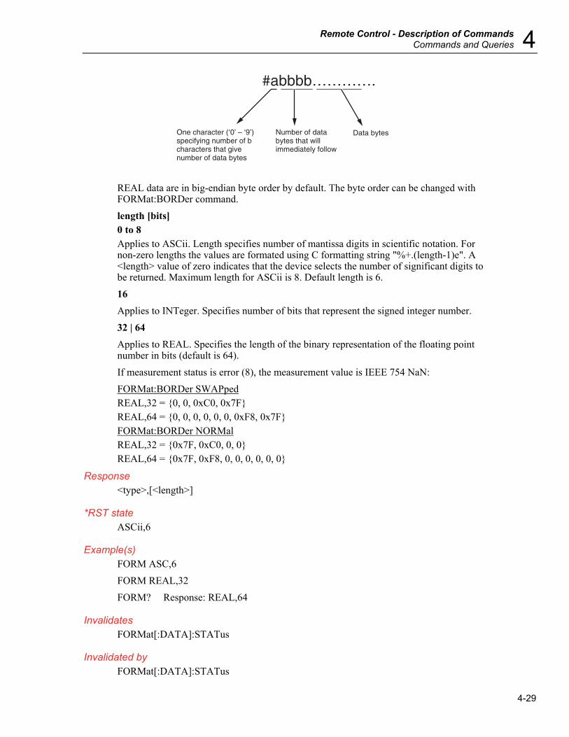


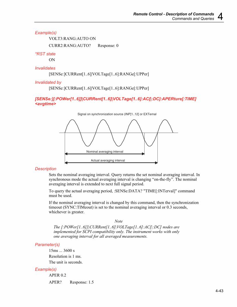


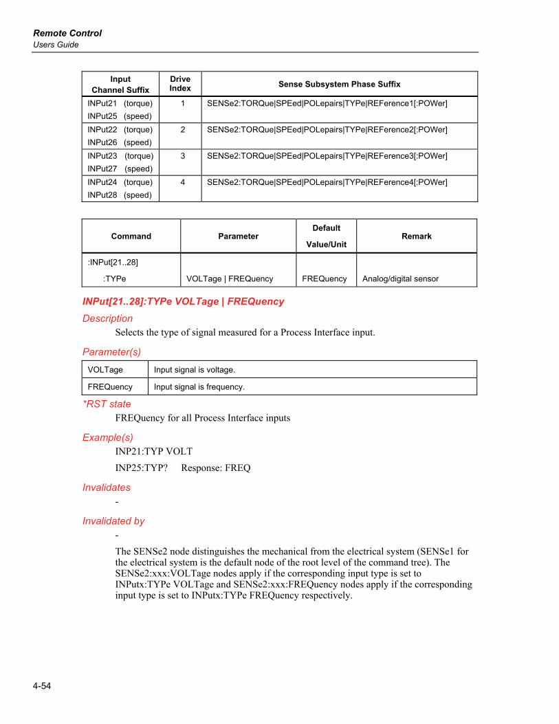


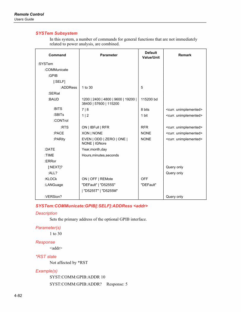


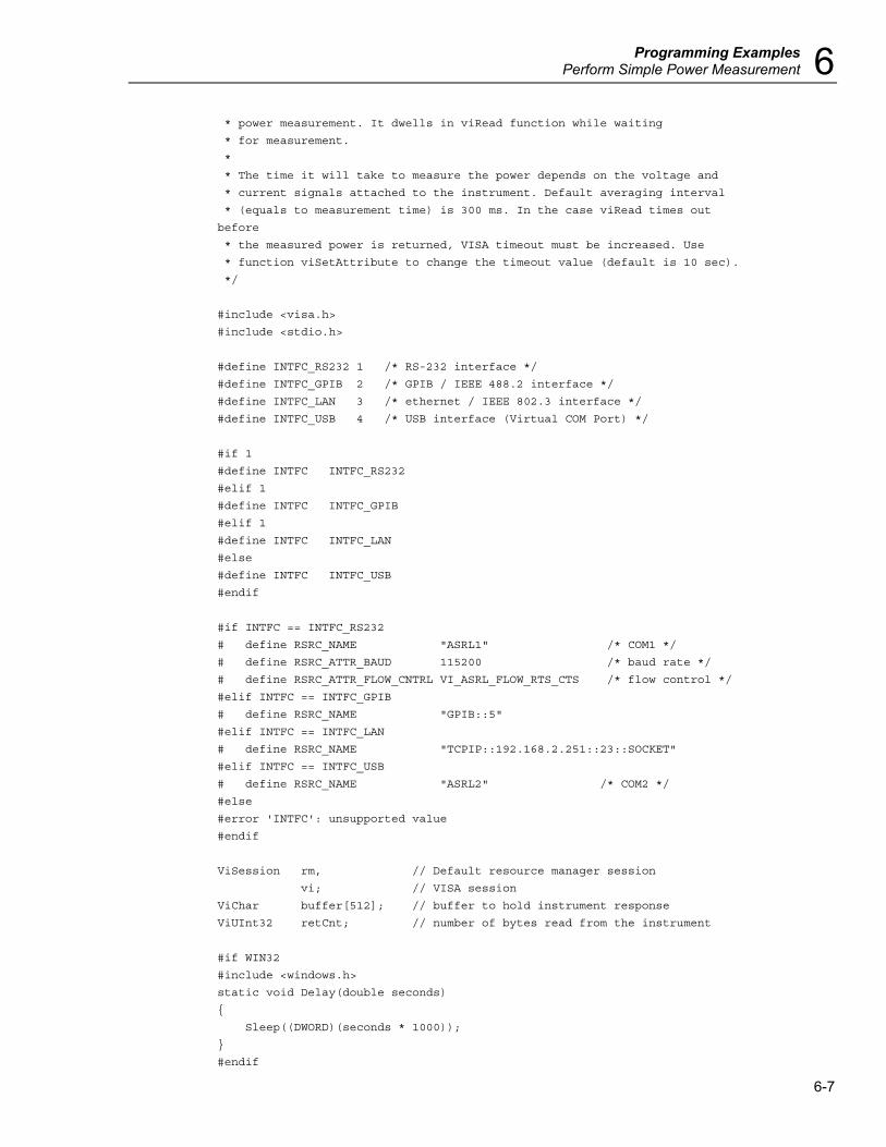

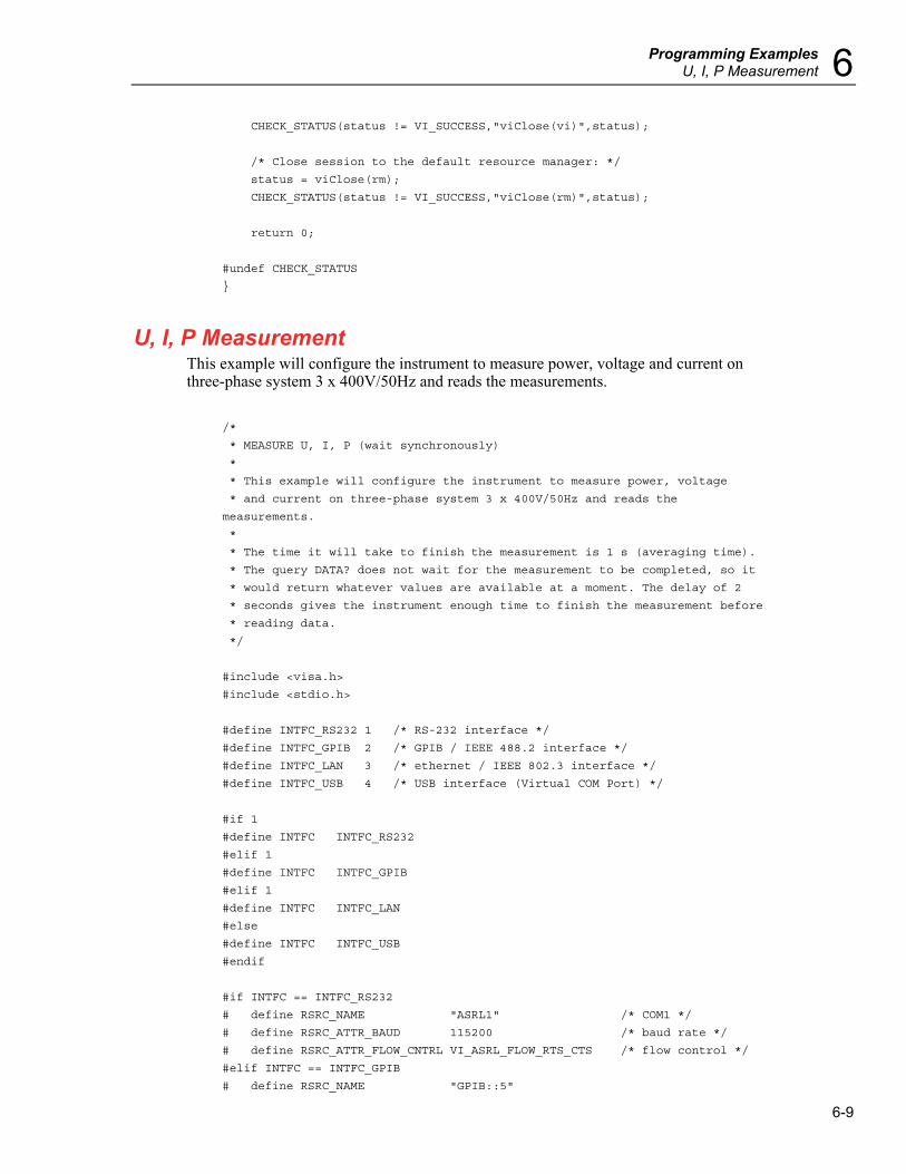


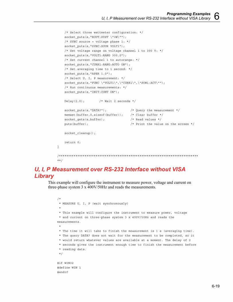
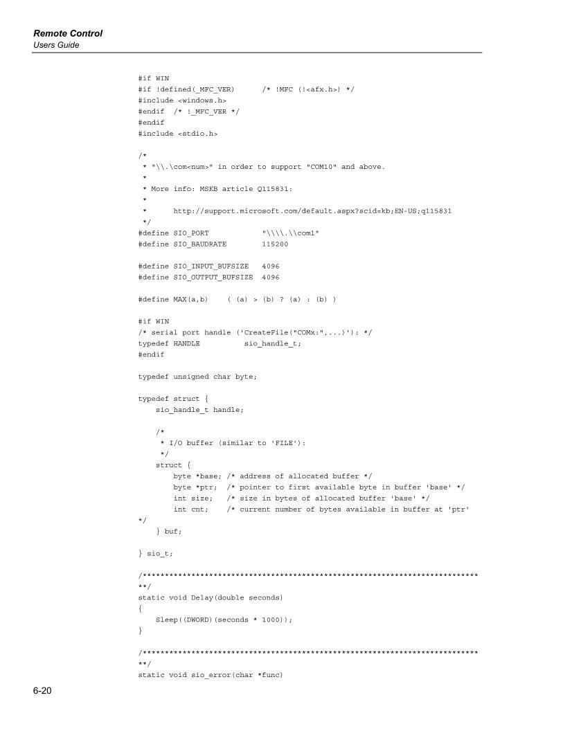


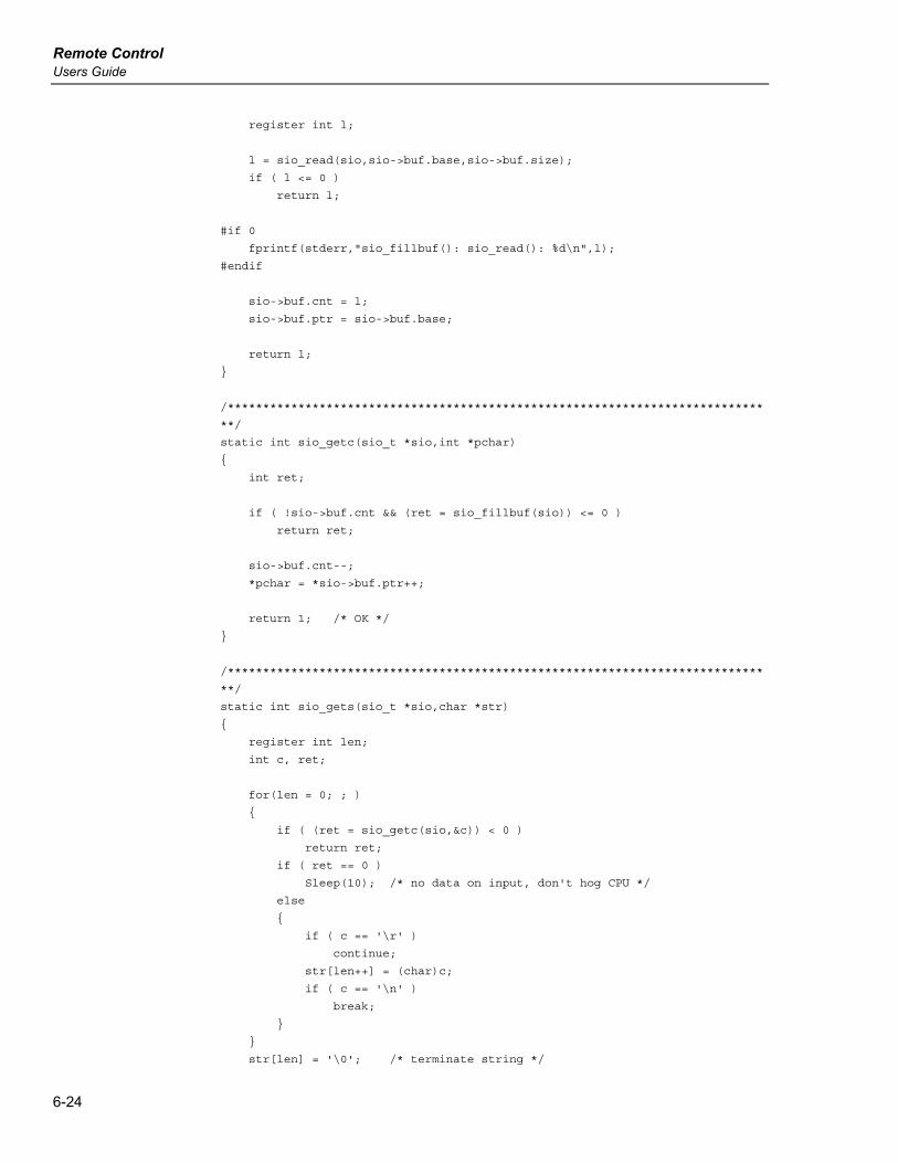
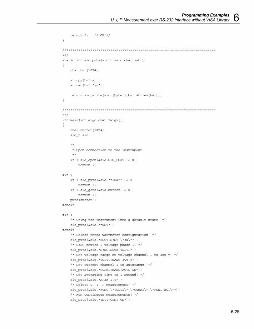


![Team : Alfa Faridh Suni [232 07 052] Alvani Wiwoho [232 07 163] Harold Harriman [232 07 088] Uray Lunar Meiviar [232 07 164]](https://static.documents.pub/doc/80x56/56649c7b5503460f9492ee5a/team-alfa-faridh-suni-232-07-052-alvani-wiwoho-232-07-163-harold-harriman.jpg)


