Worldwide Technical Support and Product Information gpelectric.comGo Power! | Dometic201-710 Redbrick Street Victoria, BC, V8T 5J3Tel: 1.866.247.6527
79498_MAN_GP_ICR_50_Rev_C
CFB
3 4 7
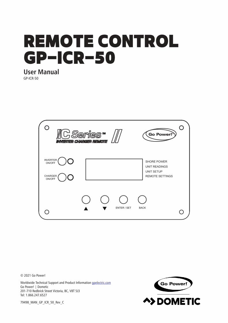
Congratulations on purchasing your Go Power! GP-ICR-50. The remote control enables you to monitor and customize your Go Power! Inverter / Charger.
This manual will aid in the process of installing and operating the Go Power! Remote Control. Please read and understand this manual before installing the Go Power! Remote Control. Please retain this manual for future reference.
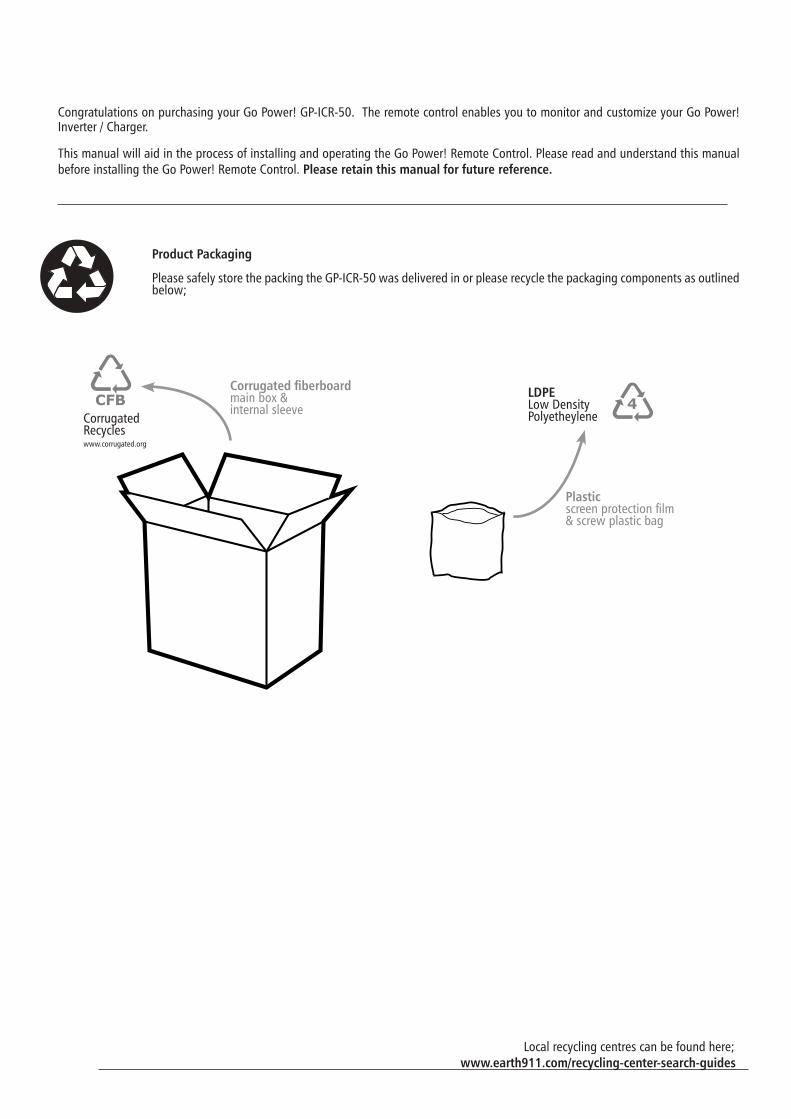
Product Packaging
Please safely store the packing the GP-ICR-50 was delivered in or please recycle the packaging components as outlined below;
Corrugated fiberboardmain box &internal sleeve
Plastic screen protection film & screw plastic bag
LDPELow Density Polyetheylene
CFB
3 4 7
CFB
3 4 7CFB
3 4 7
CorrugatedRecycleswww.corrugated.org
www.earth911.com/recycling-center-search-guidesLocal recycling centres can be found here;
gpelectric.com | [page 3]
2. GENERAL INFORMATION ..................................................................................................................................... 4
2.1 CAUTIONS .............................................................................................................42.2 DISCLAIMERS ........................................................................................................72.3 GP-ICR-50 KIT PARTS .............................................................................................7 2.3.1 PARTS CHECKLIST ....................................................................................72.4 REMOTE FEATURES ................................................................................................8
4.1 REMOTE NAVIGATION .........................................................................................164.2 SUB MENU ITEMS/OPTIONS .................................................................................184.3 SHORE POWER MAX MENU .................................................................................194.4 UNIT READINGS MENU ........................................................................................204.5 UNIT SETUP MENU ..............................................................................................214.6 REMOTE SETTINGS MENU ...................................................................................26
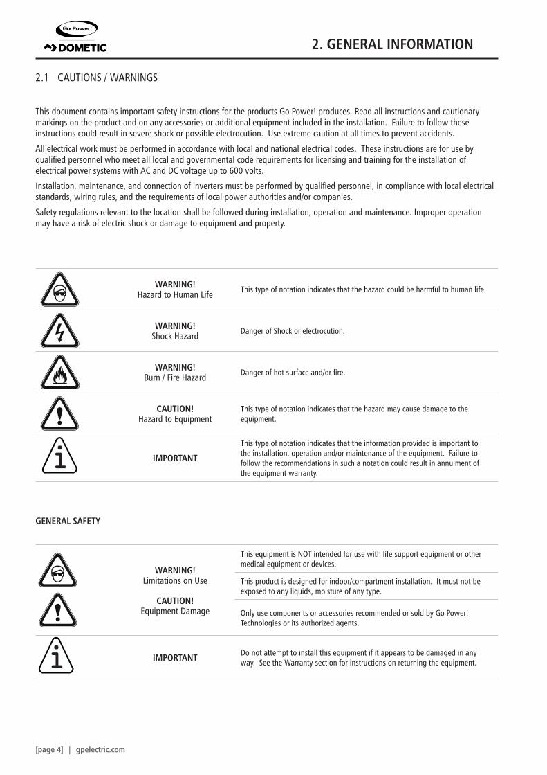
This document contains important safety instructions for the products Go Power! produces. Read all instructions and cautionary markings on the product and on any accessories or additional equipment included in the installation. Failure to follow these instructions could result in severe shock or possible electrocution. Use extreme caution at all times to prevent accidents.
All electrical work must be performed in accordance with local and national electrical codes. These instructions are for use by qualified personnel who meet all local and governmental code requirements for licensing and training for the installation of electrical power systems with AC and DC voltage up to 600 volts.
Installation, maintenance, and connection of inverters must be performed by qualified personnel, in compliance with local electrical standards, wiring rules, and the requirements of local power authorities and/or companies.
Safety regulations relevant to the location shall be followed during installation, operation and maintenance. Improper operation may have a risk of electric shock or damage to equipment and property.
GENERAL SAFETY
WARNING! Limitations on Use
CAUTION! Equipment Damage
This equipment is NOT intended for use with life support equipment or other medical equipment or devices.
This product is designed for indoor/compartment installation. It must not be exposed to any liquids, moisture of any type.
Only use components or accessories recommended or sold by Go Power! Technologies or its authorized agents.
IMPORTANT Do not attempt to install this equipment if it appears to be damaged in any way. See the Warranty section for instructions on returning the equipment.
Note
WARNING! Hazard to Human Life This type of notation indicates that the hazard could be harmful to human life.
WARNING! Shock Hazard Danger of Shock or electrocution.
WARNING! Burn / Fire Hazard Danger of hot surface and/or fire.
CAUTION! Hazard to Equipment
This type of notation indicates that the hazard may cause damage to the equipment.
IMPORTANT
This type of notation indicates that the information provided is important to the installation, operation and/or maintenance of the equipment. Failure to follow the recommendations in such a notation could result in annulment of the equipment warranty.
i
i
2. GENERAL INFORMATION
gpelectric.com | [page 5]
PERSONAL SAFETY
WARNING! Personal Injury
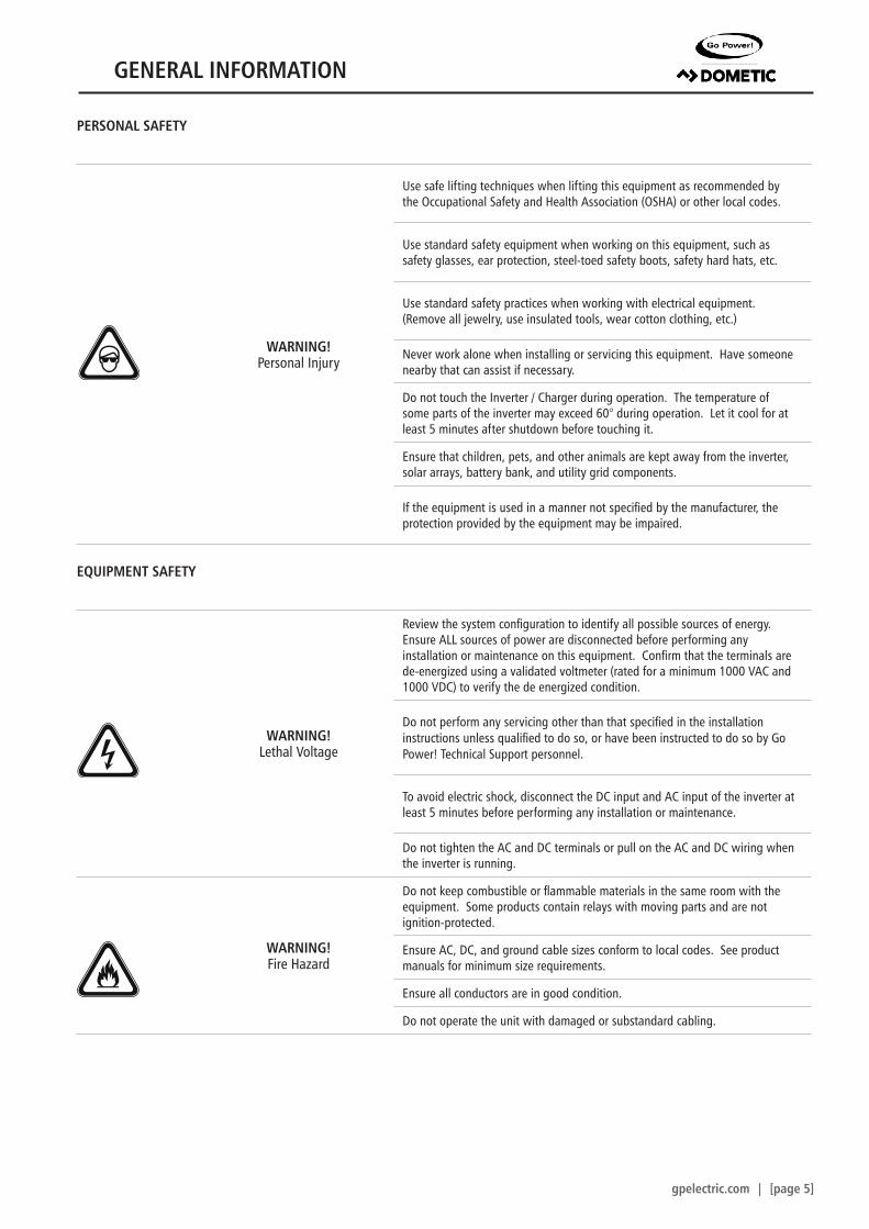
Use safe lifting techniques when lifting this equipment as recommended by the Occupational Safety and Health Association (OSHA) or other local codes.
Use standard safety equipment when working on this equipment, such as safety glasses, ear protection, steel-toed safety boots, safety hard hats, etc.
Use standard safety practices when working with electrical equipment. (Remove all jewelry, use insulated tools, wear cotton clothing, etc.)
Never work alone when installing or servicing this equipment. Have someone nearby that can assist if necessary.
Do not touch the Inverter / Charger during operation. The temperature of some parts of the inverter may exceed 60° during operation. Let it cool for at least 5 minutes after shutdown before touching it.
Ensure that children, pets, and other animals are kept away from the inverter, solar arrays, battery bank, and utility grid components.
If the equipment is used in a manner not specified by the manufacturer, the protection provided by the equipment may be impaired.
EQUIPMENT SAFETY
WARNING! Lethal Voltage
Review the system configuration to identify all possible sources of energy. Ensure ALL sources of power are disconnected before performing any installation or maintenance on this equipment. Confirm that the terminals are de-energized using a validated voltmeter (rated for a minimum 1000 VAC and 1000 VDC) to verify the de energized condition.
Do not perform any servicing other than that specified in the installation instructions unless qualified to do so, or have been instructed to do so by Go Power! Technical Support personnel.
To avoid electric shock, disconnect the DC input and AC input of the inverter at least 5 minutes before performing any installation or maintenance.
Do not tighten the AC and DC terminals or pull on the AC and DC wiring when the inverter is running.
WARNING! Fire Hazard
Do not keep combustible or flammable materials in the same room with the equipment. Some products contain relays with moving parts and are not ignition-protected.
Ensure AC, DC, and ground cable sizes conform to local codes. See product manuals for minimum size requirements.
Ensure all conductors are in good condition.
Do not operate the unit with damaged or substandard cabling.
GENERAL INFORMATION
[page 6] | gpelectric.com
CAUTION! Equipment Damage
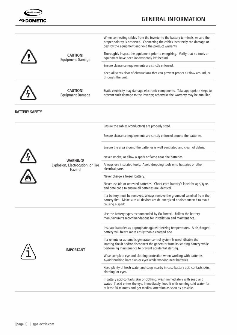
When connecting cables from the inverter to the battery terminals, ensure the proper polarity is observed. Connecting the cables incorrectly can damage or destroy the equipment and void the product warranty.
Thoroughly inspect the equipment prior to energizing. Verify that no tools or equipment have been inadvertently left behind.
Ensure clearance requirements are strictly enforced.
Keep all vents clear of obstructions that can prevent proper air flow around, or through, the unit.
CAUTION! Equipment Damage
Static electricity may damage electronic components. Take appropriate steps to prevent such damage to the inverter; otherwise the warranty may be annulled.
BATTERY SAFETY
WARNING! Explosion, Electrocution, or Fire
Hazard
Ensure the cables (conductors) are properly sized.
Ensure clearance requirements are strictly enforced around the batteries.
Ensure the area around the batteries is well ventilated and clean of debris.
Never smoke, or allow a spark or flame near, the batteries.
Always use insulated tools. Avoid dropping tools onto batteries or other electrical parts.
Never charge a frozen battery.
Never use old or untested batteries. Check each battery’s label for age, type, and date code to ensure all batteries are identical.
If a battery must be removed, always remove the grounded terminal from the battery first. Make sure all devices are de-energized or disconnected to avoid causing a spark.
IMPORTANT
Use the battery types recommended by Go Power!. Follow the battery manufacturer’s recommendations for installation and maintenance.
Insulate batteries as appropriate against freezing temperatures. A discharged battery will freeze more easily than a charged one.
If a remote or automatic generator control system is used, disable the starting circuit and/or disconnect the generator from its starting battery while performing maintenance to prevent accidental starting.
Wear complete eye and clothing protection when working with batteries. Avoid touching bare skin or eyes while working near batteries.
Keep plenty of fresh water and soap nearby in case battery acid contacts skin, clothing, or eyes.
If battery acid contacts skin or clothing, wash immediately with soap and water. If acid enters the eye, immediately flood it with running cold water for at least 20 minutes and get medical attention as soon as possible.
i
GENERAL INFORMATION
gpelectric.com | [page 7]
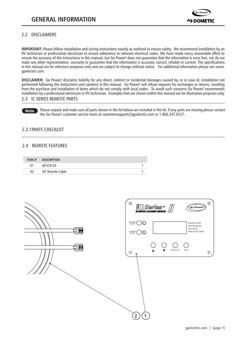
Please unpack and make sure all parts shown in the list below are included in the kit. If any parts are missing please contact the Go Power! customer service team at [email protected] or 1.866.247.6527.
2.3.1 PARTS CHECKLIST
Note
2.4 REMOTE FEATURES
2.2 DISCLAIMERS
IMPORTANT: Please follow installation and wiring instructions exactly as outlined to ensure safety. We recommend installation by an RV technician or professional electrician to ensure adherence to relevant electrical codes. We have made every reasonable effort to ensure the accuracy of the instructions in this manual, but Go Power! does not guarantee that the information is error free, nor do we make any other representation, warranty or guarantee that the information is accurate, correct, reliable or current. The specifications in this manual are for reference purposes only and are subject to change without notice. For additional information please see www.gpelectric.com.
DISCLAIMER: Go Power! disclaims liability for any direct, indirect or incidental damages caused by, or in case of, installation not performed following the instructions and cautions in this manual. Go Power! will refuse requests for exchanges or returns, resulting from the purchase and installation of items which do not comply with local codes. To avoid such concerns Go Power! recommends installation by a professional electrician or RV technician. Examples that are shown within this manual are for illustrative purposes only.2.3 IC SERIES REMOTE PARTS
ITEM # DESCRIPTION
01 GP-ICR-50 1
02 50’ Remote Cable 1
12
SHORE POWER
UNIT READINGS
INVERTERON/OFF
CHARGERON/OFF
ENTER / SET BACK
UNIT SETUPREMOTE SETTINGS
®
GENERAL INFORMATION
[page 8] | gpelectric.com
9
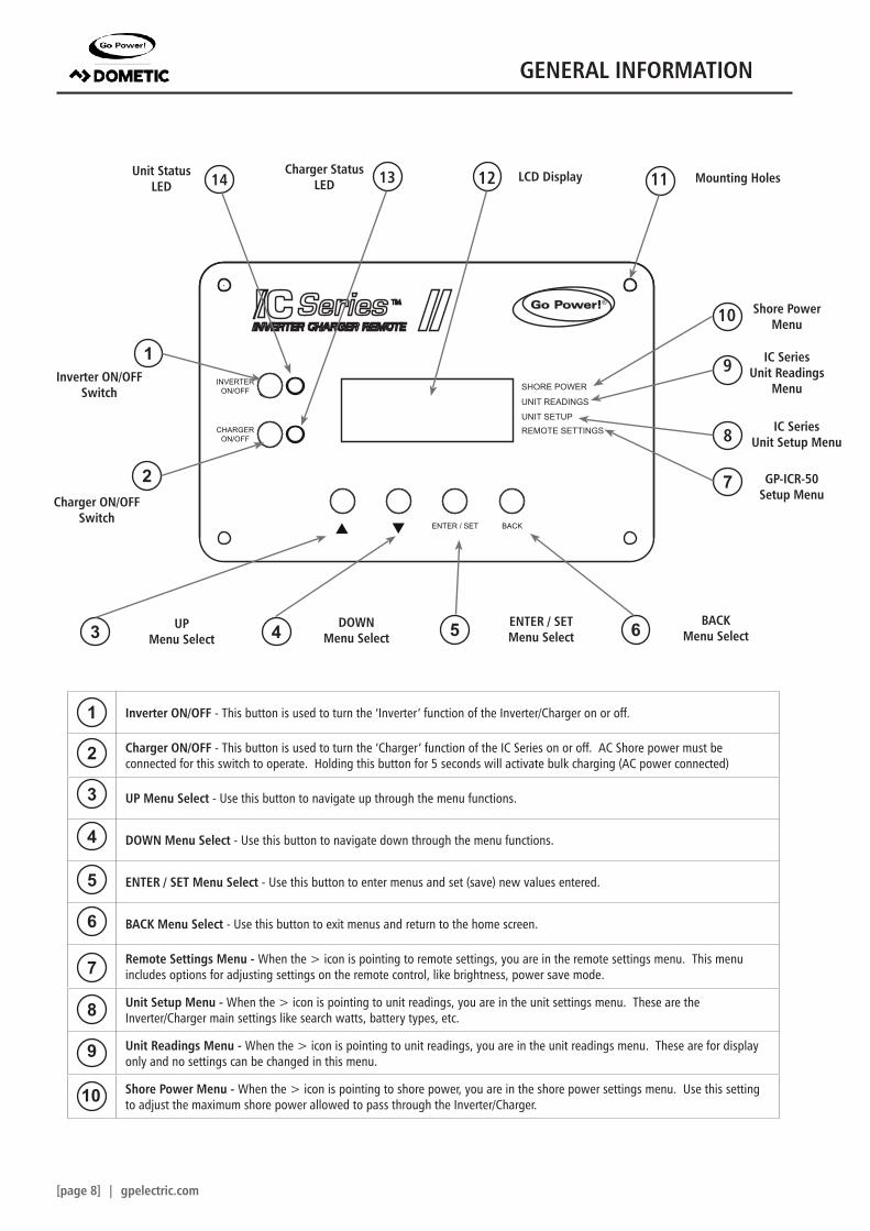
Inverter ON/OFF - This button is used to turn the ‘Inverter’ function of the Inverter/Charger on or off.
Charger ON/OFF - This button is used to turn the ‘Charger’ function of the IC Series on or off. AC Shore power must be connected for this switch to operate. Holding this button for 5 seconds will activate bulk charging (AC power connected)
UP Menu Select - Use this button to navigate up through the menu functions.
DOWN Menu Select - Use this button to navigate down through the menu functions.
ENTER / SET Menu Select - Use this button to enter menus and set (save) new values entered.
BACK Menu Select - Use this button to exit menus and return to the home screen.
Remote Settings Menu - When the > icon is pointing to remote settings, you are in the remote settings menu. This menu includes options for adjusting settings on the remote control, like brightness, power save mode.
Unit Setup Menu - When the > icon is pointing to unit readings, you are in the unit settings menu. These are the Inverter/Charger main settings like search watts, battery types, etc.
Unit Readings Menu - When the > icon is pointing to unit readings, you are in the unit readings menu. These are for display only and no settings can be changed in this menu.
Shore Power Menu - When the > icon is pointing to shore power, you are in the shore power settings menu. Use this setting to adjust the maximum shore power allowed to pass through the Inverter/Charger.
11
SHORE POWER
UNIT READINGS
INVERTERON/OFF
CHARGERON/OFF
ENTER / SET BACK
UNIT SETUPREMOTE SETTINGS
®
64
1
1
9
8
7
6
5
4
3
2
2Charger ON/OFF
Switch
Inverter ON/OFFSwitch
Mounting HolesUnit StatusLED
Charger StatusLED
IC SeriesUnit Readings
Menu
Shore PowerMenu
IC SeriesUnit Setup Menu
GP-ICR-50Setup Menu
ENTER / SETMenu Select
UPMenu Select
BACKMenu Select
DOWNMenu Select
LCD Display
8
7
14 13
10
10
12
53
GENERAL INFORMATION
gpelectric.com | [page 9]
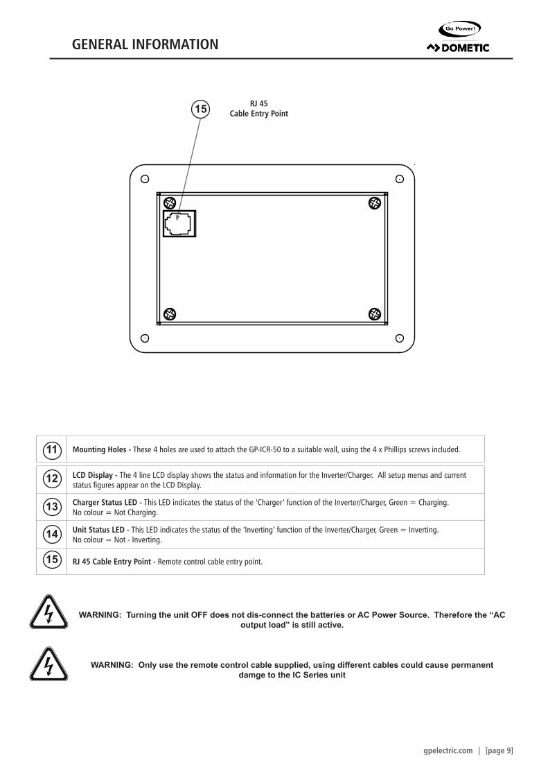
LCD Display - The 4 line LCD display shows the status and information for the Inverter/Charger. All setup menus and current status figures appear on the LCD Display.
Charger Status LED - This LED indicates the status of the ‘Charger’ function of the Inverter/Charger, Green = Charging. No colour = Not Charging.
Unit Status LED - This LED indicates the status of the ‘Inverting’ function of the Inverter/Charger, Green = Inverting. No colour = Not - Inverting.
RJ 45 Cable Entry Point - Remote control cable entry point.
Mounting Holes - These 4 holes are used to attach the GP-ICR-50 to a suitable wall, using the 4 x Phillips screws included.
15 RJ 45Cable Entry Point
WARNING: Turning the unit OFF does not dis-connect the batteries or AC Power Source. Therefore the “AC output load” is still active.
WARNING: Only use the remote control cable supplied, using different cables could cause permanent damge to the IC Series unit
11
12
13
14
15
SHORE POWER
UNIT READINGS
INVERTERON/OFF
CHARGERON/OFF
ENTER / SET BACK
UNIT SETUPREMOTE SETTINGS
®
2.7”
(69m
m)
1.22” (31mm)
3.9”
(98m
m)
3.3”
(83m
m)
5.2” (133mm)5.9” (149mm)
4.7” (120mm)
GENERAL INFORMATION
[page 10] | gpelectric.com
Cable to IC Series
FM80
30 Amp Breaker
FuseBlock
Battery Bank
MC4 Connector
RefrigeratorVent Cover
100W or 160WSolar Panel
Mate 2
Legend
Remote
10 Ft Extension Cable 10AWG (Included)
25 Ft Cable 10AWG (Included)
For this system we recommend a minimum of 6 batteries / 600 Amp Hour
Battery Bank
RV Console
Area
Solar Controller
Cable to Battery Bank
Battery Bank
Solar Panels
Cables FromSolar Charge Controller
Internal View
GP-IC-Remote
Cable to Inverter
RefrigeratorVent Cover
100W or 160WSolar Panel
SolarController
FuseBlock
Inverter
InverterRemote
ACLoads
ACPanel
TransferSwitch
FuseBlock
Converter / Charger
Shore Power / Generator
AC Power OUTPUT - to RV appliances
IC SeriesInverter/ChargerIC SeriesInverter/Charger
Cables to/fromBattery Bank
AC Power INPUT- from Shore Power/Generator(Fuses/Breakers not shown)
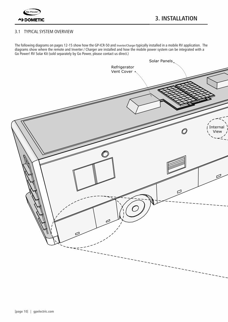
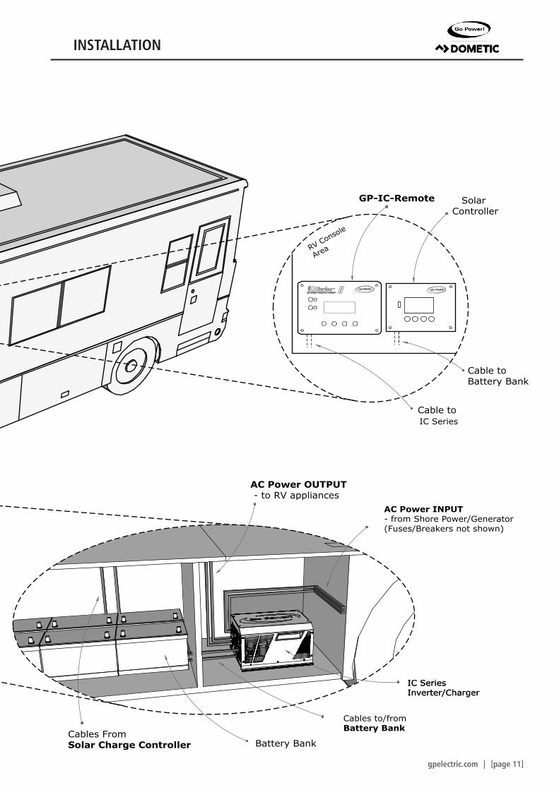
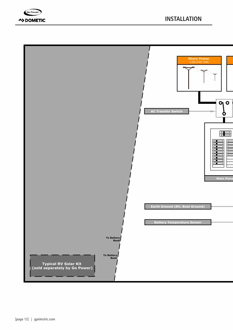
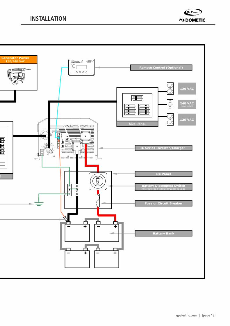
3. INSTALLATION3.1 TYPICAL SYSTEM OVERVIEW
The following diagrams on pages 12-15 show how the GP-ICR-50 and Inverter/Charger typically installed in a mobile RV application. The diagrams show where the remote and Inverter / Charger are installed and how the mobile power system can be integrated with a Go Power! RV Solar Kit (sold separately by Go Power, please contact us direct.)
3. INSTALLATION
gpelectric.com | [page 11]
Cable to IC Series
FM80
30 Amp Breaker
FuseBlock
Battery Bank
MC4 Connector
RefrigeratorVent Cover
100W or 160WSolar Panel
Mate 2
Legend
Remote
10 Ft Extension Cable 10AWG (Included)
25 Ft Cable 10AWG (Included)
For this system we recommend a minimum of 6 batteries / 600 Amp Hour
Battery Bank
RV Console
Area
Solar Controller
Cable to Battery Bank
Battery Bank
Solar Panels
Cables FromSolar Charge Controller
Internal View
GP-IC-Remote
Cable to Inverter
RefrigeratorVent Cover
100W or 160WSolar Panel
SolarController
FuseBlock
Inverter
InverterRemote
ACLoads
ACPanel
TransferSwitch
FuseBlock
Converter / Charger
Shore Power / Generator
AC Power OUTPUT - to RV appliances
IC SeriesInverter/ChargerIC SeriesInverter/Charger
Cables to/fromBattery Bank
AC Power INPUT- from Shore Power/Generator(Fuses/Breakers not shown)
INSTALLATION
[page 12] | gpelectric.com
ON
OFF
Shore Power 120/240 VAC
Generator Power120/240 VAC
Main Panel
Sub Panel
120 VAC
240 VAC(cabin install)
Remote Control (Optional)
AC Transfer Switch
Solar Panel Solar Panel
Solar Charge Controller
RefrigeratorVent Cover
or Cable Entry Plate
Fuse
Battery Temperature Sensor
Typical RV Solar Kit (sold separately by Go Power)
Battery Disconnect Switch(not required if circuit breaker is used)
Battery Bank
Fuse or Circuit Breaker
IC Series Inverter/Charger
To BatteryBank
To BatteryBank
DC Panel
Earth Ground (RV, Boat Ground)
120 VAC
INSTALLATION
gpelectric.com | [page 13]
ON
OFF
Shore Power 120/240 VAC
Generator Power120/240 VAC
Main Panel
Sub Panel
120 VAC
240 VAC(cabin install)
Remote Control (Optional)
AC Transfer Switch
Solar Panel Solar Panel
Solar Charge Controller
RefrigeratorVent Cover
or Cable Entry Plate
Fuse
Battery Temperature Sensor
Typical RV Solar Kit (sold separately by Go Power)
Battery Disconnect Switch(not required if circuit breaker is used)
Battery Bank
Fuse or Circuit Breaker
IC Series Inverter/Charger
To BatteryBank
To BatteryBank
DC Panel
Earth Ground (RV, Boat Ground)
120 VAC
INSTALLATION
[page 14] | gpelectric.com
a. Screwdriver (Phillips)b. Keyhole sawc. Pencil or markerd. Electric hand drill and drill bitse. Zip ties
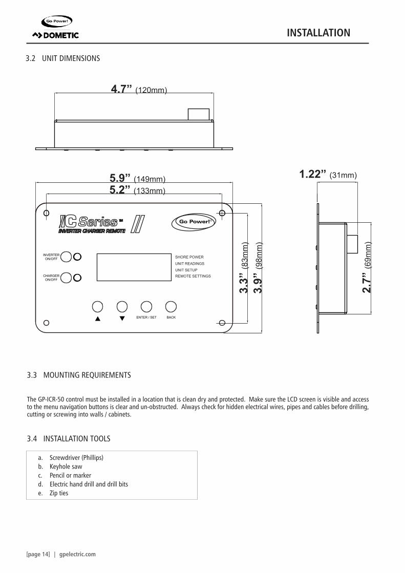
3.2 UNIT DIMENSIONS
3.3 MOUNTING REQUIREMENTS
The GP-ICR-50 control must be installed in a location that is clean dry and protected. Make sure the LCD screen is visible and access to the menu navigation buttons is clear and un-obstructed. Always check for hidden electrical wires, pipes and cables before drilling, cutting or screwing into walls / cabinets.
3.4 INSTALLATION TOOLS
SHORE POWER
UNIT READINGS
INVERTERON/OFF
CHARGERON/OFF
ENTER / SET BACK
UNIT SETUPREMOTE SETTINGS
®
2.7”
(69m
m)
1.22” (31mm)
3.9”
(98m
m)
3.3”
(83m
m)
5.2” (133mm)5.9” (149mm)
4.7” (120mm)
INSTALLATION
gpelectric.com | [page 15]
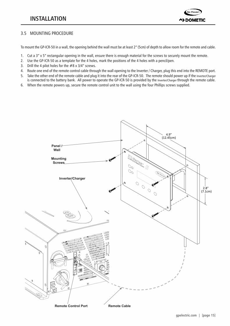
3.5 MOUNTING PROCEDURE
To mount the GP-ICR-50 in a wall, the opening behind the wall must be at least 2” (5cm) of depth to allow room for the remote and cable.
1. Cut a 3” x 5” rectangular opening in the wall, ensure there is enough material for the screws to securely mount the remote.2. Use the GP-ICR-50 as a template for the 4 holes, mark the positions of the 4 holes with a pencil/pen.3. Drill the 4 pilot holes for the #8 x 3/4” screws.4. Route one end of the remote control cable through the wall opening to the Inverter / Charger, plug this end into the REMOTE port.5. Take the other end of the remote cable and plug it into the rear of the GP-ICR-50. The remote should power up if the Inverter/Charger
is connected to the battery bank. All power to operate the GP-ICR-50 is provided by the Inverter/Charger through the remote cable.6. When the remote powers up, secure the remote control unit to the wall using the four Phillips screws supplied.
Remote Control Port Remote Cable
Inverter/Charger
Panel / Wall
Mounting Screws
(304mm)12”
(51mm)2”
(124mm)4.9” (124mm)4.9”
(346mm)13.6”
(7mm) (13mm).28”
(321mm)12.6”
.51”
(205mm)8.1”
(349mm)13.7”
(378mm)14.9”
REMOTE
BATTERYTEMP
ON/OFF
STATUS
INV. / CHR.MODE
AC INPUT
INV. ACOUTPUT
NEG -
POS +
BATTERYTEMP
REMOTE
CAUTION:• TO PREVENT FIRE, DO NOT COVER OR OBSTRUCT VENTILATION OPENINGS. DO NOT MOUNT IN ZERO-CLEARANCE
COMPARTMENT. OVERHEATING MAY RESULT. • RISK OF ELECTRIC SHOCK, DO NOT REMOVE COVER, NO USER SERVICEABLE PARTS INSIDE. REFER SERVICING TO QUALIFIED SERVICE PERSONNEL. • TO REDUCE RISK OF
ELECTRIC SHOCK, DO NOT EXPOSE TO RAIN OR SPRAY. • BATTERY POLARITY MUST BE CORRECT OR DAMAGE WILL RESULT. • PROVIDED WITH INTEGRAL PROTECTION AGAINST OVERLOADS. • CHARGE ONLY LEAD ACID TYPE
RECHARGEABLE BATTERIES, EACH 6 or 12 CELLS IN THE BATTERY.
MISE EN GARDE:• POUR PRÉVENIR LES RISQUES D’INCENDIE, NE PAS COUVRIR NI OBSTRUER LES OUVERTURES D’AÉRATION. NE
PAS MONTER LE PRODUIT DANS UN COMPARTIMENT SANS AUCUN DÉGAGEMENT. RISQUE DE SURCHAUFFE. • RISQUE DE DÉCHARGE ÉLECTRIQUE, NE PAS RETIRER LE COUVERCLE, NE CONTIENT AUCUNE PIÈCE SUSCEPTIBLE
D’ÊTRE RÉPARÉE PAR L’UTILISATEUR. CONFIEZ L’ENTRETIEN À DU PERSONNEL QUALIFIÉ. • POUR RÉDUIRE LES RISQUES DE DÉCHARGE ÉLECTRIQUE, NE PAS L’EXPOSER À LA PLUIE OU À LA PULVÉRISATION. • L’ORIENTATION
DE LA POLARITÉ DES PILES DOIT ÊTRE CORRECTE, AU RISQUE D’ENDOMMAG ER LE PRODUIT. • FOURNI AVEC UNE PROTECTION INTÉGRALE CONTRE LA SURCHARGE. • NE CHARGER QUE DES PILES AU PLOMB RECHARGEABLES
CONTENANT CHACUNE 6 ou 12 CELLULES.
WARNING: • THIS EQUIPMENT EMPLOYS COMPONENTS THAT TEND TO PRODUCE ARCS OR SPARKS. TO PREVENT FIRE OR
EXPLOSION, DO NOT INSTALL IN COMPARTMENTS CONTAINING BATTERIES OR FLAMMABLE MATERIALS. • RISK OF ELECTRIC SHOCK. USE ONLY THE GROUND-FAULT CIRCUIT-INTERRUPTER RECEPTACLE OR CIRCUIT
BREAKER SPECIFIED IN THE INSTALLATION AND OPERATING INSTRUCTIONS SUPPLIED WITH THIS UNIT. OTHER TYPES MAY FAIL TO OPERATE PROPERLY WHEN CONNECTED TO THIS UNIT. • RISK OF ELECTRIC SHOCK,
HEATSINKS ARE NOT BONDED TO GROUND, TEST BEFORE TOUCHING. • INTENDED FOR CONTINUOUS DUTY.
AVERTISSEMENT:• CET ÉQUIPEMENT EMPLOIE DES COMPOSANTS POUVANT PROVOQUER DES ARCS ÉLECTRIQUES OU DES
ÉTINCELLES. POUR PRÉVENIR LES RISQUES D’INCENDIE OU D’EXPLOSION, NE PAS INSTALLER LE PRODUIT DANS UN COMPARTIMENT CONTENANT DES PILES OU DES MATÉRIAUX INFLAMMABLES. • RISQUE DE
DÉCHARGE ÉLECTRIQUE. UTILISER UNIQUEMENT LE RÉCEPTACLE D’INTERRUPTEUR DE CIRCUIT DE MISE À LA MASSE OU LE COUPE-CIRCUIT INDIQUÉS DANS LE MANUEL D’INSTALLATION ET D’UTILISATION FOURNI AVEC CE
PRODUIT. LES AUTRES TYPES PEUVENT NE PAS FONCTIONNER CORRECTEMENT LORSQU’ILS SONT CONNECTÉS À CE PRODUIT. • RISQUE DE DÉCHARGE ÉLECTRIQUE, PUITS THERMIQUES NON MIS À LA TERRE,
TESTER AVANT DE TOUCHER. • PRÉVU POUR UNE UTILISATION CONTINUE.
DANGER:• TO REDUCE THE RISK OF EXPLOSION - DO NOT INSTALL IN MACHINERY SPACE OR AREA IN WHICH IGNITION
- PROTECTED EQUIPMENT IS REQUIRED.• POUR RÉDUIRE LE RISQUE D’EXPLOSION, NE PAS INSTALLER LE PRODUIT DANS UN COMPARTIMENT
MACHINE OU UNE ZONE CONTENANT UN ALLUMAGE — L’ÉQUIPEMENT PROTÉGÉ EST EXIGÉ
CB2INPUT
50A
CB1INPUT
50A
REMOTE
BATTERYTEMP
ON/OFF
STATUS
INV. / CHR.MODE
AC INPUT
INV. ACOUTPUT
NEG -
POS +
CAUTION:• TO PREVENT FIRE, DO NOT COVER OR OBSTRUCT VENTILATION OPENINGS. DO NOT MOUNT IN ZERO-CLEARANCE
COMPARTMENT. OVERHEATING MAY RESULT. • RISK OF ELECTRIC SHOCK, DO NOT REMOVE COVER, NO USER SERVICEABLE PARTS INSIDE. REFER SERVICING TO QUALIFIED SERVICE PERSONNEL. • TO REDUCE RISK OF
ELECTRIC SHOCK, DO NOT EXPOSE TO RAIN OR SPRAY. • BATTERY POLARITY MUST BE CORRECT OR DAMAGE WILL RESULT. • PROVIDED WITH INTEGRAL PROTECTION AGAINST OVERLOADS. • CHARGE ONLY LEAD ACID TYPE
RECHARGEABLE BATTERIES, EACH 6 or 12 CELLS IN THE BATTERY.
MISE EN GARDE:• POUR PRÉVENIR LES RISQUES D’INCENDIE, NE PAS COUVRIR NI OBSTRUER LES OUVERTURES D’AÉRATION. NE
PAS MONTER LE PRODUIT DANS UN COMPARTIMENT SANS AUCUN DÉGAGEMENT. RISQUE DE SURCHAUFFE. • RISQUE DE DÉCHARGE ÉLECTRIQUE, NE PAS RETIRER LE COUVERCLE, NE CONTIENT AUCUNE PIÈCE SUSCEPTIBLE
D’ÊTRE RÉPARÉE PAR L’UTILISATEUR. CONFIEZ L’ENTRETIEN À DU PERSONNEL QUALIFIÉ. • POUR RÉDUIRE LES RISQUES DE DÉCHARGE ÉLECTRIQUE, NE PAS L’EXPOSER À LA PLUIE OU À LA PULVÉRISATION. • L’ORIENTATION
DE LA POLARITÉ DES PILES DOIT ÊTRE CORRECTE, AU RISQUE D’ENDOMMAG ER LE PRODUIT. • FOURNI AVEC UNE PROTECTION INTÉGRALE CONTRE LA SURCHARGE. • NE CHARGER QUE DES PILES AU PLOMB RECHARGEABLES
CONTENANT CHACUNE 6 ou 12 CELLULES.
WARNING: • THIS EQUIPMENT EMPLOYS COMPONENTS THAT TEND TO PRODUCE ARCS OR SPARKS. TO PREVENT FIRE OR
EXPLOSION, DO NOT INSTALL IN COMPARTMENTS CONTAINING BATTERIES OR FLAMMABLE MATERIALS. • RISK OF ELECTRIC SHOCK. USE ONLY THE GROUND-FAULT CIRCUIT-INTERRUPTER RECEPTACLE OR CIRCUIT
BREAKER SPECIFIED IN THE INSTALLATION AND OPERATING INSTRUCTIONS SUPPLIED WITH THIS UNIT. OTHER TYPES MAY FAIL TO OPERATE PROPERLY WHEN CONNECTED TO THIS UNIT. • RISK OF ELECTRIC SHOCK,
HEATSINKS ARE NOT BONDED TO GROUND, TEST BEFORE TOUCHING. • INTENDED FOR CONTINUOUS DUTY.
AVERTISSEMENT:• CET ÉQUIPEMENT EMPLOIE DES COMPOSANTS POUVANT PROVOQUER DES ARCS ÉLECTRIQUES OU DES
ÉTINCELLES. POUR PRÉVENIR LES RISQUES D’INCENDIE OU D’EXPLOSION, NE PAS INSTALLER LE PRODUIT DANS UN COMPARTIMENT CONTENANT DES PILES OU DES MATÉRIAUX INFLAMMABLES. • RISQUE DE
DÉCHARGE ÉLECTRIQUE. UTILISER UNIQUEMENT LE RÉCEPTACLE D’INTERRUPTEUR DE CIRCUIT DE MISE À LA MASSE OU LE COUPE-CIRCUIT INDIQUÉS DANS LE MANUEL D’INSTALLATION ET D’UTILISATION FOURNI AVEC CE
PRODUIT. LES AUTRES TYPES PEUVENT NE PAS FONCTIONNER CORRECTEMENT LORSQU’ILS SONT CONNECTÉS À CE PRODUIT. • RISQUE DE DÉCHARGE ÉLECTRIQUE, PUITS THERMIQUES NON MIS À LA TERRE,
TESTER AVANT DE TOUCHER. • PRÉVU POUR UNE UTILISATION CONTINUE.
DANGER:• TO REDUCE THE RISK OF EXPLOSION - DO NOT INSTALL IN MACHINERY SPACE OR AREA IN WHICH IGNITION
- PROTECTED EQUIPMENT IS REQUIRED.• POUR RÉDUIRE LE RISQUE D’EXPLOSION, NE PAS INSTALLER LE PRODUIT DANS UN COMPARTIMENT
MACHINE OU UNE ZONE CONTENANT UN ALLUMAGE — L’ÉQUIPEMENT PROTÉGÉ EST EXIGÉ
CB2INPUT
50A
CB1INPUT
50A
CAUTION:• TO PREVENT FIRE, DO NOT COVER OR OBSTRUCT VENTILATION OPENINGS. DO NOT MOUNT IN ZERO-CLEARANCE
COMPARTMENT. OVERHEATING MAY RESULT. • RISK OF ELECTRIC SHOCK, DO NOT REMOVE COVER, NO USER SERVICEABLE PARTS INSIDE. REFER SERVICING TO QUALIFIED SERVICE PERSONNEL. • TO REDUCE RISK OF
ELECTRIC SHOCK, DO NOT EXPOSE TO RAIN OR SPRAY. • BATTERY POLARITY MUST BE CORRECT OR DAMAGE WILL RESULT. • PROVIDED WITH INTEGRAL PROTECTION AGAINST OVERLOADS. • CHARGE ONLY LEAD ACID TYPE
RECHARGEABLE BATTERIES, EACH 6 or 12 CELLS IN THE BATTERY.
MISE EN GARDE:• POUR PRÉVENIR LES RISQUES D’INCENDIE, NE PAS COUVRIR NI OBSTRUER LES OUVERTURES D’AÉRATION. NE
PAS MONTER LE PRODUIT DANS UN COMPARTIMENT SANS AUCUN DÉGAGEMENT. RISQUE DE SURCHAUFFE. • RISQUE DE DÉCHARGE ÉLECTRIQUE, NE PAS RETIRER LE COUVERCLE, NE CONTIENT AUCUNE PIÈCE SUSCEPTIBLE
D’ÊTRE RÉPARÉE PAR L’UTILISATEUR. CONFIEZ L’ENTRETIEN À DU PERSONNEL QUALIFIÉ. • POUR RÉDUIRE LES RISQUES DE DÉCHARGE ÉLECTRIQUE, NE PAS L’EXPOSER À LA PLUIE OU À LA PULVÉRISATION. • L’ORIENTATION
DE LA POLARITÉ DES PILES DOIT ÊTRE CORRECTE, AU RISQUE D’ENDOMMAG ER LE PRODUIT. • FOURNI AVEC UNE PROTECTION INTÉGRALE CONTRE LA SURCHARGE. • NE CHARGER QUE DES PILES AU PLOMB RECHARGEABLES
CONTENANT CHACUNE 6 ou 12 CELLULES.
WARNING: • THIS EQUIPMENT EMPLOYS COMPONENTS THAT TEND TO PRODUCE ARCS OR SPARKS. TO PREVENT FIRE OR
EXPLOSION, DO NOT INSTALL IN COMPARTMENTS CONTAINING BATTERIES OR FLAMMABLE MATERIALS. • RISK OF ELECTRIC SHOCK. USE ONLY THE GROUND-FAULT CIRCUIT-INTERRUPTER RECEPTACLE OR CIRCUIT
BREAKER SPECIFIED IN THE INSTALLATION AND OPERATING INSTRUCTIONS SUPPLIED WITH THIS UNIT. OTHER TYPES MAY FAIL TO OPERATE PROPERLY WHEN CONNECTED TO THIS UNIT. • RISK OF ELECTRIC SHOCK,
HEATSINKS ARE NOT BONDED TO GROUND, TEST BEFORE TOUCHING. • INTENDED FOR CONTINUOUS DUTY.
AVERTISSEMENT:• CET ÉQUIPEMENT EMPLOIE DES COMPOSANTS POUVANT PROVOQUER DES ARCS ÉLECTRIQUES OU DES
ÉTINCELLES. POUR PRÉVENIR LES RISQUES D’INCENDIE OU D’EXPLOSION, NE PAS INSTALLER LE PRODUIT DANS UN COMPARTIMENT CONTENANT DES PILES OU DES MATÉRIAUX INFLAMMABLES. • RISQUE DE
DÉCHARGE ÉLECTRIQUE. UTILISER UNIQUEMENT LE RÉCEPTACLE D’INTERRUPTEUR DE CIRCUIT DE MISE À LA MASSE OU LE COUPE-CIRCUIT INDIQUÉS DANS LE MANUEL D’INSTALLATION ET D’UTILISATION FOURNI AVEC CE
PRODUIT. LES AUTRES TYPES PEUVENT NE PAS FONCTIONNER CORRECTEMENT LORSQU’ILS SONT CONNECTÉS À CE PRODUIT. • RISQUE DE DÉCHARGE ÉLECTRIQUE, PUITS THERMIQUES NON MIS À LA TERRE,
TESTER AVANT DE TOUCHER. • PRÉVU POUR UNE UTILISATION CONTINUE.
DANGER:• TO REDUCE THE RISK OF EXPLOSION - DO NOT INSTALL IN MACHINERY SPACE OR AREA IN WHICH IGNITION - PROTECTED EQUIPMENT IS REQUIRED.
• POUR RÉDUIRE LE RISQUE D’EXPLOSION, NE PAS INSTALLER LE PRODUIT DANS UN COMPARTIMENT MACHINE OU UNE ZONE CONTENANT UN ALLUMAGE — L’ÉQUIPEMENT PROTÉGÉ EST EXIGÉ
Maximum AC Input Current: 50 AAC● Maximum Power: 12000 VA
● DC Output Range: 8.5 to 16.5VDC
Grid Input Frequency: 60Hz● Generator Input Frequency Range: 50 to 70Hz●
Power Factor: >0.98
Conforms to UL 458 (6th Ed.) and UL STD 1741 (2nd. Ed.) Certified to CSA C22.2 No. 107.1-01
5GW2
MQ7275MARINE POWER INVERTER
5DA7
E198012POWER INVERTER E483757
4.9"(12.45cm)
2.8"(7.1cm)
INSTALLATION
[page 16] | gpelectric.com
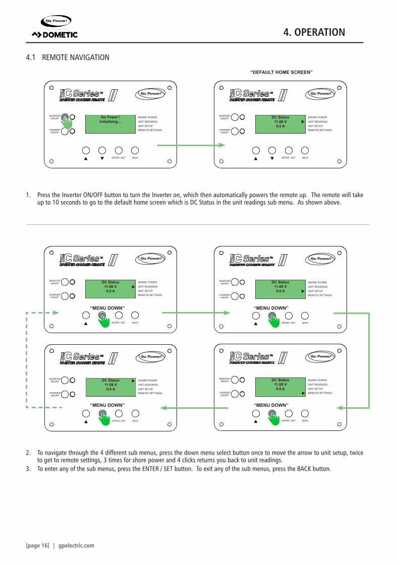
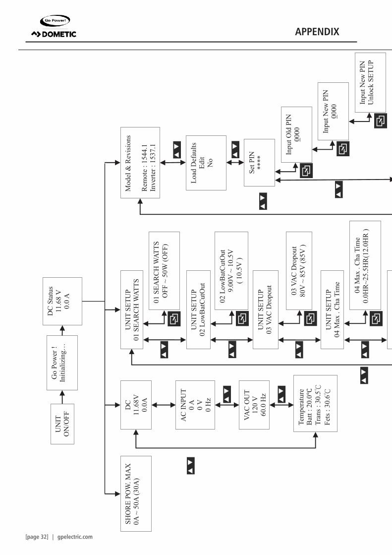
4.1 REMOTE NAVIGATION
SHORE POWER
UNIT READINGS
INVERTERON/OFF
CHARGERON/OFF
ENTER / SET BACK
UNIT SETUPREMOTE SETTINGS
®
SHORE POWER
UNIT READINGS
INVERTERON/OFF
CHARGERON/OFF
ENTER / SET BACK
UNIT SETUPREMOTE SETTINGS
®
SHORE POWER
UNIT READINGS
INVERTERON/OFF
CHARGERON/OFF
ENTER / SET BACK
UNIT SETUPREMOTE SETTINGS
®
SHORE POWER
UNIT READINGS
INVERTERON/OFF
CHARGERON/OFF
ENTER / SET BACK
UNIT SETUPREMOTE SETTINGS
®
SHORE POWER
UNIT READINGS
INVERTERON/OFF
CHARGERON/OFF
ENTER / SET BACK
UNIT SETUPREMOTE SETTINGS
®
SHORE POWER
UNIT READINGS
INVERTERON/OFF
CHARGERON/OFF
ENTER / SET BACK
UNIT SETUPREMOTE SETTINGS
®
Go Power !Initializing…
DC Status11.68 V0.0 A
DC Status11.68 V0.0 A
DC Status11.68 V0.0 A
DC Status11.68 V0.0 A
DC Status11.68 V0.0 A
1. Press the Inverter ON/OFF button to turn the Inverter on, which then automatically powers the remote up. The remote will take up to 10 seconds to go to the default home screen which is DC Status in the unit readings sub menu. As shown above.
2. To navigate through the 4 different sub menus, press the down menu select button once to move the arrow to unit setup, twice to get to remote settings, 3 times for shore power and 4 clicks returns you back to unit readings.
3. To enter any of the sub menus, press the ENTER / SET button. To exit any of the sub menus, press the BACK button.
“MENU DOWN”
“MENU DOWN”
“MENU DOWN”
“MENU DOWN”
“DEFAULT HOME SCREEN”
4. OPERATION
gpelectric.com | [page 17]
SHORE POWER
UNIT READINGS
INVERTERON/OFF
CHARGERON/OFF
ENTER / SET BACK
UNIT SETUPREMOTE SETTINGS
®
SHORE POWER
UNIT READINGS
INVERTERON/OFF
CHARGERON/OFF
ENTER / SET BACK
UNIT SETUPREMOTE SETTINGS
®
SHORE POWER
UNIT READINGS
INVERTERON/OFF
CHARGERON/OFF
ENTER / SET BACK
UNIT SETUPREMOTE SETTINGS
®
SHORE POWER
UNIT READINGS
INVERTERON/OFF
CHARGERON/OFF
ENTER / SET BACK
UNIT SETUPREMOTE SETTINGS
®
SHORE POWER
UNIT READINGS
INVERTERON/OFF
CHARGERON/OFF
ENTER / SET BACK
UNIT SETUPREMOTE SETTINGS
®
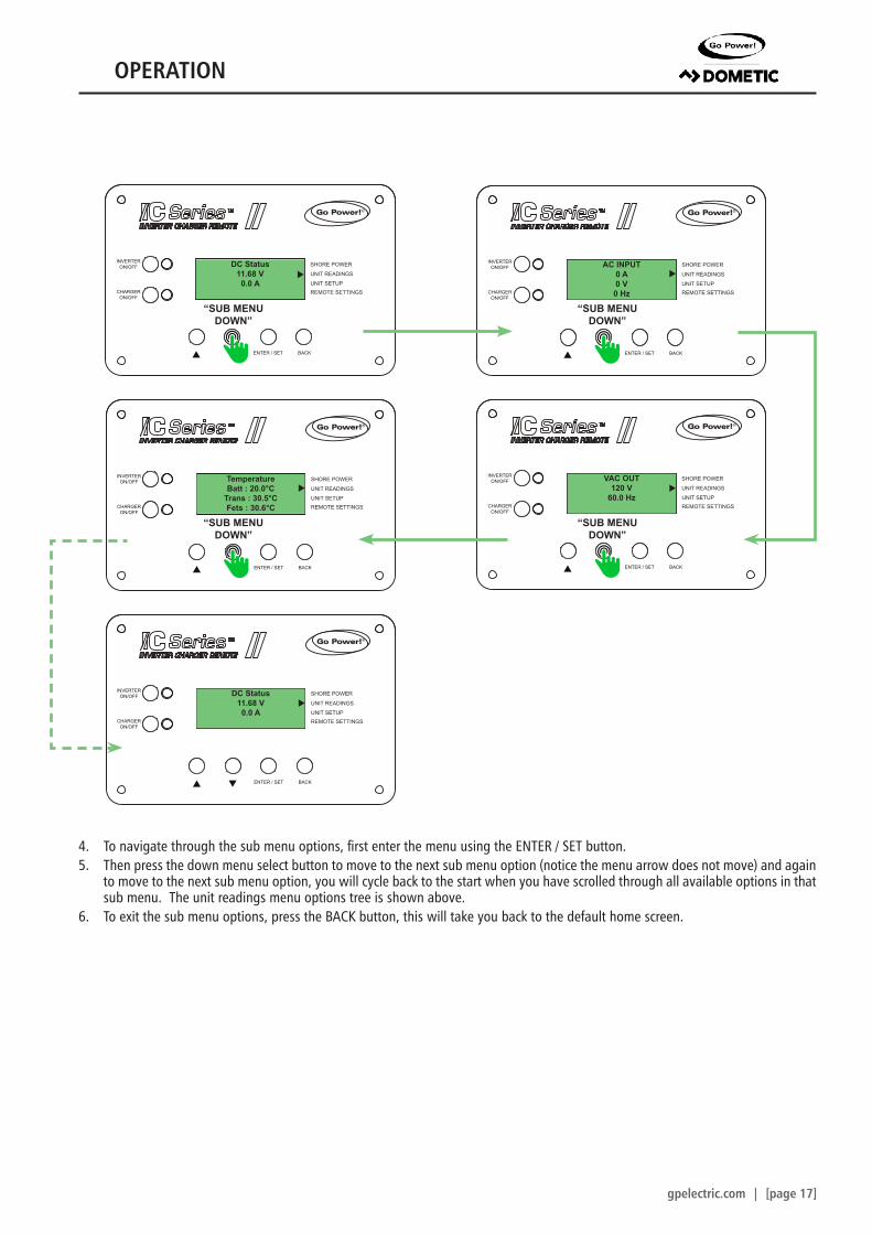
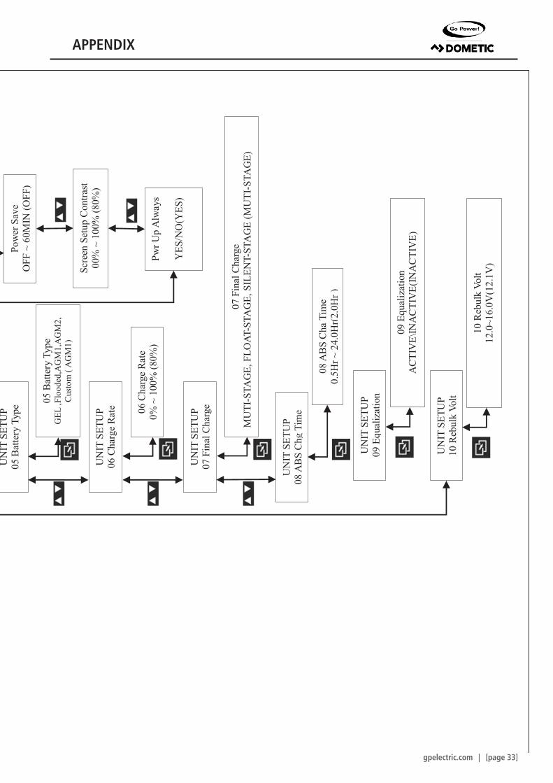
4. To navigate through the sub menu options, first enter the menu using the ENTER / SET button.5. Then press the down menu select button to move to the next sub menu option (notice the menu arrow does not move) and again
to move to the next sub menu option, you will cycle back to the start when you have scrolled through all available options in that sub menu. The unit readings menu options tree is shown above.
6. To exit the sub menu options, press the BACK button, this will take you back to the default home screen.
DC Status11.68 V0.0 A
AC INPUT0 A0 V
0 Hz
TemperatureBatt : 20.0°C
Trans : 30.5°CFets : 30.6°C
DC Status11.68 V0.0 A
VAC OUT120 V
60.0 Hz
“SUB MENU DOWN”
“SUB MENU DOWN”
“SUB MENU DOWN”
“SUB MENU DOWN”
OPERATION
[page 18] | gpelectric.com
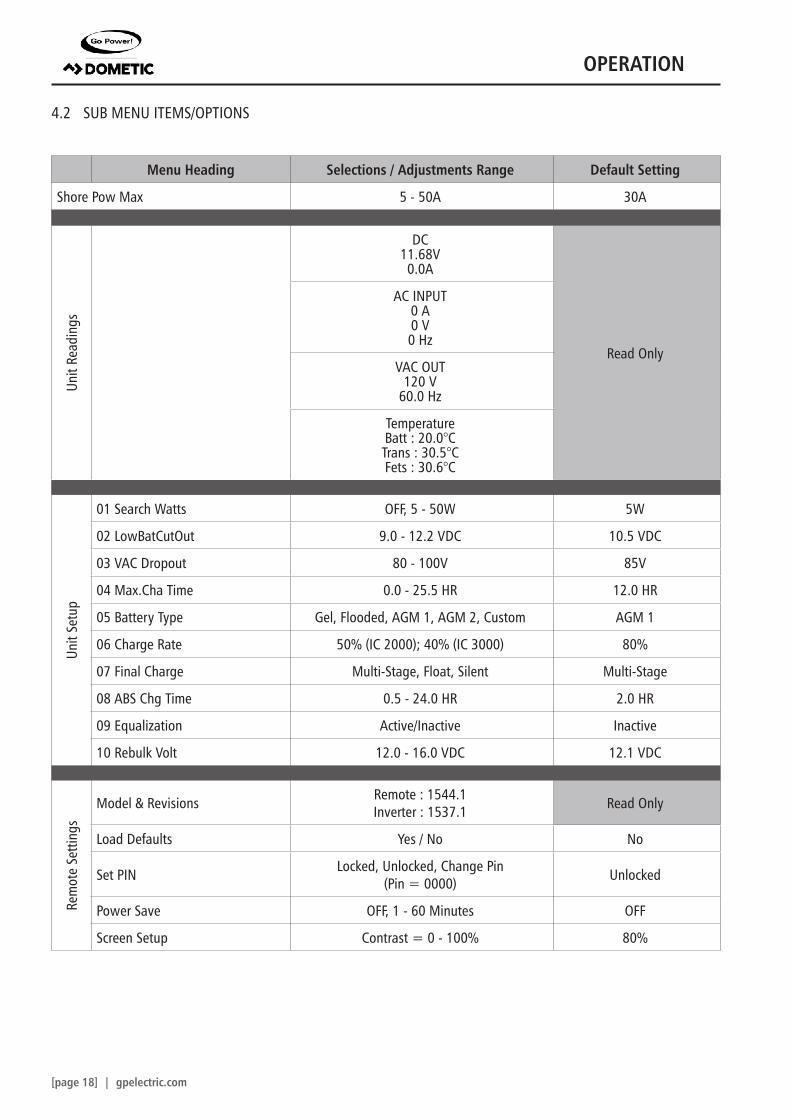
4.2 SUB MENU ITEMS/OPTIONS
Menu Heading Selections / Adjustments Range Default Setting
07 Final Charge Multi-Stage, Float, Silent Multi-Stage
08 ABS Chg Time 0.5 - 24.0 HR 2.0 HR
09 Equalization Active/Inactive Inactive
10 Rebulk Volt 12.0 - 16.0 VDC 12.1 VDC
Rem
ote
Setti
ngs
Model & Revisions Remote : 1544.1Inverter : 1537.1 Read Only
Load Defaults Yes / No No
Set PIN Locked, Unlocked, Change Pin (Pin = 0000) Unlocked
Power Save OFF, 1 - 60 Minutes OFF
Screen Setup Contrast = 0 - 100% 80%
OPERATION
gpelectric.com | [page 19]
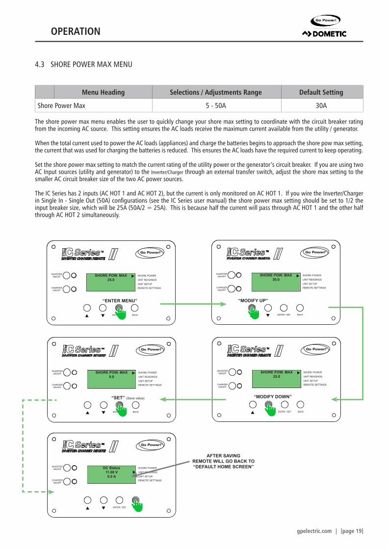
4.3 SHORE POWER MAX MENU
Menu Heading Selections / Adjustments Range Default Setting
Shore Power Max 5 - 50A 30A
The shore power max menu enables the user to quickly change your shore max setting to coordinate with the circuit breaker rating from the incoming AC source. This setting ensures the AC loads receive the maximum current available from the utility / generator.
When the total current used to power the AC loads (appliances) and charge the batteries begins to approach the shore pow max setting, the current that was used for charging the batteries is reduced. This ensures the AC loads have the required current to keep operating.
Set the shore power max setting to match the current rating of the utility power or the generator’s circuit breaker. If you are using two AC Input sources (utility and generator) to the Inverter/Charger through an external transfer switch, adjust the shore max setting to the smaller AC circuit breaker size of the two AC power sources.
The IC Series has 2 inputs (AC HOT 1 and AC HOT 2), but the current is only monitored on AC HOT 1. If you wire the Inverter/Charger in Single In - Single Out (50A) configurations (see the IC Series user manual) the shore power max setting should be set to 1/2 the input breaker size, which will be 25A (50A/2 = 25A). This is because half the current will pass through AC HOT 1 and the other half through AC HOT 2 simultaneously.
SHORE POWER
UNIT READINGS
INVERTERON/OFF
CHARGERON/OFF
ENTER / SET BACK
UNIT SETUPREMOTE SETTINGS
®
SHORE POWER
UNIT READINGS
INVERTERON/OFF
CHARGERON/OFF
ENTER / SET BACK
UNIT SETUPREMOTE SETTINGS
®
SHORE POW. MAX25.0
SHORE POW. MAX30.0
SHORE POWER
UNIT READINGS
INVERTERON/OFF
CHARGERON/OFF
ENTER / SET BACK
UNIT SETUPREMOTE SETTINGS
®
SHORE POWER
UNIT READINGS
INVERTERON/OFF
CHARGERON/OFF
ENTER / SET BACK
UNIT SETUPREMOTE SETTINGS
®
SHORE POW. MAX0.0
SHORE POW. MAX25.0
“ENTER MENU”
“SET” (Save value)
“MODIFY UP”
“MODIFY DOWN”
SHORE POWER
UNIT READINGS
INVERTERON/OFF
CHARGERON/OFF
ENTER / SET BACK
UNIT SETUPREMOTE SETTINGS
®
DC Status11.68 V0.0 A
AFTER SAVING REMOTE WILL GO BACK TO “DEFAULT HOME SCREEN”
OPERATION
[page 20] | gpelectric.com
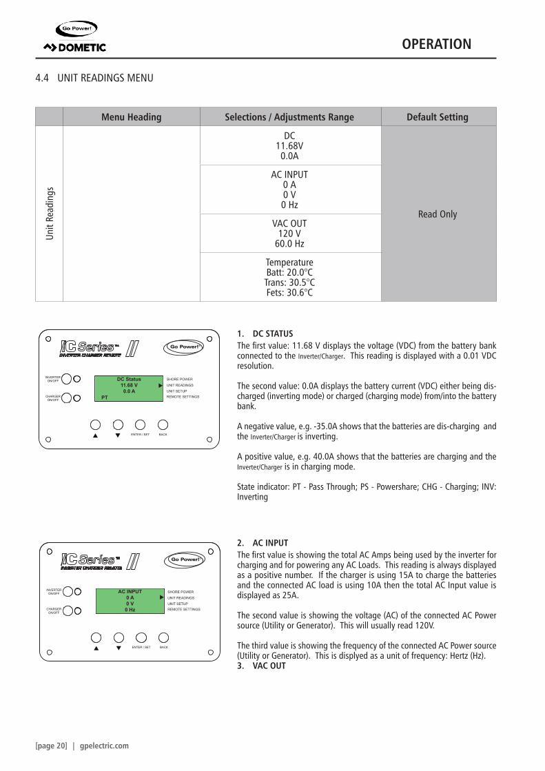
4.4 UNIT READINGS MENU
Menu Heading Selections / Adjustments Range Default Setting
Unit
Read
ings
DC11.68V0.0A
Read Only
AC INPUT0 A0 V0 Hz
VAC OUT120 V
60.0 Hz
TemperatureBatt: 20.0°CTrans: 30.5°CFets: 30.6°C
SHORE POWER
UNIT READINGS
INVERTERON/OFF
CHARGERON/OFF
ENTER / SET BACK
UNIT SETUPREMOTE SETTINGS
®
SHORE POWER
UNIT READINGS
INVERTERON/OFF
CHARGERON/OFF
ENTER / SET BACK
UNIT SETUPREMOTE SETTINGS
®
DC Status11.68 V0.0 A
AC INPUT0 A0 V0 Hz
1. DC STATUSThe first value: 11.68 V displays the voltage (VDC) from the battery bank connected to the Inverter/Charger. This reading is displayed with a 0.01 VDC resolution.
The second value: 0.0A displays the battery current (VDC) either being dis-charged (inverting mode) or charged (charging mode) from/into the battery bank.
A negative value, e.g. -35.0A shows that the batteries are dis-charging and the Inverter/Charger is inverting.
A positive value, e.g. 40.0A shows that the batteries are charging and the Inverter/Charger is in charging mode.
2. AC INPUTThe first value is showing the total AC Amps being used by the inverter for charging and for powering any AC Loads. This reading is always displayed as a positive number. If the charger is using 15A to charge the batteries and the connected AC load is using 10A then the total AC Input value is displayed as 25A.
The second value is showing the voltage (AC) of the connected AC Power source (Utility or Generator). This will usually read 120V.
The third value is showing the frequency of the connected AC Power source (Utility or Generator). This is displyed as a unit of frequency: Hertz (Hz).3. VAC OUT
PT
OPERATION
gpelectric.com | [page 21]
SHORE POWER
UNIT READINGS
INVERTERON/OFF
CHARGERON/OFF
ENTER / SET BACK
UNIT SETUPREMOTE SETTINGS
®
SHORE POWER
UNIT READINGS
INVERTERON/OFF
CHARGERON/OFF
ENTER / SET BACK
UNIT SETUPREMOTE SETTINGS
®
SHORE POWER
UNIT READINGS
INVERTERON/OFF
CHARGERON/OFF
ENTER / SET BACK
UNIT SETUPREMOTE SETTINGS
®
TemperatureBatt : 20.0°C
Trans : 30.5°CFets : 30.6°C
Unit Fault Code
No Fault
VAC OUT120 V
60.0 Hz
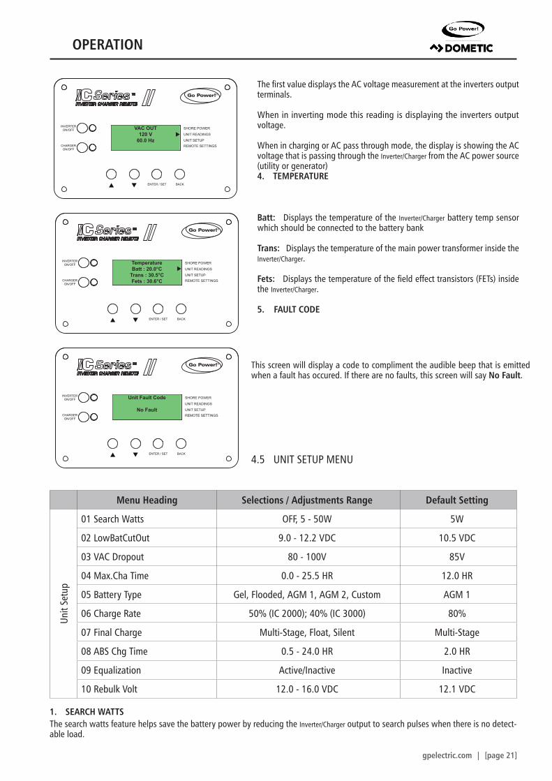
The first value displays the AC voltage measurement at the inverters output terminals.
When in inverting mode this reading is displaying the inverters output voltage.
When in charging or AC pass through mode, the display is showing the AC voltage that is passing through the Inverter/Charger from the AC power source (utility or generator)4. TEMPERATURE
Batt: Displays the temperature of the Inverter/Charger battery temp sensor which should be connected to the battery bank
Trans: Displays the temperature of the main power transformer inside the Inverter/Charger.
Fets: Displays the temperature of the field effect transistors (FETs) inside the Inverter/Charger.
5. FAULT CODE
Menu Heading Selections / Adjustments Range Default Setting
07 Final Charge Multi-Stage, Float, Silent Multi-Stage
08 ABS Chg Time 0.5 - 24.0 HR 2.0 HR
09 Equalization Active/Inactive Inactive
10 Rebulk Volt 12.0 - 16.0 VDC 12.1 VDC
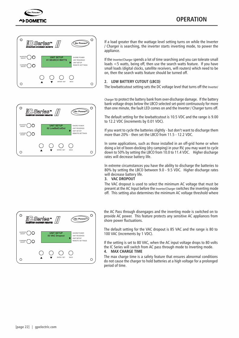
1. SEARCH WATTSThe search watts feature helps save the battery power by reducing the Inverter/Charger output to search pulses when there is no detect-able load.
This screen will display a code to compliment the audible beep that is emitted when a fault has occured. If there are no faults, this screen will say No Fault.
4.5 UNIT SETUP MENU
OPERATION
[page 22] | gpelectric.com
SHORE POWER
UNIT READINGS
INVERTERON/OFF
CHARGERON/OFF
ENTER / SET BACK
UNIT SETUPREMOTE SETTINGS
®
SHORE POWER
UNIT READINGS
INVERTERON/OFF
CHARGERON/OFF
ENTER / SET BACK
UNIT SETUPREMOTE SETTINGS
®
SHORE POWER
UNIT READINGS
INVERTERON/OFF
CHARGERON/OFF
ENTER / SET BACK
UNIT SETUPREMOTE SETTINGS
®
UNIT SETUP01 SEARCH WATTS
UNIT SETUP02 LowBatCutOut
UNIT SETUP03 VAC Dropout
If a load greater than the wattage level setting turns on while the Inverter / Charger is searching, the inverter starts inverting mode, to power the appliance.
If the Inverter/Charger spends a lot of time searching and you can tolerate small loads <5 watts, being off, then use the search watts feature. If you have small loads (digital clocks, satellite receivers, wifi routers) which need to be on, then the search watts feature should be turned off.
2. LOW BATTERY CUTOUT (LBCO)The lowbattcutout setting sets the DC voltage level that turns off the Inverter/
Charger to protect the battery bank from over-discharge damage. If the battery bank voltage drops below the LBCO selected set-point continuously for more than one minute, the fault LED comes on and the Inverter / Charger turns off.
The default setting for the lowbattcutout is 10.5 VDC and the range is 9.00 to 12.2 VDC (increments by 0.01 VDC).
If you want to cycle the batteries slightly - but don’t want to discharge them more than 20% - then set the LBCO from 11.5 - 12.2 VDC.
In some applications, such as those installed in an off-grid home or when doing a lot of boon-docking (dry camping) in your RV, you may want to cycle down to 50% by setting the LBCO from 10.0 to 11.4 VDC. Higher discharge rates will decrease battery life.
In extreme circumstances you have the ability to discharge the batteries to 80% by setting the LBCO between 9.0 - 9.5 VDC. Higher discharge rates will decrease battery life.3. VAC DROPOUTThe VAC dropout is used to select the minimum AC voltage that must be present at the AC Input before the Inverter/Charger switches the inverting mode off. This setting also determines the minimum AC voltage threshold where
the AC Pass through disengages and the inverting mode is switched on to provide AC power. This feature protects any sensitive AC appliances from shore power fluctuations.
The default setting for the VAC dropout is 85 VAC and the range is 80 to 100 VAC (increments by 1 VDC).
If the setting is set to 80 VAC, when the AC input voltage drops to 80 volts the IC Series will switch from AC pass through mode to Inverting mode.4. MAX CHARGE TIMEThe max charge time is a safety feature that ensures abnormal conditions do not cause the charger to hold batteries at a high voltage for a prolonged period of time.
OPERATION
gpelectric.com | [page 23]
SHORE POWER
UNIT READINGS
INVERTERON/OFF
CHARGERON/OFF
ENTER / SET BACK
UNIT SETUPREMOTE SETTINGS
®
SHORE POWER
UNIT READINGS
INVERTERON/OFF
CHARGERON/OFF
ENTER / SET BACK
UNIT SETUPREMOTE SETTINGS
®
UNIT SETUP04 Max . Cha Time
UNIT SETUP05 Battery Type
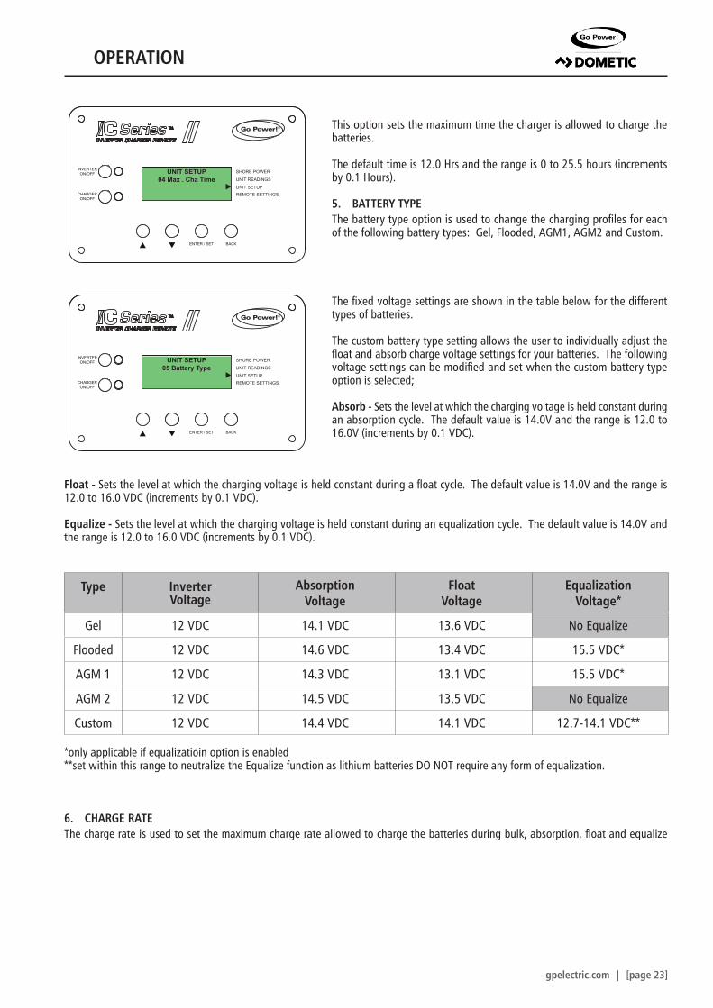
This option sets the maximum time the charger is allowed to charge the batteries.
The default time is 12.0 Hrs and the range is 0 to 25.5 hours (increments by 0.1 Hours).
5. BATTERY TYPEThe battery type option is used to change the charging profiles for each of the following battery types: Gel, Flooded, AGM1, AGM2 and Custom.
The fixed voltage settings are shown in the table below for the different types of batteries.
The custom battery type setting allows the user to individually adjust the float and absorb charge voltage settings for your batteries. The following voltage settings can be modified and set when the custom battery type option is selected;
Absorb - Sets the level at which the charging voltage is held constant during an absorption cycle. The default value is 14.0V and the range is 12.0 to 16.0V (increments by 0.1 VDC).
Float - Sets the level at which the charging voltage is held constant during a float cycle. The default value is 14.0V and the range is 12.0 to 16.0 VDC (increments by 0.1 VDC).
Equalize - Sets the level at which the charging voltage is held constant during an equalization cycle. The default value is 14.0V and the range is 12.0 to 16.0 VDC (increments by 0.1 VDC).
Type InverterVoltage
Absorption Voltage
Float Voltage
EqualizationVoltage*
Gel 12 VDC 14.1 VDC 13.6 VDC No Equalize
Flooded 12 VDC 14.6 VDC 13.4 VDC 15.5 VDC*
AGM 1 12 VDC 14.3 VDC 13.1 VDC 15.5 VDC*
AGM 2 12 VDC 14.5 VDC 13.5 VDC No Equalize
Custom 12 VDC 14.4 VDC 14.1 VDC 12.7-14.1 VDC**
*only applicable if equalizatioin option is enabled**set within this range to neutralize the Equalize function as lithium batteries DO NOT require any form of equalization.
6. CHARGE RATEThe charge rate is used to set the maximum charge rate allowed to charge the batteries during bulk, absorption, float and equalize
OPERATION
[page 24] | gpelectric.com
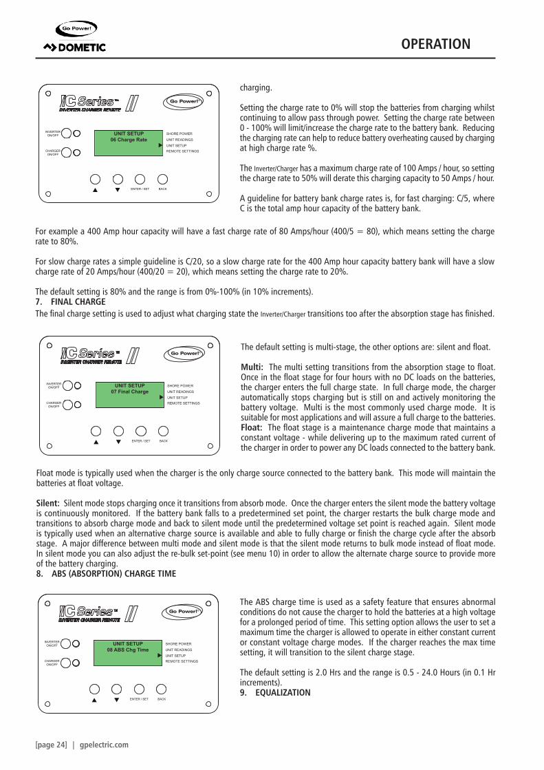
charging.
Setting the charge rate to 0% will stop the batteries from charging whilst continuing to allow pass through power. Setting the charge rate between 0 - 100% will limit/increase the charge rate to the battery bank. Reducing the charging rate can help to reduce battery overheating caused by charging at high charge rate %.
The Inverter/Charger has a maximum charge rate of 100 Amps / hour, so setting the charge rate to 50% will derate this charging capacity to 50 Amps / hour.
A guideline for battery bank charge rates is, for fast charging: C/5, where C is the total amp hour capacity of the battery bank.
SHORE POWER
UNIT READINGS
INVERTERON/OFF
CHARGERON/OFF
ENTER / SET BACK
UNIT SETUPREMOTE SETTINGS
®
SHORE POWER
UNIT READINGS
INVERTERON/OFF
CHARGERON/OFF
ENTER / SET BACK
UNIT SETUPREMOTE SETTINGS
®
SHORE POWER
UNIT READINGS
INVERTERON/OFF
CHARGERON/OFF
ENTER / SET BACK
UNIT SETUPREMOTE SETTINGS
®
UNIT SETUP06 Charge Rate
UNIT SETUP08 ABS Chg Time
UNIT SETUP07 Final Charge
The default setting is multi-stage, the other options are: silent and float.
Multi: The multi setting transitions from the absorption stage to float. Once in the float stage for four hours with no DC loads on the batteries, the charger enters the full charge state. In full charge mode, the charger automatically stops charging but is still on and actively monitoring the battery voltage. Multi is the most commonly used charge mode. It is suitable for most applications and will assure a full charge to the batteries.Float: The float stage is a maintenance charge mode that maintains a constant voltage - while delivering up to the maximum rated current of the charger in order to power any DC loads connected to the battery bank.
For example a 400 Amp hour capacity will have a fast charge rate of 80 Amps/hour (400/5 = 80), which means setting the charge rate to 80%.
For slow charge rates a simple guideline is C/20, so a slow charge rate for the 400 Amp hour capacity battery bank will have a slow charge rate of 20 Amps/hour (400/20 = 20), which means setting the charge rate to 20%.
The default setting is 80% and the range is from 0%-100% (in 10% increments).7. FINAL CHARGEThe final charge setting is used to adjust what charging state the Inverter/Charger transitions too after the absorption stage has finished.
Float mode is typically used when the charger is the only charge source connected to the battery bank. This mode will maintain the batteries at float voltage.
Silent: Silent mode stops charging once it transitions from absorb mode. Once the charger enters the silent mode the battery voltage is continuously monitored. If the battery bank falls to a predetermined set point, the charger restarts the bulk charge mode and transitions to absorb charge mode and back to silent mode until the predetermined voltage set point is reached again. Silent mode is typically used when an alternative charge source is available and able to fully charge or finish the charge cycle after the absorb stage. A major difference between multi mode and silent mode is that the silent mode returns to bulk mode instead of float mode. In silent mode you can also adjust the re-bulk set-point (see menu 10) in order to allow the alternate charge source to provide more of the battery charging.8. ABS (ABSORPTION) CHARGE TIME
The ABS charge time is used as a safety feature that ensures abnormal conditions do not cause the charger to hold the batteries at a high voltage for a prolonged period of time. This setting option allows the user to set a maximum time the charger is allowed to operate in either constant current or constant voltage charge modes. If the charger reaches the max time setting, it will transition to the silent charge stage.
The default setting is 2.0 Hrs and the range is 0.5 - 24.0 Hours (in 0.1 Hr increments). 9. EQUALIZATION
OPERATION
gpelectric.com | [page 25]
SHORE POWER
UNIT READINGS
INVERTERON/OFF
CHARGERON/OFF
ENTER / SET BACK
UNIT SETUPREMOTE SETTINGS
®
SHORE POWER
UNIT READINGS
INVERTERON/OFF
CHARGERON/OFF
ENTER / SET BACK
UNIT SETUPREMOTE SETTINGS
®
UNIT SETUP09 Equalization
UNIT SETUP10 Rebulk Volt
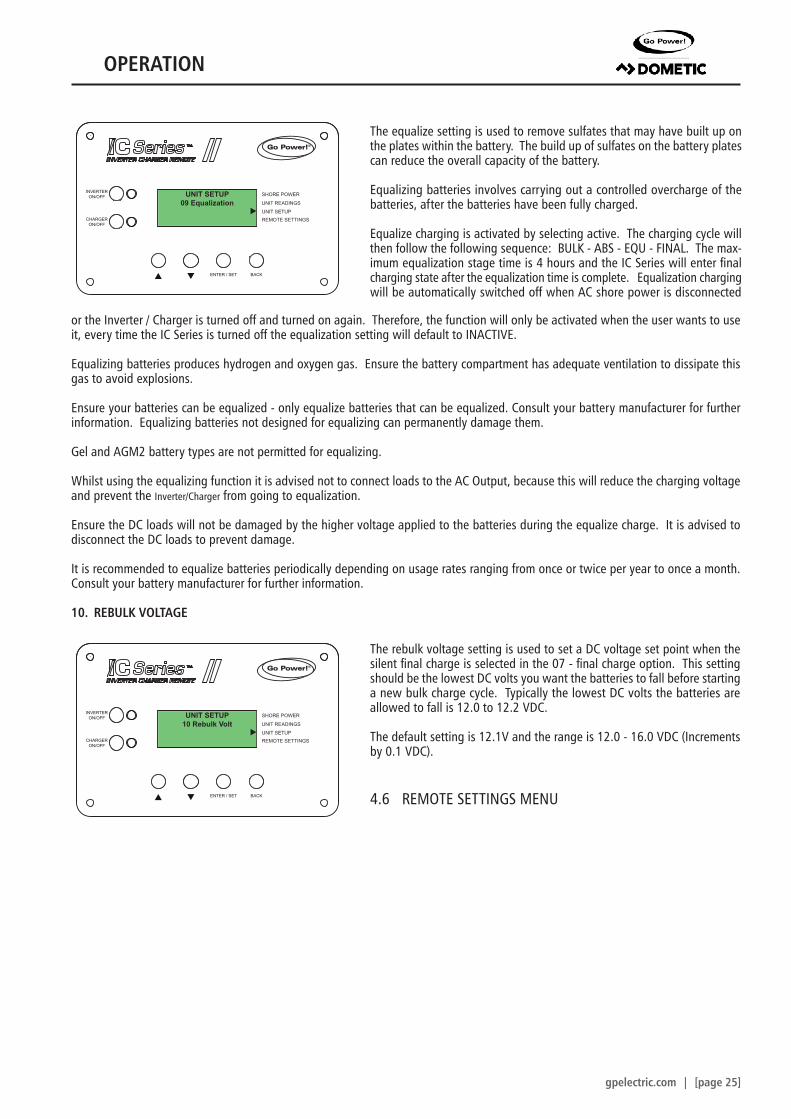
The equalize setting is used to remove sulfates that may have built up on the plates within the battery. The build up of sulfates on the battery plates can reduce the overall capacity of the battery.
Equalizing batteries involves carrying out a controlled overcharge of the batteries, after the batteries have been fully charged.
Equalize charging is activated by selecting active. The charging cycle will then follow the following sequence: BULK - ABS - EQU - FINAL. The max-imum equalization stage time is 4 hours and the IC Series will enter final charging state after the equalization time is complete. Equalization charging will be automatically switched off when AC shore power is disconnected
or the Inverter / Charger is turned off and turned on again. Therefore, the function will only be activated when the user wants to use it, every time the IC Series is turned off the equalization setting will default to INACTIVE.
Equalizing batteries produces hydrogen and oxygen gas. Ensure the battery compartment has adequate ventilation to dissipate this gas to avoid explosions.
Ensure your batteries can be equalized - only equalize batteries that can be equalized. Consult your battery manufacturer for further information. Equalizing batteries not designed for equalizing can permanently damage them.
Gel and AGM2 battery types are not permitted for equalizing.
Whilst using the equalizing function it is advised not to connect loads to the AC Output, because this will reduce the charging voltage and prevent the Inverter/Charger from going to equalization.
Ensure the DC loads will not be damaged by the higher voltage applied to the batteries during the equalize charge. It is advised to disconnect the DC loads to prevent damage.
It is recommended to equalize batteries periodically depending on usage rates ranging from once or twice per year to once a month. Consult your battery manufacturer for further information.
10. REBULK VOLTAGE
The rebulk voltage setting is used to set a DC voltage set point when the silent final charge is selected in the 07 - final charge option. This setting should be the lowest DC volts you want the batteries to fall before starting a new bulk charge cycle. Typically the lowest DC volts the batteries are allowed to fall is 12.0 to 12.2 VDC.
The default setting is 12.1V and the range is 12.0 - 16.0 VDC (Increments by 0.1 VDC).
4.6 REMOTE SETTINGS MENU
OPERATION
[page 26] | gpelectric.com
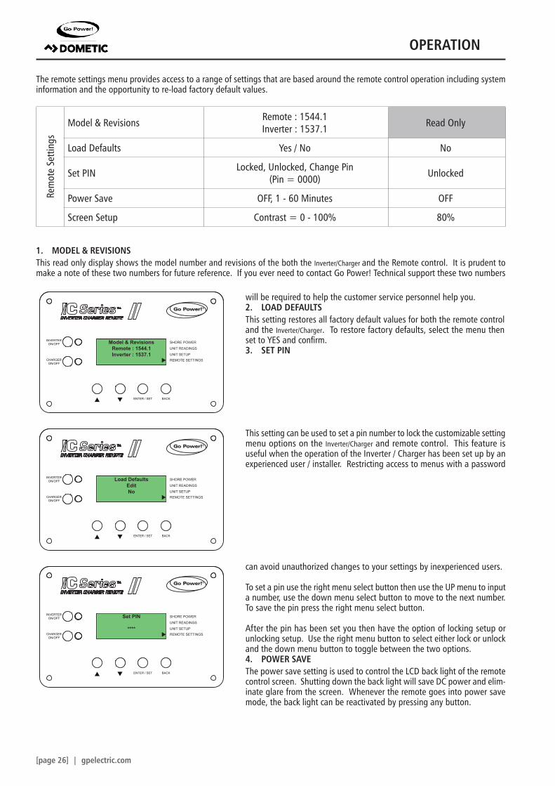
The remote settings menu provides access to a range of settings that are based around the remote control operation including system information and the opportunity to re-load factory default values.
Rem
ote
Setti
ngs
Model & Revisions Remote : 1544.1Inverter : 1537.1 Read Only
Load Defaults Yes / No No
Set PIN Locked, Unlocked, Change Pin (Pin = 0000) Unlocked
Power Save OFF, 1 - 60 Minutes OFF
Screen Setup Contrast = 0 - 100% 80%
1. MODEL & REVISIONSThis read only display shows the model number and revisions of the both the Inverter/Charger and the Remote control. It is prudent to make a note of these two numbers for future reference. If you ever need to contact Go Power! Technical support these two numbers
SHORE POWER
UNIT READINGS
INVERTERON/OFF
CHARGERON/OFF
ENTER / SET BACK
UNIT SETUPREMOTE SETTINGS
®
SHORE POWER
UNIT READINGS
INVERTERON/OFF
CHARGERON/OFF
ENTER / SET BACK
UNIT SETUPREMOTE SETTINGS
®
SHORE POWER
UNIT READINGS
INVERTERON/OFF
CHARGERON/OFF
ENTER / SET BACK
UNIT SETUPREMOTE SETTINGS
®
Model & RevisionsRemote : 1544.1Inverter : 1537.1
Load DefaultsEditNo
Set PIN
****
will be required to help the customer service personnel help you.2. LOAD DEFAULTSThis setting restores all factory default values for both the remote control and the Inverter/Charger. To restore factory defaults, select the menu then set to YES and confirm.3. SET PIN
This setting can be used to set a pin number to lock the customizable setting menu options on the Inverter/Charger and remote control. This feature is useful when the operation of the Inverter / Charger has been set up by an experienced user / installer. Restricting access to menus with a password
can avoid unauthorized changes to your settings by inexperienced users.
To set a pin use the right menu select button then use the UP menu to input a number, use the down menu select button to move to the next number. To save the pin press the right menu select button.
After the pin has been set you then have the option of locking setup or unlocking setup. Use the right menu button to select either lock or unlock and the down menu button to toggle between the two options.4. POWER SAVEThe power save setting is used to control the LCD back light of the remote control screen. Shutting down the back light will save DC power and elim-inate glare from the screen. Whenever the remote goes into power save mode, the back light can be reactivated by pressing any button.
OPERATION
gpelectric.com | [page 27]
SHORE POWER
UNIT READINGS
INVERTERON/OFF
CHARGERON/OFF
ENTER / SET BACK
UNIT SETUPREMOTE SETTINGS
®
SHORE POWER
UNIT READINGS
INVERTERON/OFF
CHARGERON/OFF
ENTER / SET BACK
UNIT SETUPREMOTE SETTINGS
®
Power SaveOFF
Screen SetupContrast = 80%
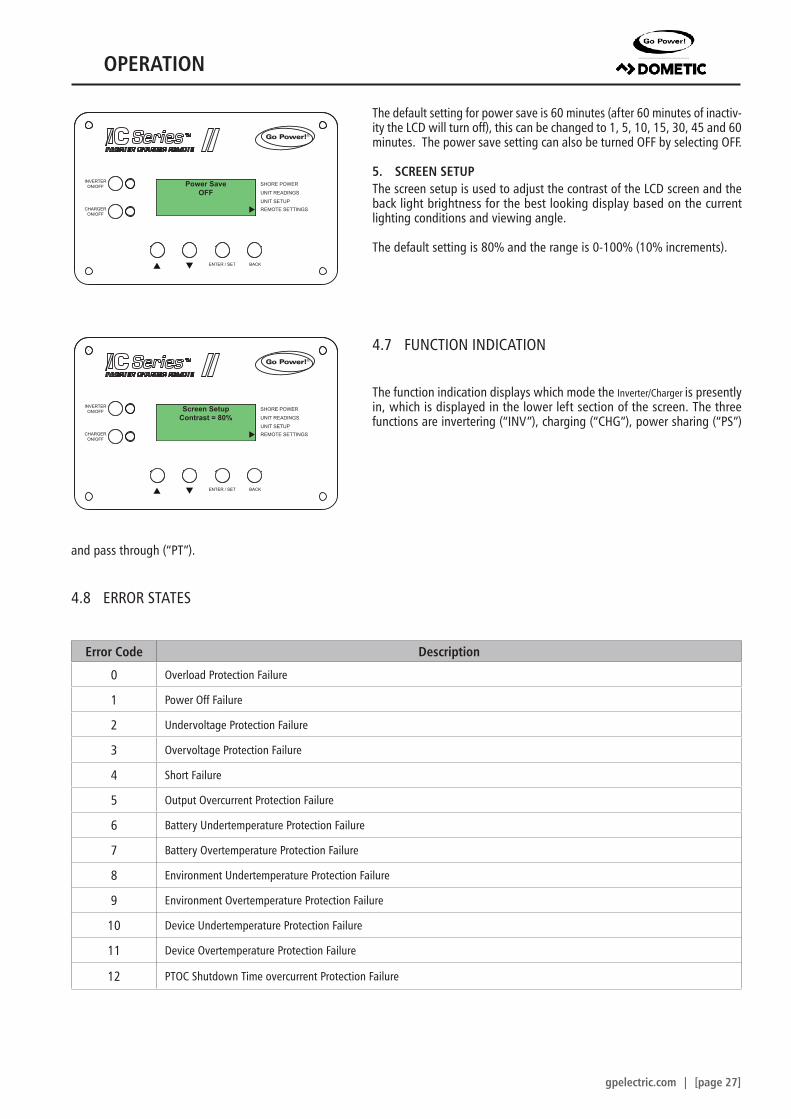
The default setting for power save is 60 minutes (after 60 minutes of inactiv-ity the LCD will turn off), this can be changed to 1, 5, 10, 15, 30, 45 and 60 minutes. The power save setting can also be turned OFF by selecting OFF.
5. SCREEN SETUPThe screen setup is used to adjust the contrast of the LCD screen and the back light brightness for the best looking display based on the current lighting conditions and viewing angle.
The default setting is 80% and the range is 0-100% (10% increments).
4.7 FUNCTION INDICATION
The function indication displays which mode the Inverter/Charger is presently in, which is displayed in the lower left section of the screen. The three functions are invertering (“INV”), charging (“CHG”), power sharing (“PS”)
and pass through (“PT”).
4.8 ERROR STATES
Error Code Description
0 Overload Protection Failure
1 Power Off Failure
2 Undervoltage Protection Failure
3 Overvoltage Protection Failure
4 Short Failure
5 Output Overcurrent Protection Failure
6 Battery Undertemperature Protection Failure
7 Battery Overtemperature Protection Failure
8 Environment Undertemperature Protection Failure
9 Environment Overtemperature Protection Failure
10 Device Undertemperature Protection Failure
11 Device Overtemperature Protection Failure
12 PTOC Shutdown Time overcurrent Protection Failure
OPERATION
[page 28] | gpelectric.com
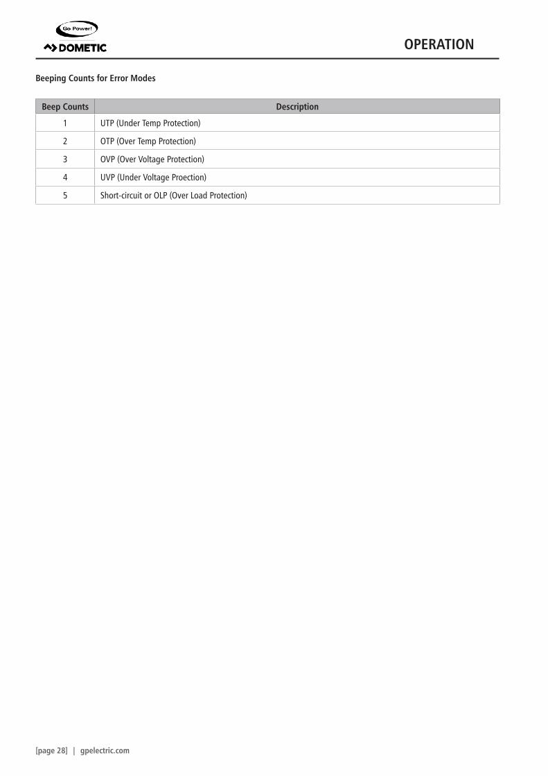
Beeping Counts for Error Modes
Beep Counts Description
1 UTP (Under Temp Protection)
2 OTP (Over Temp Protection)
3 OVP (Over Voltage Protection)
4 UVP (Under Voltage Proection)
5 Short-circuit or OLP (Over Load Protection)
OPERATION
gpelectric.com | [page 29]
The Go Power! warranty is valid against defects in materials and workmanship for the specific product warranty period. It is not valid against defects resulting from, but not limited to:
• Misuse and/or abuse, neglect or accident• Exceeding the unit’s design limits• Improper installation, including, but not limited to, improper environmental protection and improper hook-up• Acts of God, including lightning, floods, earthquakes, fire, and high winds• Damage in handling, including damage encountered during shipment
A warranty shall be considered void if the warranted product is in any way opened or altered. The warranty will be void if any eyelet, rivets, or other fasteners used to seal the unit are removed or altered, or if the unit’s serial number is in any way removed, altered, replaced, defaced, or rendered illegible.
Warranty Return ProcedureBefore contacting Go Power!’s customer service department, please read the “frequently asked questions” section of our website to troubleshoot the problem. If trouble persists:
1. Call your Go Power!™ Technical Support team (1-866-247-6527) or2. Return defective product to place of purchase
Unless approved by Go Power! Management, all product shipped collect to Go Power! will be refused. Test items or items that are not under warranty, or units that are not defective, will be charged a minimum bench charge of ($50.00 US) plus taxes and shipping. A 15% restocking charge will be applied on goods returned and accepted as “new” stock.
An RMA number (Return Materials Authorization number) from Go Power! Customer Service is required prior to returning any Go Power! Products. Go Power! reserves the right to refuse any items sent to Go Power! without an associated RMA number. To obtain an RMA number, please contact [email protected] or or call Toll Free (for US & Canada) 1-866-247-6527. Out of WarrantyGo Power! electronic products are non-repairable, Go Power! does not perform repairs on its products nor does it contract out those repairs to a third party. Go Power! does not supply schematics or replacement parts for any of its electronic products.
5. WARRANTY RETURN PROCEDURE
[page 30] | gpelectric.com
www.earth911.com/recycling-center-search-guidesLocal recycling centres can be found here;
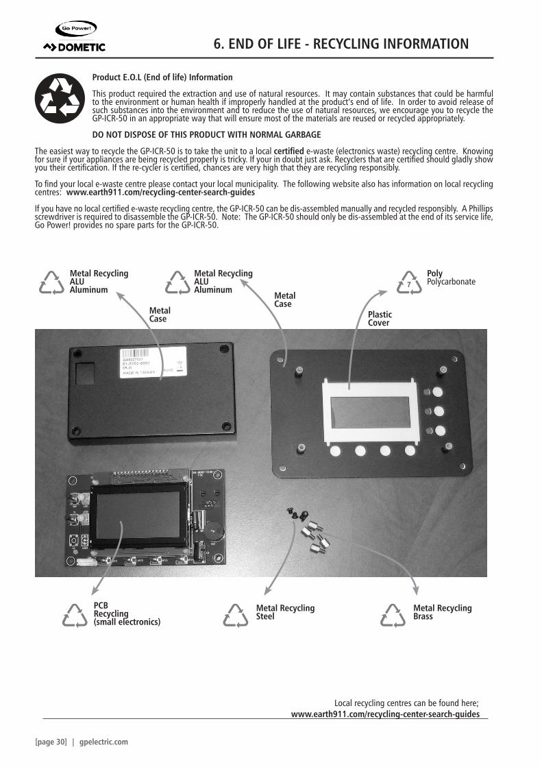
Product E.O.L (End of life) Information
This product required the extraction and use of natural resources. It may contain substances that could be harmful to the environment or human health if improperly handled at the product’s end of life. In order to avoid release of such substances into the environment and to reduce the use of natural resources, we encourage you to recycle the GP-ICR-50 in an appropriate way that will ensure most of the materials are reused or recycled appropriately.
DO NOT DISPOSE OF THIS PRODUCT WITH NORMAL GARBAGE
The easiest way to recycle the GP-ICR-50 is to take the unit to a local certified e-waste (electronics waste) recycling centre. Knowing for sure if your appliances are being recycled properly is tricky. If your in doubt just ask. Recyclers that are certified should gladly show you their certification. If the re-cycler is certified, chances are very high that they are recycling responsibly.
To find your local e-waste centre please contact your local municipality. The following website also has information on local recycling centres: www.earth911.com/recycling-center-search-guides
If you have no local certified e-waste recycling centre, the GP-ICR-50 can be dis-assembled manually and recycled responsibly. A Phillips screwdriver is required to disassemble the GP-ICR-50. Note: The GP-ICR-50 should only be dis-assembled at the end of its service life, Go Power! provides no spare parts for the GP-ICR-50.