Remote deformation field measurement through different mediausing fiber optics
J. A. Gilbert*T. D. DudderarA. NosetAT &T Bell LaboratoriesMurray Hill, New Jersey 07974
CONTENTS1. Introduction2. Prior related research3. Experiments4. Discussion5. Conclusions6. Acknowledgments7. References
Abstract. This series of tests demonstrates the feasibility of recording deforma-tion holograms of reflecting subjects that are not mounted on an optical benchand vibration - isolated and that, in fact, can even be submerged in a transparentliquid. This represents an important extension of research into the use of fiberoptics in holography. Various considerations for the ultimate development of apractical fiber optic device for making in -situ or "production environment"deformation field measurements by continuous wave holographic interferome-try are also discussed.
Subject terms: holographic interferometry; fiber optics in holography; continuous waveholographic interferometry; production environment measurements; submerged objects;stress analysis; deformation measurement.
1. INTRODUCTIONFiber optics, which were originally developed for communicationsnetworks, are finding new applications in other areas. Individualfibers are now being used in transducers to measure displacement,pressure, torque, etc. Fiber bundles, on the other hand, have proveninvaluable in medicine when used as tools for inspection in deviceslike cystoscopes and endoscopes. Boroscopes are used in industrialapplications to view remote or otherwise inaccessible regions ofstructures. Other applications are even more unique; for example,optical fiber bundles are used as "eyes" in robots as part of theirclosed -loop feedback system. In short, fiber optic technology israpidly being incorporated into a variety of practical devices.
Many more sophisticated instruments use combinations ofindividual fibers and fiber bundles to transmit light amplitude. Theseinclude the laserscope, which is being designed to burn passagewaysthrough clogged arteries and uses some fibers to conduct the main laserbeam, a fiber bundle for inspection, and still other fibers for illumina-tion. Other fiber -based systems rely on the transmission of both ampli-tude and phase. For example, two of the authors have recentlyestablished the feasibility of measuring deformation fields on remote
*Associate Professor of Engineering Mechanics, Dept. of Civil Engineering, Univ. ofWisconsin -Milwaukee, Milwaukee, Wis. 53201.tGraduate student in Engineering Mechanics, Dept. of Civil Engineering, Univ. ofWisconsin -Milwaukee, Milwaukee, Wis. 53201.
Invited Paper HI -103 received Nov. 26, 1984; accepted for publication Jan. 28, 1985;received by Managing Editor April I, 1985. This paper is a revision of a paper which waspublished in the Spring Conference Proceedings of the Society for Experimental StressAnalysis , Brookfield Center, Conn., pp. 424 -430 (1983).e 1985 Society of Photo -Optical Instrumentation Engineers.
surfaces by applying the techniques of holographic interferometrythrough fiber optics. An individual fiber is used to illuminate the testsubject while a coherent fiber bundle transmits image amplitude andphase information back from the object to the hologram. This paperexpands the scope of this prior holographic/ fiber optic research andoutlines some of the steps required for the potential subsequent devel-opment of a practical device designed to make production -related orin -situ holographic deformation measurements.
2. PRIOR RELATED RESEARCHFiber optics were first used in holography as the reference wave inrecording a hologram or as the illuminating wave in reconstructingit.I,2 Although fibers were used in the object beam to illuminate thetest surface,3.4 scattered wavefronts recorded on the hologram werenot captured through fiber optics, and direct optical access to the testsurface was required. These studies established basic feasibility forholographic recording with fiber optics but did not take deformationmeasurement into account.
Prior research in scattered light and image plane holography5.6led one of the authors to develop a holographic technique in which acoherent bundle was inserted between the object and the photo-graphic plate. Amplitude and phase information could then be con-veyed to the hologram for subsequent displacement analysis in caseswhere optical access was limited.? These concepts were expanded,8and displacement was measured over the full field using coherentmultimode bundles (MMBs) made up from individual step indexfibers. Unfortunately, these fibers transmitted more than one wave-front, and adequate stability could only be assured when fiber ele-ments were rigidly mounted throughout their length. Since then,considerable effort has been directed toward understanding the lightpropagation characteristics of optical fibers and developing tech-niques to ensure that both amplitude and phase information remainsstable during holographic recordings. A significant breakthroughwas made by two of the authors using monomode (single -mode atX = 633 nm) optical fiber designed and manufactured by AT &T BellLaboratories.9 Results showed that single -mode fibers (SMFs) pro-vided a means of transmitting stable coherent illumination to thevicinity of the object surface and/ or hologram and requiring only
Remote deformation field measurement through different media using fiber optics
J. A. Gilbert* T. D. Dudderar A. NosetAT&T Bell Laboratories Murray Hill, New Jersey 07974
Abstract. This series of tests demonstrates the feasibility of recording deforma tion holograms of reflecting subjects that are not mounted on an optical bench and vibration-isolated and that, in fact, can even be submerged in a transparent liquid. This represents an important extension of research into the use of fiber optics in holography. Various considerations for the ultimate development of a practical fiber optic device for making in-situ or "production environment" deformation field measurements by continuous wave holographic interferome- try are also discussed.
CONTENTS1. Introduction2. Prior related research3. Experiments4. Discussion5. Conclusions6. Acknowledgments7. References
1. INTRODUCTIONFiber optics, which were originally developed for communications networks, are finding new applications in other areas. Individual fibers are now being used in transducers to measure displacement, pressure, torque, etc. Fiber bundles, on the other hand, have proven invaluable in medicine when used as tools for inspection in devices like cystoscopes and endoscopes. Boroscopes are used in industrial applications to view remote or otherwise inaccessible regions of structures. Other applications are even more unique; for example, optical fiber bundles are used as "eyes" in robots as part of their closed-loop feedback system. In short, fiber optic technology is rapidly being incorporated into a variety of practical devices.
Many more sophisticated instruments use combinations of individual fibers and fiber bundles to transmit light amplitude. These include the laserscope, which is being designed to burn passageways through clogged arteries and uses some fibers to conduct the main laser beam, a fiber bundle for inspection, and still other fibers for illumina tion. Other fiber-based systems rely on the transmission of both ampli tude and phase. For example, two of the authors have recently established the feasibility of measuring deformation fields on remote
*Associate Professor of Engineering Mechanics, Dept. of Civil Engineering, Univ. of Wisconsin-Milwaukee, Milwaukee, Wis. 53201.fGraduate student in Engineering Mechanics, Dept. of Civil Engineering, Univ. of Wisconsin-Milwaukee, Milwaukee, Wis. 53201.
surfaces by applying the techniques of holographic interferometry through fiber optics. An individual fiber is used to illuminate the test subject while a coherent fiber bundle transmits image amplitude and phase information back from the object to the hologram. This paper expands the scope of this prior holographic/fiber optic research and outlines some of the steps required for the potential subsequent devel opment of a practical device designed to make production-related or in-situ holographic deformation measurements.
2. PRIOR RELATED RESEARCHFiber optics were first used in holography as the reference wave in recording a hologram or as the illuminating wave in reconstructing it. 1 ' 2 Although fibers were used in the object beam to illuminate the test surface, 3 ' 4 scattered wavefronts recorded on the hologram were not captured through fiber optics, and direct optical access to the test surface was required. These studies established basic feasibility for holographic recording with fiber optics but did not take deformation measurement into account.
Prior research in scattered light and image plane holography 5 ' 6 led one of the authors to develop a holographic technique in which a coherent bundle was inserted between the object and the photo graphic plate. Amplitude and phase information could then be con veyed to the hologram for subsequent displacement analysis in cases where optical access was limited. 7 These concepts were expanded,8 and displacement was measured over the full field using coherent multimode bundles (MMBs) made up from individual step index fibers. Unfortunately, these fibers transmitted more than one wave- front, and adequate stability could only be assured when fiber ele ments were rigidly mounted throughout their length. Since then, considerable effort has been directed toward understanding the light propagation characteristics of optical fibers and developing tech niques to ensure that both amplitude and phase information remains stable during holographic recordings. A significant breakthrough was made by two of the authors using monomode (single-mode at A = 633 nm) optical fiber designed and manufactured by AT&T Bell Laboratories. 9 Results showed that single-mode fibers (SMFs) pro vided a means of transmitting stable coherent illumination to the vicinity of the object surface and/or hologram and requiring only
Downloaded From: http://opticalengineering.spiedigitallibrary.org/ on 09/13/2013 Terms of Use: http://spiedl.org/terms
REMOTE DEFORMATION FIELD MEASUREMENT THROUGH DIFFERENT MEDIA USING FIBER OPTICS
that the ends of each fiber be rigidly anchored.In these pioneer deformation studies, fiber optics were used to
increase the flexibility of the holographic setup and to decrease thenumber of required optical components. Optical fiber could easily bearranged to provide the close matching of path lengths needed tosatisfy coherence requirements and to gain access to remote areas ofthe test object. The position of the fibers in the system could bequickly modified (1) to change the location of the source or the pointof observation in order to record different scalar displacement com-ponents or (2) to vary the spatial frequency content of the hologram.
The achievement of low spatial frequency is of fundamentalimportance in another holographic/ fiber optic stability study by theauthors.1° In that work the object and reference beams were firstcombined at a remote location following transmission throughpaired SMFs. The resulting standing wave intensity pattern was thentransmitted back through an MMB to the recording site. This tech-nique is also being applied to deformation measurement, although itspotential is somewhat limited because such holograms are of rela-tively poor resolution. Its major advantage, however, is that thestability requirements on the recording system are decreased sincethe MMB is used for amplitude (as opposed to phase) transmission.
So far, all holographic testing with fiber optics has been carriedout under laboratory conditions in uncirculating room air and on avibration -isolated optical bench -the same stringent laboratoryconditions required for conventional holographic testing. There is,however, a growing desire to apply holography and holographicinterferometry in production- related or in -situ environments, manyof which require testing on nonisolated, remote surfaces located inmedia different from air. Watson and Britton, for example, havedemonstrated an approach to performing optical holographyunderwater for purposes of inspection and archiving." Their systemwas fairly complicated and did not involve the use of fiber opticelements. The successful development of holographic/ fiber opticdeformation recording systems, on the other hand, should furthersuch efforts and lead to the development of new systems with manyunique practical applications since fiber optics provide reasonablyflexible and environmentally insensitive light guides. For example, afiber network could be used to monitor deformation at several testsites located throughout an industrial test floor, while the holo-graphic patterns could be recorded and analyzed at a central process-ing location. A device, similar to the laserscope, could be developedto make holographic deformation measurements on human organsfor diagnostic purposes. Other applications might include testing innuclear environments and deformation analysis on ship hulls andsubmarines.
This paper demonstrates that holographic interferograms can berecorded through fiber optics from surfaces located off the vibration -isolated optical bench and, in some cases, underwater. These investi-gations constitute a portion of the fundamental research that must beperformed before holographic techniques can be applied in the typesof practical problems described above.
3. EXPERIMENTSSeveral tests were conducted to demonstrate the feasibility of record-ing deformation through fiber optics from nonisolated test surfacesthat may be submerged in water.
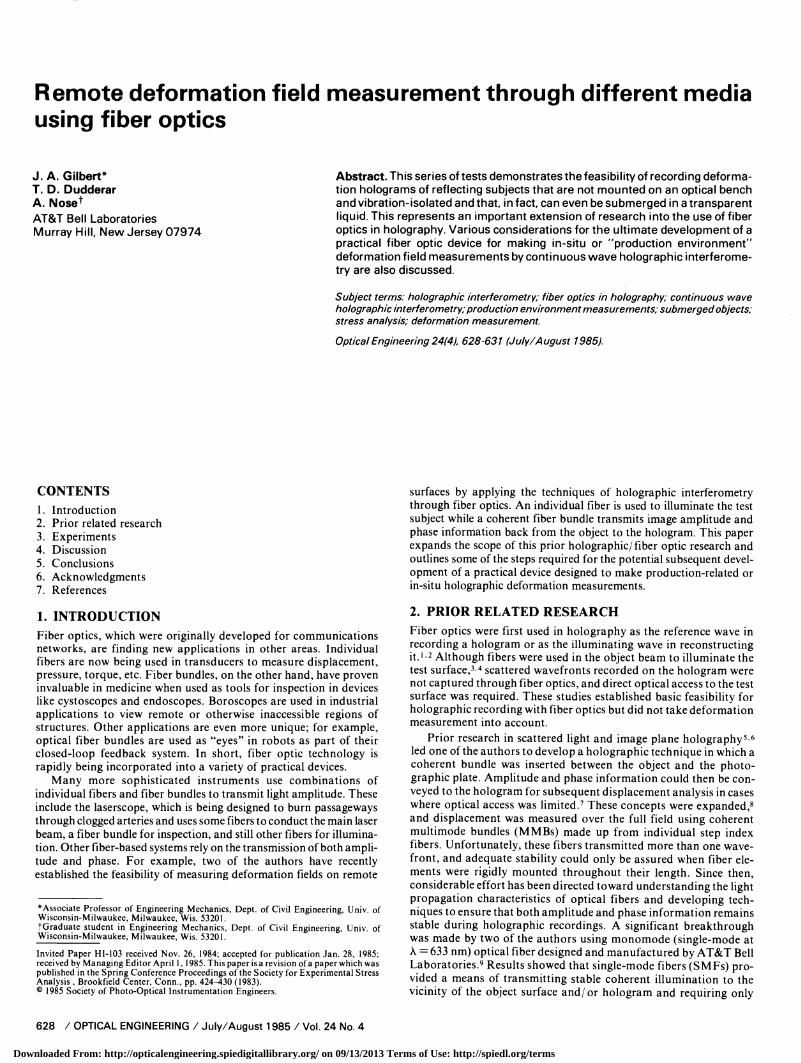
Figure 1 shows the experimental setup used to record the dis-placement field of the object. All optical components were vibration -isolated except for optical fibers in tests conducted on models locatedoff the optical bench. A HeNe laser (X = 632.8 nm) was used as acoherent light source. Light from the laser was launched through a5 X microscope objective into a single -mode fiber having a numericalaperture (NA) equal to 0.1159 and a core diameter of 7.3 µm. Lightemerging from the exit end of the fiber illuminated a portion of thecantilever beam (length L = 23.8 cm) shown in Figs. 2 and 3. The sizeof the illuminated area was dependent upon the index of refraction ofthe test environment. The regions 0 5 X/ L .40.21 and 0 X/ L 0.16were illuminated in tests conducted in air and underwater,respectively.
A coherent multimode fiber bundle (MMB of 4 mm diameter,having a resolution of 27 lines/ mm and composed of individual12 -µm- diameter multimode fibers) was used to transmit the image ofthe test subject from the test site to the photographic plate. A Selfocmicrolens was used to image the illuminated surface onto theentrance end of the MMB (the acceptance angle of the lens alsodepends upon the index of refraction of the surrounding medium andis smaller in water than in air). The real image transmitted throughthe MMB was focused on the photographic plate and combined witha collimated reference beam to form an image plane hologram. Asecond SM F could have been used to generate the reference beam. Inthe present study, however, this would be of little advantage except,perhaps, as a convenient means of equalizing object and referencebeam path lengths.
For small beam deflections, the significant displacement compo-nent lies parallel to the Z -axis, and for a concentrated intermediateloading W, this deflection w at a distance X from the fixed end isgiven by 12
w =WXZ
6EI(3b - X) forO -<.X ,
(1)
Wbz
w 6E (3X-b) for b ,
where E is Young's modulus, I is the moment of inertia, and b is theX- coordinate at which the load is applied.
A double- exposure holographic technique was used to recordholograms. First, a hologram of the undeformed surface was takenduring an initial exposure. After a displacement of 25.4 X 10⁻⁴ cmwas applied at X/ L = 0.75, a second hologram was recorded on the
REMOTE DEFORMATION FIELD MEASUREMENT THROUGH DIFFERENT MEDIA USING FIBER OPTICS
that the ends of each fiber be rigidly anchored.In these pioneer deformation studies, fiber optics were used to
increase the flexibility of the holographic setup and to decrease the number of required optical components. Optical fiber could easily be arranged to provide the close matching of path lengths needed to satisfy coherence requirements and to gain access to remote areas of the test object. The position of the fibers in the system could be quickly modified (1) to change the location of the source or the point of observation in order to record different scalar displacement com ponents or (2) to vary the spatial frequency content of the hologram.
The achievement of low spatial frequency is of fundamental importance in another holographic/fiber optic stability study by the authors. 10 In that work the object and reference beams were first combined at a remote location following transmission through paired SMFs. The resulting standing wave intensity pattern was then transmitted back through an MMB to the recording site. This tech nique is also being applied to deformation measurement, although its potential is somewhat limited because such holograms are of rela tively poor resolution. Its major advantage, however, is that the stability requirements on the recording system are decreased since the MMB is used for amplitude (as opposed to phase) transmission.
So far, all holographic testing with fiber optics has been carried out under laboratory conditions in uncirculating room air and on a vibration-isolated optical bench the same stringent laboratory conditions required for conventional holographic testing. There is, however, a growing desire to apply holography and holographic interferometry in production-related or in-situ environments, many of which require testing on nonisolated, remote surfaces located in media different from air. Watson and Britton, for example, have demonstrated an approach to performing optical holography underwater for purposes of inspection and archiving. 11 Their system was fairly complicated and did not involve the use of fiber optic elements. The successful development of holographic/fiber optic deformation recording systems, on the other hand, should further such efforts and lead to the development of new systems with many unique practical applications since fiber optics provide reasonably flexible and environmentally insensitive light guides. For example, a fiber network could be used to monitor deformation at several test sites located throughout an industrial test floor, while the holo graphic patterns could be recorded and analyzed at a central process ing location. A device, similar to the laserscope, could be developed to make holographic deformation measurements on human organs for diagnostic purposes. Other applications might include testing in nuclear environments and deformation analysis on ship hulls and submarines.
This paper demonstrates that holographic interferograms can be recorded through fiber optics from surfaces located off the vibration- isolated optical bench and, in some cases, underwater. These investi gations constitute a portion of the fundamental research that must be performed before holographic techniques can be applied in the types of practical problems described above.
3. EXPERIMENTSSeveral tests were conducted to demonstrate the feasibility of record ing deformation through fiber optics from nonisolated test surfaces that may be submerged in water.
Figure 1 shows the experimental setup used to record the dis placement field of the object. All optical components were vibration- isolated except for optical fibers in tests conducted on models located off the optical bench. A HeNe laser (A = 632.8 nm) was used as a coherent light source. Light from the laser was launched through a 5 X microscope objective into a single-mode fiber having a numerical aperture (NA) equal to 0.1159 and a core diameter of 7.3 /im. Light emerging from the exit end of the fiber illuminated a portion of the cantilever beam (length L = 23.8 cm) shown in Figs. 2 and 3. The size of the illuminated area was dependent upon the index of refraction of the test environment. The regions 0<X/ L <0.21 and 0 <X/ L <0.16 were illuminated in tests conducted in air and underwater, respectively.
A coherent multimode fiber bundle (MMB of 4 mm diameter, having a resolution of 27 lines/mm and composed of individual 12-/nn-diameter multimode fibers) was used to transmit the image of the test subject from the test site to the photographic plate. A Selfoc microlens was used to image the illuminated surface onto the entrance end of the MMB (the acceptance angle of the lens also depends upon the index of refraction of the surrounding medium and is smaller in water than in air). The real image transmitted through the MMB was focused on the photographic plate and combined with a collimated reference beam to form an image plane hologram. A second SMF could have been used to generate the reference beam. In the present study, however, this would be of little advantage except, perhaps, as a convenient means of equalizing object and reference beam path lengths.
For small beam deflections, the significant displacement compo nent lies parallel to the Z-axis, and for a concentrated intermediate loading W, this deflection w at a distance X from the fixed end is given by 12
w =WX2 ~6Ef -(3b-X)
(1)
w =Wb2
6EI (3X-b) forb^X^L
where E is Young's modulus, I is the moment of inertia, and b is the X-coordinate at which the load is applied.
A double-exposure holographic technique was used to record holograms. First, a hologram of the undeformed surface was taken during an initial exposure. After a displacement of 25.4 X 10~4 cm was applied at X/ L = 0.75, a second hologram was recorded on the
Downloaded From: http://opticalengineering.spiedigitallibrary.org/ on 09/13/2013 Terms of Use: http://spiedl.org/terms
GILBERT, DUDDERAR, NOSE
Fig. 2. Cantilever beam.
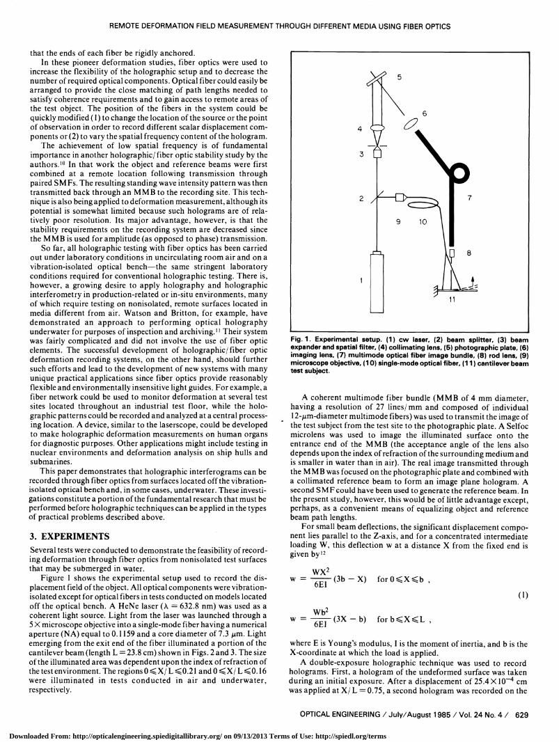
same photographic plate so that the deformed state was super-imposed on the undeformed state. The photographic plate was thendeveloped and reconstructed using white light to reveal the inter-ference fringe or deformation pattern. This test was repeated for fourdifferent situations, namely, with the cantilever beam located (I) on avibration isolation table and in air, (2) off a vibration isolation tableand in air, (3) on a vibration isolation table and underwater, and (4)off a vibration isolation table and underwater. Holograms wererecorded on Kodak 131 high speed holographic plates and werebleached using bromine. In all cases the exposure time was 12 s perexposure, and in cases (3) and (4) the temperature of the water was23° C.
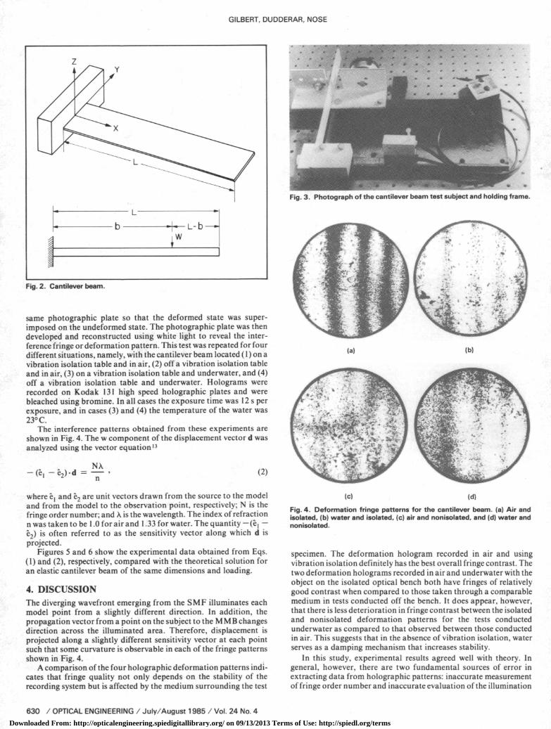
The interference patterns obtained from these experiments areshown in Fig. 4. The w component of the displacement vector d wasanalyzed using the vector equation13
Na-(ê1 -ê2)d=-, (2)
where êl and ê2 are unit vectors drawn from the source to the modeland from the model to the observation point, respectively; N is thefringe order number; and X is the wavelength. The index of refractionn was taken to be 1.0 for air and 1.33 for water. The quantity - (ê1 -e2) is often referred to as the sensitivity vector along which d isprojected.
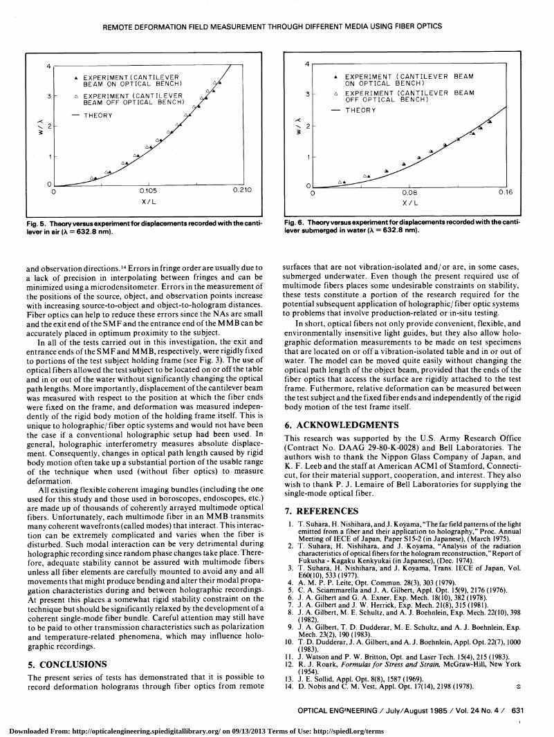
Figures 5 and 6 show the experimental data obtained from Eqs.(1) and (2), respectively, compared with the theoretical solution foran elastic cantilever beam of the same dimensions and loading.
4. DISCUSSIONThe diverging wavefront emerging from the SMF illuminates eachmodel point from a slightly different direction. In addition, thepropagation vector from a point on the subject to the M M B changesdirection across the illuminated area. Therefore, displacement isprojected along a slightly different sensitivity vector at each pointsuch that some curvature is observable in each of the fringe patternsshown in Fig. 4.
A comparison of the four holographic deformation patterns indi-cates that fringe quality not only depends on the stability of therecording system but is affected by the medium surrounding the test
Fig. 3. Photograph of the cantilever beam test subject and holding frame.
(a) (b)
(c) (d)
Fig. 4. Deformation fringe patterns for the cantilever beam. (a) Air andisolated, (b) water and isolated, (c) air and nonisolated, and (d) water andnonisolated.
specimen. The deformation hologram recorded in air and usingvibration isolation definitely has the best overall fringe contrast. Thetwo deformation holograms recorded in air and underwater with theobject on the isolated optical bench both have fringes of relativelygood contrast when compared to those taken through a comparablemedium in tests conducted off the bench. It does appear, however,that there is less deterioration in fringe contrast between the isolatedand nonisolated deformation patterns for the tests conductedunderwater as compared to that observed between those conductedin air. This suggests that in the absence of vibration isolation, waterserves as a damping mechanism that increases stability.
In this study, experimental results agreed well with theory. Ingeneral, however, there are two fundamental sources of error inextracting data from holographic patterns: inaccurate measurementof fringe order number and inaccurate evaluation of the illumination
GILBERT, DUDDERAR, NOSE
-L-b-iW
Fig. 2. Cantilever beam.
same photographic plate so that the deformed state was super imposed on the undeformed state. The photographic plate was then developed and reconstructed using white light to reveal the inter ference fringe or deformation pattern. This test was repeated for four different situations, namely, with the cantilever beam located (1) on a vibration isolation table and in air, (2) off a vibration isolation table and in air, (3) on a vibration isolation table and underwater, and (4) off a vibration isolation table and underwater. Holograms were recorded on Kodak 131 high speed holographic plates and were bleached using bromine. In all cases the exposure time was 12 s per exposure, and in cases (3) and (4) the temperature of the water was 23° C.
The interference patterns obtained from these experiments are shown in Fig. 4. The w component of the displacement vector d was analyzed using the vector equation 13
NX —— (2)
where Cj and e2 are unit vectors drawn from the source to the model and from the model to the observation point, respectively; N is the fringe order number; and X is the wavelength. The index of refraction n was taken to be 1.0 for air and 1.33 for water. The quantity (e, e2 ) is often referred to as the sensitivity vector along which d is projected.
Figures 5 and 6 show the experimental data obtained from Eqs. (1) and (2), respectively, compared with the theoretical solution for an elastic cantilever beam of the same dimensions and loading.
4. DISCUSSIONThe diverging wavefront emerging from the SMF illuminates each model point from a slightly different direction. In addition, the propagation vector from a point on the subject to the MMB changes direction across the illuminated area. Therefore, displacement is projected along a slightly different sensitivity vector at each point such that some curvature is observable in each of the fringe patterns shown in Fig. 4.
A comparison of the four holographic deformation patterns indi cates that fringe quality not only depends on the stability of the recording system but is affected by the medium surrounding the test
Fig. 3. Photograph of the cantilever beam test subject and holding frame.
(a} (b)
Fig. 4. Deformation fringe patterns for the cantilever beam, (a) Air and isolated, (b) water and isolated, (c) air and nonisolated, and (d) water and no n isolated.
specimen. The deformation hologram recorded in air and using vibration isolation definitely has the best overall fringe contrast. The two deformation holograms recorded in air and underwater with the object on the isolated optical bench both have fringes of relatively good contrast when compared to those taken through a comparable medium in tests conducted off the bench. It does appear, however, that there is less deterioration in fringe contrast between the isolated and nonisolated deformation patterns for the tests conducted underwater as compared to that observed between those conducted in air. This suggests that in the absence of vibration isolation, water serves as a damping mechanism that increases stability.
In this study, experimental results agreed well with theory. In general, however, there are two fundamental sources of error in extracting data from holographic patterns: inaccurate measurement of fringe order number and inaccurate evaluation of the illumination
Downloaded From: http://opticalengineering.spiedigitallibrary.org/ on 09/13/2013 Terms of Use: http://spiedl.org/terms
REMOTE DEFORMATION FIELD MEASUREMENT THROUGH DIFFERENT MEDIA USING FIBER OPTICS
EXPERIMENT (CANTILEVERBEAM ON OPTICAL BENCH)
o EXPERIMENT (CANTILEVERBEAM OFF OPTICAL BENCH)
- THEORY
0.105 0.210
X/L
Fig. 5. Theory versus experiment for displacements recorded with the cantilever in air (A = 632.8 nm).
and observation directions.14 Errors in fringe order are usually due toa lack of precision in interpolating between fringes and can beminimized using a microdensitometer. Errors in the measurement ofthe positions of the source, object, and observation points increasewith increasing source -to- object and object -to- hologram distances.Fiber optics can help to reduce these errors since the NAs are smalland the exit end of the SMF and the entrance end of the MMB can beaccurately placed in optimum proximity to the subject.
In all of the tests carried out in this investigation, the exit andentrance ends of the SMF and M MB, respectively, were rigidly fixedto portions of the test subject holding frame (see Fig. 3). The use ofoptical fibers allowed the test subject to be located on or off the tableand in or out of the water without significantly changing the opticalpath lengths. More importantly, displacement of the cantilever beamwas measured with respect to the position at which the fiber endswere fixed on the frame, and deformation was measured indepen-dently of the rigid body motion of the holding frame itself. This isunique to holographic / fiber optic systems and would not have beenthe case if a conventional holographic setup had been used. Ingeneral, holographic interferometry measures absolute displace-ment. Consequently, changes in optical path length caused by rigidbody motion often take up a substantial portion of the usable rangeof the technique when used (without fiber optics) to measuredeformation.
All existing flexible coherent imaging bundles (including the oneused for this study and those used in boroscopes, endoscopes, etc.)are made up of thousands of coherently arrayed multimode opticalfibers. Unfortunately, each multimode fiber in an MMB transmitsmany coherent wavefronts (called modes) that interact. This interac-tion can be extremely complicated and varies when the fiber isdisturbed. Such modal interaction can be very detrimental duringholographic recording since random phase changes take place. There-fore, adequate stability cannot be assured with multimode fibersunless all fiber elements are carefully mounted to avoid any and allmovements that might produce bending and alter their modal propa-gation characteristics during and between holographic recordings.At present this places a somewhat rigid stability constraint on thetechnique but should be significantly relaxed by the development of acoherent single -mode fiber bundle. Careful attention may still haveto be paid to other transmission characteristics such as polarizationand temperature -related phenomena, which may influence holo-graphic recordings.
5. CONCLUSIONSThe present series of tests has demonstrated that it is possible torecord deformation holograms through fiber optics from remote
4
3
2
EXPERIMENT (CANTILEVER BEAMON OPTICAL BENCH)
A EXPERIMENT (CANTILEVER BEAMOFF OPTICAL BENCH)
- THEORY
o0 0.08
X/L0.16
Fig. 6. Theory versus experiment for displacements recorded with the canti-lever submerged in water (a = 632.8 nm).
surfaces that are not vibration -isolated and/ or are, in some cases,submerged underwater. Even though the present required use ofmultimode fibers places some undesirable constraints on stability,these tests constitute a portion of the research required for thepotential subsequent application of holographic/ fiber optic systemsto problems that involve production -related or in -situ testing.
In short, optical fibers not only provide convenient, flexible, andenvironmentally insensitive light guides, but they also allow holo-graphic deformation measurements to be made on test specimensthat are located on or off a vibration -isolated table and in or out ofwater. The model can be moved quite easily without changing theoptical path length of the object beam, provided that the ends of thefiber optics that access the surface are rigidly attached to the testframe. Futhermore, relative deformation can be measured betweenthe test subject and the fixed fiber ends and independently of the rigidbody motion of the test frame itself.
6. ACKNOWLEDGMENTSThis research was supported by the U.S. Army Research Office(Contract No. DAAG 29 -80 -K -0028) and Bell Laboratories. Theauthors wish to thank the Nippon Glass Company of Japan, andK. F. Leeb and the staff at American ACMI of Stamford, Connecti-cut, for their material support, cooperation, and interest. They alsowish to thank P. J. Lemaire of Bell Laboratories for supplying thesingle -mode optical fiber.
7. REFERENCESI . T. Suhara, H. Nishihara, and J. Koyama, "The far field patterns of the light
emitted from a fiber and their application to holography," Proc. AnnualMeeting of IECE of Japan, Paper S15 -2 (in Japanese), (March 1975).
2. T. Suhara, H. Nishihara, and J. Koyama, "Analysis of the radiationcharacteristics of optical fibers for the hologram reconstruction," Report ofFukusha - Kagaku Kenkyukai (in Japanese), (Dec. 1974).
3. T. Suhara, H. Nishihara, and J. Koyama, Trans. IECE of Japan, Vol.E60(I0), 533 (1977).
4. A. M. P. P. Leite, Opt. Commun. 28(3), 303 (1979).5. C. A. Sciammarella and J. A. Gilbert, Appl. Opt. 15(9), 2176 (1976).6. J. A. Gilbert and G. A. Exner, Exp. Mech. 18(10), 382 (1978).7. J. A. Gilbert and J. W. Herrick, Exp. Mech. 21(8), 315 (1981).8. J. A. Gilbert, M. E. Schultz, and A. J. Boehnlein, Exp. Mech. 22(10), 398
(1982).9. J. A. Gilbert, T. D. Dudderar, M. E. Schultz, and A. J. Boehnlein, Exp.
Mech. 23(2), 190 (1983).10. T. D. Dudderar, J. A. Gilbert, and A. J. Boehnlein, Appl. Opt. 22(7), 1000
(1983).11. J. Watson and P. W. Britton, Opt. and Laser Tech. 15(4), 215 (1983).12. R. J. Roark, Formulas for Stress and Strain, McGraw -Hill, New York
(1954).13. J. E. Sollid, Appl. Opt. 8(8), 1587 (1969).14. D. Nobis and C. M. Vest, Appl. Opt. 17(14), 2198 (1978).
REMOTE DEFORMATION FIELD MEASUREMENT THROUGH DIFFERENT MEDIA USING FIBER OPTICS
* EXPERIMENT(CANTILEVER BEAM ON OPTICAL BENCH)
A EXPERIMENT (CANTILEVER BEAM OFF OPTICAL BENCH)
— THEORY
0.210
Fig. 5. Theory versus experiment for displacements recorded with the canti lever in air (A = 632.8 nm).
EXPERIMENT (CANTILEVER BEAM ON OPTICAL BENCH)
EXPERIMENT (CANTILEVER BEAM OFF OPTICAL BENCH)
— THEORY
0.16
Fig. 6. Theory versus experiment for displacements recorded with the canti lever submerged in water (X = 632.8 nm).
and observation directions. M Errors in fringe order are usually due to a lack of precision in interpolating between fringes and can be minimized using a microdensitometer. Errors in the measurement of the positions of the source, object, and observation points increase with increasing source-to-object and object-to-hologram distances. Fiber optics can help to reduce these errors since the NAs are small and the exit end of the SMF and the entrance end of the MMB can be accurately placed in optimum proximity to the subject.
In all of the tests carried out in this investigation, the exit and entrance ends of the SMF and MMB, respectively, were rigidly fixed to portions of the test subject holding frame (see Fig. 3). The use of optical fibers allowed the test subject to be located on or off the table and in or out of the water without significantly changing the optical path lengths. More importantly, displacement of the cantilever beam was measured with respect to the position at which the fiber ends were fixed on the frame, and deformation was measured indepen dently of the rigid body motion of the holding frame itself. This is unique to holographic/fiber optic systems and would not have been the case if a conventional holographic setup had been used. In general, holographic interferometry measures absolute displace ment. Consequently, changes in optical path length caused by rigid body motion often take up a substantial portion of the usable range of the technique when used (without fiber optics) to measure deformation.
All existing flexible coherent imaging bundles (including the one used for this study and those used in boroscopes, endoscopes, etc.) are made up of thousands of coherently arrayed multimode optical fibers. Unfortunately, each multimode fiber in an MMB transmits many coherent wavefronts (called modes) that interact. This interac tion can be extremely complicated and varies when the fiber is disturbed. Such modal interaction can be very detrimental during holographic recording since random phase changes take place. There fore, adequate stability cannot be assured with multimode fibers unless all fiber elements are carefully mounted to avoid any and all movements that might produce bending and alter their modal propa gation characteristics during and between holographic recordings. At present this places a somewhat rigid stability constraint on the technique but should be significantly relaxed by the development of a coherent single-mode fiber bundle. Careful attention may still have to be paid to other transmission characteristics such as polarization and temperature-related phenomena, which may influence holo graphic recordings.
5. CONCLUSIONSThe present series of tests has demonstrated that it is possible to record deformation holograms through fiber optics from remote
surfaces that are not vibration-isolated and/or are, in some cases, submerged underwater. Even though the present required use of multimode fibers places some undesirable constraints on stability, these tests constitute a portion of the research required for the potential subsequent application of holographic/fiber optic systems to problems that involve production-related or in-situ testing.
In short, optical fibers not only provide convenient, flexible, and environmentally insensitive light guides, but they also allow holo graphic deformation measurements to be made on test specimens that are located on or off a vibration-isolated table and in or out of water. The model can be moved quite easily without changing the optical path length of the object beam, provided that the ends of the fiber optics that access the surface are rigidly attached to the test frame. Futhermore, relative deformation can be measured between the test subject and the fixed fiber ends and independently of the rigid body motion of the test frame itself.
6. ACKNOWLEDGMENTSThis research was supported by the U.S. Army Research Office (Contract No. DAAG 29-80-K-0028) and Bell Laboratories. The authors wish to thank the Nippon Glass Company of Japan, and K. F. Leeb and the staff at American ACMI of Stamford, Connecti cut, for their material support, cooperation, and interest. They also wish to thank P. J. Lemaire of Bell Laboratories for supplying the single-mode optical fiber.
7. REFERENCES1. T. Suhara, H. Nishihara, and J. Koyama, "The far field patterns of the light
emitted from a fiber and their application to holography," Proc. Annual Meeting of IECE of Japan, Paper S15-2 (in Japanese), (March 1975).
2. T. Suhara, H. Nishihara, and J. Koyama, "Analysis of the radiation characteristics of optical fibers for the hologram reconstruction," Report of Fukusha - Kagaku Kenkyukai (in Japanese), (Dec. 1974).
3. T. Suhara, H. Nishihara, and J. Koyama, Trans. IECE of Japan, Vol. £60(10), 533(1977).
4. A. M. P. P. Leite, Opt. Commun. 28(3), 303 (1979).5. C. A. Sciammarella and J. A. Gilbert, Appl. Opt. 15(9), 2176 (1976).6. J. A. Gilbert and G. A. Exner, Exp. Mech. 18(10), 382 (1978).7. J. A. Gilbert and J. W. Herrick, Exp. Mech. 21(8), 315 (1981).8. J. A. Gilbert, M. E. Schultz, and A. J. Boehnlein, Exp. Mech. 22(10), 398
(1982).9. J. A. Gilbert, T. D. Dudderar, M. E. Schultz, and A. J. Boehnlein, Exp.
Mech. 23(2), 190(1983).10. T. D. Dudderar, J. A. Gilbert, and A. J. Boehnlein, Appl. Opt. 22(7), 1000
(1983).11. J. Watson and P. W. Britton, Opt. and Laser Tech. 15(4), 215 (1983).12. R. J. Roark, Formulas for Stress and Strain, McGraw-Hill, New York
(1954).13. J. E. Sollid, Appl. Opt. 8(8), 1587 (1969).14. D. Nobis and C. M. Vest, Appl. Opt. 17(14), 2198 (1978). s