Page 1
Remote GPU-Accelerated Online Pre-processing of
Raster Maps for Terrain Rendering
Rolf Westerteiger∗?, Fang Chen∗, Andreas Gerndt∗, Bernd Hamann†, Hans Hagen?.
∗ German Aerospace Center †UC Davis ? TU Kaiserslautern
Lilienthalplatz 7 Shields Avenue 1 Gottlieb-Daimler-Strasse
38108 Braunschweig 95616-8562, Davis, CA 67663 Kaiserslautern
Germany U.S.A. Germany
[email protected] [email protected] [email protected]
Abstract: We present a distributed architecture for accelerated pre-processing of remote
sensing data for immediate terrain visualization. Interactive 3D visualization approaches
for large terrain datasets employ level of detail techniques that require a multi-resolution
data representation. The high computational cost of constructing these representations is
often not viewed as a major drawback, as it is considered an off-line pre-processing step.
This prevents the application of existing methods in the case of changing data, which is
becoming increasingly important for a multitude of applications where datasets are being
generated, transmitted and must be visualized immediately, such as in disaster management.
Our system uses graphics processing units (GPUs) to accelerate the process of generating
a multi-resolution representation, achieving sufficient performance to enable on-line visu-
alization on a front-end workstation communicating with a back-end cluster of machines
equipped with GPUs. As a reference data structure, we use a quad tree decomposition
of the so-called HEALPix sphere parameterization, which is well-suited for spherical ter-
rain rendering. Our system correctly handles overlapping and unregistered mixed-resolution
datasets. We demonstrate the efficacy of our approach by applying it to the surface of Mars
using both the NASA Mars Orbiter Laser Altimeter and the ESA Mars Express High Reso-
lution Stereo Camera datasets.
Keywords: terrain rendering, pre-processing, gpu
1 Introduction
Interactive three-dimensional terrain visualization has become accessible to a wide audience
due to the development of advanced rendering algorithms which can guarantee interactivity
at very high resolutions. With the emergence of inexpensive remote sensing platforms such
as quadcopters, future challenges will include the integration and visualization of changing
data collected from multiple sources such as situation information necessary for disaster
management or public security.
Rendering algorithms typically require data to be represented using specific multi-resolution
data structures. Due to the static nature of most terrain datasets, the computational effort
Page 2
for pre-processing remote sensing data into this format is usually not considered critical.
Our contributions are a GPU algorithm to accelerate the conversion of raster maps into
a multi-resolution data structure as well as a distributed, online pre-processing framework
which uses this algorithm to enable rapid visualization of raster maps within a 3D terrain vi-
sualization system. Composition of multiple, potentially overlapping mixed-resolution raster
maps is performed on the fly. A quad tree hierarchy on top of the HEALPix [GHB+05] sphere
tessellation was used as reference data structure. The benefit of this approach is a significant
reduction in turn-around time required to visualize remote sensing data stored in standard
raster formats.
For evaluation, we used both Mars Orbiter Laser Altimeter (MOLA)[SZF+01] and High
Resolution Stereo Camera (HRSC)[GSP+10] datasets. The MOLA mission has provided a
global Digital Elevation Model (DEM) of Mars with a resolution of 460m per pixel for a
dataset size of 2.0 GiB. The HRSC datasets, which cover about 33% of the surface, include
a high-resolution DEM at an average resolution of 90m per pixel (23.2 GiB) consisting of
1161 individual raster files.
Both datasets were merged into a single database using HRSC data wherever available
and MOLA data to fill the gaps. This database was computed on-the-fly and visualized
within an interactive spherical terrain rendering system.
2 Related work
Orthorectification is a process to remove perspective distortions in imagery to produce a top-
down view of uniform scale. Thomas et al. described a system [TKR+08] for GPU-based
orthorectification, which projects oblique imagery onto an existing DEM and produces a
corrected orthophoto using a technique related to shadow mapping.
Interactive terrain rendering is a well-established area of research. A survey of important
studies is given by Pajarola and Gobbetti [PG07]. Early approaches such as ROAM [DWS+97]
perform triangle-level adaptation of the rendered geometry on the CPU while more recent
solutions such as the CABTT algorithm [Lev02] extended the triangle bintree data structures
by processing geometry in batches to accommodate for shifts in hardware paradigms.
The P-BDAM algorithm [CGG+03] uses a similar type of batching but stores adaptive
triangulation within each patch, which are precomputed off-line. The patches are curved
to provide spherical rendering. Pre-processing is distributed over multiple machines by
subdividing the sphere surface into independent blocks.
The Geometry Clipmaps [LH04] scheme uses a set of nested regular grids which decrease
in resolution with increasing distance from the viewer. The terrain database consists of a
mipmap pyramid on a regular grid. A toroidal indexing scheme is used to minimize data
updates by exploiting temporal coherence.
Planetary-Scale Terrain Composition [KLJ+09] is an interesting approach for real-time
composition of unregistered raster maps which defers traditional resampling to the render-
ing phase. However, it requires a pre-filtered mipmap representation of the data. During
Page 3
rendering, geometry is generated on the fly using a multi-pass hybrid CPU/GPU iterative
subdivision of a base icosahedron.
The subdivision process maintains both spherical and normal texture coordinates for
each vertex. Interpolation of spherical coordinates for generated vertices is performed us-
ing the haversine geodesic midpoint method which is computationally expensive, especially
considering that it has to be evaluated once per frame for each vertex.
Our system also resamples any given data onto a common grid, but this process is only
performed once for each generated tile, which is then cached by the front-end visualiza-
tion system. Furthermore, we use the HEALPix parameterization, which has an explicit
projection formula which allows for constant time evaluation of vertex coordinates at any
refinement level, avoiding the algorithmic complexity and context change overhead of a
multi-pass subdivision scheme.
The Crusta [BCK+11] system uses a forest of quad trees to subdivide the faces of a rhom-
bic triacontahedron. Tree nodes store tiles of 64 × 64 height samples each. As in [KLJ+09],
the implicit subdivision scheme makes coordinate computation expensive. Our systems uses
a forest of 12 quad trees on top of the HEALPix tessellation which uses curvilinear patches
as base geometry instead.
Lambers et al. [LK10] have presented a system to generate view-dependent geometry on
the fly to allow for visualization of fully dynamic datasets. The GPU-based per-frame gen-
eration of this triangulation is computationally expensive, however, and does not guarantee
interactivity.
3 Pre-processing framework
In the following we will characterize the input data used in our approach, describe the
structure of the output database and present an algorithm to construct this database. Sub-
sequently, a GPU implementation of the same algorithm is introduced which is then applied
to realize an on-line pre-processing framework. Using this framework, data tiles can be
generated on-the-fly by a backend GPU cluster for immediate visualization on a frontend
rendering workstation.
3.1 Data representation
The input data processed in our framework are geo-referenced raster DEMs (Digital Elevation
Maps). These raster images consist of a regular grid of height values as well as a so-called
georeference which is a projection that associates sample coordinates with physical locations
on the planetary surface.
For the output coordinate system we chose the HEALPix grid as it uniformly samples
the sphere which allows for artifact-free spherical rendering without coordinate singularities.
This is achieved by tesselating the sphere into a set of 12 curvilinear base patches which are
uniformly subdivided to form a grid hierarchy [GHB+05].
Page 4
Figure 1: The HEALPix hierarchical sphere tessellation. All cells on a given subdivision
level have equal area and their coordinates can be computed using a closed formula.
We use a quad tree subdivision scheme on top of this hierarchical grid to obtain a multi-
resolution database suitable for Level-of-Detail terrain rendering as well as for representing
sparse and mixed-resolution datasets. A forest of 12 quad trees represents the base patches
and each tree node stores a tile of 255 × 255 samples for efficient batching in database
management and rendering.
3.2 Off-line database construction
In the following we will describe the resampling process which converts a set of raster maps
to a terrain database. This requires selecting a quad tree subdivision depth which adequately
samples the input raster maps. Considering the tiling used in our approach, the ground area
of a single sample at tree depth d for a spherical planet of radius r is given by
Ad =4πr2
12 · 2542 · 4d,
which is constant everywhere due to the HEALPix equal-area property. For raster maps, the
area represented by an input pixel is usually given. To preserve data resolution, we chose a
depth d such that the sample size is equal or small than this value.
The construction process then performs two passes over the given data. In the first pass,
the boundary polygon of each raster map is projected to the HEALPix coordinate system
to determine the set of intersected leaf nodes. Output file locations are assigned to nodes at
this point to optimize the data layout for rendering. Note that this pass requires little I/O
as only file header information is required.
In the second pass, each raster map is loaded sequentially and the intersecting leaf nodes
are populated. To compute sample values for each node, each sample coordinate pair is first
converted from parametric HEALPix space to geographic coordinates. These geographic
coordinates are then converted to pixel coordinates within the input raster image, according
to the provided georeference (compare Figure 2). The image is then sampled using bilinear
interpolation. Note that all coordinate system conversions are performed at double precision
as single precision is not sufficient to encode distinct points on the surface at or below
meter-scale [KLJ+09].
Note that datasets can assign a special NODATA value to samples which do not have a
meaningful value. This is often the case near the boundaries of a raster map when the actual
Page 5
GeographicHEALPix
(0,0)
(1,1)
Patch
(0,0)
Tile Raster
(0,0)
(w,h)NODATA samples(255,255)
Figure 2: Coordinate systems involved in the resampling process
support is not rectangular in shape. These NODATA values are propagated in interpolation
and for sample coordinate outside of the raster image extents, NODATA values are produced
as well.
Figure 3: Embedding of a high-resolution DEM (HRSC) into a low-resolution DEM (MOLA).
Arrows indicate dataset boundaries.
Nodes which already exist in the database are loaded and composited with newly gener-
ated data. Each existing sample is replaced by the new sample, unless that new sample was
marked as NODATA. This implies that the composition result depends on the order in which
input files are processed. Maps which are processed later in the sequence take precedence
and replace already existing data. Figure 3 demonstrates the result of combining HRSC
with MOLA DEMs.
After producing the finest level of the hierarchy in this manner, the inner nodes of each
quad tree are generated by successive downsampling of the leaf nodes.
Page 6
3.3 GPU-accelerated resampling
To accelerate the resampling process described above, we developed a GPU implementation
using the CUDA framework. As before, raster images are processed sequentially. Large
images which do not fit into GPU memory are first subdivided into chunks which are then
transformed individually.
For processing, each chunk and the associated georeference is uploaded to GPU memory
and the set of intersecting tiles is produced. For performance reason, tiles are processed in
batches of 64 elements. For each batch, tile coordinates are uploaded and a CUDA kernel
is executed which performs projection and resampling. Kernel execution and downloading
of result tiles to CPU memory are overlapped using CUDA streams, which allows finished
data to be transferred as other tiles are still being processed.
As in the CPU implementation, all coordinate conversions are performed using double
precision arithmetic. Downsampling of tiles to generate inner tree nodes is still performed
on CPU as it is a relatively inexpensive operation.
3.4 On-line approach
To eliminate the turn-around time for visualizing raster maps, we developed an on-line
approach in which tiles needed for visualization are generated on-the-fly by a distributed
pre-processing back-end. In contrast to the previous hierarchical construction scheme, which
used iterative downsampling to produce inner nodes, the online scheme uses point sampling
to directly compute sample values for inner nodes.
To enable the cluster nodes to answer random queries in short time, the datasets to
be visualized are loaded into host RAM when the system is started. To optimize memory
utilization, input files are distributed equally (by size) across all cluster nodes. As the input
files are loaded they are subdivided into chunks and tile coverage for each chunk is computed.
When all data is loaded, the cluster nodes start receiving requests from the front-end.
Tile requests which are not covered by any loaded chunk generate an empty reply message.
All other requests are handled using the GPU resampling algorithm. To generate a tile it is
necessary that the corresponding chunk is resident in GPU memory. However, replacing the
currently loaded chunk is expensive because it involves copying the data over a relatively
slow bus.
To minimize this paging of chunks, a set of outstanding tile requests is maintained. These
tile requests are grouped by the chunk they refer to and each group is processed as a batch.
Tiles which are intersected by multiple chunks are included in each corresponding batch.
For these tiles, the resulting data is composed as described in 3.2. After processing all
outstanding requests, resulting tiles are sent to the rendering front-end and the process is
repeated with the set of requests which have been received asynchronously in the meantime.
Once the front-end has received a reply by each cluster node for a given request, it
composes the data received and incorporates it into the visible set of tree nodes.
Page 7
4 Results
For benchmarking, we used a machine equipped with a dual Intel Xeon X5670 hexacore
processor with hyper-threading, resulting in 24 “virtual” cores, as well as 48 GiB of host
RAM and a NVIDIA Quadro 6000 GPU with six GiB of memory. The cluster used for
on-line pre-processing consists of four machines of the same hardware configuration.
4.1 Raw resampling performance
Resampling performance was measured using the set of 1173 HRSC archival DEMs [GSP+10]
with a total size of 23.2 GiB. Out of these, 12 files (80 MiB) had to be excluded as they use
stereographic projection, which was not supported by our CUDA kernel at that time. Using
the formula given in 3.2, we chose a quad tree depth of d = 8.
For each input file, the intersecting tile set was computed and all tiles at the finest
resolution were generated, measuring total CPU and GPU implementation runtimes for tile
generation only. The CPU resampling kernel was parallelized using OpenMP, yielding a
measured CPU utilization of 2400%.
The CPU implementation required a total time of 3116.06 seconds in tile generation
while the GPU implementation completed the same workload in 126.3 seconds, of which 14.6
seconds were required for data upload. Download of results was not measured separately
but is included in the given time. The GPU implementation therefore achieved a speed-up
factor of 27.9 for resampling and downloading of results and 24.7 when including the time
required for uploading input data.
This result is explained by the fact that the GPU architecture is well-suited for the prob-
lem since samples can be evaluated in parallel. For implicitly defined grids as in [KLJ+09]
and [BCK+11] this would not be the case. Furthermore, the kernel exhibits a high arithmetic
density due to the multiple coordinate system transformations involved for each sample.
4.2 Off-line pre-processing
To measure the impact our improvements have in an actual application, a quad tree rep-
resentation of the same dataset was constructed on external storage, producing a 120 GiB
database. The CPU-based construction required 101 minutes while the GPU variant re-
quired 59 minutes, a 70% performance increase. Disk I/O was identified as a bottleneck as
a significant fraction of the time (about 50 minutes) was spent waiting for I/O completion.
4.3 On-line pre-processing
To demonstrate on-line pre-processing of mixed resolution datasets, the input dataset used
previously was extended by the MOLA MEG128 data, which is two GiB in size. A tree
depth of five was chosen for this data.
The data files (26 GiB total) were distributed about equally among the four cluster nodes.
The start up time required for all server processes was 70 seconds. The additional time then
Page 8
(a) Resolution level 0 (after 9.9 seconds) (b) Resolution level 1 (8.27 seconds later)
(c) Resolution level 2 (4.72 seconds later) (d) Resolution level 3,(3.03 seconds later)
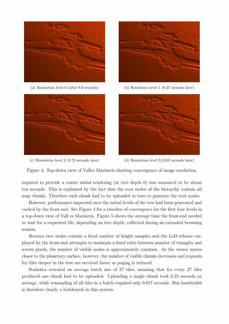
Figure 4: Top-down view of Valles Marineris showing convergence of image resolution.
required to provide a coarse initial rendering (at tree depth 0) was measured to be about
ten seconds. This is explained by the fact that the root nodes of the hierarchy contain all
map chunks. Therefore each chunk had to be uploaded in turn to generate the root nodes.
However, performance improved once the initial levels of the tree had been generated and
cached by the front-end. See Figure 4 for a timeline of convergence for the first four levels in
a top-down view of Vall es Marineris. Figure 5 shows the average time the front-end needed
to wait for a requested tile, depending on tree depth, collected during an extended browsing
session.
Because tree nodes contain a fixed number of height samples and the LoD scheme em-
ployed by the front-end attempts to maintain a fixed ratio between number of triangles and
screen pixels, the number of visible nodes is approximately constant. As the viewer moves
closer to the planetary surface, however, the number of visible chunks decreases and requests
for tiles deeper in the tree are serviced faster as paging is reduced.
Statistics revealed an average batch size of 27 tiles, meaning that for every 27 tiles
produced one chunk had to be uploaded. Uploading a single chunk took 0.23 seconds on
average, while resampling of all tiles in a batch required only 0.017 seconds. Bus bandwidth
is therefore clearly a bottleneck in this system.
Page 9
0
2
4
6
8
10
0 1 2 3 4 5 6 7 8
Avera
ge w
ait
tim
e[s
]
Node depth
Figure 5: Average delay between the front-end issuing a tile request and receiving the data.
Considering the speed-up factor established in 4.1, the CPU implementation would be
expected to require 0.47 seconds for processing a batch, which is still almost twice the time
needed by the GPU solution. The break-even point of similar performance would then be
expected at 13 tiles per batch.
Figure 6: Valles Marineris on Mars using both MOLA and HRSC datasets, composited on
the fly. Image resolution: 1920× 1200 pixels, 26.5 million triangles. Starting from an empty
cache, image quality converges within 30 seconds.
Page 10
5 Conclusion and future research possibilities
We have presented an efficient GPU-based approach to pre-process geo-referenced raster
maps for spherical terrain rendering. Furthermore, the algorithm was extended to an on-
line pre-processing scheme which enables interactive visualization of large datasets within
minutes.
Key to our approach is the assumption that the input data is resident in host RAM.
Constructing pre-filtered mipmaps of the input files on external storage as in [KLJ+09]
would increase startup time of the system but allow for out-of-core visualization of larger
datasets. Mipmap generation can be expected to be fast as it requires only linear I/O, as
opposed to construction of a quad tree database.
References
[BCK+11] Tony Bernardin, Eric Cowgill, Oliver Kreylos, Christopher Bowles, Peter Gold,
Bernd Hamann, and Louise Kellogg. Crusta: A new virtual globe for real-time
visualization of sub-meter digital topography at planetary scales. Computers &
Geosciences, 37(1):75–85, 2011.
[CGG+03] Paolo Cignoni, Fabio Ganovelli, Enrico Gobbetti, Fabio Marton, Federico Pon-
chio, and Roberto Scopigno. Planet–sized batched dynamic adaptive meshes
(p-bdam). In Proceedings IEEE Visualization, pages 147–155, Conference held
in Seattle, WA, USA, October 2003. IEEE Computer Society Press.
[DWS+97] Mark Duchaineau, Murray Wolinsky, David E. Sigeti, Mark C. Mille, Charles
Aldrich, and Mark B. Mineev-weinstein. Roaming terrain: Real-time optimally
adapting meshes. In IEEE Visualization, pages 81–88, 1997.
[GHB+05] K. M. Grski, E. Hivon, A. J. Banday, B. D. Wandelt, F. K. Hansen, M. Reinecke,
and M. Bartelmann. Healpix: A framework for high-resolution discretization
and fast analysis of data distributed on the sphere. The Astrophysical Journal,
622(2):759, 2005.
[GSP+10] K. Gwinner, F. Scholten, F. Preusker, S. Elgner, T. Roatsch, M. Spiegel,
R. Schmidt, J. Oberst, R. Jaumann, and C. Heipke. Topography of mars from
global mapping by hrsc high-resolution digital terrain models and orthoimages:
Characteristics and performance. Earth and Planetary Science Letters, 294(3-
4):506 – 519, 2010. ¡ce:title¿Mars Express after 6 Years in Orbit: Mars Geology
from Three-Dimensional Mapping by the High Resolution Stereo Camera (HRSC)
Experiment¡/ce:title¿.
Page 11
[KLJ+09] R. Kooima, J. Leigh, A. Johnson, D. Roberts, M. SubbaRao, and T.A. DeFanti.
Planetary-scale terrain composition. IEEE Transactions on Visualization and
Computer Graphics, 15(5):719–733, sept.-oct. 2009.
[Lev02] Joshua Levenberg. Fast view-dependent level-of-detail rendering using cached
geometry. In Proceedings of the conference on Visualization ’02, VIS ’02, pages
259–266, Washington, DC, USA, 2002. IEEE Computer Society.
[LH04] Frank Losasso and Hugues Hoppe. Geometry clipmaps: terrain rendering using
nested regular grids. In SIGGRAPH ’04: ACM SIGGRAPH 2004 Papers, pages
769–776, New York, NY, USA, 2004. ACM.
[LK10] Martin Lambers and Andreas Kolb. Dynamic terrain rendering. 3D Research,
1:1–8, 2010. 10.1007/3DRes.04(2010)01.
[PG07] Renato Pajarola and Enrico Gobbetti. Survey of semi-regular multiresolution
models for interactive terrain rendering. The Visual Computer, 23:583–605, 2007.
10.1007/s00371-007-0163-2.
[SZF+01] D. E. Smith, M. T. Zuber, H. V. Frey, J. B. Garvin, J. W. Head, D. O. Muhleman,
G. H. Pettengill, R. J. Phillips, S. C. Solomon, H. J. Zwally, W. B. Banerdt, T. C.
Duxbury, M. P. Golombek, F. G. Lemoine, G. A. Neumann, D. D. Rowlands,
O. Aharonson, P. G. Ford, A. B. Ivanov, C. L. Johnson, P. J. McGovern, J. B.
Abshire, R. S. Afzal, and X. Sun. Mars Orbiter Laser Altimeter: Experiment
summary after the first year of global mapping of Mars. Journal of Geophysical
Research, 106:23689–23722, October 2001.
[TKR+08] U. Thomas, F. Kurz, D. Rosenbaum, R. Mueller, and P. Reinartz. GPU-based
orthorectification of digital airborne camera images in real time. In Proceedings
of the XXI ISPRS Congress, 2008.