CIAL FEATURE POWER PLANT CONTROL Remote monitoring and control of advanced gas turbines by N. C. Corbett The commercial risks in providing services or products in the energy business require design engineers to provide low-risk solutions to arising problems that can be implemented in the shortest possible time. Maintaining plant availability is paramount and hence any solution must minimise prolonged exposure to the fault and prevent disruption to commercial operation. The tendency is to rely on existing knowledge; hence control system design features usually employ established techniques rather than incur undue risk. This article describes the engineering approach to providing a control system solution to a number of remote gas turbine installations that developed instabilities within their combustion systems. To fully understand the causes of these instabilities required a service introduction of both a practical and robust control solution to meet the customer expectations. In addition remote access to the installations to retrieve data and monitor the control system was essential in solving this problem. M ' anaging risk is essential before implement- ing any modification. Therefore employing unfamiliar techniques will undoubtedly ,incur higher risk; thus the tendency is to rely on existing knowledge. Hence control system design features usually employ established techniques. Providing an appropriate cost-effective solution within the high expectations of the customer whilst utilising existing resources does not readily permit the imple- mentation of new techniques without incurring significant risk. Any advanced techniques would require some form of technology acquisition programme to demonstrate that the required level of understanding has been obtained, and that it has been thoroughly evaluated by subjecting it to rigorous validation and verification processes requiring resource and incurring cost. It should be noted that the costs incurred are not necessarily those to find the solution, but also the time it takes to implenient the solution, as the penalties in failing to meet commer- cial availability guarantees can be extremely high. The area where there is an immediate benefit of applying advanced control techniques at lower risk, as it would not have a direct impact on the operation of the engine, is intelligent data analysis tools. These can be used to aid the understanding of further problems and predict when changes occur from which solutions can be worked on before the failure occurs. Low-emission combustion To meet the challenge of the low-emission require- ments imposed by regulating authorities, gas turbine manufacturers have introduced new combustion and engine control systems into their product range. Without exception the new combustors have been based on the technology of pre-mix lean burn to uniformly mix the fuel with the air to produce lower combustion temperatures and avoid producing high concentrations of oxides of nitrogen, NOx. These are inevitably of a staged design requiring the accurate scheduling and distribution of fuel to be performed by the engine's control system. The Rolls-RoyceIndustrial ICE 211 and Trent engines are both high-pressure ratio gas turbines, derived from their respective aero counterparts. They are each equipped with similar pre-mixed lean burn staged combustors designated dry low emission (DLE). In each of these engines both the emissions levels and COMPUTING & CONTROL ENGINEERING JOURNAL APRIL 2001
Transcript
CIAL FEATURE POWER PLANT CONTROL
Remote monitoring and control of advanced gas turbines by N. C. Corbett
The commercial risks in providing services or products in the energy business require design engineers to provide low-risk solutions to arising problems that can be implemented in the shortest possible time. Maintaining plant availability is paramount and hence any solution must minimise prolonged exposure to the fault and prevent disruption to commercial operation. The tendency is to rely on existing knowledge; hence control system design features usually employ established techniques rather than incur undue risk. This article describes the engineering approach to providing a control system solution to a number of remote gas turbine installations that developed instabilities within their combustion systems. To fully understand the causes of these instabilities required a service introduction of both a practical and robust control solution to meet the customer expectations. In addition remote access to the installations to retrieve data and monitor the control system was essential in solving this problem.
M ' anaging risk is essential before implement- ing any modification. Therefore employing unfamiliar techniques will undoubtedly ,incur higher risk; thus the tendency is to
rely on existing knowledge. Hence control system design features usually employ established techniques.
Providing an appropriate cost-effective solution within the high expectations of the customer whilst utilising existing resources does not readily permit the imple- mentation of new techniques without incurring significant risk. Any advanced techniques would require some form of technology acquisition programme to demonstrate that the required level of understanding has been obtained, and that it has been thoroughly evaluated by subjecting it to rigorous validation and verification processes requiring resource and incurring cost. It should be noted that the costs incurred are not necessarily those to find the solution, but also the time it takes to implenient the solution, as the penalties in failing to meet commer- cial availability guarantees can be extremely high.
The area where there is an immediate benefit of applying advanced control techniques at lower risk, as it would not have a direct impact on the operation of the
engine, is intelligent data analysis tools. These can be used to aid the understanding of further problems and predict when changes occur from which solutions can be worked on before the failure occurs.
Low-emission combustion To meet the challenge of the low-emission require-
ments imposed by regulating authorities, gas turbine manufacturers have introduced new combustion and engine control systems into their product range. Without exception the new combustors have been based on the technology of pre-mix lean burn to uniformly mix the fuel with the air to produce lower combustion temperatures and avoid producing high concentrations of oxides of nitrogen, NOx. These are inevitably of a staged design requiring the accurate scheduling and distribution of fuel to be performed by the engine's control system.
The Rolls-Royce Industrial ICE 211 and Trent engines are both high-pressure ratio gas turbines, derived from their respective aero counterparts. They are each equipped with similar pre-mixed lean burn staged combustors designated dry low emission (DLE). In each of these engines both the emissions levels and
COMPUTING & CONTROL ENGINEERING JOURNAL APRIL 2001
Fig. 1 Rolls-Royce RB211 DLE combustor
availability will be a function of the performance of the engine’s control system.
Development testing As gas turbine engine designs increasingly incor-
porate new technology to meet the demands ol new requirements and challenges, it is inevitable that unpredicted operating conditions will occur that will lead to an unexpected response or reaction. Therefore providing solutions to situations that arise when the engines enter service is somewhat inevitable, as no matter how thorough the verification testing that has been performed, it cannot always be exhaustive because of development time and cost constraints.
Wide-ranging gas fuel composition and the multi- staged combustion process add complexity to the validation requirements. Indeed some conditions may not show up during prototype testing and only surface when there are certain combinations of events, climate, wear and tear and operating duty. This was the case when under certain operating conditions, within the combustor, an acoustic wave was generated that
produced a resonant reaction with the combustion system structure.
COMPUTING & CONTIWL ENGINEERING JOURNAL APRIL 2001
Combustion amplified noise Industrial gas turbines have universally had problems
with combustion amplified pressure oscillations (com- bustion instability or noise) in premix lean burn combustors. Under specific conditions a resonant frequency achieves sufficient amplitude to cause severe damage to the combustor. As the emissions are reduced to lower levels, by achieving better uni€ormity of fuel and air distribution and a larger percentage of the air is used in the combustion process, then these amplitudes have the potential to become greater especially at high pressure ratios. Small changes in either ambient conditions or fuel quality appear to cause noise amplitudes to become unacceptable.
Remote data monitoring As gas turbine installations become more advanced
then there is an increasing reliance on the simultaneous operation of a plethora of subsystem equipment. These
PLANT CONTROL
demand that advanced methods are employed to monitor was when flame cxtinction at weak fuel concentration the installation and its sophisticated equipment to conditions was approached during engine development simplify the data that is presented to the operator. test. At this point in time there was a signiiicant margin
Although acquiring and trending of traditional data between this noise region and the normal combustor serves its purpose and has identified operating temperatures on all KB211 DLE problems in the past, the use of more The use of engines. The first aero derivative engine was sophisticated techniques can benefit both installed in Starbuck, Washington, USA, and single and multi engine fleet operators to remote achieved 7200 hours before it was removed manage their business more effectively. access for inspection and evaluation. There had Methods that can identify optimisation or been no combustion related problems differentiate between deterioration and the reported, during which time the NOs faults can help maximise the time between gas turbine emissions had been maintained at thc planned outages as well as predict the manufacturer factory pass-off test of 25 vppm throughout appropriate time to perform the the period. Subsequent engines have since maintenance. The methods employed can to obtain vast achieved more than 25000 hours with no equally be applied to the engine and any of its dependent equipment and subsystems, thus providing data on how well the
amounts of combustion related problems.
0%-site eunlunlion data equipment is performing.
The use ol remote access to installations enables the gas turbine manufacturer to obtain and observe vast amounts of data, which is probably the first time they have had access to operational data rather than shop test.
Industrial RB211 DLE The RR211-24C, rated at 24 757k\V, fitted with the DLIS
combustor entered service in November 1994. Although some combustion generated acoustic noise was detected during engine development, it only occurred at very low combustor primary zone temperatures; the margin remained sufficient not to affect the operation of the engine. Thc only operational occurrence of the response
It was during this in-field evaluation period that remote access to engine data variables and historical recording was performed within the engine’s control system, and it was essential for the engineering team in the UK to acquire data and support the introduction of the lirst engine. Although remote monitoring had been pcriormed before, this usually and almost exclusively was restricted to measured engine parameters, speed, temperature and pressures, and was totally acquired by the site operator. The unit in Washington provided access to a comprehensive database of both measured ancl derived variables within both gas turbine and unit control systems. As well as maintaining historical data on all installation
Fig. 2 Acoustic control schematic
dynamic + pressure
transducer acoustic interface unit
secondary control valve
COMPUTING Sr CONTROL ENGINEERING JOURNAL APRIL 2001
6
Y
Cl 1 5 0 - control bias I z 4 Q
E 3
g 2 2 1
- m
4.4
c 0
0 10 20 30 40 50 60 70 80 90
instances had continued and resulted in fatigue cracking.
combustion system was not itnmediatcly forthcoming, and required extensive
The design solution to the engine and
engineering effort to understand the reasons and causes, and then produce a practicable solutioii which would work.
Subsequent eiiginc and combustion testing designed to simulate the operating conditions of these cngines during certain low ambient conditions revealed a serious forced vibration of the discharge nozzle and the support caused by largc pressure fluct-
I time, s
-
2.80 2.78 2.76 5 2.74 2.72
Q 2.70 9 2.68 ‘L 2.66
2.64 2.62 2.60
0 2 4 6 8 10 12 14 16 18
time, s
instrumentation and equipment it enabled online analysis of engine and systcm performance including emissions reporting.
l?B21 I -24G During 1996, an upratcd enginc, the RR211-24G
(28 2001tW), was introduced Again the usual vcrification and validation testing indicated that the engine had not shown any undue areas of risk or that it would react any differently to thc earlier -24C rated cngines. The uprate adopted the turbine standard lrom the aero IU3211-524G programme, which enabled the power to increase with an improvement in thermal efficiency by increasing the turbine inlet tcniperaturc arid increasing the combustor air inlet conditions (pressure, temperature, air and luel
During the 1996197 winter a small number of installations in Canada, equipped with RB211-24G engines, uncxpectedly exhibited problems with thcir respective combustion systems. In each case the combustor discharge nozzles and the supporting
rates).
Fig. 3 Control scheme response
Erficalion of combustion data Understanding of the problem and the events leading
to the failures was aided by the retrieval of historical site data, which is continuous. Thc conditions in the UI< were not ideal lor verification testing, as it was difficult to recreate the exact problems to the extent that persisted in Canada. Therefore establishing a link to acquire operational data on these sites was essential whercby continuous collection ol information relating to the prcssure fluctuations was fundamental for correlating test and site response data. It was important to establish a method by which data could be retricved should any engines have been modified in any way again to corrclate the response with test data.
In-sewice engiiw inodification Each of the in-service engines was required to be
equipped with the same dynamic pressurc transducer that had been used during the development testing. These were fitted to measure the fluctuations in pressure in the combustor outer casing annulus or in the torch
COMI’UTING 6i CONTROL ENGINEERING JOURNAL APRIL 2001
PLANT CONTROL
1970
1950
1930
1910
1890
1870
1850
1830
1810
1790
With the in-service engines in Canada modified data was retrieved initially for a period ol one month and at every 4 minutes the data was plotted. During this period the ambient temperature varied between +7 and -28°C where the maximum noise was observed to occur at -9°C.
-
5 psi
y, I lyp( -
- psi
3 psi
low power E
Maintainivag unit availability The gas turbine operator had contracts to fulfil that
required full load availability of the equipment, par- ticularly throughout the winter in Canada. Therefore an immediate solution was required to maintain engine availability without exposing it to any further damage whilst the engine was still equipped with the existing combustor hardware.
Control system In order to meet the customer needs to maintain the
availability of their fleet of RB211-24G engines, a control system design solution was introduced to mitigate the risk of prolonging exposure of these engines to the combustor pressure fluctuations. There were a number of versions of control solutions developed. This was to incorporate features to meet the various customer requirements and expectations, and as mitigation of risk as the techniques became established and confidence was obtained from both the customer and engineering management.
Evolution of the conlrol sclzeme The control system improvement is to maintain the
longevity of the engine. The control scheme detects the onset of the combustor instability through the monitoring of broadband pressure fluctuation responses that have been correlated for combustor stress using strain gauges at various locations on the combustor and ancillary parts
from engine test. When the pressure fluctuations exceed a preestablished threshold, the control system is required to take the appropriate actions.
Initial mle-based scheme The Rolls-Royce design philosophy is to arrange
combustion processes in series (Fig. I) whereby the primary stage is designed to create combustion stability. Hence the temperature of this zone is held constant at the minimum margin above weak extinction.
Although the control system is required to maintain constant temperature within the primary stage of the combustor over the operating range, there is correlation of the two dominant bands with combustion temperature. The control scheme is required to respond by re- distributing the fuel rate to the combustor stages by adjusting the temperature of the primary stage whenever it detects and confirms fluctuations of pressure. Redistri- bution between the respective stages is accomplished without any need to change the load or power output (Fig. 2).
As the signal provided was a broadband response, the control system uses a set of rules to distinguish which of the dominant combustor frequencies was present. The control system applies a controlled small step response of the fuel rate to test which o€ the dominant frequencies was present. It then awaits the response of the combustor to adjustment (Fig. 3).
If the fluctuations are conlirmed to decrease as a result of the adjustment, then the control scheme continues to adjust the primary temperature until a satisfactory level is achieved. However, if the fluctuations are confirmed to increase as a result ol the adjustment, then the control scheme returns the combustion temperature to the pre- adjusted level, and then proceeds to adjust the primary
CP103 EMS peak-to-peak, psi
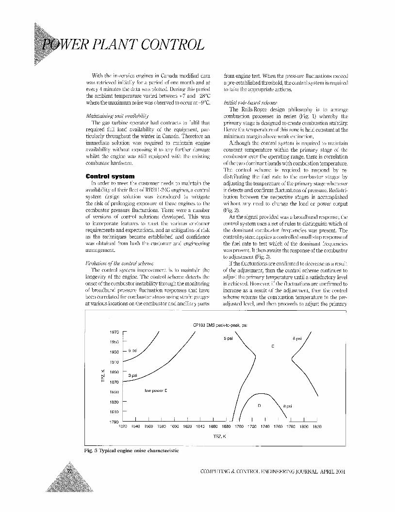
Fig. 5 Typical engine noise characteristic
COMPUTING & CONTROL ENGINEERING JOURNAL APRIL 2001
temperature in the opposing direction until satisfactory level is achieved.
amplitude of the pressure fluctuations, then the control scheme changes the permitted load a€ the engine until an acceptable level is reached.
response from the spectrum analyser it was then possible to directly compare data collected in the Field and on the
In the event that neither direction reduces the test stand. All engines under investigation on the test stand have their dynamic pressure signals output to both the control system modified card and the spectrum analyser to maintain the correlation of data.
Dynamic pressure sigtzal conditioning D e v e l o p " testing The sensors used in the development test cell were 'The control solution was tested using a combination of
output to specialised laboratory equipment, i.e. spectrum engine test vehicles and models, of which the latter were analysers, which provided detailed response data across improved as more data was acquired. Experimental the frequency spectrum and were interpreted by the testing was minimised requiring only final validation of experienced engineers analysing the a control scheme or equipment developed. responses. This methodology was not The implementation of the monitoring and practical for the in-service engines and did The increased control schemes was completed in a very not allow synchronising of the response amount of short period of time, and was ready when with engine and installation variables, the engine re-entered commercial which was essential in correlating and data improved operation. The increased amount of data assimilation of the data to understand the problem.
To correlate the data with the engine variables the control system received the changes within schemes. charge signal lrom the pressure transducer, either directly from the sensor
the knowledge base to identify
improved the knowledge base to identify changes occurring within the engine and provided data to improve the initial control
the engine Revised rub-based scheme or pre-processed. The most cost and time effective method chosen was to adapt one of the control system's vibration input modules, by selecting a broadband filter to remove other engine fundamental responses.
The characteristics of the noise signal are somewhat erratic and not of a predictable form. However, a simple first-order filter was sufficient and provided a stable signal that could be correlated with the average amplitude of noise activity, and increased as the responses became more regular and intense (Fig. 4).
With this closely correlating to the timc integrated
There are two combustor dominant frequencies, designated D and E, which
occur when operating in premix lean burn, whose frequency range changes slightly with engine conditions. One dominant frequency is associated with the primary premix operation, whilst the other is associated with the secondary fuelling. At full power on near IS0 ambient clays the noise amplitudes are low. Fig. 5 shows a typical noise map; however, there is notable engine-to-engine variability.
In this version, the control scheme has knowledge of the two dominant frequency band responses. In addition
COMPUTING Kr CONTROL ENGINEERING JOURNAL APRIL 2001
to the broadband signal modified vibration input cards provide a narrow band filtered signal of each of the dominant frequency 1) and E band. Therefore with this information the control can immediately take the appropriate action without determining the response to small distribution changes.
Additionally with this scheme when both dominant frequency bands co-exist, the control scheme can adjust the primary stage temperature to minimise the pressure fluctuation simultaneously by €inding the point where both are minimised together.
Maintaiaing uai2 load In the event that the both signals cannot be minimised
simultaneously, again the control system will auto- matically change the permitted load of the engine until an acceptable level is attained. However, for installations where availalility of load is critical rather than reduce load the control system automatically changes the mode of combustion in the primary stage from premix to diffusion whilst maintaining premix in the subsequent stages. Although there is an increase in the emissions of NOs it is still signilicantly less than emitted from conventional combustion engines.
The control system will oiily permit returning to premix in the primary stage when conditions previously confirmed as satisfactory can be sustained. The control scheme retains and updates the combustor operating conditions and detects when these have altered, i.e. engine load or combustion inlet conditions.
Irduslrial Trent Similar problems have occurred an the industrial
Trent; this time there are three resonant frequencies bccause it is equipped with a three-stage combustion system. The noise problems are managed on the Trent by transferring fuel between the three stages to avoid the noise islands.
Status update Since the original problem manifested itself, a
successful design change has been incorporated into production engines. This has provided a significant reduction in the combustor pressure fluctuations. Fig. 6 shows the increased area of low amplitude responses between the two dominant characteristics compared with Fig. 5. The control scheme discussed is retained as a basic design feature to assure continuous low-amplitude operation whilst monitoring any changes in character- istic that occur. Over half a million running hours have now been accumulated on the RB211 L)LK engine.
Conclusion It is important to note that- the majority of these gas
turbine installations are unmanned and more often than not located in remote and isolated areas. Therefore the engine control system has total authority of control
and is both the eyes and ears for the engine and its installation. The step-by-step approach each time increased the level of authority that the control system could take in administering preventive action without endangering the engine. This not only permitted the installations to remain operational but also prevented exposure to any further distress or outage for main- tenance whilst a permanent solution could be devised.
Significant in-service changes are required to gas turbine plant as this example has illustrated. The process of providing validated change whilst maintaining customer satislaction is a delicate balance. The acquisition of quality data irom real installations is invaluable. The use of simulation with confirmatory engine testing has given cost-efkctive solutions.
This example has in many ways pioneered our activities to use real-time data in predictive algorithms to maximise availability of the in-service fleet.
We are using computational intelligent tools to automatically analyse data and identify abnormally belore major (expensive) mechanical damage can occur. These tools are being developed to analyse both abiiorinalities with the gas turbine hardware and the complex control system hardware that is necessary to control emissions.
Acknowledgments
and Mike Todman of Kolls-Ibyce plc for their a in providing information and reviewing this art
Bibliography 1 I’ANAILJI K N, I!, and MONGIA I-IUI<AM, C.: ‘Combustion
instalility c tics nf industrial engine dry low emission combustion systems’, 34th A IAA/ASME/SA I’IASER Joint Propulsion Confercncc, Cleveland Ohio 13th-15th July 1998 AIAA98-3379
The author wishes to thank Norman Lines, Jeff Willis
D. A.: ‘Mcchanical design and dcvclopinent of the IZT3211 dry low emissions engine’, ASMIC International Gas Turbine and Aernengine Congress ;incl I‘xposition, Cincinnati, Ohio, 24th-27th May 1993, ASMR/IGTI 93-G‘T-245
4 CORl3IT’L; N. C., and IdNI N. H: ‘Control requirements for the RI321 1 low emission combu n system’, ASMI’ International (>as Turbine and Acroeng-ine Congress and Exposition, Cincinnati, Ohio, 24th-27th Map 1993, ASILIE/I(;TI 93-G‘r-12
5 SCAIUNCI, T., and HAI.l’NI J. I,.: ‘Industrial Trent combustor- combustor noise characlerisl ic’, ASME International Gas Turbine and Arrocngiiie Congress and Exposition , Indianapolis, Indiana, 7th-10th June 1999, ASMl<ilGTI 9 X T 9
6 MORAN, J. A., COIUE’IT, N. C., TOI)I\IIAN, M. ‘1:: ‘The dry low emission industrial Avon,’ ASMI<; Intcrnational Gas ‘I’tirbine and Aeroengine Congress and I‘xposition , Indianapolis, Iiitliana, 7th.lOth June 1999, ASMEiIGTI 99.G‘T-Yl
7 HUI3I3AI~L), S., ancl I)OPVI,ING, A. I!: ‘Acoustic instabilities in pi-einix Iiurners’, 4th AIAAiCEAS Aeroacoustics Conference Toulousc France, 2nd-4th Julie 1998 ,AIAA\-98-2272
61 IEB: 2001
The author is with Rolls-lbyce I’owcr Engineering, Coventry CV7 9JR, UIC
COMPUTING & CONTROL ENGINEERING JOURNAL APRIL 2001