38
© Westell Technologies Part # 030-300637 Rev. A WESTELL.COM INSTALLATION GUIDE Remote RMX-3200 Intelligent Site Management Device Installation Guide
© Westell Technologies
Part # 030-300637 Rev. A
WESTELL.COM
INSTA
LLATION
GU
IDE
Remote RMX-3200Intelligent Site Management
Device
Installation Guide
WESTELL.COM
Page 0
Remote RMX-3200 Installation Guide
1-800-377-8766
Copyright © 2015 by Westell Technologies®. All Rights Reserved. Westell, Kentrox® and Optima Management System® are registered trademarks of Westell. All other names are trademarks of their respective owners.
Information is correct at time of publication and is subject to change without notice. Contact Westell in Aurora, Illinois, to verify current product information. Westell Inc. is an Equal Opportunity/Affirmative Action employer.
Westell Technologies750 North CommonsAurora, IL 60504 USA
Toll Free: (800) 377-8766International: +1 (630) 375-4950
Fax: +1 (630) 375-4931
Remote RMX-3200 Installation Guide
Page 1
Remote RMX-3200Intelligent Site Management Device
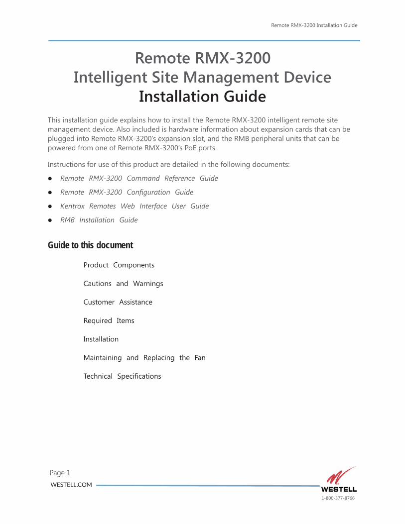
Installation GuideThis installation guide explains how to install the Remote RMX-3200 intelligent remote site management device. Also included is hardware information about expansion cards that can be plugged into Remote RMX-3200’s expansion slot, and the RMB peripheral units that can be powered from one of Remote RMX-3200’s PoE ports.
Instructions for use of this product are detailed in the following documents:
Remote RMX-3200 Command Reference Guide
Remote RMX-3200 Configuration Guide
Kentrox Remotes Web Interface User Guide
RMB Installation Guide
Guide to this document
Product Components
Cautions and Warnings
Customer Assistance
Required Items
Installation
Maintaining and Replacing the Fan
Technical Specifications
WESTELL.COM
1-800-377-8766
Remote RMX-3200 Installation GuideProduct Components
Page 2
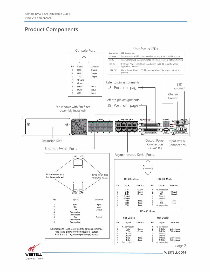
Product Components
Input PowerConnections
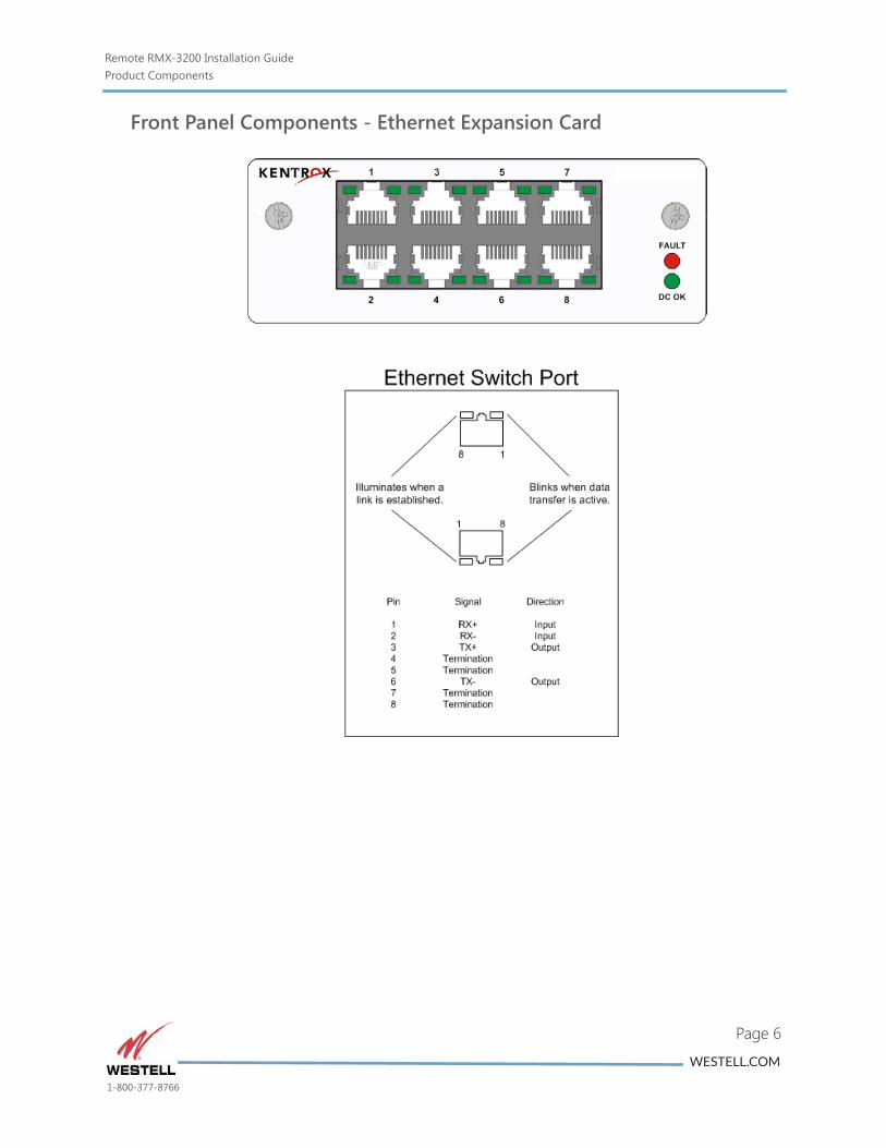
Ethernet Switch Ports
Chassis Ground
8 1
Pin12345678
SignalRTSDTRTXDGroundGroundRXDDSRCTS
DirectionOutputOutput
Input
Output
InputInput
Console Port
Refer to pin assignments
J8 Port on page 4
Refer to pin assignments
J9 Port on page 4
ESD Ground
LED Description
Summary alarm LED: Illuminated when any point is in alarm state
Hardware failure LED: Illuminated when processor is not functioning
DC Input Power LED: Illuminated when valid DC Input Power is applied to the unit
Alarm Power Health LED: Illuminated when 24V power output is present
LED Status
APR OK
DC OK
ALARM
Unit Status LEDs
FAULT
Output PowerConnection (+24VDC)
Fan (shown with fan filter assembly installed)
Expansion Slot
Asynchronous Serial Ports
WESTELL.COM
1-800-377-8766
Remote RMX-3200 Installation GuideProduct Components
Page 3
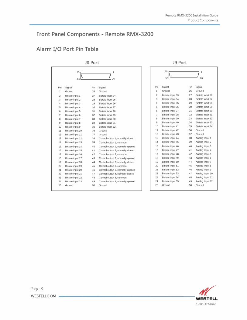
Front Panel Components - Remote RMX-3200
Alarm I/O Port Pin Table
J9 PortJ8 Port
22 Bistate input 21
Pin1
2345678
SignalGround
Bistate input 1Bistate input 2Bistate input 3Bistate input 4Bistate input 5Bistate input 6Bistate input 7
9 Bistate input 810 Bistate input 911 Bistate input 1012 Bistate input 1113 Bistate input 12
25 1
50 26
14
15161718192021
Bistate input 13
Bistate input 14Bistate input 15Bistate input 16Bistate input 17Bistate input 18Bistate input 19Bistate input 20
23 Bistate input 222425
Bistate input 23Ground
Pin26
27282930313233
SignalGround
Bistate input 24Bistate input 25Bistate input 26Bistate input 27Bistate input 28Bistate input 29Bistate input 30
34 Bistate input 3135 Bistate input 3236 Ground37 Ground38 Control output 1, normally closed39
40414243444546
Control output 1, normally openedControl output 2, normally closedControl output 2, commonControl output 2, normally openedControl output 3, normally closedControl output 3, commonControl output 3, normally opened
4748
Control output 4, normally closedControl output 4, common
4950
Control output 4, normally openedGround
Control output 1, common
21 Bistate input 53
Pin1
2345678
SignalGround
Bistate input 33Bistate input 34Bistate input 35Bistate input 36Bistate input 37Bistate input 38Bistate input 39
9 Bistate input 4010 Bistate input 4111 Bistate input 4212 Bistate input 4313 Bistate input 44
25 1
50 26
14
15161718192021
Bistate input 45
Bistate input 46Bistate input 47Bistate input 48Bistate input 49Bistate input 50Bistate input 51Bistate input 52
23 Bistate input 542425
Bistate input 55Ground
Pin26
27282930313233
SignalGround
Bistate input 56Bistate input 57Bistate input 58Bistate input 59Bistate input 60Bistate input 61Bistate input 62
34 Bistate input 6335 Bistate input 6436 Ground37 Ground38 Analog Input 139
40414243444546
Analog Input 2
Analog Input 3Analog Input 4Analog Input 5Analog Input 6Analog Input 7Analog Input 8Analog Input 9
4748
Analog Input 10Analog Input 11
4950
Analog Input 12Ground
WESTELL.COM
1-800-377-8766
Remote RMX-3200 Installation GuideProduct Components
Page 4
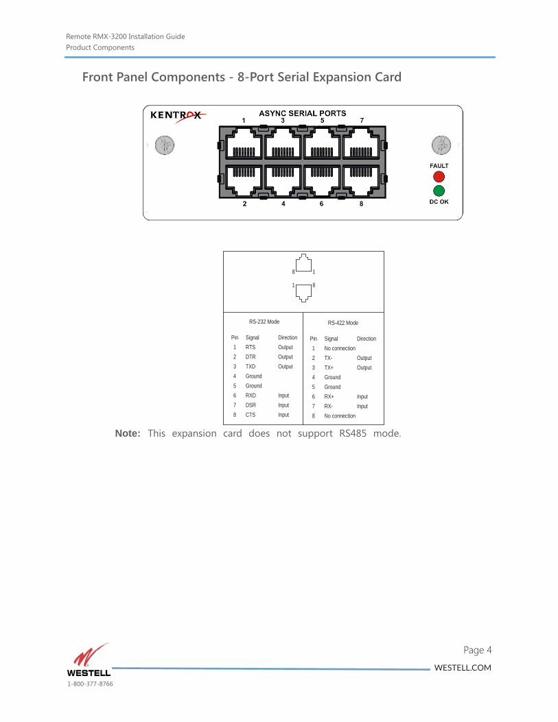
Front Panel Components - 8-Port Serial Expansion Card
Note: This expansion card does not support RS485 mode.
8 1
1 8
RS-232 Mode
Pin12345678
SignalRTSDTRTXDGroundGroundRXDDSRCTS
DirectionOutputOutput
Input
RS-422 Mode
Pin12345678
SignalNo connectionTX-TX+GroundGroundRX+RX-No connection
Direction
OutputOutput
InputInput
Output
InputInput
WESTELL.COM
1-800-377-8766
Remote RMX-3200 Installation GuideProduct Components
Page 5
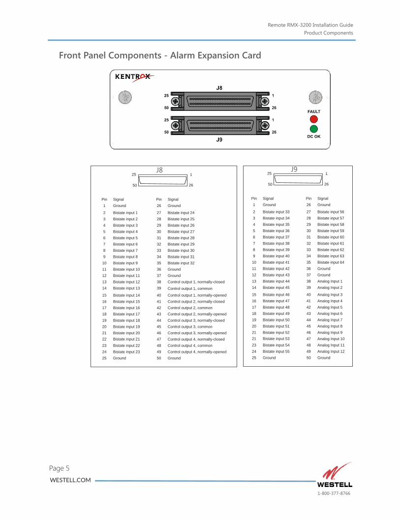
Front Panel Components - Alarm Expansion Card
21 Bistate input 53
Pin1
2345678
SignalGround
Bistate input 33Bistate input 34Bistate input 35Bistate input 36Bistate input 37Bistate input 38Bistate input 39
9 Bistate input 4010 Bistate input 4111 Bistate input 4212 Bistate input 4313 Bistate input 44
25 1
50 26
14
15161718192021
Bistate input 45
Bistate input 46Bistate input 47Bistate input 48Bistate input 49Bistate input 50Bistate input 51Bistate input 52
23 Bistate input 542425
Bistate input 55Ground
Pin26
27282930313233
SignalGround
Bistate input 56Bistate input 57Bistate input 58Bistate input 59Bistate input 60Bistate input 61Bistate input 62
34 Bistate input 6335 Bistate input 6436 Ground37 Ground38 Analog Input 139
40414243444546
Analog Input 2
Analog Input 3Analog Input 4Analog Input 5Analog Input 6Analog Input 7Analog Input 8Analog Input 9
4748
Analog Input 10Analog Input 11
4950
Analog Input 12Ground
22 Bistate input 21
Pin1
2345678
SignalGround
Bistate input 1Bistate input 2Bistate input 3Bistate input 4Bistate input 5Bistate input 6Bistate input 7
9 Bistate input 810 Bistate input 911 Bistate input 1012 Bistate input 1113 Bistate input 12
25 1
50 26
14
15161718192021
Bistate input 13
Bistate input 14Bistate input 15Bistate input 16Bistate input 17Bistate input 18Bistate input 19Bistate input 20
23 Bistate input 222425
Bistate input 23Ground
Pin26
27282930313233
SignalGround
Bistate input 24Bistate input 25Bistate input 26Bistate input 27Bistate input 28Bistate input 29Bistate input 30
34 Bistate input 3135 Bistate input 3236 Ground37 Ground38 Control output 1, normally-closed39
40414243444546
Control output 1, normally-openedControl output 2, normally-closedControl output 2, commonControl output 2, normally-openedControl output 3, normally-closedControl output 3, commonControl output 3, normally-opened
4748
Control output 4, normally-closedControl output 4, common
4950
Control output 4, normally-openedGround
Control output 1, common
J8 J9
WESTELL.COM
1-800-377-8766
Remote RMX-3200 Installation GuideProduct Components
Page 6
Front Panel Components - Ethernet Expansion Card
WESTELL.COM
1-800-377-8766
Remote RMX-3200 Installation GuideProduct Components
Page 7
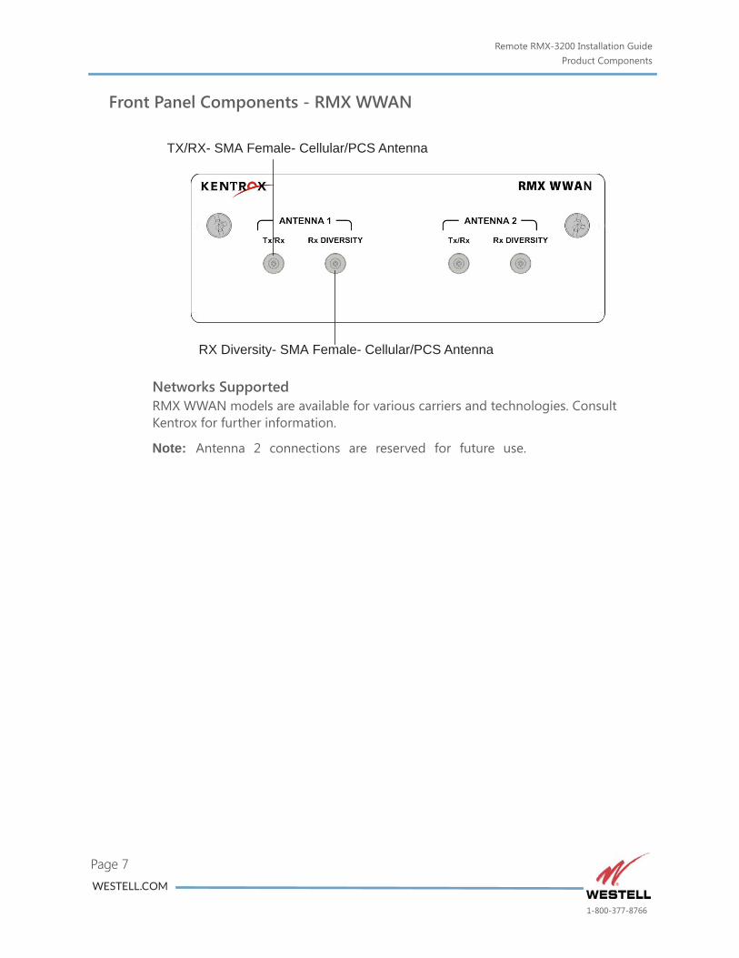
Front Panel Components - RMX WWAN
Networks SupportedRMX WWAN models are available for various carriers and technologies. Consult Kentrox for further information.
Note: Antenna 2 connections are reserved for future use.
TX/RX- SMA Female- Cellular/PCS Antenna
RX Diversity- SMA Female- Cellular/PCS Antenna
WESTELL.COM
1-800-377-8766
Remote RMX-3200 Installation GuideProduct Components
Page 8
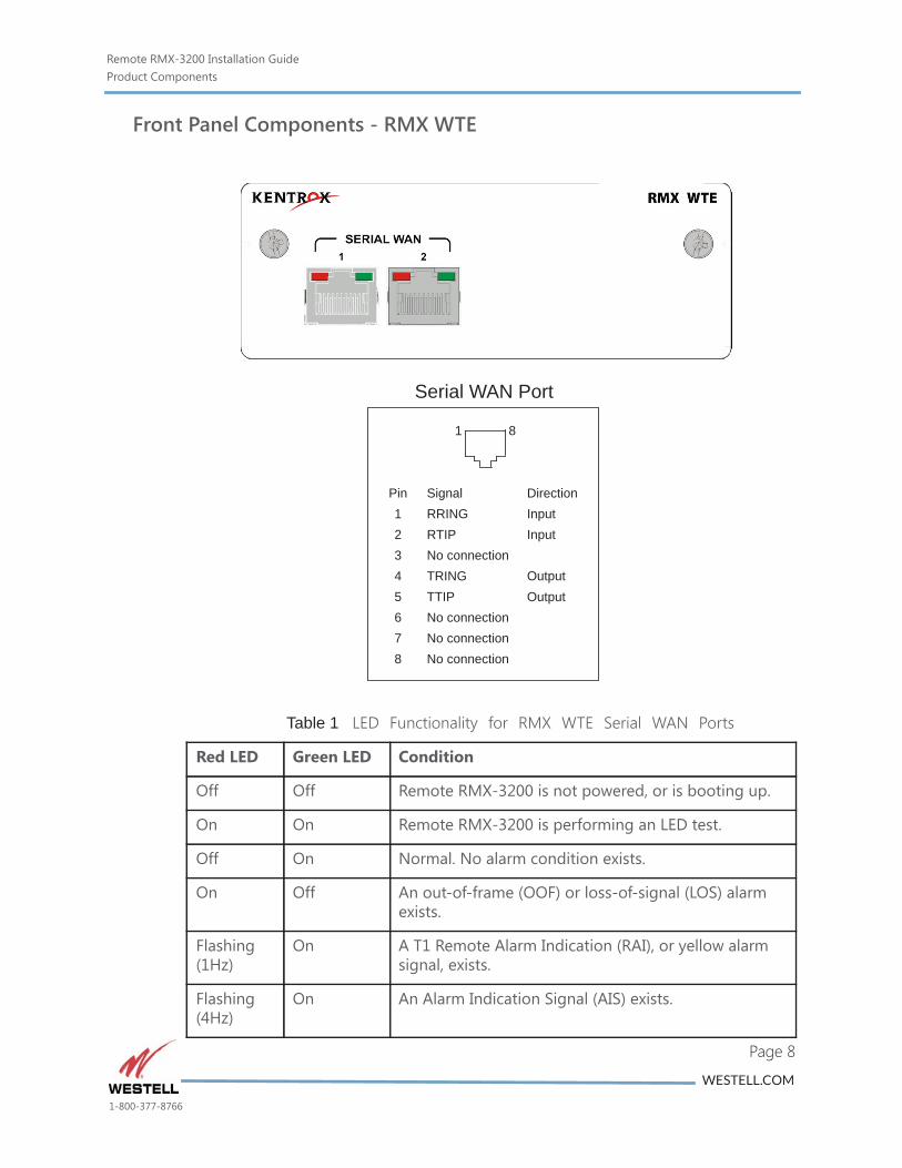
Front Panel Components - RMX WTE
Table 1 LED Functionality for RMX WTE Serial WAN Ports
Red LED Green LED Condition
Off Off Remote RMX-3200 is not powered, or is booting up.
On On Remote RMX-3200 is performing an LED test.
Off On Normal. No alarm condition exists.
On Off An out-of-frame (OOF) or loss-of-signal (LOS) alarm exists.
Flashing (1Hz)
On A T1 Remote Alarm Indication (RAI), or yellow alarm signal, exists.
Flashing (4Hz)
On An Alarm Indication Signal (AIS) exists.
1 8
Pin12345678
SignalRRINGRTIPNo connectionTRINGTTIPNo connectionNo connectionNo connection
DirectionInputInput
OutputOutput
Serial WAN Port
WESTELL.COM
1-800-377-8766
Remote RMX-3200 Installation GuideProduct Components
Page 9
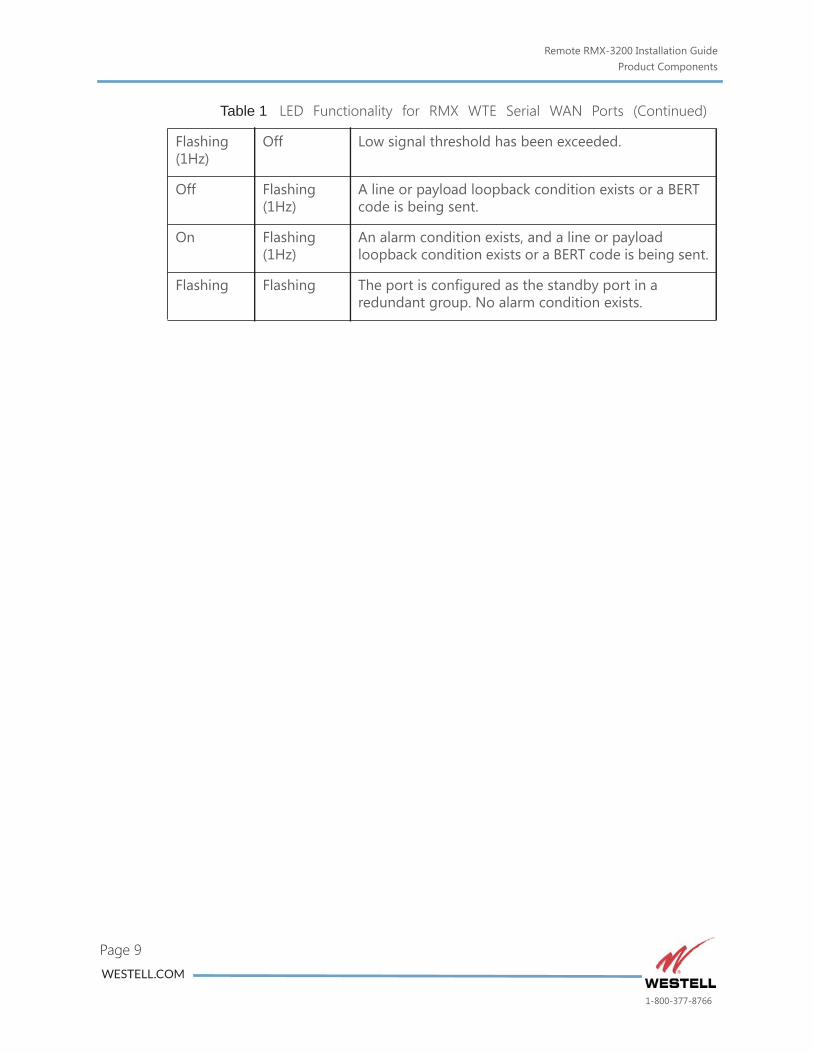
Flashing (1Hz)
Off Low signal threshold has been exceeded.
Off Flashing (1Hz)
A line or payload loopback condition exists or a BERT code is being sent.
On Flashing (1Hz)
An alarm condition exists, and a line or payload loopback condition exists or a BERT code is being sent.
Flashing Flashing The port is configured as the standby port in a redundant group. No alarm condition exists.
Table 1 LED Functionality for RMX WTE Serial WAN Ports (Continued)
WESTELL.COM
1-800-377-8766
Remote RMX-3200 Installation GuideProduct Components
Page 10
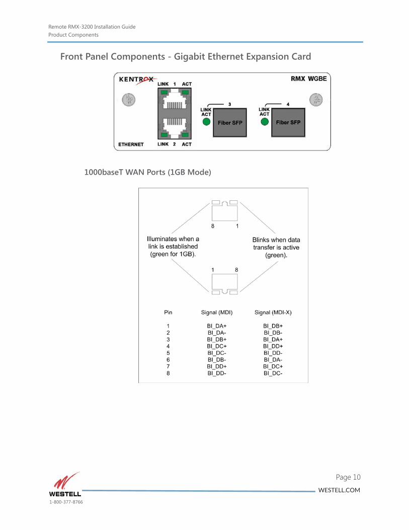
Front Panel Components - Gigabit Ethernet Expansion Card
1000baseT WAN Ports (1GB Mode)
WESTELL.COM
1-800-377-8766
Remote RMX-3200 Installation GuideProduct Components
Page 11
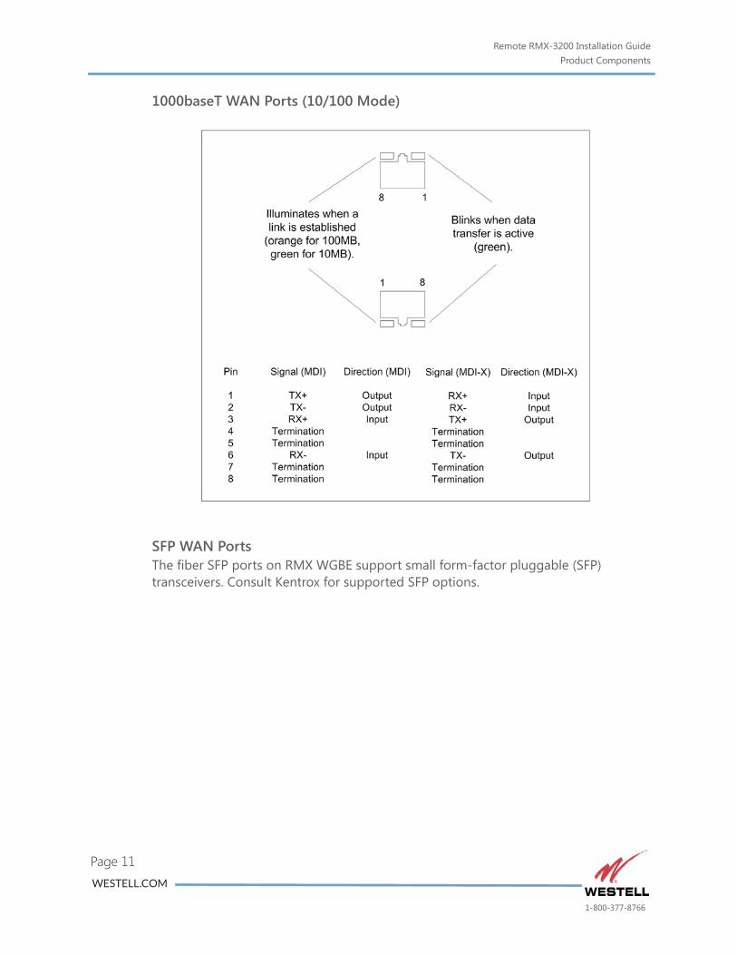
1000baseT WAN Ports (10/100 Mode)
SFP WAN PortsThe fiber SFP ports on RMX WGBE support small form-factor pluggable (SFP) transceivers. Consult Kentrox for supported SFP options.
WESTELL.COM
1-800-377-8766
Remote RMX-3200 Installation GuideCautions and Warnings
be a
e of
the
.
Page 12
Cautions and Warnings
Grounding and Electrical Safety
CAUTION: Kentrox equipment and its peripherals contain electrostatic sensitive components. Proper handling, shipping, and storage precautions must be exercised.
Installation
CAUTION: For Kentrox equipment to operate safely and correctly, there must safety ground strap between the equipment ground bolts and the office ground.
Environment
CAUTION: In the event that Remote RMX-3200 has been subjected to adverseenvironmental conditions, a service inspection of Remote RMX-3200 should be made to ensure safe operation.
Lithium Batteries
CAUTION: Risk of explosion if battery is replaced by an incorrect type. Disposused batteries according to the instructions.
Internal Cooling Fan
CAUTION: The internal fan on Remote RMX-3200 is not user-serviceable. Shouldfan fail to operate, customers may either contact Westell Customer Assistance to return the Remote RMX-3200 device for repair or replacement; or follow the enclosed instructions for Maintaining and Replacing the Fan. Estimated mean time to disconnect your Remote RMX-3200 from the network and replace it with a new device is one hour.
Restricted Access Locations
CAUTION: The Remote RMX-3200 is for use in restricted access locations only
WESTELL.COM
1-800-377-8766
Remote RMX-3200 Installation GuideCautions and Warnings
te
ible
Page 13
NEBS Compliance Requirements
CAUTION: The intra-building ports, including Ethernet, asynchronous, and discreinput ports, of the equipment or subassembly are suitable for connection to intra-building or unexposed wiring or cabling only. The intra-building ports of the equipment or subassembly MUST NOT be metallically connected to interfaces that connect to the OSP or its wiring. These interfaces are designed for use as intra-building interfaces only (Type 2 or Type 4 ports as described in GR-1089) and require isolation from the exposed OSP cabling. The addition of Primary Protectors is not sufficient protection in order to connect these interfaces metallically to OSP wiring.
The intra-building ports, including Ethernet, asynchronous, and discrete input ports, of the equipment or subassembly must use shielded intra-building cabling/wiring that is grounded at both ends.
Laser Radiation
LASER DANGER: The WGBE expansion card uses Class IIIb laser devices. Invislaser radiation is present when the optic connectors are open. Always avoid direct or scattered exposure to the beam when servicing or installing customer cables. Also avoid exposure from receive cables connected to any laser device.
FCCThe Federal Communications Commission has set limits for emitted radio interference, and Remote RMX-3200 is constructed with this electromagnetic interference (EMI) limitation in mind. Remote RMX-3200 is classified under FCC regulations as a Class A device, that is, a device for use in commercial environments and not in residential areas. This device has been tested and shown to comply with the following FCC rule: Part 15 Subpart J. Operation of this equipment in a residential area may cause interference to radio and TV reception, requiring the user to take whatever steps are necessary to correct the interference.
Information is available from the FCC describing possible corrective actions. To maintain low EMI levels, we suggest that you use only metal connectors and shielded cable grounded to the frame.
Remote RMX-3200 complies with 47 CFR, Part 68 of the rules. On the top of Remote RMX-3200 is a label that contains, among other information, the certification number and ringer equivalence number (REN) for this equipment. If requested, this information must be provided to the telephone company.
If the terminal equipment Remote RMX-3200 uses causes harm to the telephone network, the telephone company will notify you in advance that temporary
WESTELL.COM
1-800-377-8766
Remote RMX-3200 Installation GuideCautions and Warnings
Page 14
discontinuance of service may be required. But if advance notice is not practical, the telephone company will notify the customer as soon as possible. Also, you will be advised of your right to file a complaint with the FCC if you believe it is necessary.
The telephone company may make changes in its facilities, equipment, operations, or procedures that could affect the operation of the equipment. If this happens, the telephone company will provide advance notice in order for you to make necessary modifications to maintain uninterrupted service.
If trouble is experienced with Remote RMX-3200, for repairs or warranty information, please contact Kentrox, Inc. If the equipment is causing harm to the telephone network, the telephone company may request that you disconnect the equipment until the problem is resolved.
Specifications are subject to change without notice.
WESTELL.COM
1-800-377-8766
Remote RMX-3200 Installation GuideCustomer Assistance
Page 15
Customer AssistanceAll customers, partners, and resellers who have a valid Westell Support and Services Agreement have complete access to the technical support resources.
Pre-sales Support
Westell offers pre-sales technical support from 9 a.m. to 5 p.m. Eastern time, Monday - Friday. Representatives are standing by to assist with customer account information and product ordering and answer questions regarding Westell products and solutions.
Phone number: 800-377-8766, option 1
Before you call or email
Before you contact Westell for assistance, please have the following information available:
The versions of hardware and software you are currently running
The error number and exact wording of any messages that appeared on your screen
What happened and what you were doing when the problem occurred
How you tried to solve the problem
Email Technical Support
Email support is available. You may send email at any time during the day; however, responses will be provided only during normal business hours, in accordance with your Service and Support Agreement.
To contact Technical Support, send email to:
Telephone Technical Support
Available to qualified Westell customers or partners who have not been able to resolve their technical issue by using our online services. To qualify for support, you must have a valid Support and Services Agreement.
Phone number: 800-377-8766, option 2
Normal Business Hours: 8 a.m. to 6 p.m. Eastern time
After-Hours Support: Available to qualified customers who are experiencing service-affecting outages that cannot wait until the next business day. To qualify for after-hours support, you must have a valid 24x7 Support and Services Agreement. Call the number above, option 2, and follow the prompts for after-hours service.
WESTELL.COM
1-800-377-8766
Remote RMX-3200 Installation GuideCustomer Assistance
Page 16
Product Documentation
You can also access and view the most current versions of Kentrox product documentation on our web site at:
http://www.westell.com
WESTELL.COM
1-800-377-8766
Remote RMX-3200 Installation GuideRequired Items
Page 17
Required Items
Tools #2 Phillips screwdriver
Small flathead screwdriver (Phoenix 3 mm, recommended)
3/32 in. slotted screwdriver
Crimping tool
Wire cutter
Wire stripper
Grounding wrist strap
Voltmeter, DC range
PC with terminal emulation software such as Procomm
10mm nut driver
Materials Four screws, sized to fit your rack
Wire for input power connections (16 AWG solid or stranded insulated)
Wire for ground connection (14 AWG, copper conductor)
Ground lugs for rack or other earth ground
Antioxidant
Various required rack cables and cable assemblies
(For fan replacement only) Westell Part # 543-000015 (fan)
(For fan replacement only) Westell Part # 501-000672 (fan filter assembly)
WESTELL.COM
1-800-377-8766
Remote RMX-3200 Installation GuideInstallation
Page 18
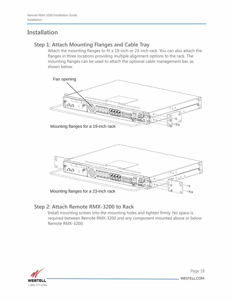
Installation
Step 1: Attach Mounting Flanges and Cable TrayAttach the mounting flanges to fit a 19-inch or 23-inch rack. You can also attach the flanges in three locations providing multiple alignment options to the rack. The mounting flanges can be used to attach the optional cable management bar, as shown below.
Step 2: Attach Remote RMX-3200 to RackInstall mounting screws into the mounting holes and tighten firmly. No space is required between Remote RMX-3200 and any component mounted above or below Remote RMX-3200.
Mounting flanges for a 19-inch rack
Fan opening
Mounting flanges for a 23-inch rack
WESTELL.COM
1-800-377-8766
Remote RMX-3200 Installation GuideInstallation
Page 19
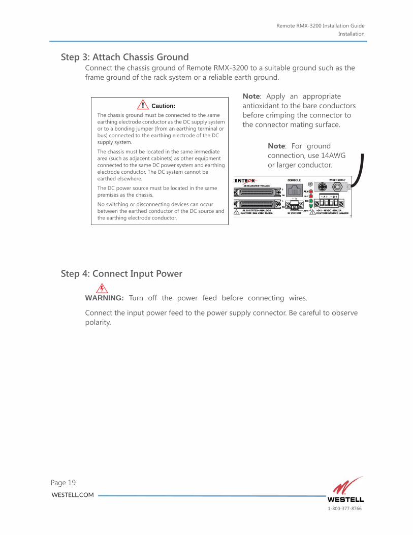
Step 3: Attach Chassis GroundConnect the chassis ground of Remote RMX-3200 to a suitable ground such as the frame ground of the rack system or a reliable earth ground.
Step 4: Connect Input Power
WARNING: Turn off the power feed before connecting wires.
Connect the input power feed to the power supply connector. Be careful to observe polarity.
Note: Apply an appropriate antioxidant to the bare conductors before crimping the connector to the connector mating surface.
The chassis ground must be connected to the same earthing electrode conductor as the DC supply system or to a bonding jumper (from an earthing terminal or bus) connected to the earthing electrode of the DC supply system.
The chassis must be located in the same immediate area (such as adjacent cabinets) as other equipment connected to the same DC power system and earthing electrode conductor. The DC system cannot be earthed elsewhere.
The DC power source must be located in the same premises as the chassis.
No switching or disconnecting devices can occur between the earthed conductor of the DC source and the earthing electrode conductor.
Caution:
Note: For ground connection, use 14AWG or larger conductor.
WESTELL.COM
1-800-377-8766
Remote RMX-3200 Installation GuideInstallation
Page 20
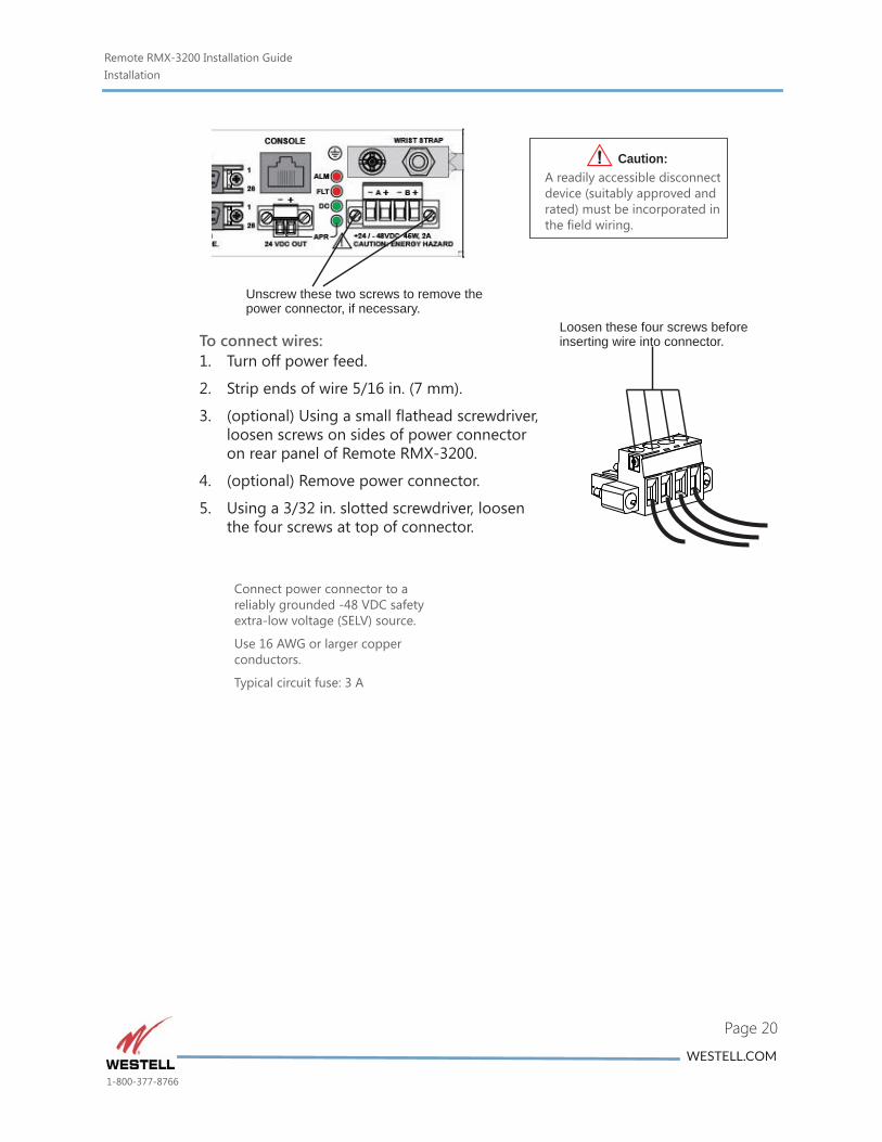
Unscrew these two screws to remove thepower connector, if necessary.
Loosen these four screws beforeinserting wire into connector.
Connect power connector to a reliably grounded -48 VDC safety extra-low voltage (SELV) source.
Use 16 AWG or larger copper conductors.
Typical circuit fuse: 3 A
A readily accessible disconnect device (suitably approved and rated) must be incorporated in the field wiring.
Caution:
To connect wires:1. Turn off power feed.
2. Strip ends of wire 5/16 in. (7 mm).
3. (optional) Using a small flathead screwdriver, loosen screws on sides of power connector on rear panel of Remote RMX-3200.
4. (optional) Remove power connector.
5. Using a 3/32 in. slotted screwdriver, loosen the four screws at top of connector.
WESTELL.COM
1-800-377-8766
Remote RMX-3200 Installation GuideInstallation
Page 21
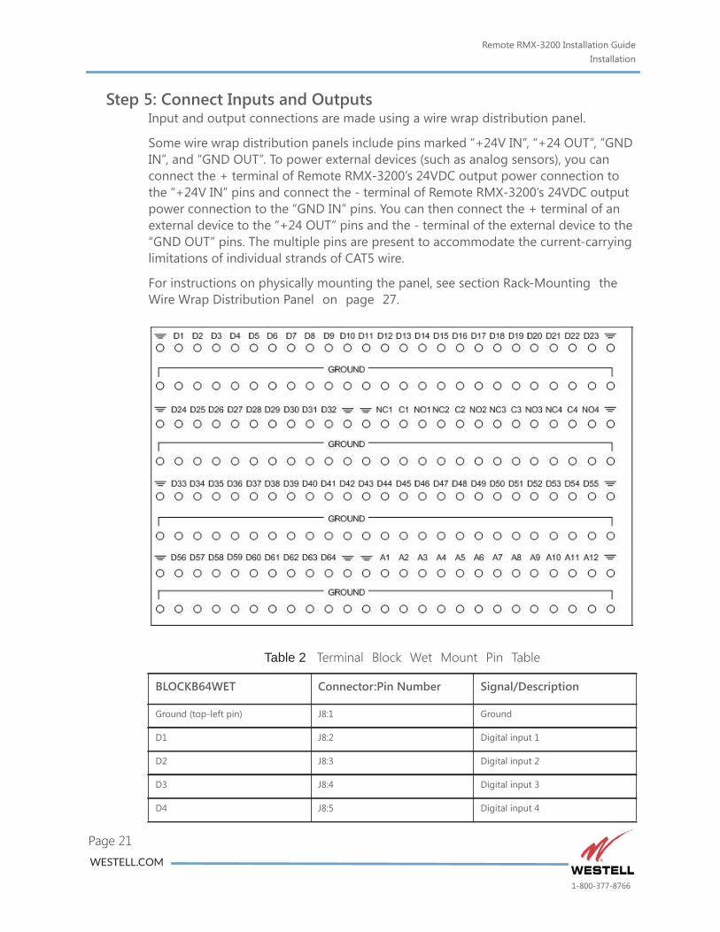
Step 5: Connect Inputs and OutputsInput and output connections are made using a wire wrap distribution panel.
Some wire wrap distribution panels include pins marked “+24V IN”, “+24 OUT”, “GND IN”, and “GND OUT”. To power external devices (such as analog sensors), you can connect the + terminal of Remote RMX-3200’s 24VDC output power connection to the “+24V IN” pins and connect the - terminal of Remote RMX-3200’s 24VDC output power connection to the “GND IN” pins. You can then connect the + terminal of an external device to the “+24 OUT” pins and the - terminal of the external device to the “GND OUT” pins. The multiple pins are present to accommodate the current-carrying limitations of individual strands of CAT5 wire.
For instructions on physically mounting the panel, see section Rack-Mounting the Wire Wrap Distribution Panel on page 27.
Table 2 Terminal Block Wet Mount Pin Table
BLOCKB64WET Connector:Pin Number Signal/Description
Ground (top-left pin) J8:1 Ground
D1 J8:2 Digital input 1
D2 J8:3 Digital input 2
D3 J8:4 Digital input 3
D4 J8:5 Digital input 4
WESTELL.COM
1-800-377-8766
Remote RMX-3200 Installation GuideInstallation
Page 22
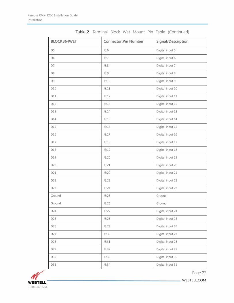
D5 J8:6 Digital input 5
D6 J8:7 Digital input 6
D7 J8:8 Digital input 7
D8 J8:9 Digital input 8
D9 J8:10 Digital input 9
D10 J8:11 Digital input 10
D11 J8:12 Digital input 11
D12 J8:13 Digital input 12
D13 J8:14 Digital input 13
D14 J8:15 Digital input 14
D15 J8:16 Digital input 15
D16 J8:17 Digital input 16
D17 J8:18 Digital input 17
D18 J8:19 Digital input 18
D19 J8:20 Digital input 19
D20 J8:21 Digital input 20
D21 J8:22 Digital input 21
D22 J8:23 Digital input 22
D23 J8:24 Digital input 23
Ground J8:25 Ground
Ground J8:26 Ground
D24 J8:27 Digital input 24
D25 J8:28 Digital input 25
D26 J8:29 Digital input 26
D27 J8:30 Digital input 27
D28 J8:31 Digital input 28
D29 J8:32 Digital input 29
D30 J8:33 Digital input 30
D31 J8:34 Digital input 31
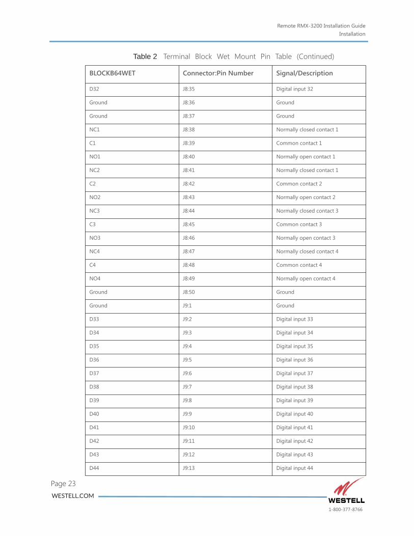
Table 2 Terminal Block Wet Mount Pin Table (Continued)
BLOCKB64WET Connector:Pin Number Signal/Description
WESTELL.COM
1-800-377-8766
Remote RMX-3200 Installation GuideInstallation
Page 23
D32 J8:35 Digital input 32
Ground J8:36 Ground
Ground J8:37 Ground
NC1 J8:38 Normally closed contact 1
C1 J8:39 Common contact 1
NO1 J8:40 Normally open contact 1
NC2 J8:41 Normally closed contact 1
C2 J8:42 Common contact 2
NO2 J8:43 Normally open contact 2
NC3 J8:44 Normally closed contact 3
C3 J8:45 Common contact 3
NO3 J8:46 Normally open contact 3
NC4 J8:47 Normally closed contact 4
C4 J8:48 Common contact 4
NO4 J8:49 Normally open contact 4
Ground J8:50 Ground
Ground J9:1 Ground
D33 J9:2 Digital input 33
D34 J9:3 Digital input 34
D35 J9:4 Digital input 35
D36 J9:5 Digital input 36
D37 J9:6 Digital input 37
D38 J9:7 Digital input 38
D39 J9:8 Digital input 39
D40 J9:9 Digital input 40
D41 J9:10 Digital input 41
D42 J9:11 Digital input 42
D43 J9:12 Digital input 43
D44 J9:13 Digital input 44
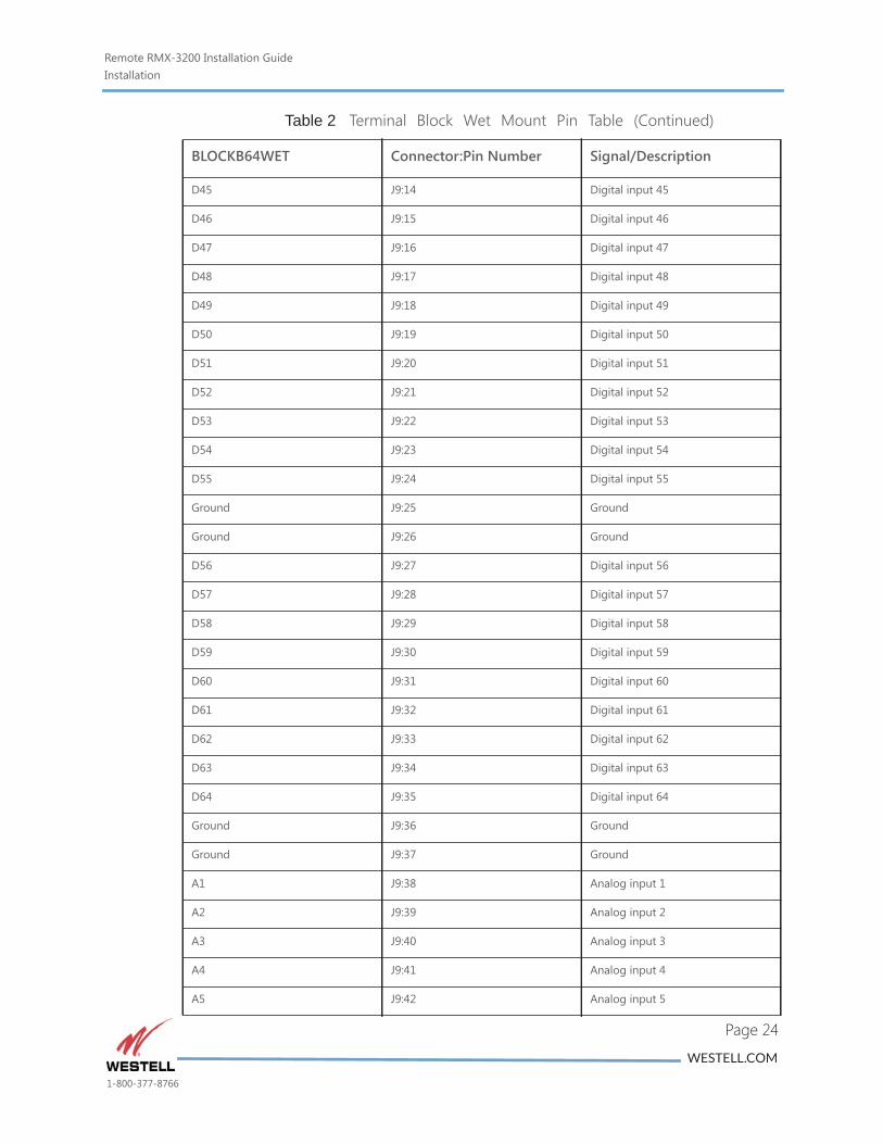
Table 2 Terminal Block Wet Mount Pin Table (Continued)
BLOCKB64WET Connector:Pin Number Signal/Description
WESTELL.COM
1-800-377-8766
Remote RMX-3200 Installation GuideInstallation
Page 24
D45 J9:14 Digital input 45
D46 J9:15 Digital input 46
D47 J9:16 Digital input 47
D48 J9:17 Digital input 48
D49 J9:18 Digital input 49
D50 J9:19 Digital input 50
D51 J9:20 Digital input 51
D52 J9:21 Digital input 52
D53 J9:22 Digital input 53
D54 J9:23 Digital input 54
D55 J9:24 Digital input 55
Ground J9:25 Ground
Ground J9:26 Ground
D56 J9:27 Digital input 56
D57 J9:28 Digital input 57
D58 J9:29 Digital input 58
D59 J9:30 Digital input 59
D60 J9:31 Digital input 60
D61 J9:32 Digital input 61
D62 J9:33 Digital input 62
D63 J9:34 Digital input 63
D64 J9:35 Digital input 64
Ground J9:36 Ground
Ground J9:37 Ground
A1 J9:38 Analog input 1
A2 J9:39 Analog input 2
A3 J9:40 Analog input 3
A4 J9:41 Analog input 4
A5 J9:42 Analog input 5
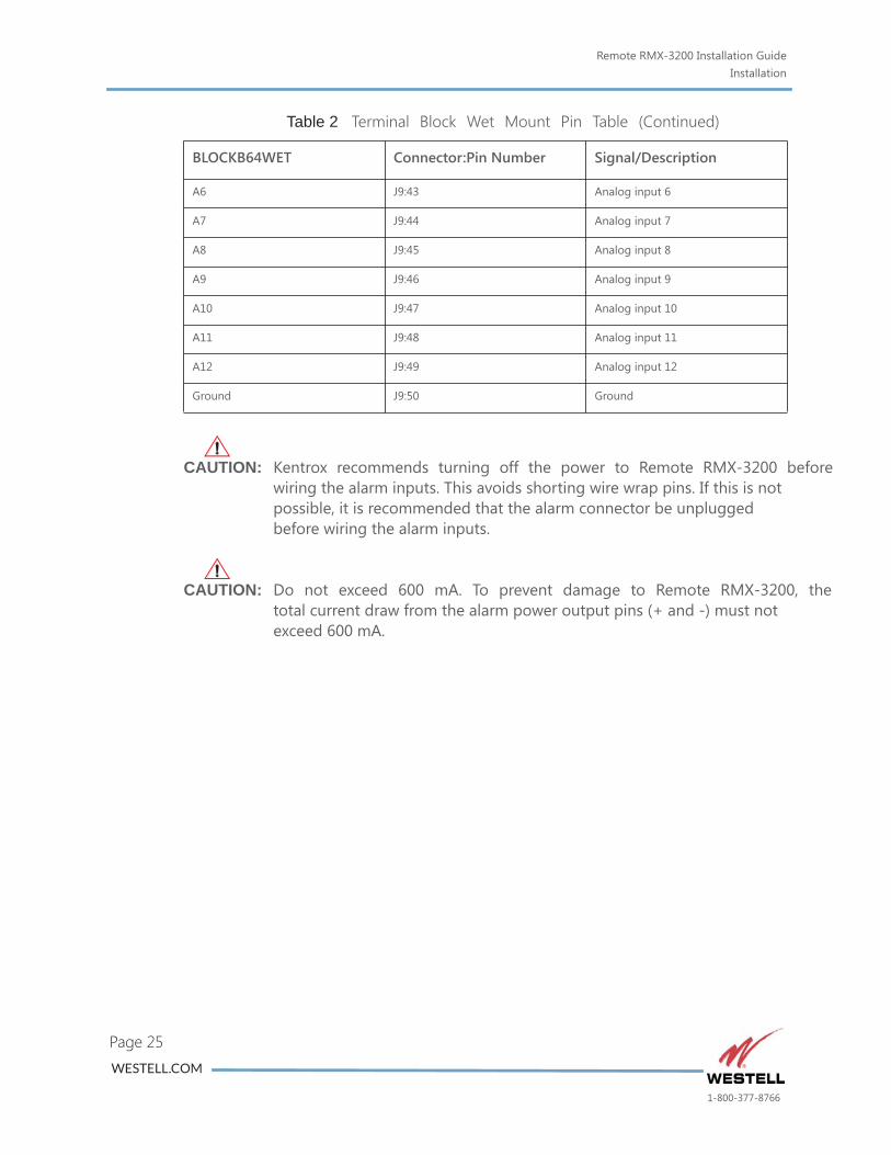
Table 2 Terminal Block Wet Mount Pin Table (Continued)
BLOCKB64WET Connector:Pin Number Signal/Description
WESTELL.COM
1-800-377-8766
Remote RMX-3200 Installation GuideInstallation
fore
the
Page 25
CAUTION: Kentrox recommends turning off the power to Remote RMX-3200 bewiring the alarm inputs. This avoids shorting wire wrap pins. If this is not possible, it is recommended that the alarm connector be unplugged before wiring the alarm inputs.
CAUTION: Do not exceed 600 mA. To prevent damage to Remote RMX-3200, total current draw from the alarm power output pins (+ and -) must not exceed 600 mA.
A6 J9:43 Analog input 6
A7 J9:44 Analog input 7
A8 J9:45 Analog input 8
A9 J9:46 Analog input 9
A10 J9:47 Analog input 10
A11 J9:48 Analog input 11
A12 J9:49 Analog input 12
Ground J9:50 Ground
Table 2 Terminal Block Wet Mount Pin Table (Continued)
BLOCKB64WET Connector:Pin Number Signal/Description
WESTELL.COM
1-800-377-8766
Remote RMX-3200 Installation GuideInstallation
nted
Page 26
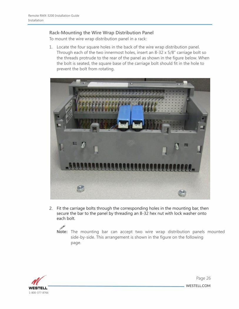
Rack-Mounting the Wire Wrap Distribution PanelTo mount the wire wrap distribution panel in a rack:
1. Locate the four square holes in the back of the wire wrap distribution panel. Through each of the two innermost holes, insert an 8-32 x 5/8" carriage bolt so the threads protrude to the rear of the panel as shown in the figure below. When the bolt is seated, the square base of the carriage bolt should fit in the hole to prevent the bolt from rotating.
2. Fit the carriage bolts through the corresponding holes in the mounting bar, then secure the bar to the panel by threading an 8-32 hex nut with lock washer onto each bolt.
Note: The mounting bar can accept two wire wrap distribution panels mou
side-by-side. This arrangement is shown in the figure on the following page.
WESTELL.COM
1-800-377-8766
Remote RMX-3200 Installation GuideInstallation
r
Page 27
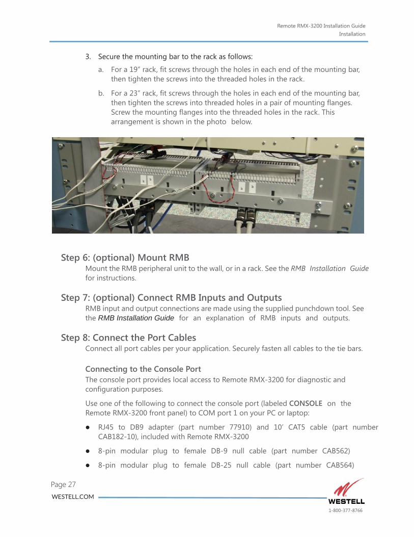
3. Secure the mounting bar to the rack as follows:
a. For a 19” rack, fit screws through the holes in each end of the mounting bar, then tighten the screws into the threaded holes in the rack.
b. For a 23” rack, fit screws through the holes in each end of the mounting bar, then tighten the screws into threaded holes in a pair of mounting flanges. Screw the mounting flanges into the threaded holes in the rack. This arrangement is shown in the photo below.
Step 6: (optional) Mount RMBMount the RMB peripheral unit to the wall, or in a rack. See the RMB Installation Guide for instructions.
Step 7: (optional) Connect RMB Inputs and OutputsRMB input and output connections are made using the supplied punchdown tool. See the RMB Installation Guide for an explanation of RMB inputs and outputs.
Step 8: Connect the Port CablesConnect all port cables per your application. Securely fasten all cables to the tie bars.
Connecting to the Console PortThe console port provides local access to Remote RMX-3200 for diagnostic and configuration purposes.
Use one of the following to connect the console port (labeled CONSOLE on the Remote RMX-3200 front panel) to COM port 1 on your PC or laptop:
RJ45 to DB9 adapter (part number 77910) and 10’ CAT5 cable (part numbeCAB182-10), included with Remote RMX-3200
8-pin modular plug to female DB-9 null cable (part number CAB562)
8-pin modular plug to female DB-25 null cable (part number CAB564)
WESTELL.COM
1-800-377-8766
Remote RMX-3200 Installation GuideInstallation
ove.
as a
cable
r
umber
umber
)
ove.
rds.
ing
Page 28
Note: Your specific application may require a cable other than those listed ab
Connecting to an Asynchronous Serial PortAsynchronous serial ports allow terminal devices with asynchronous serial ports (such as PCs, NEs, and asynchronous modems) to connect to Remote RMX-3200.
Use one of the following cables to connect one of the asynchronous serial ports (labeled ASYNC SERIAL PORTS on the front panel) to an external device, such modem:
8-pin modular plug to 8-pin modular plug rollover DTE to DTE null RS-232(part number CAB213)
Male DB-25 to 8-pin modular plug DTE to DCE straight cable (part numbeCAB214) for temporary console access
Female DB-25 to 8-pin modular plug DTE to DTE null RS-232 cable (part nCAB564) for temporary console access
Female DB-9 to 8-pin modular plug DTE to DTE null RS-232 cable (part nCAB562) for temporary console access
All serial interfaces other than temporary console access must use shielded cable for FCC compliance.
Connecting to a Serial WAN PortSerial WAN ports (provided by the optional RMX WTE WAN module) allow you to connect Remote RMX-3200 to a WAN either directly or through another device, such as a DSX panel or a T1 or E1 router. When Remote RMX-3200 is connected to a WAN, you can access other networks.
Use one of the following cables to connect one of the serial WAN ports (labeled SERIAL WAN on the RMX WTE front panel) to another device on a WAN:
8-pin modular plug to 8-pin modular plug null cable (part number CAB502
CSU/DSU modular plug to 8-pin modular plug cable (part number CAB228)
Note: Your specific application may require a cable other than those listed ab
Note: Use shielded cable to ensure compliance with applicable emission standa
Note: Serial WAN connections made through RMX WTE are rated for intrabuildconnections. They are not rated for surges that may result from interbuilding connections (for example, lightning strikes).
Connecting to an Ethernet PortThe switched Ethernet ports allow you to connect Ethernet-capable devices to Remote RMX-3200 and allow you to connect Remote RMX-3200 to a LAN. The optional RMX WGBE module adds two Gigabit Ethernet (1000baseT) ports.
WESTELL.COM
1-800-377-8766
Remote RMX-3200 Installation GuideInstallation
e on
rt
mber
ove.
age
X-
Page 29
Use one of the following cables to connect one of the switched Ethernet ports (labeled ETHERNET on the Remote RMX-3200 front panel) to an Ethernet devicyour network:
8-pin modular plug to 8-pin modular plug crossover 10/100BaseT cable (panumber CAB542)
8-pin modular plug to 8-pin modular plug straight 100BaseT cable (part nuCAB182)
Note: Your specific application may require a cable other than those listed ab
When connecting to one of RMX WGBE’s Gigabit Ethernet ports, use CAT6 cable for optimal performance.
Connecting to a Fiber SFP PortFiber SFP ports (provided by the optional RMX WGBE module) support small form-factor pluggable (SFP) transceivers. Consult Kentrox for supported SFP options.
Connecting to a Digital InputYou can connect a digital input on Remote RMX-3200 to a contact or relay output on a monitored device, such as a magnetic door switch. When an event occurs, such as a door opening or closing, the switch opens or closes. Remote RMX-3200 responds by generating an event.
Use the Kentrox wet block kit (part number BLOCKB64WET) to make digital input connections to Remote RMX-3200. Consult Kentrox for other distribution options.
Connecting to an Analog InputYou can connect an analog input on Remote RMX-3200 to a 4 to 20 mA current loop or a 0 to 10 VDC transducer, which converts a physical input to a current or voltoutput. For example, the physical input could be the temperature or voltage which is then converted into a current between 4 mA and 20 mA or 0 to 10 VDC. Remote RM3200 can be configured to generate events when current thresholds are crossed, or to report input current values at intervals.
Use the Kentrox wet block kit (part number BLOCKB64WET) to make analog input connections to Remote RMX-3200. Consult Kentrox for other distribution options.
Connecting to a Relay OutputYou can connect a relay output on Remote RMX-3200 to control a device.
Use the Kentrox wet block kit (part number BLOCKB64WET) to make relay output connections to Remote RMX-3200. Consult Kentrox for other distribution options.
Connecting RMX-3200 to RMB (optional)
WESTELL.COM
1-800-377-8766
Remote RMX-3200 Installation GuideInstallation
Page 30
Use a standard CAT5 Ethernet cable (such as Kentrox part number CAB182-10) to connect one of RMM-1400’s PoE-enabled Ethernet ports to the Ethernet port on RMB.
CAUTION: Kentrox recommends disconnecting the Ethernet PoE cable to RMB before wiring inputs and outputs in order to avoid electrical shorts.
Step 9: (optional) Configure an IP AddressConfiguring the IP address allows Remote RMX-3200 to be accessed remotely.
To configure the IP address:
1. Set the terminal emulation software on the PC or terminal emulator to 9600 baud, no parity, eight data bits, one stop bit, and XON/XOFF flow control.
2. Use a terminal cable to connect the PC or terminal to the Remote RMX-3200 console port and press ENTER.
3. At the prompt, enter admin. This is the default login.
4. At the password prompt, enter password. This is the default password.
5. At the command prompt enter config interface bridge switch ip address, followed by the IP address and subnet mask. For example:
config interface bridge switch ip address 10.34.64.222 255.255.255.0
6. At the command prompt, enter config ip route default and the default gateway address. For example:
config ip route default 172.10.11.222
WESTELL.COM
1-800-377-8766
Remote RMX-3200 Installation GuideMaintaining and Replacing the Fan
mers X-
l
Page 31
Maintaining and Replacing the Fan
Fan Inspection and MaintenanceWestell recommends inspecting the fan built into Remote RMX-3200 every six months. The inspector should make sure the fan is operating, the opening is not obstructed, and the filter is clean. Clean or replace the filter if needed (see instructions below). If the fan is making noise, replacement is advisable.
Cleaning the Fan FilterWestell recommends cleaning or replacing the fan filter every three to six months. Fan filters need to be replaced at least every two to three years to ensure media reliability and eliminate residual dust buildup and subsequent airflow resistance.
1. Remove the filter from the housing on the front of Remote RMX-3200 prior to initiating cleaning.
2. The filter may be cleaned using slightly compressed air, a vacuum, mild detergent, and/or clean water. If cleaning with compressed air or vacuum only, the dry filter can be reinstalled immediately.
3. If cleaning with water:
The filter should be completely dry before reinstallation.
Use only a mild detergent, such as dishwashing liquid, if degreasing is necessary. Avoid using harsh solvents or cleaning agents.
4. Also clean the filter housing and the filter mounting location on Remote RMX-3200 prior to reinstallation of the filter. Use only a dry cloth or swab to clean Remote RMX-3200.
Fan Replacement ProcedureIf the fan built into Remote RMX-3200 fails to operate, follow these steps to replace it.
Note: Because of the difficulty involved with this replacement procedure, customay instead contact Westell Customer Assistance to return the Remote RM3200 for fan replacement service.
CAUTION: This procedure involves opening the Remote RMX-3200’s externahousing. Great care needs to be taken to avoid damaging the internal components. Use an antistatic wrist strap throughout the procedure, and work on antistatic mats if possible. Avoid touching the circuit board and other components unnecessarily with hands, tools, or anything else. Work in a clean, dry environment so the circuitry is not exposed to moisture, dirt, dust, or anything else which could cause damage.
WESTELL.COM
1-800-377-8766
Remote RMX-3200 Installation GuideMaintaining and Replacing the Fan
Page 32
1. Obtain a replacement fan and filter assembly by contacting Westell Customer Assistance. Order:
Westell Part # 543-000015 (fan)
Westell Part # 501-000672 (fan filter assembly).
2. Disconnect power from Remote RMX-3200 and disconnect all wires from the device.
3. Remove the fan filter assembly from the front of Remote RMX-3200.
4. Detach Remote RMX-3200 from its rack and remove the mounting flanges.
5. Remove the four screws holding the Remote RMX-3200’s top cover in place. These are located on the sides of the housing near the back, with two on each side.
6. Use a small flathead screwdriver to pry the top cover of Remote RMX-3200 backward from the front face of the housing. Once the top cover is pried about 2-3 mm backwards, use your hands to continue pushing the top cover backwards until it can be removed.
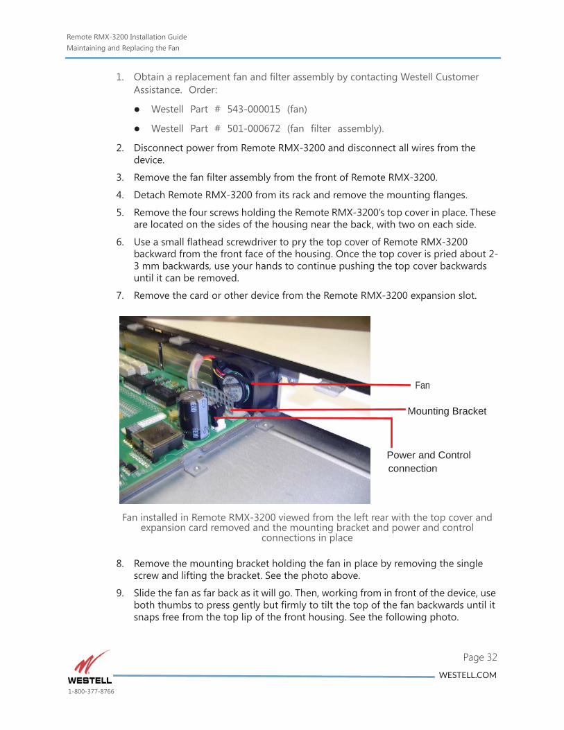
7. Remove the card or other device from the Remote RMX-3200 expansion slot.
Fan installed in Remote RMX-3200 viewed from the left rear with the top cover and expansion card removed and the mounting bracket and power and control
connections in place
8. Remove the mounting bracket holding the fan in place by removing the single screw and lifting the bracket. See the photo above.
9. Slide the fan as far back as it will go. Then, working from in front of the device, use both thumbs to press gently but firmly to tilt the top of the fan backwards until it snaps free from the top lip of the front housing. See the following photo.
Mounting Bracket
Fan
Power and Controlconnection
WESTELL.COM
1-800-377-8766
Remote RMX-3200 Installation GuideMaintaining and Replacing the Fan
the
Page 33
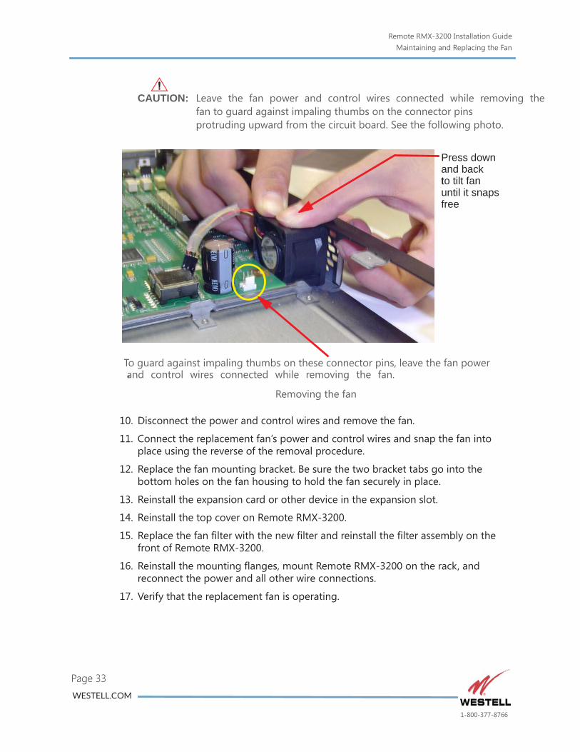
CAUTION: Leave the fan power and control wires connected while removingfan to guard against impaling thumbs on the connector pins protruding upward from the circuit board. See the following photo.
Removing the fan
10. Disconnect the power and control wires and remove the fan.
11. Connect the replacement fan’s power and control wires and snap the fan into place using the reverse of the removal procedure.
12. Replace the fan mounting bracket. Be sure the two bracket tabs go into the bottom holes on the fan housing to hold the fan securely in place.
13. Reinstall the expansion card or other device in the expansion slot.
14. Reinstall the top cover on Remote RMX-3200.
15. Replace the fan filter with the new filter and reinstall the filter assembly on the front of Remote RMX-3200.
16. Reinstall the mounting flanges, mount Remote RMX-3200 on the rack, and reconnect the power and all other wire connections.
17. Verify that the replacement fan is operating.
To guard against impaling thumbs on these connector pins, leave the fan power
Press downand backto tilt fanuntil it snapsfree
. and control wires connected while removing the fan.
t
WESTELL.COM
1-800-377-8766
Remote RMX-3200 Installation GuideTechnical Specifications
)
Page 34
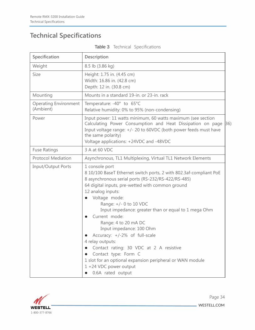
Technical SpecificationsTable 3 Technical Specifications
Specification Description
Weight 8.5 lb (3.86 kg)
Size Height: 1.75 in. (4.45 cm)Width: 16.86 in. (42.8 cm)Depth: 12 in. (30.8 cm)
Mounting Mounts in a standard 19-in. or 23-in. rack
Operating Environment(Ambient)
Temperature: -40° to 65°CRelative humidity: 0% to 95% (non-condensing)
Power Input power: 11 watts minimum, 60 watts maximum (see section Calculating Power Consumption and Heat Dissipation on page 36Input voltage range: +/- 20 to 60VDC (both power feeds must have the same polarity)Voltage applications: +24VDC and -48VDC
Fuse Ratings 3 A at 60 VDC
Protocol Mediation Asynchronous, TL1 Multiplexing, Virtual TL1 Network Elements
Input/Output Ports 1 console port8 10/100 BaseT Ethernet switch ports, 2 with 802.3af-compliant PoE8 asynchronous serial ports (RS-232/RS-422/RS-485)64 digital inputs, pre-wetted with common ground12 analog inputs: Voltage mode:
Range: +/- 0 to 10 VDCInput impedance: greater than or equal to 1 mega Ohm
Current mode:Range: 4 to 20 mA DCInput impedance: 100 Ohm
Accuracy: +/-2% of full-scale4 relay outputs: Contact rating: 30 VDC at 2 A resistive Contact type: Form C1 slot for an optional expansion peripheral or WAN module1 +24 VDC power output 0.6A rated output
WESTELL.COM
1-800-377-8766
Remote RMX-3200 Installation GuideCalculating Power Consumption and Heat Dissipation
Enter y be
wer rsion
ption oE
Page 35
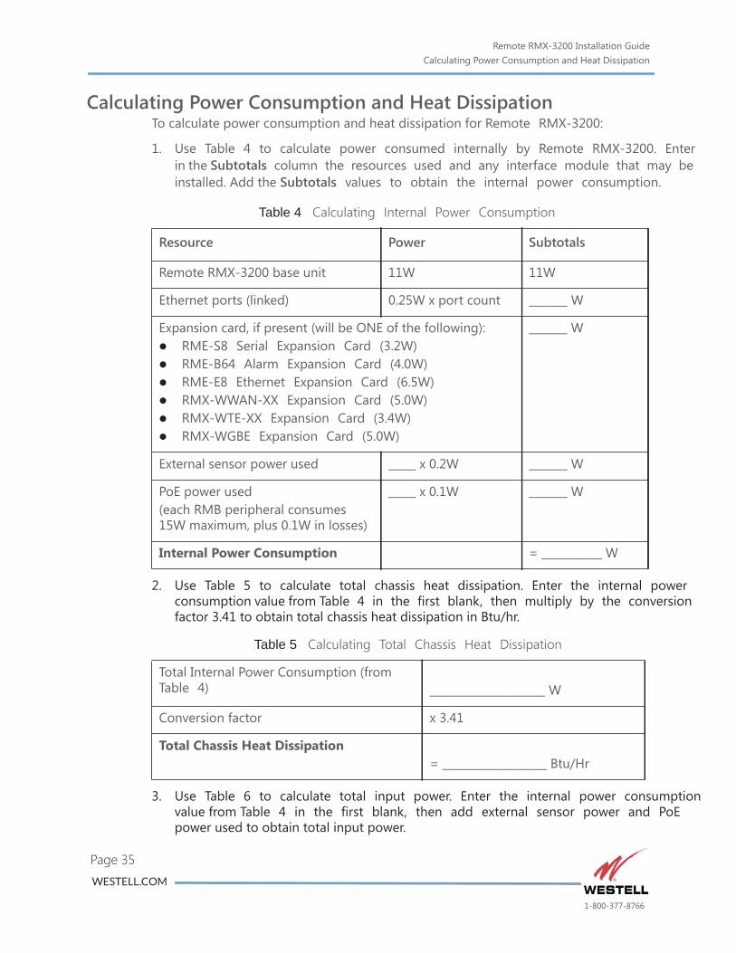
Calculating Power Consumption and Heat DissipationTo calculate power consumption and heat dissipation for Remote RMX-3200:
1. Use Table 4 to calculate power consumed internally by Remote RMX-3200. in the Subtotals column the resources used and any interface module that mainstalled. Add the Subtotals values to obtain the internal power consumption.
2. Use Table 5 to calculate total chassis heat dissipation. Enter the internal poconsumption value from Table 4 in the first blank, then multiply by the convefactor 3.41 to obtain total chassis heat dissipation in Btu/hr.
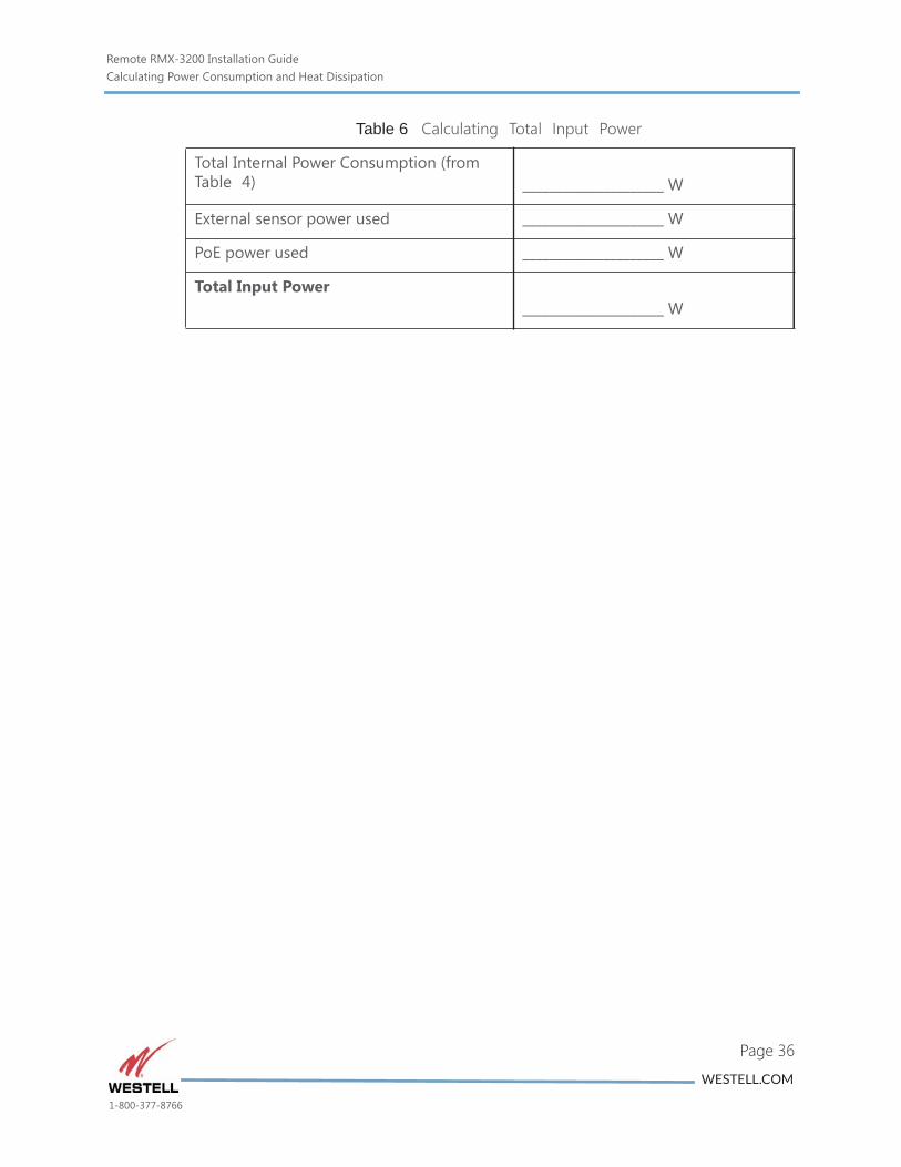
3. Use Table 6 to calculate total input power. Enter the internal power consumvalue from Table 4 in the first blank, then add external sensor power and Ppower used to obtain total input power.
Table 4 Calculating Internal Power Consumption
Resource Power Subtotals
Remote RMX-3200 base unit 11W 11W
Ethernet ports (linked) 0.25W x port count _______ W
Expansion card, if present (will be ONE of the following): RME-S8 Serial Expansion Card (3.2W) RME-B64 Alarm Expansion Card (4.0W) RME-E8 Ethernet Expansion Card (6.5W) RMX-WWAN-XX Expansion Card (5.0W) RMX-WTE-XX Expansion Card (3.4W) RMX-WGBE Expansion Card (5.0W)
_______ W
External sensor power used _____ x 0.2W _______ W
PoE power used(each RMB peripheral consumes 15W maximum, plus 0.1W in losses)
_____ x 0.1W _______ W
Internal Power Consumption = ___________ W
Table 5 Calculating Total Chassis Heat Dissipation
Total Internal Power Consumption (from Table 4) _____________________ W
Conversion factor x 3.41
Total Chassis Heat Dissipation= ___________________ Btu/Hr
WESTELL.COM
1-800-377-8766
Remote RMX-3200 Installation GuideCalculating Power Consumption and Heat Dissipation
Page 36
Table 6 Calculating Total Input Power
Total Internal Power Consumption (from Table 4) _____________________ W
External sensor power used _____________________ W
PoE power used _____________________ W
Total Input Power_____________________ W
WESTELL.COM
1-800-377-8766


