OUTLINE The FCX–AIII differential pressure transmitter accurately measures differential pressure, liquid level or gauge pres- sure and transmits a proportional 4 to 20mA signal. The transmitter utilizes a unique micromachined capacitance sili- con sensor with state-of-the-art microprocessor technology to provide exceptional performance and functionality. Totally welded construction of the seals assures excellent reliability in high temperature and highly corrosive process conditions. FEATURES 1. High accuracy 0.2% accuracy for all calibrated spans is a standard fea- ture for all DP models covering 0.32kPa {3.2mbar} range to 500kPa {5bar} high differential pressure range. 0.1% accuracy is available as option. 2. Minimum environmental influence The “Advanced Floating Cell” design which protects the pressure sensor against changes in temperature, static pressure, and overpressure substantially reduces total measurement error in actual field applications. 3. HART ® bilingual communications protocol FCX–AIII series transmitter offers bilingual communica- tions to speak both proprietary protocol and HART ® . Any HART ® compatible devices can communicate with FCX–AIII. 4. Application flexibility Various options that render the FCX–AIII suitable for al- most any process applications include: – Full range of hazardous area approvals – Built-in RFI filter and lightning arrester – 5-digit LCD meter with engineering unit – Stainless steel electronics housing – Wide selection of materials – High temperature, high vacuum seals 5. Programmable output Linearization Function In addition to Linear and Square Root, output signal can be freely programmable. (Up to 14 compensated points at approximation.) 6. Burnout current flexibility (Under Scale: 3.2 to 4.0mA, Over Scale: 20.0 to 22.5mA) Burnout signal level is adjustable using Model FXW Hand Held Communicator (HHC) to comply with NAMUR NE43. 7. Dry calibration without reference pressure Thanks to the best combination of unique construction of mechanical parts (Sensor unit) and high performance electronics circuit (Electronics unit), reliability of dry calibration without reference pressure is at equal level as wet calibration. SPECIFICATIONS Functional specifications Service: Liquid, gas, or vapor Static pressure, span, and range limit: } Up to flange rating F KD 3 FKD 5 FKD 6 +/- 32 {+/- 320} +/- 130 {+/- 1300} +/- 500 {+/- 5000} 0.32 { 3.2 } 1.3 { 13 } 5 { 50 } 32 { 320 } 130 { 1300 } 500 { 5000} Min. Type Range limit [kPa] {m bar} Span limit [kPa] (m bar} Max. Static pressure Remark : To minimize environmental influence, span should be greater than 1/40 of the max. span in most applications. Note: Refer to code symbols for the detail of span limit. – Lower limit of static pressure (vacuum limit), Silicone fill sensor: See Fig. 1 Fluorinated fill sensor: Atmospheric pressure – The maximum span of each sensor can be converted to different units using factors as below. 1MPa =10 3 kPa=10bar=10.19716kgf/cm 2 =145.0377psi 1kPa=10mbar=101.976mmH2O=4.01463H2O Overrange limit: To maximum static pressure limit Output signal: 4 to 20mA DC (linear or square root) with digital signal superimposed on the 4 to 20mA signal Power supply: Transmitter operates on 10.5V to 45V DC at transmitter terminals. 10.5V to 32V DC for the units with optional arrester. TG-L1002-0E Sep 2019 1st edition K FKD…5 REMOTE SEAL TYPE DIFFERENTIAL PRESSURE TRANSMITTER
Transcript
OUTLINE
The FCX–AIII differential pressure transmitter accurately measures differential pressure, liquid level or gauge pres-sure and transmits a proportional 4 to 20mA signal. The transmitter utilizes a unique micromachined capacitance sili-con sensor with state-of-the-art microprocessor technology to provide exceptional performance and functionality. Totally welded construction of the seals assures excellent reliability in high temperature and highly corrosive process conditions.
FEATURES
1. High accuracy0.2% accuracy for all calibrated spans is a standard fea-ture for all DP models covering 0.32kPa {3.2mbar} range to 500kPa {5bar} high differential pressure range. 0.1% accuracy is available as option.
2. Minimum environmental infl uenceThe “Advanced Floating Cell” design which protects the pressure sensor against changes in temperature, static pressure, and overpressure substantially reduces total measurement error in actual fi eld applications.
3. HART® bilingual communications protocolFCX–AIII series transmitter offers bilingual communica-tions to speak both proprietary protocol and HART®. Any HART® compatible devices can communicate with FCX–AIII.
4. Application fl exibilityVarious options that render the FCX–AIII suitable for al-most any process applications include:
– Full range of hazardous area approvals – Built-in RFI fi lter and lightning arrester – 5-digit LCD meter with engineering unit – Stainless steel electronics housing – Wide selection of materials – High temperature, high vacuum seals5. Programmable output Linearization Function
In addition to Linear and Square Root, output signal can be freely programmable.(Up to 14 compensated points at approximation.)
6. Burnout current fl exibility (Under Scale: 3.2 to 4.0mA, Over Scale: 20.0 to 22.5mA) Burnout signal level is adjustable using Model FXW Hand Held Communicator (HHC) to comply with NAMUR NE43.
7. Dry calibration without reference pressureThanks to the best combination of unique construction of mechanical parts (Sensor unit) and high performance electronics circuit (Electronics unit), reliability of dry calibration without reference pressure is at equal level as wet calibration.
SPECIFICATIONS
Functional specifications
Service: Liquid, gas, or vaporStatic pressure, span, and range limit:
} Up to fl ange rating
FKD 3
FKD 5
FKD 6
+/− 32{+/− 320}
+/− 130{+/− 1300}
+/− 500{+/− 5000}
0.32 { 3.2 } 1.3 { 13 } 5 { 50 }
32 { 320 } 130 { 1300 } 500 { 5000}
Min.Type
Range limit[kPa] {m bar}
Span limit [kPa](m bar}
Max.Static pressure
Remark : To minimize environmental infl uence, span should be greater than 1/40 of the max. span in most applications.
Note: Refer to code symbols for the detail of span limit.
– Lower limit of static pressure (vacuum limit), Silicone fi ll sensor: See Fig. 1 Fluorinated fi ll sensor: Atmospheric pressure – The maximum span of each sensor can be converted
to different units using factors as below. 1MPa =103kPa=10bar=10.19716kgf/cm2
=145.0377psi 1kPa=10mbar=101.976mmH2O=4.01463H2OOverrange limit: To maximum static pressure limitOutput signal: 4 to 20mA DC (linear or square root) with
digital signal superimposed on the 4 to 20mA signal
Power supply: Transmitter operates on 10.5V to 45V DC at transmitter terminals.
10.5V to 32V DC for the units with optional arrester.
TG-L1002-0ESep 20191st edition K
FKD…5
REMOTE SEAL TYPE
DIFFERENTIAL PRESSURE
TRANSMITTER
FKD…5 REMOTE SEAL TYPE DIFFERENTIAL PRESSURE TRANSMITTER
TG-L1002-0E2 TOKYO KEISO CO., LTD.
Process:
Fill fl uid Diaphragm seal7th code
Processtemperature
Lower limitof
static press.
Fluorinated oil W, A and D −20 to 120°CAtmosphericpressureSilicone oil U −15 to 250°C
X 20 to 350°C
Y and G −40 to 180°C 2.7kPa abs {20mmHg abs}S −15 to 250°C
K −15 to 200°C0.13kPa abs {1mmHg abs} or more
Storage: −40 to +90°CHumidity limit: 0 to 100% RHCommunication: With HHC(1) (Model FXW), following items
can be remotely displayed or confi gured. Note: HHC’s version must be higher than 7.0
(or FXW 1− 4), for FCX–AIII.Local confi gurator with LCD display (option): Local confi gurator with 3 push button and
LCD display can support following items.Items By communication
with FXWBy local confi gurator (with 3 push button)
Display Set Display Set
Tag No. v v v v
Model No. v v v v
Serial No. & Software Version v — v —
Engineering unit v v v v
Range limit v — v —
Measuring range v v v v
Damping v v v v
Output modeLinear v v v v
Square root v v v v
Burnout direction v v v v
Calibration v v v v
Output adjust — v — v
Data v — v —
Self diagnoses v — v —
Printer (In case of FXW with printer option) v — — —
External switch lock v v v v
Transmitter display v v v v
Linearize v v — —
Rerange v v v v
Saturate current v v v v
Write protect v v v v
History– Calibration history– Ambient temperature history
vv
v—
vv
v—
Programmable output linearization function:Output signal can be characterized with “14 points linear approximation function” from HHC(1).
(Note) (1) HHC: Hand Held Communicator
Load limitations: see fi gure below
2000
[Ω]
1500
1000
Load
res
ista
nce
500
250
0
1474Ω
577ΩOperatingarea
24V 45V
10 16.35 50 E[ V ]10.5V
Power voltage (DC)
R= E-10.5(Imax+0.9)x10-3
Note: For communication with HHC(1) (Model: FXW), min. of 250Ω is required.
Hazardous locations: TABLE 2Zero/span adjustment:
Zero and span are adjustable from the HHC(1). Zero and span are also adjustable externally from the adjustment screw.
Damping: Adjustable from HHC or local confi gurator unit with LCD display.
The time constant is adjustable between 0.06 to 32 seconds.
Zero elevation/suppression:−100% to +100% of URL
Normal/reverse action:Selectable from HHC(1)
Indication: Analog indicator or 5-digit LCD meter, as specifi ed.
Burnout direction: Selectable from HHC(1)
If self-diagnostic detect transmitter fail-ure, the analog signal will be driven to ei-ther “Output Hold”, “Output Overscale” or “Output Underscale” modes.
“Output Hold”: Output signal is hold as the value just before failure happens.
“Output Overscale”: Adjustable within the range 20.0mA to 22.5mA from HHC(1)
“Output Underscale”: Adjustable within the range 3.2mA to 4.0mA from HHC(1)
3.2 4 20 22.5 [mA]
Over scale Burnout
Probable over rangeProbable under range
Normal operating rangeUnder scale Burnout
Output limits conforming to NAMUR NE43 by order.Loop-check output:
Transmitter can be confi gured to provide constant signal 3.2mA through 22.5mA by HHC(1).
Temperature limit: Ambient: −40 to + 85°C (−20 to + 80°C for LCD indicator) (−40 to + 60°C for arrester option) (−10 to + 60°C for fl uorinated oil fi ll transmitter) (−10 to + 85°C for silicone oil “U”, “S”, “K”) *)
(+ 20 to + 85°C for silicone oil “X”) *)
*) In case of capillary length is more than 7m, max temperature is +55°C.
For explosionproof units (fl ameproof or intrinsic safety), ambient temperature must be within the limits speci-fi ed in each standard.
REMOTE SEAL TYPE DIFFERENTIAL PRESSURE TRANSMITTER FKD…5
TG-L1002-0E TOKYO KEISO CO., LTD. 3
500V AC, 50/60Hz 1 min., between cir-cuit and earth.
Insulation resistance:More than 100MΩ at 500V DC.
Internal resistance for external fi eld indicator:12Ω or less
Physical specifications
Electrical connections:G1/2, 1/2-14 NPT, Pg13.5, or M20 × 1.5 conduit, as specifi ed.
Process connections:JIS, ANSI, or DIN raised face fl anges.JIS: 10K80A, 10K100A, 30K80A, or
30K100AANSI: 150LB 3", 150LB 4", 300LB 3", or
300LB 4"DIN: PN40 DN80 or PN16 DN100See OUTLINE DIAGRAM for detailed dimensions.
Diaphragm extension:0, 50, 100, 150, or 200mm as specifi ed.(See model code. Extended diaphragm is available only with 316L stainless steel diaphragm)
Process-wetted parts material: Diaphragm: 316L stainless steel, MA276,
IEC IP67 and NEMA 6/6PMounting: On 60.5mm (JIS 50A) pipe using mount-
ing bracket, direct wall mountingMass {weight}: Transmitter approximately 12 to 31kg
without options. Add; 0.5kg for mounting bracket 4.5kg for stainless steel housing option 1.5kg per 50mm extension of dia-phragm
Optional features
Indicator: A plug-in analog indicator (2.5% accuracy).An optional 5-digit LCD meter with engi-neering unit is also available.
Local confi gurator with LCD display: An optional 5 digits LCD meter with 3
push buttons can support items as using communication with FXW.
Arrester: A built-in arrester protects the electronics from lightning surges. Lightning surge immunity:4kV (1.2 × 50µs)
Oxygen service: Special cleaning procedures are followed throughout the process to maintain all process wetted parts oil-free.The fi ll fl uid is fl uorinated oil.
Chlorine service: Oil-free procedures as above. Includes fl uorinated oil for fi ll.
Degreasing: Process-wetted parts are cleaned, but the fi ll fl uid is standard silicone oil. Not for use on oxygen or chlorine measurement.
Vacuum service: Special silicone oil and fi lling procedure are applied.See Fig. 1, Fig. 2.
Optional tag plate:An extra stainless steel tag for customer tag data is wired to the transmitter.
Performance specifications
Reference conditions, silicone oil fi ll, 316SS isolating diaphragms, 4 to 20mA analog output in linear mode.Accuracy rating: (including linearity, hysteresis, and re-
peatability) (Standard) For spans greater than 1/10 of URL: 0.2% of span For spans below 1/10 of URL:
(Option) (Code; 15th digit H, K, T, G) For spans greater than 1/10 of URL: 0.1% of span For spans below 1/10 of URL:
Stability: ±0.2% of upper range limit (URL) for 10 years.
Temperature effect (*):Effects per 28°C change between the limits of −40°C and +85°C
(Standard) Zero shift: ±0.35% of URL Total effect: ±0.5% of URL (Option) (Code; 15th digit J, K, F, G)
Zero shift: ±0.3% of URLTotal effect: ±0.4% of URL
Note: * Excluding effect by temperature difference between the seals.
Static pressure effect:Zero shift; 0.2% of URL / 1MPaSpan shift: −0.2% of calibrated span /
1MPaOverrange effect: Zero shift; 0.1% of URL for fl ange rating
FKD…5 REMOTE SEAL TYPE DIFFERENTIAL PRESSURE TRANSMITTER
TG-L1002-0E4 TOKYO KEISO CO., LTD.
ACCESSORIES
Hand-held communicator: Model FXW
ORDERING INFORMATION
When ordering this instrument, specify:1. CODE SYMBOLS2. Measuring range3. Output orientation (burnout direction) when abnormality
is occurred in the transmitter. Hold / Overscale / Underscale Unless otherwise specifi ed, output hold function is sup-
plied.4. Output mode (linear or square root output) Unless otherwise specifi ed, output mode is linear.5. Indication method (indicated value and unit) in case of
the actual scale (code D, H, P, S ,2 ,5 on 9th digit).6. Tag No. (up to 14 alphanumerical characters), if required.
–40 –15 8560 180 230 250
Silicone (Code Y,G)
Silicone (Code S)
Operating area101
{1010}53.3
{533}
13.3 {133}
2.7 {27}
[kPa abs]{mbar abs}
Ope
ratin
g p
ress
ure
Process temperature [°C]
Vacu
um a
rea
Non-operatingarea
Note: When using the transmitter in a vacuum area, locate it lower than the flange.
Sealing liquid:Silicone (Code K)
Operating area
Non-operatingarea
101{1010}
0.27 {2.7}0.13 {1.3}
[kPa abs]{mbar abs}
Ope
ratin
g p
ress
ure
200–15 100
Process temperature [°C ]
Vacu
um a
rea
Note: When using the transmitter in a vacuum area, locate it lower than the flange.
Fig. 2 Relation between process temperature and operating pressure
Fig. 1 Relation between process temperature and operating pressure
–15 25020 350
Silicone (Code X)
Operating area
Non-operating area
101{1010}
[kPa abs]{mbar abs}
Ope
ratin
g p
ress
ure
Process temperature [°C ]
Vacu
um a
rea
Silicone (Code U)
Fig. 3 Relation between process temperature and operating pressure
REMOTE SEAL TYPE DIFFERENTIAL PRESSURE TRANSMITTER FKD…5
TG-L1002-0E TOKYO KEISO CO., LTD. 5
How to specify a model
1. Select codes for the base model and the diaphragm seal separately. 2. Base model code: FKD 5- - …15 digits3. Diaphragm seal code: J …7 digits, for JIS fl ange A/S …7 digits, for ANSI/JPI · DIN fl ange4. Join the two, adding a slash (/) between them.
Example: FKDT43V5-1XC1Y-0* / SR4VYAY / SAR4VYAY
<Base model>
Digit1st, 2nd, 3rd Base model FKD Remote seal type differential pressure transmitter4th Amplifi er case T L shape case, conduit connection NPT1/25th Flange rating 4 Pressure standard 150LB6th Measurement span 3 Range 32 kPa7th Diaphragm material (fi xed to V) ····· To be specifi ed in diaphragm seal code8th Revision code 5 |9th Indicator 1 Local confi gurator with LCD display10th Approval for hazardous locations X ATEX fl ameproof11th Remote seal type C Capillary on HP & LP side12th Accessories 1 No stainless steel tag, no stainless housing13th Transmitter cell body fi lling oil (Fixed to Y) ····· Silicone oil |14th (Fixed) 015th (Fixed) *
<Hight pressure side>
1st Diaphragm seal type S Diaphragm seal for ANSI/JPI standards2nd Capillary connection R Side capillary3rd Flange size and rating 4 ANSI/JPI 150LB 3B4th Flange material V 316L SS5th Extension Y 0mm6th Capillary length A 1.5m7th Fill fl uid Y Silicone oil
<Low pressure side>
1st Diaphragm seal type S Diaphragm seal for ANSI/JPI standards2nd Capillary connection R Side capillary3rd Flange size and rating 4 ANSI/JPI 150LB 3B4th Flange material V 316L SS5th Extension Y 0mm6th Capillary length A 1.5m7th Fill fl uid Y Silicone oil
Base model HP side Diaphragm
seal
LP side Diaphragm
seal
FKD…5 REMOTE SEAL TYPE DIFFERENTIAL PRESSURE TRANSMITTER
TG-L1002-0E6 TOKYO KEISO CO., LTD.
CODE SYMBOLS
DescriptionDigit4 <AMP case>
<Conduit connection> <Case shape> G1/2 T shape 1/2-14NPT T shape Pg 13.5 T shape M20 × 1.5 T shape G1/2 L shape 1/2-14NPT L shape Pg 13.5 L shape M20 × 1.5 L shape
5 <Flange size and rating> ANSI/JPI 150 LB ANSI/JPI 300 LB ANSI/JPI 600 LB JIS 10K JIS 20K JIS 30K JIS 63K Screw type (316SS)
7 −
6 <Span limit (*1) [kPa]>
9
80A/3B or larger0.32… 321.3… 1305 …… 500
50A/2B or smaller3.2… 3213… 13050… 500
11 <Mounting design> Capillary on HP & LP side Rigid short design on HP & capillary on LP
<Indicator> <Scale> <Arrester> None − None Analog 0 to 100% linear scale None Analog 0 to 100% square root (*2) None Analog Custom scale None Analog Double scale (0 to 100% None linear/0 to 100% sq. root) None − Yes Analog 0 to 100% linear scale Yes Analog 0 to 100% square root (*2) Yes Analog Custom scale Yes Analog Double scale (0 to 100% Yes linear/0 to 100% sq. root) Digital 0 to 100% linear scale None Digital Custom scale None Digital 0 to 100% square root scale None Digital 0 to 100% linear scale Yes Digital Custom scale Yes Digital 0 to 100% square root scale Yes Digital (Local configurator unit with LCD) 0 to 100% linear scale None Digital (Local configurator unit with LCD) Custom scale None Digital (Local configurator unit with LCD) 0 to 100% square root scale None Digital (Local configurator unit with LCD) 0 to 100% linear scale Yes Digital (Local configurator unit with LCD) Custom scale Yes Digital (Local configurator unit with LCD) 0 to 100% square root scale Yes
10 <Approvals for hazardous locations> None (for ordinary location) TIIS Flameproof (Cable grand seal) (*3) TIIS Intrinsic safety FM Flameproof (or explosionproof) (*4) FM Intrinsic safety FM Combined of flameproof and intrinsic safety (*4) ATEX Flameproof ATEX Intrinsic safety ATEX Type n ATEX Combined of flameproof and intrinsic safety (*5) IECEx scheme, Flameproof (*5) IECEx scheme, Intrinsic safety CSA Flameproof (or explosionproof) (*4) CSA Intrinsic safety and nonincentive
Note3
Note4
Note4Note5
Note5Note5
Note4
Note1
Note2
Note2
Note
356
46L0137S
V
5678STVW
CE
ABCDJ
EFGHK
LPMQSN123456
ACGDHVXKPMRTEJ
4 5 6 71 2 3 8 9 10 11 12 13 14 15 Digit No.of codeF K D 5V
REMOTE SEAL TYPE DIFFERENTIAL PRESSURE TRANSMITTER FKD…5
TG-L1002-0E TOKYO KEISO CO., LTD. 7
*
Note 1: (*1) 100: 1 turn down is possible, but should be used at a span greater than 1/40 of the maximum span for better performance.Note 2: (*2) During the square root output mode, square root scale is not available.Note 3: (*3) Available for 4th digit code "S".Note 4: (*4) Available for 4th digit code "6", "T".Note 5: (*5) Available for 4th digit code "6", "8", "T", "W".Note 6: (*6) Customer tag number can be engraved on standard stainless steel name plate. If extra tag plate is required, select "Yes".Note 7: (*7) Not available for 10th digit code "C".Note 8: (*8) In case of hazardous location type, tagplate is made by Fuji Electric Co., Ltd.
14 - 0
15 <Fixed code> (*8)
13 -
Description12 <Option>
<Extra SS tag plate> <SS housing> None None Yes None None Yes Yes Yes
1234
Y
4 5 6 71 2 3
F K D 5 0Y8 9 10 11 12 13 14 15
NoteDigit No.of codeDigit
Note7
Note8
Note6
Note7(*6)(*7)
FKD…5 REMOTE SEAL TYPE DIFFERENTIAL PRESSURE TRANSMITTER
TG-L1002-0E8 TOKYO KEISO CO., LTD.
CODE SYMBOLS <Diaphragm seal for JIS>
1 2 3 4 5 6 7
J
Note 1 (*1) Select the appropriate digit codes for 1st to 3rd digit codes, so that they correspond to the fl ange specifi ed in the base model 5th digit code.For example, if base model 5th digit code is "0" (i.e. JIS10K), select JIS10K fl ange in 1st, 2nd, and 3rd digit codes for diaphragm seal.
Note 2: (*2) Available for 4rd digit code "V".
Note 3: (*3) Available for 3rd digit code "4", "5", "6".
Note 4: (*4) When 7th digit code is "S" or "K", 3rd digit code should be any of "7", "8", "9".
Note 5: (*5) Available for 7th digit code "Y", "W", "G", "A", "D".
Note 6: (*6) Available for all of 7th digit code.
Note 7: (*7) Select the specifi cation of LP side capillary with the digit codes for LP side diaphragm seal.
Note 8: (*8) Select the same fi ll fl uid for HP side and LP side.
Note 9: (*9) Available for 4th digit code "V".
Note 10: (*10) Available for 4th digit code "H", "T".
Note 11: (*11) Available for 4th digit code "V", "H".
Note 12: (*12) Available for 3rd digit code "4", "5", "6", "7", "8", "9", and for 4th digit code "V", "H".
Note 13: (*13) Available for 3rd digit code "4", "5", "6", "7", "8", "9", and for 4th digit code "V".
Digit Description Code Note
1 <Capillary connection> <Flange size and rating> Note 1
2 Flanged axial diaphragm
seal connection (Center
capillary)
JIS 10K 15A With fl ange adapter JAA Note 2
3 JIS 20K 15A With fl ange adapter JAB Note 2
JIS 30K 15A With fl ange adapter JAC Note 2
JIS 63K 15A With fl ange adapter JAE Note 2
JIS 10K 20A With fl ange adapter JAF Note 2
JIS 20K 20A With fl ange adapter JAG Note 2
JIS 30K 20A With fl ange adapter JAH Note 2
JIS 63K 20A With fl ange adapter JAL Note 2
JIS 10K 40A With fl ange adapter JAS Note 2
JIS 20K 40A With fl ange adapter JAT Note 2
JIS 30K 40A With fl ange adapter JAU Note 2
JIS 63K 40A With fl ange adapter JAW Note 2
JIS 10K 50A JAX
JIS 20K 50A JAY
JIS 30K 50A JA1
JIS 63K 50A JA3
JIS 10K 80A JA4
JIS 20K 80A JA5
JIS 30K 80A JA6
JIS 10K 100A JA7
JIS 20K 100A JA8
JIS 30K 100A JA9
<Capillary connection>
Flanged radial diaphragm
seal connection (Side
capillary)
JIS 10K 50A JRX
JIS 20K 50A JRY
JIS 30K 50A JR1
JIS 63K 50A JR3
JIS 10K 80A JR4
JIS 20K 80A JR5
JIS 30K 80A JR6
JIS 10K 100A JR7
JIS 20K 100A JR8
JIS 30K 100A JR9
<Capillary connection>
Wafer type
JIS 10K 50A JWX
JIS 20K 50A JWY
JIS 30K 50A JW1
JIS 63K 50A JW3
JIS 10K 80A JW4
JIS 20K 80A JW5
JIS 30K 80A JW6
JIS 10K 100A JW7
JIS 20K 100A JW8
JIS 30K 100A JW9
Digit Description Code Note
4 <Diaphragm seal material>
<Diaphragm> <Flange face> <Flange>
316L SS 316L SS 316L SS V
Hastelloy-C Hastelloy-C 316L SS H
Monel Monel 316L SS B
Tantalum Tantalum 316L SS T
Titanium Titanium 316L SS P Note 3
Zirconium Zirconium 316L SS R Note 3
316L SS + Au coating 316L SS 316L SS J
5 <Diaphragm extension>
None Y
50mm 4th digit code "V" only A Note 4
100mm 4th digit code "V" only B Note 4
150mm 4th digit code "V" only C Note 4
200mm 4th digit code "V" only D Note 4
6 <Remote seal type>
<Mounting design>
<Capillary length>
<Capillary armor>
<Mounting bracket>
Capillary 1.5m PVC 304L SS A Note 5
Capillary 3m PVC 304L SS B Note 5
Capillary 6m PVC 304L SS C Note 5
Capillary 5m PVC 304L SS 1 Note 5
Capillary 7m PVC 304L SS 2 Note 5
Capillary 8m PVC 304L SS 3 Note 5
Capillary 10m PVC 304L SS 4 Note 5
Capillary 1.5m SS 304L SS G Note 6
Capillary 3m SS 304L SS H Note 6
Capillary 6m SS 304L SS K Note 6
Capillary 5m SS 304L SS 5 Note 6
Capillary 7m SS 304L SS 6 Note 6
Capillary 8m SS 304L SS 7 Note 6
Capillary 10m SS 304L SS 8 Note 6
Rigid short design on HP & capillary on LP *Available for base model 11th digit code "E". *For LP side, only the center capillary is available.
R Note 7
7 <Treatment> <Fill fl uid> Note 8
None (Standard) Silicone oil Y
None (Standard) Fluorinated oil W
Degreasing Silicone oil G
Oxygen service Fluorinated oil A Note 9
Chlorine service Fluorinated oil D Note 10
High temp. (-15 to 250°C) Silicone oil U Note 11
High temp. (20 to 350°C) Silicone oil X Note 12
High temp and vacuum (-15 to 250°C) Silicone oil S Note 13
High temp and high vacuum (-15 to 200°C) Silicone oil K Note 13
REMOTE SEAL TYPE DIFFERENTIAL PRESSURE TRANSMITTER FKD…5
TG-L1002-0E TOKYO KEISO CO., LTD. 9
CODE SYMBOLS <Diaphragm seal for ANSI/JPI>
1 2 3 4 5 6 7
A/S
Digit Description Note
1 <Capillary connection> <Flange size and rating> Note 1
2 Flanged axial diaphragm
seal connection (Center
capillary)
ANSI/JPI 150LB 1/2B With fl ange adapter AAK Note 2
ANSI/JPI 600LB 1/2B With fl ange adapter AAM Note 2
ANSI/JPI 150LB 3/4B With fl ange adapter AAN Note 2
ANSI/JPI 300LB 3/4B With fl ange adapter AAP Note 2
ANSI/JPI 600LB 3/4B With fl ange adapter AAQ Note 2
ANSI/JPI 150LB 1.5B With fl ange adapter SAE Note 2
ANSI/JPI 300LB 1.5B With fl ange adapter SAF Note 2
ANSI/JPI 600LB 1.5B With fl ange adapter AAU Note 2
ANSI/JPI 150LB 2B SAH
ANSI/JPI 300LB 2B SAJ
ANSI/JPI 600LB 2B AAV
ANSI/JPI 150LB 3B SA4
ANSI/JPI 300LB 3B SA6
ANSI/JPI 600LB 3B AAW
ANSI/JPI 150LB 4B SA5
ANSI/JPI 300LB 4B SA7
ANSI/JPI 600LB 4B AAX
Screwed 1/2 NPT With fl ange adapter AA0
Screwed 3/4 NPT With fl ange adapter AA1
Screwed Rc1/2 With fl ange adapter AA2
Screwed Rc3/4 With fl ange adapter AA3
<Capillary connection> ANSI/JPI 150LB 2B SRH
Flanged radial
diaphragm seal
connection (Side
capillary)
ANSI/JPI 300LB 2B SRJ
ANSI/JPI 600LB 2B ARV
ANSI/JPI 150LB 3B SR4
ANSI/JPI 300LB 3B SR6
ANSI/JPI 600LB 3B ARW
ANSI/JPI 150LB 4B SR5
ANSI/JPI 300LB 4B SR7
ANSI/JPI 600LB 4B ARX
<Capillary connection> ANSI/JPI 150LB 2B SWH
Wafer type ANSI/JPI 300LB 2B SWJ
ANSI/JPI 600LB 2B AWV
ANSI/JPI 150LB 3B SW4
ANSI/JPI 300LB 3B SW6
ANSI/JPI 600LB 3B AWW
ANSI/JPI 150LB 4B SW5
ANSI/JPI 300LB 4B SW7
ANSI/JPI 600LB 4B AWX
Digit Description Code Note
4 <Diaphragm seal material>
<Diaphragm> <Flange face> <Flange>
316L SS 316L SS 316L SS V
Hastelloy-C Hastelloy-C 316L SS H
Monel Monel 316L SS B
Tantalum Tantalum 316L SS T
Titanium Titanium 316L SS P Note 3
Zirconium Zirconium 316L SS R Note 3
316L SS + Au coating 316L SS 316L SS J
5 <Diaphragm extension>
None Y
50mm 4th digit code "V" only A Note 4
100mm 4th digit code "V" only B Note 4
150mm 4th digit code "V" only C Note 4
200mm 4th digit code "V" only D Note 4
6 <Remote seal type>
<Mounting design>
<Capillary length>
<Capillary armor>
<Mounting bracket>
Capillary 1.5m PVC 304L SS A Note 5
Capillary 3m PVC 304L SS B Note 5
Capillary 6m PVC 304L SS C Note 5
Capillary 5m PVC 304L SS 1 Note 5
Capillary 7m PVC 304L SS 2 Note 5
Capillary 8m PVC 304L SS 3 Note 5
Capillary 10m PVC 304L SS 4 Note 5
Capillary 1.5m SS 304L SS G Note 6
Capillary 3m SS 304L SS H Note 6
Capillary 6m SS 304L SS K Note 6
Capillary 5m SS 304L SS 5 Note 6
Capillary 7m SS 304L SS 6 Note 6
Capillary 8m SS 304L SS 7 Note 6
Capillary 10m SS 304L SS 8 Note 6
Rigid short design on HP & capillary on LP *Available for base model 11th digit code "E". *For LP side, only the center capillary is available.
R Note 7
7 <Treatment> <Fill fl uid> Note 8
None (Standard) Silicone oil Y
None (Standard) Fluorinated oil W
Degreasing Silicone oil G
Oxygen service Fluorinated oil A Note 9
Chlorine service Fluorinated oil D Note 10
High temp. (-15 to 250°C) Silicone oil U Note 11
High temp. (20 to 350°C) Silicone oil X Note 12
High temp and vacuum (-15 to 250°C) Silicone oil S Note 13
High temp and high vacuum (-15 to 200°C) Silicone oil K Note 13
Note 1: (*1) Select the appropriate digit codes for 1st to 3rd digit codes, so that they correspond to the fl ange specifi ed in the base model 5th digit code.For example, if base model 5th digit code is "0" (i.e. JIS10K), select JIS10K fl ange in 1st, 2nd, and 3rd digit codes for diaphragm seal.
Note 2: (*2) Available for 4rd digit code "V".
Note 3: (*3) Available for 3rd digit code "4", "6", "W".
Note 4: (*4) When 7th digit code is "S" or "K", 3rd digit code should be any of "5", "7", "X".
Note 5: (*5) Available for 7th digit code "Y", "W", "G", "A", "D".
Note 6: (*6) Available for all of 7th digit code.
Note 7: (*7) Select the specifi cation of LP side capillary with the digit codes for LP side diaphragm seal.
Note 8: (*8) Select the same fi ll fl uid for HP side and LP side.
Note 9: (*9) Available for 4th digit code "V".
Note 10: (*10) Available for 4th digit code "H", "T".
Note 11: (*11) Available for 4th digit code "V", "H".
Note 12: (*12) Available for 3rd digit code "4", "5", "6", "7", "W", "X", and for 4th digit code "V", "H".
Note 13: (*13) Available for 3rd digit code "4", "5", "6", "7", "W", "X", and for 4th digit code "V".
FKD…5 REMOTE SEAL TYPE DIFFERENTIAL PRESSURE TRANSMITTER
TG-L1002-0E10 TOKYO KEISO CO., LTD.
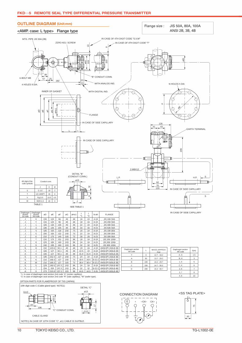
INNER OF GASKET
SEE TABLE 1
IN CASE OF 4TH DIGIT CODE "T"
IN CASE OF 4TH DIGIT CODE "S,V,W"
ZERO ADJ. SCREW
"B" CONDUIT CONN.
EARTH TERMINAL
P
øH±1
øF
L t
øEøD øG
N HOLES h DIA
øE
L.P. H.P.
IN CASE OF SIDE CAPILLARY
IN CASE OF SIDE CAPILLARY
IN CASE OF SIDE CAPILLARY
2-M8X12
S
S
57 25
10ø8
110
3
182
810
3 ø81
ø15
J
KM
12641 43
209
6270120
38
4 HOLES 9 DIA.
U-BOLT M8
FLANGE
(11)(21)
WITH ANALOG IND.
WITH DIGITAL IND.
4th digit of the code symbols
Conduit conn.
J K M
G 1/2 18 2
1/2-14NPT 16 4
Pg13.5 10.5 4.5
M20×1.5 16 4
S
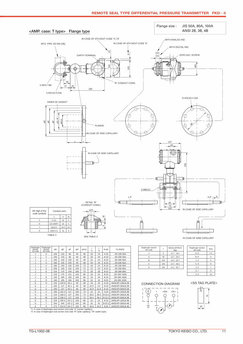
Y 0 12.7 - 18.2
A 50 13.7 - 29.2
B 100 14.2 - 29.7
C 150 14.7 - 30.2
D 200 15.2 - 30.7
T
V
W
MASS.APPROX(kg)
TABLE 1
A, G 1.5
B, H 3
1, 5 5
C, K 6
2, 6 7
3, 7 8
4, 8 10
S(m)LDiaphragm section5th code
Diaphragm section 6th code
MTG. PIPE JIS 50A (2B)
+ CK+
IN CASE OF SIDE CAPILLARY
G1/2
OPTION PARTS FOR FLAMEPROOF OF TIIS (JAPAN)
10th digit code C (Cable gland type) NOTE1)
CABLE GLAND
ø33.
5
10619
"C" CONDUIT CONN.
NOTE1) IN CASE OF 10TH CODE “C”, ø11 CABLE IS SUITBLE.
*1: In case of diaphragm seal section 2nd code “A” (center capillary).*2: In case of diaphragm seal section 2nd code “R” (side capillary), “W” (wafer type).
OUTLINE DIAGRAM (Unit:mm)
<AMP. case: L type> Flange type
Flange size : JIS 50A, 80A, 100A ANSI 2B, 3B, 4B
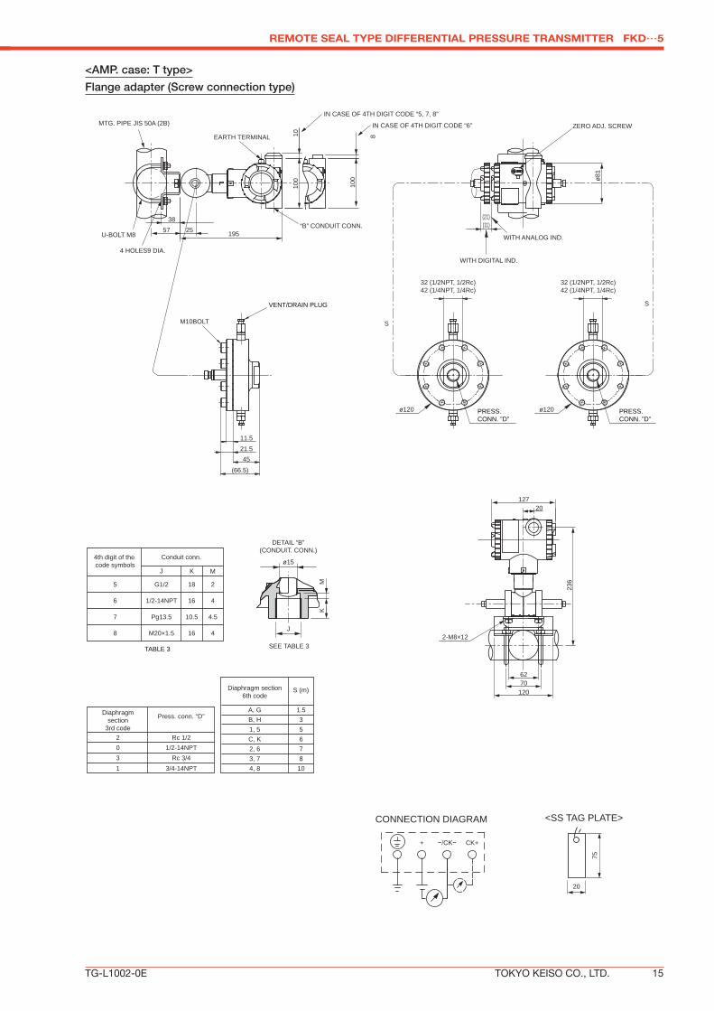
<AMP. case: T type> Flange type
REMOTE SEAL TYPE DIFFERENTIAL PRESSURE TRANSMITTER FKD…5
*1: In case of diaphragm seal section 2nd code “A” (center capillary).*2: In case of diaphragm seal section 2nd code “R” (side capillary), “W” (wafer type).
Flange size : JIS 50A, 80A, 100A ANSI 2B, 3B, 4B
<AMP. case: L type>
Flange adapter (Flange connection type)
FKD…5 REMOTE SEAL TYPE DIFFERENTIAL PRESSURE TRANSMITTER
TG-L1002-0E12 TOKYO KEISO CO., LTD.
Conduit conn.
G1/2 18S
J K M
2
4th digit of the code symbols
1/2-14NPT 16T 4
Pg13.5 10.5V 4.5
M20×1.5 16W 4
(11)(21)
WITH ANALOG IND.
WITH DIGITAL IND.
N HOLES h DIA
+ CK+
209
EARTH TERMINAL
41 43
103
8
57
38
25182
ZERO ADJ. SCREWIN CASE OF 4TH DIGIT CODE "T"
IN CASE OF 4TH DIGIT CODE "S,V,W"
ø81
ø81
103
10
MTG. PIPE JIS 50A (2B)
U-BOLT M8
4 HOLES 9 DIA.
6270120
2-M8×12TABLE 2
126
"B" CONDUIT CONN.
S SK
M
SEE TABLE 2
J
ø15
NOTE1) IN CASE OF 10TH CODE “C”, ø11 CABLE IS SUITBLE.
*1: In case of diaphragm seal section 2nd code “A” (center capillary).*2: In case of diaphragm seal section 2nd code “R” (side capillary), “W” (wafer type).
TABLE 1
4th digit of the code symbols
Conduit conn.
J K M
G 1/2 18 2
1/2-14NPT 16 4
Pg13.5 10.5 4.5
M20×1.5 16 4
5
6
7
8
SEE TABLE1
J
DETAIL “B”(CONDUIT. CONN.)
KM
+ CK+
75
20
<SS TAG PLATE>CONNECTION DIAGRAMG1/2
OPTION PARTS FOR FLAMEPROOF OF TIIS (JAPAN)
10th digit code C (Cable gland type) NOTE1)
CABLE GLAND
ø33.
5
10619
"C" CONDUIT CONN.
NOTE1) IN CASE OF 10TH CODE “C”, ø11 CABLE IS SUITBLE.
FKD…5 REMOTE SEAL TYPE DIFFERENTIAL PRESSURE TRANSMITTER
TG-L1002-0E18 TOKYO KEISO CO., LTD.
ATEX Ex II 2 GD Ex d IIC T6 IP66/67 T85°C Tamb = −40°C to +65°C Ex d IIC T5 IP66/67 T100°C Tamb = −40°C to +85°C
Factory Mutual
Class I Div.1 Groups B, C, D T6 Type 4XClass II III Div.1 Groups E, F, G T6 Type 4X Tamb max = +60°C
CSA Class I Div.1 Groups C, DClass II Div.1 Groups E, F, GClass III Div.1
Note) “Seal Not Required” enclosure is allowed.
TIIS Ex do IIB+H2 T4 Tamb max = +60°C Maximum process temp. = +120°C
IECEx Scheme
Ex d IIC T5 IP66/67 Tamb = −40°C to +85°CEx d IIC T6 IP66/67 Tamb = −40°C to +65°C
Authorities Flameproof
ATEX Ex II 1 G Ex ia IIC T5 Tamb = –40°C to +50°C Ex ia IIC T4 Tamb = –40°C to +70°C Entity Parameters: Ui=28V, Ii=94.3mA, Pi=0.66W, Ci=26nF (Without Arrester), Li=0.6mH (Without analog indicator), Ci=36nF (With Arrester), Li=0.7mH (With analog indicator)
Factory Mutual
Class I II III Div.1 Groups A, B, C, D, E, F, G T4 Entity Type 4X
CSA Class I Div.1 Groups A, B, C, D Class II Div.1 Groups E, F, G Class III Div.1 Temp Code T5 Tamb max = +50°C Temp Code T4 Tamb max = +70°C Entity Parameters: Vmax=28V, Imax=94.3mA, Ci=25nF (Without Arrester), Ci=36nF (With Arrester), Li=0.6mH (Without analog meter), Li=0.7mH (With analog meter)
TIIS Ex ia IIC T4 Tamb max = +60°CEntity Parameters: Ui=28V, Ii=94.3mA, Pi=0.66W, Ci=40.92nF, Li=0.694mH
IECEx Scheme
Ex ia IIC T4 Tamb = –40°C to +70°C Ex ia IIC T5 Tamb = –40°C to +50°C Entity Parameters: Ui=28V, Ii=94.3mA, Pi=0.66W, Ci=26nF (Without Arrester), Li=0.6mH (Without analog indicator), Ci=36nF (With Arrester), Li=0.7mH (With analog indicator)
Authorities Intrinsic safety
Base model Diaphragm9th digit 7th digit A,B,C,D Y,G,U,X,S,K −40°C to +85°CL,M,P,1,2,3 Y,G,U,X,S,K −20°C to +80°CN,Q,S,4,5,6 Y,G,U,X,S,K −20°C to +60°CE,F,G,H Y,G,U,X,S,K −40°C to +60°C − W,A,D −10°C to +60°C
Temp
ATEX Ex II 3 GD EEx nL IIC T5 Tamb = −40°C to +50°C EEx nL IIC T4 Tamb = −40°C to +70°CSpecific Parameters:Model without arrester: Ui=42.4V, Ii=113mA, Pi=1W, Ci=25.18nF, Li=0.694mHModel with arrester: Ui=32V, Ii=113mA, Pi=1W, Ci=35.98nF, Li=0.694mH
EEx nAL IIC T5 Tamb = −40°C to +50°C EEx nAL IIC T4 Tamb = −40°C to +70°CSpecific Parameters:Model without arrester: Umax=42.4V, Imax=113mA, Pmax=1WModel with arrester: Umax=32V, Imax=113mA, Pmax=1W
Factory Mutual(pending)
Class I II III Div.2 Groups A, B, C, D, F, G T4 Entity Type 4X
AuthoritiesType n
Nonincendive
Base model Diaphragm9th digit 7th digit A,B,C,D Y,G,U,X,S,K −40°C to +85°CL,M,P,1,2,3 Y,G,U,X,S,K −20°C to +80°CN,Q,S,4,5,6 Y,G,U,X,S,K −20°C to +60°CE,F,G,H Y,G,U,X,S,K −40°C to +60°C − W,A,D −10°C to +60°C
Temp
TABLE 2
REMOTE SEAL TYPE DIFFERENTIAL PRESSURE TRANSMITTER FKD…5
TG-L1002-0E TOKYO KEISO CO., LTD. 19
FKD…5 REMOTE SEAL TYPE DIFFERENTIAL PRESSURE TRANSMITTER
TG-L1002-0E20 TOKYO KEISO CO., LTD.
Head Office : Shiba Toho Building, 1 – 7 – 24 Shibakoen, Minato-ku, Tokyo 105 – 8558