Page 1
1
Removal of 1,4-Dioxane from
Water by Adsorption to Resins
Major Qualifying Project completed in partial fulfillment
Of the Bachelor of Science Degree at
Worcester Polytechnic Institute, Worcester, MA
Submitted by:
Christopher Martineau
Harsha Prasad
Patrick Roll
Professor John Bergendahl, faculty advisor
Professor Isa Bar-On, faculty co-advisor
May 1, 2014
Page 2
2
Abstract
The purpose of this project was to evaluate resins as adsorbents for removing 1,4-dioxane
from water. The objective of this study was to find new type of remediation technology for 1,4-
dioxane. A range of resins with various properties and characteristics were tested to determine if
adsorption is a viable option for removing this water-soluble contaminant.
Page 3
3
Contents Abstract ......................................................................................................................................................... 2
Table of Figures ............................................................................................................................................ 4
Table of Tables ............................................................................................................................................. 4
Executive Summary ...................................................................................................................................... 5
1.0 Introduction ............................................................................................................................................. 6
1.1 Chemical Contaminant ........................................................................................................................ 6
1.1.1 Direct Uses of 1,4-Dioxane .......................................................................................................... 8
1.2 EPA Classification .............................................................................................................................. 9
1.3 Exposure ............................................................................................................................................. 9
2.0 Effect on Environment .......................................................................................................................... 11
3.0 Occurrences/Case Studies ..................................................................................................................... 12
3.1 Japan ................................................................................................................................................. 12
3.2 Colorado ............................................................................................................................................ 13
3.3 Indiana............................................................................................................................................... 13
3.4 California (San Jose) ......................................................................................................................... 14
3.5 Michigan ........................................................................................................................................... 16
3.6 California (Orange County) .............................................................................................................. 19
4.0 Risk and Regulation .............................................................................................................................. 20
4.0.1 Federal ........................................................................................................................................ 21
4.0.2 Massachusetts ............................................................................................................................ 23
4.1 Policy Implications ........................................................................................................................... 24
5.0 Current Remediation Techniques.......................................................................................................... 26
5.1 Resin Types ....................................................................................................................................... 29
6.0 Methodology ......................................................................................................................................... 31
7.0 Results ................................................................................................................................................... 33
8.0 Discussion and Design .......................................................................................................................... 39
8.1 Reactor Systems ................................................................................................................................ 39
8.2 Reactor Design .................................................................................................................................. 40
8.3 Cost Analysis .................................................................................................................................... 44
9.0 Conclusions ........................................................................................................................................... 47
Appendix A Resin Data .............................................................................................................................. 48
Page 4
4
Appendix B: Images ................................................................................................................................... 52
Image 1: Gas Chromatography Machine ............................................................................................ 52
Image 2: 24 Hour Mixer...................................................................................................................... 53
Image 3: L-493 Resin .......................................................................................................................... 53
Image 4: XAD4 Resin ......................................................................................................................... 54
Bibliography/References ............................................................................................................................. 55
Acknowledgements ..................................................................................................................................... 59
Table of Figures
Figure 1: Molecular Structure of 1,4-Dioxane ............................................................................................ 10
Figure 2: 1,4-Dioxane Standard by State .................................................................................................... 23
Figure 3: Freundlich Isotherm for all L-493 Data ....................................................................................... 34
Figure 4: Langmuir Isotherm for all L-493 Data Points ............................................................................. 35
Figure 5: Langmuir Model for all L-493 Data Points ................................................................................. 36
Figure 6: Freundlich Isotherm for all XAD4 Data Points ........................................................................... 36
Figure 7: Langmuir Isotherm for all XAD4 Data Points ............................................................................ 37
Figure 8: Freundlich Model for all XAD4 Data Points............................................................................... 37
Figure 9: Fixed-Bed Reactor with Dual Columns System Schematic ........................................................ 40
Figure 10: Fixed-Bed Reactor Example ...................................................................................................... 41
Figure 11: Fixed-Bed Reactor Components ................................................................................................ 45
Table of Tables
Table 1: Structural Properties of the 1,4-Dioxane Molecule ........................................................................ 7
Table 2: Properties of 1,4-Dioxane ............................................................................................................... 8
Table 3: Producers of 1,4-Dioxane (circa 1985) ......................................................................................... 20
Table 4: 1,4-Dioxane Standards by State .................................................................................................... 22
Table 5: Resin Concentration's (Testing Examples) ................................................................................... 32
Table 6: Concentrations of Resins after Equilibrium .................................................................................. 38
Table 7: Resin Required for Reactor System .............................................................................................. 44
Table 8: Budget Level Costs ....................................................................................................................... 46
Table 9: Resin Cost ..................................................................................................................................... 46
Table 10: Multiple Trial Values .................................................................................................................. 48
Table 11: L-493 Data .................................................................................................................................. 49
Table 12: Langmuir Data ............................................................................................................................ 50
Table 13: XAD4 Data ................................................................................................................................. 51
Page 5
5
Executive Summary
1,4-dioxane is a widely-used solvent and can be found in oils, waxes, dyes, cellulose
acetate, as well as other organic and inorganic compounds. There are many occurrences of 1,4-
dioxane contamination in the environment; the most common case is seepage of 1,4-dioxane
from decomposed manufactured products in landfills to the soil and groundwater around it. The
products decompose and the contamination then moves into groundwater sources, which in turn
affects drinking water (EPA 123-91-1, Jan. 2000). When 1,4-dioxane contaminates the
groundwater it becomes a direct threat to human and ecological health. Short-term effects
resulting from human exposure to high concentrations of 1,4-dioxane include drowsiness,
headache, irritation to skin, and irritation to the lungs (EPA 123-91-1, Jan. 2000). 1,4-dioxane
exposure has also been proven to be fatal in some circumstances. Due to its widespread
occurrence in the environment, effective remediation techniques for removal of this contaminant
are needed. The purpose of this project was to evaluate adsorptive resins to determine their
potential for removal of 1,4-dioxane from water.
Four resins were evaluated in this project. The resins used included Dowex L-493,
Amberlite XAD4, Dowex Marathon C, and Amberlite XAD7HP. These resins were evaluated at
different doses. In the experiments, the resin dose was varied from trial to trial; however, the
amount of 1,4-dioxane in each batch adsorption test remained constant. For example, 0.5 g of a
resin would be mixed for 24 hours with 40 mL of water and 100 microliters of 1,4-dioxane. It
was then prepared for testing by adding 50 microliters of 10 mg/L of chlorobenzene and 4 g of
NaCl. The 1,4-dioxane concentration was quantified using gas chromatography with solid phase
microextraction (SPME-GC). Results ranged based on the concentration and specific resin type.
SPME-GC was utilized to conduct experiments with the aim of determining if the resins changed
Page 6
6
the concentration of 1,4-dioxane in the sample. Experiments were carried out with initial
concentrations of each resin mixed with water, NaCl, and a fixed amount of 1,4-dioxane.
Using gas chromatography testing, the early stages of our experimentation yielded resins
XAD4 and L-493 as the most effective for removal of 1,4-dioxane per mass of resin. Based on
background research, the two resins were a viable option for adsorption because both have
properties that enabled them to adsorb oil and gas compounds in solution. Since both of these
resins showed promise through early experimentation, they were further tested at various
concentrations to try to create an isotherm as well as reproducible data and methods for 1-4-
dioxane removal.
1.0 Introduction
The objective of the project was to identify and create a reproducible experiment or
procedure in which 1,4-dioxane can be removed from freshwater. Based on current research in
water and wastewater treatment, remediation for removal of this particular contaminant has been
found to be difficult. The process used in our groups experiments was adsorption. For adsorption
to occur, it is necessary that the sorbent (resin) has an affinity for the contaminants that are to be
removed; therefore, due to the differing properties of the different resins tested, each resin
produced a different result depending on the respective concentrations of solution and
contaminant.
1.1 Chemical Contaminant
1,4-dioxane is a colorless, flammable liquid with a slightly sweet odor and is classified
as an ether. 1,4-dioxane is used as a solvent for cellulose acetate, ethyl cellulose, benzyl
Page 7
7
cellulose, resins, oils, waxes, some dyes, and other organic as well as inorganic compounds
(Mohr, 2010). Its primary use in the United States is as a stabilizer for methyl chloroform
(Mohr, 2010). In the 1950s and 1960s there was a large demand for 1,4-dioxane for this purpose
and approximately 90% of the 1,4-dioxane produced annually in the mid-1980s was also used for
this purpose (Mohr, 2010).
Bond Bond Length (Å) Bond Angle Components Bond Angle (°) Structure
C-H 1.112
C-O 1.423 C-C-O 109.2 Chair
C-C 1.523 C-O-C 112.45
Table 1: Structural Properties of the 1,4-Dioxane Molecule
(Table 1 Source: Mohr, 2010)
Page 8
8
Property Value Notes
Molecular Weight 88.106 Da Da = Daltons
Density 1.028 g/cm3 grams per centimeters cubed
Composition C 54.53%; H 9.15%; O 36.32% Carbon, Hydrogen, Oxygen
Boiling Point 101.2°C C = Celsius
Heat of
Vaporization
98.6 cal/g calories per gram
Freezing Point 11.85°C
Heat of Fusion 33.8 cal/g
Specific Heat 36.01 cal/(mol*K) calories divided by moles multiplied by
Kelvin
Table 2: Properties of 1,4-Dioxane
(Table 2 Source: Mohr, 2010)
1.1.1 Direct Uses of 1,4-Dioxane
The leading U.S. producer of 1,4-dioxane, Ferro Corporation, lists the following uses of 1,4-
dioxane on its web site (Ferro Corporation, 2006):
Wetting and dispersing agent in textile processing
Dye baths and stain and printing compositions
Some cleaning and detergent preparations, adhesives, cosmetics, deodorants, fumigants,
emulsions, and polishing agents
Some lacquers, paints, varnishes, and paint and varnish removers
Solvent for fats, oils, waxes, and natural and synthetic resins
Purification of drugs
Page 9
9
Reaction media in various organic synthesis reactions
Stabilizer for chlorinated solvents
Through these uses, Ferro Corporation was expected to comply with the Environmental
Protection Agency policies.
1.2 EPA Classification
The EPA has classified 1,4-dioxane as a Class B2 (probable) human carcinogen (ESEPA,
2000). The EPA has also established a drinking water health advisory with a lifetime cancer risk
of 1 in 10,000 for a drinking water concentration of 0.3 mg/L. There are many occurrences of
1,4-dioxane in the environment. Due to its widespread use it is often found in wastewater
streams (USEPA, 2000). 1,4-dioxane is also found in a variety of consumer products where
manufacturing waste will often be treated; however, the 1,4-dioxane cannot be removed in
typical wastewater treatment plants. 1,4-dioxane’s chemical structure gives it an extremely high
aqueous solubility making it difficult to biodegrade. These properties are a factor in it its
potential hazard to surface water and groundwater. The chemical attributes also make it difficult
to remove 1,4-dioxane from water and wastewater (USEPA, 2000). The 1,4-dioxane, used in
commercial products, such as cosmetics, has been known to penetrate groundwater more than
one mile away from the landfill that it was dumped in 1,4-dioxane can be found in air, water, and
soil and can be in the form of a vapor and a liquid (USEPA, 2000).
1.3 Exposure
1,4-dioxane can enter a human being’s system very easily and by several different
methods. For people who work with 1,4-dioxane the exposure rate can be high and those
individuals must take proper safety precautions. In the presence of 1,4-dioxane vapor, a person
Page 10
10
can become ill from the inhalation of the vapor (USEPA, 2000). Consuming foods that have
been exposed to 1,4-dioxane is another way the contaminate can enter into one's system. Another
simple way of absorbing 1,4-dioxane is when an individual bathes in contaminated water causing
the 1,4-dioxane to come into contact with the skin (USEPA, 2000). The most common way 1,4-
dioxane contaminates humans is by ingesting the 1,4-dioxane. Since the 1,4-dioxane does not
readily bind to soil, it easily contaminates the groundwater. Therefore, the exposure rate is much
higher than many other contaminants (USEPA, 2010).
Figure 1: Molecular Structure of 1,4-Dioxane
(Figure 1 Source: Mohr, 2010) – [red = oxygen, gray = carbon, white = hydrogen]
When a person drinks water contaminated by 1,4-dioxane the consumption of
contaminated water puts the 1,4-dioxane directly into the human system and as a result typically
causes severe health issues. Health issues vary in type and severity depending on the level of
exposure (Mohr, 2010). As discussed in the Executive Summary acute (short-term) inhalation to
Page 11
11
high levels of 1,4-dioxane can result in vertigo, drowsiness, headache, anorexia, and irritation of
the eyes, nose, throat, and lungs (USEPA 2000). Chronic (long-term) exposure in drinking water
increases the risk of cancer has also been observed to cause damage to the liver and kidneys
(USEPA 2000).
2.0 Effect on Environment
When released into the environment 1,4-dioxane causes a negative effect on the
surrounding environment. The greater the quantity of 1,4-dioxane corresponds to a more serious
environmental impact. Aqueous contamination by 1,4-dioxane impacts the quality of the water,
which poses a threat to both human health and ecological health. National Pollution Discharge
Elimination System Regulations (NPDES) cover regulations for point-source discharge of
industrial wastewater, storm water; and other water streams that have contamination (Mohr,
2010). “The goal of the NPDES is to restrict or eliminate environmental impacts to aquatic life
in surface water from both direct discharges into streams or indirect discharges into publicly
owned treatment works (POTWs), including discharges with high biochemical oxygen demand,
toxic metals and organic compounds, high temperatures, foaming agents, and other potential
impacts” (Mohr, 2010). The impact on the environment from the release of 1,4-dioxane varies by
the location and conditions of release into the environment. Although 1,4-dioxane is not highly
toxic to aquatic organisms, it becomes a threat to aquatic organisms if the concentration reaches
levels of hundreds to tens of thousands of milligrams per liter (mg/L) (Mohr, 2010).
1,4-dioxane poses the same level of threat to wildlife as it does to humans. Wildlife can
be exposed to 1,4-dioxane in the same manner as humans can be exposed. Methods of exposure
include ingestion, inhalation, and contact with skin. Exposure to terrestrial wildlife via the food
Page 12
12
chain is not as significant when looking at the typical concentrations of 1,4-dioxane in soil
(Mohr, 2010). Chronic 1,4-dioxane exposure can cause serious harm to wildlife’s internal
organs; liver, heart, and kidney damage was observed in laboratory trials of rats ingesting 1,4-
dioxane contaminated water over a long period of time (USEPA 2000).
3.0 Occurrences/Case Studies
Due to the large number of items that contain petroleum based products, there are various
avenues in which 1,4-dioxane can enter the environment. 1,4-dioxane has been found in many
international sites as well common domestic sources in the United State. Some of the methods in
which 1,4-dioxane contaminates water are: through Superfund sites, point source or non-point
source pollution from old buildings or development, and private/public companies that require
manufacturing. Case studies have provided benchmarks for the success or failure and cost of
techniques selected to treat water contaminated with 1,4-dioxane. The experiences of the water
utilities and the drinking water regulators in places where 1,4-dioxane has contaminated the
drinking water has been helpful to other utilities that have unfortunately discovered 1,4-dioxane
in their drinking water supplies. The following are a few examples of 1,4-dioxane instances
throughout the United States and the world.
3.1 Japan
Due to the multitude of manufactured products that contain trace levels of 1,4-dioxane
the contaminate has been found in numerous international sites. As a result of a nationwide
survey in Japan in 1995–1996, the level of 1,4-dioxane was reported to range from undetectable
to 16 μg/L in nineteen surface water samples from ten sites taken out of six rivers. The range was
Page 13
13
from 0.3 to 0.9 μg/L for three coastal seawater samples taken from three different sites, and the
range of 1,4-dioxane from undetectable to 79 μg/L for twenty-five groundwater samples from
twenty five different sites (Abe, 1997). The concentration of 1,4-dioxane in raw water from the
water supply ranged from undetectable to 9.1 μg/L (Abe, 1997). There was a high correlation
between the concentrations of 1,4-dioxane and 1,1,1-trichloroethance (Abe, 1999). No serious
health problems have been reported as a result of the nationwide survey.
3.2 Colorado
Another example of 1,4-dioxane trace levels was a case in Murphy Creek, CO. The
presence of 1,4-dioxane was detected in Murphy Creek (near Denver, CO) at locations where
contaminated groundwater is thought to enter the creek. Concentrations measured in Murphy
Creek ranged from undetectable to as high as 79 ug/L within the Denver Arapahoe Disposal Site
(DADS) property, north of the Lowry Landfill. North of the DADS property, the concentrations
ranged from non-detectable up to 10 ug/L. The state of Colorado has established a 1,4-dioxane
standard of 6.1 µg/L for surface water. Again, no health problems were reported near Murphy
Creek that could be linked to 1,4-dioxane exposure.
3.3 Indiana
In Jackson County, Indiana from 1970 to early 1980, the Seymour Recycling Corporation
(SRC) processed, stored, and incinerated chemical wastes at its site. About one hundred homes
as well as land used for agriculture were contaminated as a result of the SRC activities and
practices. Hazardous and toxic wastes including solvents and metal finishing wastes accumulated
on the site property over several years. The waste was stored in 55-gallon drums, bulk tanks, and
Page 14
14
other containers. The waste products leaked and spilled from their containers creating both fire
and odor problems. The landfills received vapor degreasing still bottoms, solvent wastes, paint
filters, scintillation and other laboratory wastes (USEPA, 1987). Ink sludge, pesticide
containers, household products (with methyl chloroform as an ingredient), and industrial
sludge’s from textile production, resin production, and cellulose acetate membrane production
have shown a higher likelihood of 1,4-dioxane presence in leachate, gas, and affected
groundwater. The foremost risk at the SRC site included offsite migration of highly mobile
organic contaminants. The contaminants could travel to the nearest private well, one-quarter mile
northwest of the site. The concentrations were so high that exposure caused a risk higher than of
the levels equivalent to the 1 in 1,000,000 excess lifetime cancer risk. 1,4-dioxane was
specifically identified as having the potential to exceed the recommended risk levels at the
nearest private well in less than five years (USEPA,1987).
3.4 California (San Jose)
In Silicon Valley, Solvent Service Inc. (SSI) opened a facility in 1973 to reclaim spent
solvents and other wastes from printed circuit board manufacturers, wafer fabs (semiconductor
manufacturers), and other electronics in industrial manufacturing facilities. SSI treated solvents
using a treatment, storage, and disposal facility (TSDF) permit at a facility located on a three
acre parcel in an industrial area of San Jose, California. Leaking tanks in 1983 prompted testing
and the discovery of subsurface contamination was revealed. (Cal EPA, 2000). Solvents were
refined through the use of distillation and gravity phase separation. Distillation of vapor-
degreaser still bottoms further concentrated the stabilizer compounds, including 1,4-
Page 15
15
dioxane. Volatile organic compounds were first detected in shallow groundwater beneath
underground solvent-storage tanks, wash-down sumps, a drum-storage area, and an unloading
area for solvent tank trucks (Cameron-Cole, 2001). The volatile organic chemicals detected
included methyl ethyl ketone, acetone, xylene isomers, perchloroethylene, trichloroethylene,
methyl chloroform, 1,1-dichloroethane, cis-1,2-dichloroethylene, and others. The toxic
industrial chemicals at the SSI site included 1,4-dioxane, tetrahydrofuran (THF), and 1,3-
dioxolane, as well as a number of others. 1,4-dioxane and THF were detected frequently and at
elevated concentrations (up to 56,000 and 850 μg/L, respectively) (McCraven, 2006).
Prior to the discovery and characterization of 1,4-dioxane at the SSI site in 1998, it was
believed that the extent of groundwater contamination had been identified. Discovery of 1,4-
dioxane and THF led to an investigation to characterize their downgradient extent, which was
much greater than that of the chlorinated solvent. The additional characterization effort defined a
1,4-dioxane plume extending beyond the effective range of the existing remediation systems.
The findings were met with regulatory actions designed to expand the monitoring network by
installing additional monitoring wells and expanding the groundwater extraction system. The
operational schedule of the existing remedial systems was increased to 24 hours/day, 7
days/week (24/7) for on-site soil vapor extraction. An additional 87-foot-long off-site
groundwater extraction trench was installed to address 1,4-dioxane presence beyond the capture
zone of the existing system (Cameron-Cole, 2006). Although the presence of fine-grained
deposits limited the volatile organic compound migration, 1,4-dioxane and THF were estimated
to migrate up to 41 and 35 ft/year, respectively (Cameron-Cole, 2006).
Since the sources of 1,4-dioxane contamination were being cut off by extraction trenches,
the consultants have recently submitted findings indicating that concentrations should continue
Page 16
16
to decline, noting that perimeter wells are not expected to produce samples with detectable
concentrations of 1,4-dioxane. Declining concentrations of 1,4-dioxane in monitoring wells
between the off-site extraction trench and the perimeter monitoring wells support this
assertion. In 1998 a laboratory consultant decided it would be appropriate to reanalyze the full
complement of forty-eight (48) groundwater samples. 1,4-dioxane was detected in all of samples
except one monitoring well. Subsequent sampling revealed a maximum 1,4-dioxane
concentration of 340,000 μg/L (Cameron-Cole, 2006). As of 2006 there have been no lawsuits
filed by citizens affected by the 1,4-dioxane contamination, but there have been reports of an
above-average cancer rate in the affected area (Cameron-Cole, 2006).
3.5 Michigan
Gelman Sciences Inc., acquired by Pall Life Sciences in 1997 (P/GSI) and located in Ann
Arbor, Michigan, produced cellulose triacetate filters used in medical and other applications. 1,4-
Dioxane was used for producing microporous cellulose filters for scientific and medical
applications; P/GSI began using 1,4-dioxane to create a stronger solvent system in 1986 (Fotouhi
et al., 2006). In 1996, the company discontinued the use of 1,4-dioxane and phased out the line
of filters that required its use in production. The line was eventually replaced by an improved
filter product. At the time that P/GSI stopped using 1,4-dioxane, it was discovered that thirty (30)
private wells in the Scio Township area were contaminated with 1,4-dioxane. Approximately
850,000 pounds of 1,4-dioxane was used to form triacetate filters during the twenty years before
contamination was discovered (Fotouhi et al., 2006). The P/GSI site is the oldest and largest 1,4-
dioxane contamination case in the United States.
The Michigan Department of Natural Resources recommended discharge of wastewater
into infiltration lagoons and the removal of natural geologic barriers between the pond bottom
Page 17
17
and the water table 15 to 40 feet below the surface in order to facilitate slow infiltration into
groundwater (Kellogg, 2005). The state of Michigan issued P/GSI a permit in 1964 to install a
three-million-gallon wastewater lagoon to hold and infiltrate process wastes, which may have
contained 1,4-dioxane in concentrations as high as 25 mg/L (City of Ann Arbor, 2006; SRSW,
2006). In order to further increase its wastewater capacity P/GSI installed two additional
lagoons in 1966-67 as well as drilled an injection well at a cost of approximately $1,000,000 in
1981. Despite the multiple attempts to protect the surrounding environment from 1,4-dioxane,
in 1984 a University of Michigan graduate student discovered 1,4-dioxane in Third Sister Lake
near the P/GSI property in a section of Saginaw forest owned by the university. The following
year, 1,4-dioxane contamination was also discovered in nearby private wells during an
investigation conducted by the Washtenaw County Health Board. Between 1987 and 1994, after
learning of the discovery of 1,4-dioxane contamination in late 1985, P/GSI used a water supply
well to remove more than 25,000 pounds of 1,4-dioxane from groundwater near the plant. The
contaminated water was not treated; instead, it was discharged into the injection well under a
USEPA permit. The permitted practice of treating 1,4-dioxane laden wastewater in unlined
lagoons and spray irrigating wastewater on lawns and fields clearly contributed to the
widespread contamination of groundwater with 1,4-dioxane (Kellogg, 2005).
Beginning in 1986, investigations by the company identified soil contamination on the
P/GSI property and groundwater contamination extending off the property. Groundwater
concentrations of 1,4-dioxane were as high as 221,000 μg/L. The plumes collectively
encompassed an area of approximately 0.6 square miles, as defined by the Michigan drinking
water action level of 85 μg/L (Brode et al., 2005). Citizen groups define the plume to a 1 μg/L
contour and describe the plume of deeper 1,4-dioxane contamination as “18 million square feet
Page 18
18
and growing, three miles long and one mile wide” (Kellogg, 2005). 1,4-dioxane method
detection levels have ranged from 1 to 100 μg/L during the course of the project (Fotouhi et al.,
2006). Deeper contamination was discovered during an investigation in the Spring of 2001,
following the detection of 1,4-dioxane at 2 μg/L in the City of Ann Arbor’s Northwest Supply
well. The city turned off the well immediately following the detection, and investigations of deep
aquifer contamination began. After an intensive effort to characterize deep contamination,
concentrations as high as approximately 5000 μg/L were found deep in the Unit E aquifer.
P/GSI embarked on a series of treatability studies in the decades following the discovery
of 1,4-dioxane contamination in private wells. Early treatability studies focused on separation
methods using gas-phase separation, such as air stripping and steam stripping, and on solid-phase
separation using GAC. P/GSI’s treatability studies also tested destructive treatment methods
including chemical destruction using hydrogen peroxide, ozone, and chlorine; physical
destruction using UV light; and combinations of physical and chemical destruction methods.
Biological treatability studies included microbial methods such as activated sludge and bio
activated carbon, enzymes, and inoculation with engineered organisms (Fotouhi et al.,
2006). Site remediation began with contaminated soil removal; the most highly contaminated
soils were removed in 1979 and 1987 (MDEQ, 2000). After almost ten years with little to no
action in off-site remediation, full-scale groundwater treatment resumed in 1997. The selected
remedy for full-scale groundwater treatment was UV light + hydrogen peroxide (H2O2). P/GSI
operated a full-scale UV + H2O2 system at its facility to remediate groundwater containing high
concentrations of 1,4-dioxane. As of 2004, more than 60,000 pounds of 1,4-dioxane had been
extracted from the groundwater and destroyed by UV + H2O2 since treatment began in 1997.
(Brode et al., 2005) Altogether, P/GSI has pumped about four billion gallons of water and
Page 19
19
removed about 100,000 pounds of 1,4-dioxane. (Fotouhi et al., 2006) Since 1997, the company
has been spending $5.5 million/year to clean up 1,4-dioxane pollution. (Kellogg, 2005) The
value of the affected groundwater resources supplying residents of Ann Arbor, Scio Township,
and Ann Arbor Township has not been identified and there have been no civil lawsuits brought
about as of 2005 (Kellogg, 2005).
3.6 California (Orange County)
The Orange County Water District (OCWD) in Orange County, CA, was formed in 1933
to manage water supply and groundwater in a 360 square-mile area in the lower Santa Ana River
watershed, covering much of Orange County on the southern California coast. OCWD is the
water provider to about 2.3 million people in more than twenty cities, including Newport Beach,
Huntington Beach, and Seal Beach on the coast; Cypress and Fullerton on the northern end;
Anaheim and Yorba Linda to the east; and Santa Ana and Irvine to the south. The groundwater
basin is a 3000-ft-thick slab of alluvium on top of bedrock formations. The water supply wells
extend as deep as 1000 ft. Under normal operating conditions, groundwater is the resource for
about 70% of the water provided by OCWD. (Deshmukh, 2007) In December 2001, 1,4-
Dioxane was discovered in Water Factory 21 at concentrations ranging from 1 to 75 μg/L, as
well as two detections at 150 and 200 μg/L. Since the Talbert Gap injection barrier had been
receiving highly treated water from Water Factory 21 for decades, in January 2002 the OCWD
staff decided to sample nineteen water supply wells that drew water from the affected aquifers.
1,4-dioxane was detected in nine of these supply wells at concentrations ranging from 4 to 20
μg/L, which is above California’s 3 μg/L action level, but below the threshold for shutting down
said water supply wells (Mehta, 2002).
Page 20
20
Table 3 below shows all of the known major producers of 1,4-dioxane circa 1985. This
illustrates how 1,4-dioxane is manufactured and used globally.
Company Location
Ferro Corporation/Grant Chemical Division Baton Rouge, Louisiana, USA
Union Carbide South Charleston, West Virginia, USA
CPS Chemical Company Old Bridge, New Jersey, USA
Dow Chemical Company Freeport, Texas, USA
Ugine-Kuhlmann Frankfurt, Germany
BASF Aktiengesellschaft Ludwigshafen, Germany
Dow Chemical Company Terneuzen, Netherlands
Osaka Organic Chemical Industry, Ltd. Osaka, Japan
Sanraku-Ocean Company Tokyo, Japan
Toho Chemical Industry Company Tokyo, Japan
Table 3: Producers of 1,4-Dioxane (circa 1985)
(Table 3 Source: Mohr, 2010).
4.0 Risk and Regulation
As a result of the pollution problems that occur in the environment, the Clean Water Act,
also known as the Federal Water Pollution Control Act, developed standards to preserve the uses
of a specific body of water by devising a list of criteria to protect the habitat from degradation by
unknown hazards. The purpose of these guidelines was designed to preserve the flora, fauna,
and environment.
Page 21
21
4.0.1 Federal
There is currently no federal MC or MCL Goal for 1,4-dioxane in drinking water.
However according to the Environmental Protection Agency (EPA) website dating as far back as
2008 there are currently twenty-two (22) states that have standards for the allowable
concentration of 1,4-dioxane in micrograms per liter (µg/L). The state standards are illustrated
in Table 4 and Figure 2 below. Two states, Michigan and South Carolina, have a much higher
concentration standard when compared to the other states. The heightened standards are due to
the number of occurrences of 1,4-dioxane in those states being much greater than the rest of the
states. It is simply not feasible, nor is it safe for the citizens of those states, to have lower
standards for Michigan and South Carolina.
Page 22
22
State 1,4-Dioxane Standard
Arizona 6.1 µg/L
Arkansas 6.1 µg/L
California 3 µg/L
Colorado 6.1 µg/L
Delaware 6 µg/L
Florida 3.2 µg/L
Louisiana 6.1 µg/L
Maine 3.2 µg/L
Maryland 6.1 µg/L
Massachusetts 3 µg/L
Michigan 85 µg/L
Missouri 3 µg/L
Nevada 6.1 µg/L
New Hampshire 3 µg/L
New Mexico 6.1 µg/L
North Carolina 7 µg/L
Oklahoma 6.1 µg/L
Pennsylvania 5.6 µg/L
South Carolina 70 µg/L
Texas 8.3 µg/L
Virgina 6.1 µg/L
West Virginia 6.1 µg/L
Table 4: 1,4-Dioxane Standards by State
(Table 4 Source: Rayle, Spatial Synthesis, Oct. 2008)
Page 23
23
Figure 2: 1,4-Dioxane Standard by State
(Figure 2 Source: Rayle, Spatial Synthesis, Oct. 2008)
4.0.2 Massachusetts
Given that Worcester Polytechnic Institute is located in the state of Massachusetts our
project group researched any guidelines and regulations relating to 1,4-dioxane in Massachusetts
state laws. The guidelines below provide a good example and are similar to regulations found in
the rest of the 21 states that have state laws relating to 1,4-dioxane.
Guidelines
Drinking water: 3 μg/L (Mohr, 2010).
Groundwater (guidance value—issued in 2007)
Page 24
24
o 3 μg/L Groundwater (shallow aquifer with vapor-intrusion potential) (Mohr,
2010)
o 6000 μg/L Groundwater (ecological risk) (Mohr, 2010)
o 50,000 μg/L Soil (direct contact and leaching) or 0.005 mg/kg (Mohr, 2010).
4.1 Policy Implications
An important aspect of clean drinking water is prevention. Prevention is the only means
to preserve the national environment for future generations. In order to apply this precautionary
principle individuals must “be open, informed, and democratic and must include parties
potentially affected by the environmental consequence at issue” (Global Development Research
Center [GDRC], 1998). The purpose of this section is to highlight some important policy
implications that can arise when trying to find the best methods for contamination remediation.
The following five precautionary principles are listed below as a means for being proactive in
monitoring waste in the environment.
1. Acknowledge and respond to ignorance, as well as uncertainty and risk, in technology.
2. Provide adequate long-term environmental and health monitoring and research into early
detection of environmental threats.
During the initial manufacturing of early solvent stabilizers certain consequences of
adding toxic and persistent compounds to chlorinated solvents prevailed. This toxic
aspect of the process was overlooked as the health issues to employees and eventual
smog occurred in the 1960’s. Although there were such drastic changes, there was little
motivation to promote water quality protection with solvents treated as hazardous waste.
This protection came only with the adoption of the Resource Conservation and Recovery
Page 25
25
Act (RCRA) in 1976. Creation of the RCRA helped individuals realize the potential risk,
particularly in relation to occupational exposure. Eventually there were discoveries
identifying the risk to workers, but not delving into the environmental effects. The
widespread use of these chemicals was not regulated thus making it difficult to address
the uncertainty of health effects and risks. The identification of risks to workers was tied
to the precautionary concept for occupational health and exposure. In early
manufacturing there was little information related to the direct health consequences of
exposure. In time the frequency of 1,4-dioxane use increased because it was employed as
a solvent stabilizer. (Barber, 1934) With the increase in production, eventually toxicology
research warranted both health monitoring and further research into the potentially toxic
effects of exposure.
3. Identify and work to reduce “blind spots” and gaps in scientific knowledge.
Since 1,4-dioxane is known to be used as a solvent stabilizer, there has been oversight
prior to its introduction into manufacturing. A key aspect of this rule, is the role of 1,4-
dioxane in the potential harm from chemicals during the time period. Certain processes,
such as vapor degreasing, yielded much higher quantities of 1,4-dioxane than the solvent
stabilizer itself. In addition, both industry and Government personnel overlooked the
possibility that direct dumping of hazardous wastes into sewers or the sending of
drummed solvent wastes to unlined landfills would cause significant groundwater
contamination.
4. Identify and reduce interdisciplinary obstacles to learning.
Page 26
26
For industrial chemists, in addition to professionals in the field, the impact of disposal
methods was not analyzed therefore the dangerous impacts were unable to be prevented.
A major factor behind the lack of preventive contamination planning was the
absence of motivation or the presence of a mandate requiring the assessment of health
risks from their own chemical inventions in the environment.
5. Avoid “paralysis by analysis” by acting to reduce potential harm when there are reasons.
The “paralysis by analysis” refers to the long timeframe required to investigate the
potential presence of a chemical in the environment before it is considered for regulation.
The phrase is used because residents have been consuming contaminated water for an
extended length of time. In scenarios where the information is available on the
environmental consequences of emerging contaminants, there has been an absence of
“political will” to take action to reduce hazards in the face of conflicting costs and
benefits. (EEA, 2000)
5.0 Current Remediation Techniques
1,4-dioxane is a contaminant that is difficult to extract from water due to its high
solubility. Soil contaminated with 1,4-dioxane is rare to find since 1,4-dioxane is known to
bypass soil and directly dissolve into groundwater. In a document on 1,4-dioxane, the EPA
describes the contaminant by claiming “1,4-dioxane’s physical property indicates that it is
theoretically volatile enough to be removed in situ using soil vapor extraction or ex situ with
thermal desorption even though its vapor pressure is lower than many volatile organic
compounds” (EPA-542-R-06-009).
Page 27
27
1,4-dioxane contamination is most commonly seen in groundwater. T reatments that have
proven successful in extracting 1,4-dioxane from groundwater involve advanced oxidation
involving hydrogen peroxide and UV light. Another form proven slightly less successful, but has
had some success, is chlorination. The concern with chlorination is the byproduct tends to be
more toxic than the 1,4-dioxane itself. This raises the question of whether it is worth using
chlorination. It is difficult to remove 1,4-dioxane from the environment because it is so highly
volatile.
One method of extracting the groundwater for testing is through water pump testing.
Water Pump Testing is conducted to determine if the groundwater is contaminated. Water Pump
Testing is also used to control contaminated water to prevent further pollution. The Water Pump
Testing process works by pumping out the groundwater. The groundwater undergoes ex-situ
treatment and is released. Water Pump Testing remediation is a good temporary fix for a small
local problem but for long term solutions this process will cost far too much for the temporary
reward it offers.
In a document on 1,4-dioxane, the EPA described the contaminant by stating “1,4-
Dioxane’s physical property indicates that it is theoretically volatile enough to be removed in situ
using soil vapor extraction or ex situ with thermal desorption even though its vapor pressure is
lower than many volatile organic compounds” (EPA-542-R-06-009, December 2006).
Since the most widespread presence of the contaminant 1,4-dioxane is in groundwater
more specific ways of extracting it have been attempted . Six remedial technologies have been
studied to remove 1,4-Dioxane from contaminated groundwater. The six processes (Mohr, 2010)
consist of:
1. Vapor-phase transfer (air stripping)
Page 28
28
2. Sorption
3. Natural attenuation
4. Phytoremediation
5. Bioremediation
6. Chemical oxidation.
Vapor-Phase Transfer (air Stripping) removes 1,4-dioxane from groundwater by
converting the 1,4-dioxane contaminant from its liquid phase into its vapor phase. Once the
contaminant is in the vapor phase it is filtered so when the vapor is released back into the
atmosphere it is non-toxic. “Air Stripping is a common method of removing volatile organic
compounds from groundwater because the relationship between solubility and volatility is
optimal in this group of contaminants” (Mohr, 2010). One of the most powerful air stripping
processes is the Accelerated Remediation Technologies, LLC (ART). ART is “a more focused
and comprehensive mass-transfer approach-combining air stripping, air sparing, soil-vapor
extraction, enhanced bioremediation, and underground circulation. It has been proven to be
effective for 1,4-dioxane removal under specific circumstances” (Mohr 2010). The figure below
is the ART method. This method has been proven to reduce 1,4-dioxane levels; however, the
process for removal is still undetermined.
Sorption is another remediation technique studied to remove 1,4-dioxane from
groundwater. Sorption was the area of concentration our group chose to research and our
experiments were focused around the process of sorption in extracting 1,4-dioxane from ground
water. Different materials can be used in the process of sorption depending on how the process is
performed. Activated carbon, clays, and synthetic resins are all materials that possess adsorptive
Page 29
29
qualities (Mohr, 2010). This specific project focused on sorption via resins to achieve clean
water. The specific resins are as follows.
5.1 Resin Types
In the current market there are numerous resins that are available each with their own
properties for adsorption. The resins with high hydrogen content are primarily used for solutes
and solvents with highly polar attractions in addition to the removal of by products during the
manufacturing process for different industries. The first step was to conduct an experiment using
one resin per experiment. The goal was to determine if any of these existing resins would remove
1,4-dioxane from water. The resins evaluated were Dowex Optipore L-493, Amberlite XAD4,
Dowex Marathon C, and Amberlite XAD7HP. Four independent experiments were conducted
using these resins.
According to The Dow Chemical Company, Dowex Optipore L-493 is a polymer
adsorbent with a high surface area of 1100 m2/g and a pore volume of 1.16 cc/g. Its primary
purpose is to extract aromatic molecules from water. It is used in removing BTEX from oil field
produced water, chlorinated solvents from water, and VOC from water. This product was
manufactured to have a high organic loading, good regeneration efficiency, and being physically
stable (Products L-493, 2014).
Amberlite XAD4 was another resin is described according to The Dow Chemical
Company: “Amberlite XAD4 is a polymeric adsorbent based on highly cross linked, macro
reticular polystyrene, aliphatic, or phenol-formaldehyde condensate polymers” (Products XAD4,
2014). This resin can be used to extract pollutants from ground water and vapor streams. It is
also used to remove chlorinated solvents, herbicides, and pesticides from aqueous streams
Page 30
30
(Products XAD4, 2014). “Dowex Marathon C resin is a high capacity, gel strong acidation
exchange resin of uniform bead size distribution.” It is designed to “give high throughput and
economical operation in both water and non-water applications.” The small size of the resin and
its respective core strength causes the resin to partake in rapid exchange kinetics reactions during
operation and regeneration (Products Marathon C, 2014). The uniform beads of Dowex
Marathon C resin make the resin more efficient than others. It reduces the waste and decreases
the cost (Products Marathon C, 2014).
“Amberlite XAD7HP is a polymeric adsorbent, supplied as white insoluble beads. It is a
non-ionic all phatic acrylic polymer which derives its adsorptive properties from its patented
macro reticular structure” (Products Amberlite, 2014). The structure allows the resin to be more
stable physically and thermally. This resin can be used to remove polar compounds from
aqueous solvents, removal of non-aromatic compounds from polar solvents, recovery of plant
extracts, recovery of antibiotics, and removal of organic pollutants from aqueous waste,
groundwater, and vapor streams. It is used in food processing, bioprocessing, and pharmaceutical
processin (Products Amberlite, 2014).
Natural Attenuation has specific regulations asserted by the EPA. The EPA states that the
natural attenuation processes “acts without human intervention to reduce the mass, toxicity,
volume, or concentrations of contaminants in soil or groundwater” (USEPA 2000). Natural
attenuation is not usually used as a remediation for 1,4-dioxane but if it were to be used it would
require significant adherence to the EPA’s evaluation elements.
Phytoremediation is the process of removing contaminants from groundwater or soil by
the use of plants. The largest phytoremediation process is transpiration. “Transpiration involves
Page 31
31
the transfer of soluble groundwater contaminants through the plant’s root, stem, and leaf systems
to the atmosphere” (USEPA 2000). The process for removing 1,4-dioxane from groundwater
through the use of phytoremediation has been proven successful in numerous experiments. The
primary removal mechanisms include uptake into the plant and transpiration of the 1,4-dioxane
out of the leaves and into the atmosphere. Since 1,4-dioxane dissipates quickly in the
atmosphere, the transpiration process could definitely be considered an effective long-term
method for the removal and destruction of 1,4-dioxane (USEPA 2000).
6.0 Methodology
The purpose of this study was to identify possible resins that could adsorb 1,4-dioxane
from water. Due to the nature of 1,4-dioxane, very few filtration techniques remove it from
solution. To test the solubility of the compound and dissolution properties, resins were used to
try and remove the contaminant from water.
For the first resin L-493 and the additional three resins a scale was used to measure the
respective quantities of resin which varied throughout the experiment. After the resins were
weighed out and transferred into their respective 40 mL VOA Vials, water and 1,4-dioxane
concentrate were added to solution. During the course of the experiment two variations were
used to mix the 1,4-dioxane with the resin. The first method involved pipetting 100 uL of a 2000
mg/L 1,4-dioxane concentrate, and the other method involved using a prepared batch of 5 mg/L
solution at pH 7 of 1,4-dioxane solution.
After the 1,4-dioxane solution was added to the resins in the vials, they were mixed for
twenty-four (24) hours. Throughout the tests from week to week there was always a “control”
Page 32
32
vial with 1,4-dioxane in solution that mixed with the other samples. After the twenty-four (24)
hours the samples were either stored in a refrigerator or run that same day.
To test each sample using the BTEX method on the gas chromatographer, 4 grams of
NaCl was added to each GC vial. The next step required transferring 10ml of each sample out of
each VOA vial into a respective GC test vial. This procedure was repeated for all of the samples
using a different pipette tip to prevent contamination.
Table 5 illustrates examples of the concentrations that were used in our planned
procedure for testing the 1,4-dioxane. The test matrix represents a subset of the actual
experiments conducted in the laboratory.
Type Of Resin Dowex Optipore L-493
Trial 1 2 3
Amount Resin (g) .5 g 1 g 1.5 g
Amount of Chemical (uL) 100uL 100uL 100uL
Concentration of Chemical (mg/L) 5 mg/L 5 mg/L 5 mg/L
Type Of Resin Amberlite XAD4
Trial 1 2 3
Amount Resin (g) .5 g 1 g 1.5 g
Amount of Chemical (uL) 100uL 100uL 100uL
Concentration of Chemical (mg/L) 5 mg/L 5 mg/L 5 mg/L
Table 5: Resin Concentration's (Testing Examples)
Page 33
33
7.0 Results
The following data represents the isotherms of the XAD4, L-493, and the non-ideal resins
XAD7HP and Dowex Marathon C. In the section below, the logarithmic Qe vs Ce tables,
Isotherms, and equations representing the ideal conditions for the resins can be seen with their
respective Ce removal.
The purpose of manipulating the data into a logarithmic scatter plot was to identify a
linear trend in the data. We used the Qe vs Ce table as a means to identify the concentration of
the 1,4-dioxane to the surface of the adsorbent to the concentration of the 1,4 in solution at
equilibrium for the Freundlich Isotherm. The resulting relationship dictates the proper Qe value
that can be the most efficient for contaminant removal.
Freundlich Equation:
The slope of the trend line is equivalent to the 1/n value and 10x, with ‘x’ referring to the
y-intercept as K. The values for the slope and y-intercept are taken from the logarithmic
calculations Qe vs Ce values.
The Langmuir Isotherm also requires the similar relationship but with regards of
adsorption of molecules to the relative gas pressure or concentration of a medium at a fixed
temperature.
Langmuir Equation:
Page 34
34
The Langmuir Isotherm required calculation for both constants. The empirical constant
and Saturation Coefficient for L-493 and XAD4 are 5.05, 1100 m3/g, and 3.15, 750 m3 /g
respectively. For all of the Qe vs Ce tables the concentration of Ce is in mg/L and the units for Qe
g/gal (grams per gallon).
Figure 3 below identifies the Freundlich Isotherm for the L-493 data points. This figure
identifies the linear trend in the data with a very poor regression value. Since this isotherm does
not identify a clear correlation of Qe vs Ce the Langmuir Isotherm can be used as an alternative.
Figure 3: Freundlich Isotherm for all L-493 Data
Figure 4 below shows the calculated Langmuir isotherm. The regression value for this
isotherm is significantly better making it the better isotherm to use for 1,4-dioxane removal
y = 0.1923x - 0.8673R² = 0.036
-1.40
-1.20
-1.00
-0.80
-0.60
-0.40
-0.20
0.00
-0.5 0 0.5 1
Qe
Ce
Freundlich Isotherm L-493
Freundlich Isotherm L-493
Linear (FreundlichIsotherm L-493 )
Page 35
35
calculations.
Figure 4: Langmuir Isotherm for all L-493 Data Points
It is evident that the L-493 resin has a lower accepted regression value than that of the
Langmuir Isotherm. As a result, the Langmuir Isotherm for L-493 was used for reactor
calculations in the next chapter of this report.
Figure 5 below depicts the Langmuir Model for L-493, the optimal resin, based on the
data acquired. The linear regression identifies this resin as a high efficiency for the given
parameters.
y = -0.0322x + 0.1703R² = 0.4389
0.00
0.05
0.10
0.15
0.20
0.25
0.00 2.00 4.00 6.00
Qe
Ce
Langmuir Isotherm L-493
Langmuir Isotherm L-493
Linear (Langmuir Isotherm L-493 )
Page 36
36
Figure 5: Langmuir Model for all L-493 Data Points
Figure 6 below depicts the Freundlich Isotherm for the resin we identified as the second
most effective (XAD4) in the logarithmic scale.
Figure 6: Freundlich Isotherm for all XAD4 Data Points
Figure 7 below is the Langmuir Isotherm for XAD4.
5.04
5.042
5.044
5.046
5.048
5.05
5.052
0.00 2.00 4.00 6.00
Qe
Ce
Langmuir Model
Langmuir Model
Log. (Langmuir Model )
y = -1.0144x - 0.3027R² = 0.2137
-2
-1.5
-1
-0.5
0
0 0.2 0.4 0.6 0.8
Qe
Ce
Freundlich Isotherm XAD4
Freundlich Isotherm XAD4
Linear (Freundlich IsothermXAD4 )
Page 37
37
Figure 7: Langmuir Isotherm for all XAD4 Data Points
These isotherms show that both resins are viable but with significantly different
regression. Although the Langmuir model was better for the L-493 resin, in this situation the
Freundlich model gives a better fit for XAD4. As a result a model for the Freundlich Isotherm of
XAD4 is below.
Figure 8: Freundlich Model for all XAD4 Data Points
Although the Freundlich Isotherm had the best fit line with respective regression, the
model itself does not yield a possible outcome. This model doesn’t show the ideal removal for a
removal system; therefore L-493 is the best option. Based on these results, if a treatment system
y = -0.0059x + 0.0416R² = 0.0348
-0.15
-0.1
-0.05
0
0.05
0.1
0.15
0.2
0.25
0.00 2.00 4.00 6.00 8.00
Qe
Ce
Langmuir Isotherm XAD4
Langmuir Isotherm XAD4
Linear (Langmuir IsothermXAD4)
0
0.1
0.2
0.3
0.4
0.5
0.00 2.00 4.00 6.00 8.00
Qe
Ce
Freundlich Model XAD4
Freundlich Model XAD4
Log. (Freundlich ModelXAD4)
Page 38
38
was to be able to treat contaminated water with a 1,4-dioxane concentration of 50 µg/L, 1 mg/L,
and 5 mg/L, the respective calculated Qe values from the given equation in the Langmuir
Isotherm for L-493 would be 0.17, 0.138, and 0.0093 respectively. These numbers are based on
the assumption that the goal of the system is 100% removal of contaminant.
Table 6 below shows the calculated concentration values for resin XAD7HP and
Marathon C. Considering the starting concentration for all trials was 5 mg/L, it was evident that
these trials proved inconclusive because some of the calculated values were well over 5 mg/L.
Since these values were over the normal and control, they were considered outliers and were not
used for the isotherm data or reactor system.
Peak Area
(Pa*s)
Dowex C Ce
(mg/L) Peak Area (Pa*s) XAD7HP Ce (mg/L)
395.56 1.695543 10402.21 44.58842
706.76 3.029482 10233.4 43.86482
1621.09 6.9487 14623.3 62.68185
1755.87 7.526426 9886.6 42.37829
2075.85 8.898 14819.2 63.52157
Table 6: Concentrations of Resins after Equilibrium
The control peak area for this trial was 1166.47 Pa*s. Some of the values recorded were
significantly larger than the standard. Considering these results were not ideal for this application
Page 39
39
it was expected to receive outlier data. Due to the variation from the resins in Table 6, these
resins were not tested further; we continued our project with the emphasis on L-493 and XAD4.
8.0 Discussion and Design
As stated earlier our group determined that L-493 was the most effective resin in
removing 1,4-dioxane from water. In most of the trials L-493 caused a significant decrease in the
concentration of 1,4-dioxane, even with very small amounts of the resin. The next step was to
choose a real world reaction system that could treat water contaminated with 1,4-dioxane
through the use of synthetic resin L-493. After research we decided that we should attempt to
design a system that can treat 10,000 gallons of contaminated water per day.
8.1 Reactor Systems
One type of reactor system that we researched for this project was a fixed-bed contactor
system. “A fixed-bed system consists of a stationary column in which the waste flows through
the bed at a constant rate” (Celenza, 2000). Fixed-bed systems are best used for the process of
adsorption using the Mass Transfer Zone (MTZ) height as a characteristic for adsorption
(Celenza, 2000). A multiple unit system is more practical for a fixed-bed system; it enables
flexibility in the reaction process and allows for mass production and efficiency. The main
purpose of the second column in the multiple unit system is to act as a safety net; this will protect
against negative discharge when the first column is exhausted (Celenza, 2000). In our case the
reactants and the catalysts include the contaminated water and resin. A single column can carry
out a sequence of different operations without the need to break containment which is useful
when dealing with toxic material such as 1,4-dioxane; however, the second column acting as a
safety will allow for secondary scrubbing to ensure all the 1,4-dioxane has been extracted and the
Page 40
40
water purified (Celenza, 2000). The goal of this part of the project was to use a fixed-bed system
to treat water that had been contaminated with 1,4-dioxane by the process of adsorption using
resins.
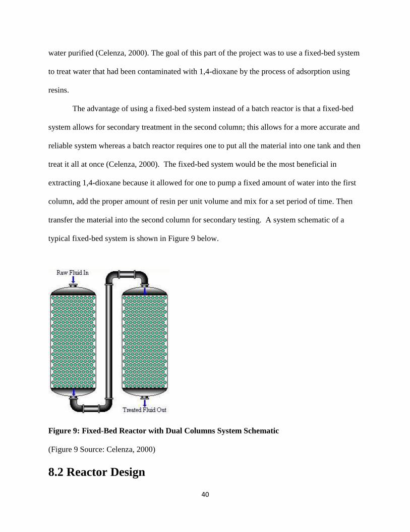
The advantage of using a fixed-bed system instead of a batch reactor is that a fixed-bed
system allows for secondary treatment in the second column; this allows for a more accurate and
reliable system whereas a batch reactor requires one to put all the material into one tank and then
treat it all at once (Celenza, 2000). The fixed-bed system would be the most beneficial in
extracting 1,4-dioxane because it allowed for one to pump a fixed amount of water into the first
column, add the proper amount of resin per unit volume and mix for a set period of time. Then
transfer the material into the second column for secondary testing. A system schematic of a
typical fixed-bed system is shown in Figure 9 below.
Figure 9: Fixed-Bed Reactor with Dual Columns System Schematic
(Figure 9 Source: Celenza, 2000)
8.2 Reactor Design
Page 41
41
The first step in our design of a dual fixed-bed reactor system was to determine
the size of the contactor. The contactor height, width, and bed depth is dependent on transfer
units related to the influent and effluent concentration (to determine contact time) as well as the
equilibrium characteristics of our L-493 and 1,4-dioxane contaminated water. The contactor
diameter is based on loading limitations and maintaining a physically stable contactor bed
(Celenza, 2000). Assuming a contact time of contaminated water and resin of one hour based on
our experimental results we can determine the contactor must be able to hold up to 416.67
gallons at a time (converted from 10,000 gallons per day to 416.7 gallons per hour). We
designed for a 500 gallon tank, which requires about 70 cubic feet to operate. We decided to size
our contactor with a height of 4 feet and a radius of 2.36 feet (diameter of 5.57 feet). An
example of a contactor of this size is shown below in Figure 10.
Figure 10: Fixed-Bed Reactor Example
(Figure 10 Source: Products. Alibaba.com®. Accessed 4/30/2014)
The chosen reactor design to be used will call for piping installation that will be able to
withstand the anticipated amount of flow into and out of the reactor filter. Our anticipated flow
rate of ten thousand gallons per day will call for a fairly small pipe size. The pipe material we
Page 42
42
chose for the chamber is Poly Vinal Chloride (PVC) piping. The way to determine what size
piping is needed one must calculate the flow rater per unit time. Using PVC piping in batch
reactor system requires that the piping consist of “domestically produced rigid PVC compound
Type 1 Grade 1, with a Cell classification of 12454 as defined in ASTM D1784 and approved by
the National Sanitation Foundation (NSF)” [Harvel Co., 2014].
With the designed contactor handling a flow of ten thousand gallons per day, our hourly
flow will be 416.67 gallons. A pre-calculated chart provided by the company, FlexPVC®,
allowed us to choose our PVC piping size. The chart values are found by considering the
“potential damage from hydraulic hammer (shock) and noise considerations due to excessive
fluid velocity” ((FlexPVC, 2014).). Since our hourly flow rate is 416.67 gallons per hour (GPH),
a pipe was selected by evaluating the GPH above 416.67 GPH. If our flow is considered to be
low pressure (Gravity or >20 psi), then our pipe inner diameter will be 0.5 to 0.6 inches; this
allows for a flow rate of 420 GPH. If our flow exhibits average pressure (20-100 psi) then the
ideal pipe inner diameter would again be 0.5 to 0.6 inches, with a maximum flow rate of 840
GPH. If there is a high pressure flow rate then the ideal pipe inner diameter will again be 0.5 to
0.6 inches, allowing a maximum flow rate of 1260 GPH (FlexPVC, 2014). Since our system is
a relatively small fixed-bed reactor system of 10,000 gallons per day we assume it will be of low
pressure, therefore we would require a PVC piping system using pipes with an inner diameter of
0.5 inches.
Another consideration our group had to consider was size of the stainless metal ball
valves that will control flow leading into and out of the reactor. According to the FlexPVC®
website for a flow rate at 416.67 GPH, a valve size of 0.5 inches would be required for this
system to be functional (FlexPVC, 2014). The anticipated flow rate of 6.94 gallons per minute
Page 43
43
(GPM) in our chamber would require the valve size to be 0.5 inches with a durability of 26 GPM
(FlexPVC, 2014).
The next step is to determine the amount of L-493 resin required to operate the system.
Possible water contamination levels of 50 µg/L, 1 mg/L, and 5 mg/L yield necessary Qe values of
0.17, 0.138, and 0.0093. We will use these Qe values in the equations below to determine the
amount of resin required for each contamination level. To design the system on a larger scale the
ten thousand gallon a day system was chosen as a potential option. The density of L-493 needed
to be converted from 0.68 g/cm3 to g/gal and the initial concentration needed to be converted as
well. The initial concentration levels of 50 µg/L, 1 mg/L, and 5 mg/L convert to concentration
levels of 0.00019 g/gal, 0.0038 g/gal, and 0.019 g/gal respectively. The following calculations
illustrate the calculation of resin required to treat water contaminated with level of 50 µg/L.
Equation 1:
𝑉 𝐹𝑙𝑢𝑖𝑑
𝑉 493=
(𝑄𝑒)(𝐷𝑒𝑛𝑠𝑖𝑡𝑦 𝑅𝑒𝑠𝑖𝑛)
𝐶𝑜
Equation 2:
V Fluid
V 493=
0.17 ∗ 2574.1g
gal
. 00019 g/gal
10000 gallons per day
V 493=
437.597
. 00019 g/gal
V493: 0.00434189 gallons
After solving for the gallons of resin it needs to be multiplied by the density to solve for
the actual amount of resin that needs to be mixed for a volume of 10,000 GPD at 50 µg/L.
0.00434189 ∗ 2574.1g
gal= 11.18 𝑔𝑟𝑎𝑚𝑠
Page 44
44
The same calculations were repeated with the aforementioned values for contaminant
concentrations of 1 mg/L and 5 mg/L. The results are shown in Table 7 below.
Resin Type 1,4-dioxane
concentration
Qe Grams required for 10000 GPD
L-493 50 µg/L 0.17 11.18 grams
L-493 1 mg/L 0.138 275.36 grams
L-493 5 mg/L 0.0093 20430.11 grams
Table 7: Resin Required for Reactor System
As expected the higher the concentration of 1,4-dioxane in the contaminated water
corresponds to a higher necessary mass of resin for removal. As stated in our earlier case studies
occurences in the environment of 1,4-dioxane rarely exceed 1 mg/L except in extreme cases (see
chapter 3.5 above) so these required resin values are reasonable for a ten thousand gallon per day
system.
8.3 Cost Analysis
In order to do an effective cost analysis for the construction of a 10,000 GPD fixed-bed
reactor system one must take into account the material cost, the construction cost, and the cost of
L-493 resin required to operate. A 10,000 GPD system is fairly small, consisting of the
contactor, a feed preheater, an exit cooler, a recirculation compressor, and a separation column.
Costs also include a piping and valve system to control the flow of water in the entire system.
These components are shown in Figure 11 below.
Page 45
45
Figure 11: Fixed-Bed Reactor Components
(Figure 11 Source: Eigenberger, 1992)
As our reactor system is fairly small, operating only at 10,000 GPD it is less expensive
than systems treating water at a higher flow rate. Taking into account all of the equipment in the
system allows you to estimate the cost based on the design flow rate; our estimated cost is shown
below in Table 9; we used the estimated cost of a 12,000 GPD system.
Page 46
46
Table 8: Budget Level Costs
(Table 8 Source: EPA 832-F-99-073. Sept. 1999)
In order to operate the fixed-bed reactor system we need a sufficient amount of resin in
order to treat 10000 GPD of contaminated water. The prices of 500 g of L-493 were found on
the Sigma-Aldrich website and extrapolated to the amount that our system required. The total
cost of L-493 resins for each contaminant concentration are illustrated in Table 10.
Resin Contaminant
Concentration
Unit Cost Amount of Resin
Required for
10000 GPD
Total Cost
L-493 50 µg/L $113 for 500g 12 $113 (500 g
order)
L-493 1 mg/L $113 for 500g 275 $113 (500 g
order)
L-493 5 mg/L $113 for 500g 20430 $565 (2500 g
order)
Table 9: Resin Cost
Total cost of construction for this fixed-bed reactor system operating at 10000 GPD
treating contaminated water using resin L-493 is shown in Equation 3.
Equation 3
Page 47
47
𝑻𝒐𝒕𝒂𝒍 𝑪𝒐𝒔𝒕 = 𝑩𝒖𝒅𝒈𝒆𝒕 𝑪𝒐𝒔𝒕𝒔 + 𝑬𝒒𝒖𝒊𝒑𝒎𝒆𝒏𝒕 𝑪𝒐𝒔𝒕𝒔 + 𝑹𝒆𝒔𝒊𝒏 𝑳 − 𝟒𝟗𝟑 𝑪𝒐𝒔𝒕𝒔
𝑻𝒐𝒕𝒂𝒍 𝑪𝒐𝒔𝒕 = $𝟗𝟒, 𝟎𝟎𝟎 + +$𝟓𝟔𝟓
𝑻𝒐𝒕𝒂𝒍 𝑪𝒐𝒔𝒕 = $𝟗𝟑, 𝟓𝟔𝟓
A small system such as this at a cost of under $100,000 dollars is very reasonable and
could possibly be designed for use as an in-home system.
9.0 Conclusions
After the initial analysis of the four resins, our group used a process of elimination
utilizing our thorough methods and identified Dowex Optipore L-493 as the best resin for 1,4-
dioxane adsorption. This resin was chosen because our trials indicated that L-493 illustrated the
largest removal of contaminant for least amount of resin used. The reactor system implemented
is designed for a large-scale system but can easily be adjusted for a personal in-home system or a
site-specific system for a landfill that is polluting groundwater resources. Creating a portable
smaller system can be more effect than a larger batch reactor that would require more time and
money than a two-chamber direct filtration system.
Using this method as a process for removal of 1,4-dioxane from water using a sequence
batch reactor or as a two-chamber system are the primary options that we identified. In a two
chamber system, two resin filled chambers would require the flow volume to be much less than 1
MGD; therefore the lifespan for a system of this design would be significantly longer in
comparison to having it as a tertiary process in a sequence batch reactor. For both systems, it is
important to note that although the resins can be saturated, they can be regenerated using brine.
This as a result creates another filtration byproduct that requires proper hazardous disposal.
Page 48
48
Appendix A Resin Data
Table 10: Multiple Trial Values
Page 49
49
L-493 Data
Table 11: L-493 Data
Page 50
50
L-493 Langmuir Data
Table 12: Langmuir Data
Page 51
51
XAD4 Data
Table 13: XAD4 Data
Page 52
52
Appendix B: Images
Image 1: Gas Chromatography Machine
Page 53
53
Image 2: 24 Hour Mixer
Image 3: L-493 Resin
Page 54
54
Image 4: XAD4 Resin
Page 55
55
Bibliography/References
Abe, A., 1997, Determination method for 1,4-Dioxane in water samples by solid phase extraction
GC/MS. Journal of Environmental Chemistry 7: 95–100.
Abe, A., 1999, Distribution of 1,4-Dioxane in relation to possible sources in the water
environment. The Science of the Total Environment 227: 41–47.
Brode, J., Fotouhi, F., and Kolon, S., 2005, Ultraviolet and hydrogen peroxide treatment removes
1,4-Dioxane from multiple aquifers. US EPA’s Technology News and Trends, Accessed January
2014.
Brode J., Fotouhi F, and Kilon S. 2006, Managing a significant release of 1,4-Dioxane into a
complex glacial depositional environment: The integration of hydrogeology, remedial
engineering and politics. Presented at Emerging Contaminants in Groundwater: A Continually
Moving Target, Groundwater Resources Association of California, Concord, CA, June 7–8.
Cal EPA, 2000, Board Order No. 00-010, Site Cleanup Requirements for [Solvent Recycling
Facility], San Jose, California. San Francisco Bay Region, Oakland, CA: California
Environmental Protection Agency, Regional Water Quality Control Board.
Cal EPA, 2005, Board Order No. R2-2005-0022, Site Cleanup Requirements for Stanford
University and the United States Department of Energy. San Francisco Bay Region, Oakland,
CA: California
Cal EPA, 2008, GeoTracker. California Environmental Protection Agency, State Water
Resources Control Board. http://geotracker.swrcb.ca.gov/ (accessed 2005, 2006 Environmental
Protection Agency, Regional Water Quality Control Board., 2007, 2008).
Cameron-Cole, LLC, 2001, Off-Site Groundwater Extraction System Design Report for [Solvent
Recycling] Facility, San Jose, California, Oakland, CA: Report to San Francisco Bay Regional
Water Quality Control Board.
Cameron-Cole, LLC, 2006, Annual groundwater monitoring report [solvent recycling] facility,
San Jose, California, Oakland, CA: Report to San Francisco Bay Regional Water Quality Control
Board.
Page 56
56
Celenza, Gaetano. Specialized Treatment Systems. Industrial Waste Treatment Process
Engineering Volume III. Lancaser, PA: Technomic, 2000. Print.
City of Ann Arbor, A brief history of the Ann Arbor groundwater contamination problem.
Published 2006. Found on:
http://www.a2gov.org/government/publicservices/systems_planning/Environment/pls/Pagestimel
ine.aspx (accessed 2013).
CRC Handbook of Chemistry and Physics, Lide, D.R., 2007, In: D.R. Lide, (ed.) Internet
Version 2007, 8th Edition, Boco Raton, FL: Taylor & Francis.
Deshmukh, S., 2007, Emerging contaminants and the groundwater replenishment system.
Presented at April 2007 Water Issues Meeting, Southern California Alliance of Publicly Owned
Treatment Works.
Eigenberger, Gerhart. Fixed-Bed Reactors. Vol. 4. N.p VCH 1992. Accessed 4/30/2014. Found
on: http://elib.uni-stuttgart.de/opus/volltexte/2009/4798/pdf/eig16.pdf
Environmental Investiagtion and Remediation: 1.4-Dioxane and other Solvent Statbilizers. Mohr,
Stickney, & DiGuiseppi. ISBN 978-1-56670-662-9. Copyright 2010.
EPA 123-91-1. 1,4-Dioxane (1,4-Diethyleneoxide) Hazard Summary. United States
Environmental Protection Agency. Created April 1992. Revised January 2000. Accessed March
2014. Found on: http://www.epa.gov/ttn/atw/hlthef/dioxane.html
EPA-542-R-06-009. Treatment Technologies for 1,4-Dioxane: Fundamentals and Field
Applications. United States Environmental Protection Agency, Office of Solid Waste and
Emergency Response. December 2006.
EPA 832-F-99-073. Wastewater Technology Fact Sheet: Sequencing Batch Reactors. United
States Environmental Protection Agency. Office of Water, Washington, D.C. September 1999.
Found on: http://water.epa.gov/scitech/wastetech/upload/2002_10_31_mtb_sbr_new.pdf
Ferro Corporation, 2006, Ferro Fine Chemicals: 1,4-Dioxane. Found on:
http://www.ferro.com/Our+Products/Fine+Chemicals/Products+and+Markets/1+4-Dioxane/
(accessed November 5, 2013).
FlexPVC® Company Website. “Water Flow Based on Pipe Size.” Accessed 4/29/2014. Found
on: http://flexpvc.com/WaterFlowBasedOnPipeSize.shtml
Page 57
57
Journal of Molecular Liquids (Mazurkiewicz, J. and Tomasik, P., 2006,e. 126: 111–116.)
Karnataka Institute. Experiment No. 7; Reaction Kinetic Studies in a Batch Reactor. Accessed
April 2014. Found on: http://solve.nitk.ac.in/dmdocuments/theory_batch%20reactor.pdf
Kellogg, K., 2005, On-going Cleanup by Pall Life Sciences: A Continuing Controversy. Ann
Arbor Business News, July 2005.
Lide, D.R., 2007, In: D.R. Lide, (ed.), CRC Handbook of Chemistry and Physics, Internet
Version 2007, 8th Edition, Boco Raton, FL: Taylor & Francis.
McCraven, S., 2006, Occurrence, Fate, and Transport of 1,4-Dioxane in Groundwater—A Case
Study. Presented at Emerging Contaminants in Groundwater: A Continually Moving Target,
Groundwater Resources Association of California, Concord, CA, June 7–8.
MDEQ, 2000, Information bulletin: Gelman Sciences, Inc. site, Scio Township, Washtenaw
County, Michigan, July 31, 2000. Lansing, MA: Michigan Department of Environmental
Quality.
Mehta, S., 2002a, 9 O.C. Drinking wells closed. Los Angeles Times, January 30. Accessed
January 2014.
Products. AMBERLITE™ XAD™ 4. Dow Chemical Company Website. Accessed 4/28/2014.
Found on: http://www.dow.com/products/market/water/product-line/amberlite-
xad/product/amberlite-xad4/
Products. AMBERLITE™ XAD™ 7HP. Dow Chemical Company Website. Accessed
4/28/2014. Found on: http://www.dow.com/products/market/water/product-line/amberlite-
xad/product/amberlite-xad-7hp/
Products. DOWEX™ MARATHON C. Dow Chemical Company Website. Accessed 4/28/2014.
Found on: http://www.dowwaterandprocess.com/en/products/d/dowex_marathon_c
Products. DOWEX™ OPTIPORE™ L-493. Dow Chemical Company Website. Accessed
4/28/2014. Found on: http://www.dowwaterandprocess.com/en/products/d/dowex_optipore_l493
Products. JC multifunctional packed bed reactor. Alibaba.com®. Accessed 4/30/2014. Found on:
http://www.alibaba.com/product-detail/JCT-multifunctional-packed-bed-
reactor_1096853253.html
Products. PVC Pipe-SDR Series. Georg Fischer Piping Systems, Harvel Company Website.
Accessed 4/29/2014. Found on: http://www.harvel.com/technical-support-center/product-
specifications/pvc-pipe-sdr-series
Page 58
58
Rayle, Roger. Spatial Synthesis, Volume II, Book 1: Scientific Planning, Humanitarian, and
Teaching Applications. October 11, 2008. Accessed April 2014. Found on:
http://www.mylovedone.com/SpatialSynthesisVol2Book1/presentationnotes.html
SRSW (Scio Residents for Safe Water), 2006, “History of the Pall/Gelman site.”
www.http://srsw.org/ (accessed June 9, 2006).
Surprenant, K.S., 2005. In: W. Gerhartz, Y.S. Yamamoto, F.T. Campbell, et al., (Eds).
Ullmann’s Encyclopedia of Industrial Chemistry. Weinheim, Germany: Wiley Interscience.
USEPA, 1987, EPA Superfund record of decision: Seymour Recycling Corp. EPA ID:
IND040313017 Operable Unit 02 Seymour, Indiana, 9/30/1987. U.S. Environmental Protection
Agency ROD/R05-87/050 1987: 31.
U.S. Environmental Protection Agency (USEPA), 2000, Preliminary Data Summary: Airport
Deicing Operations. Office of Water, Washington D.C. Accessed February 2014.
“Using Computational Chemistry to Understand Effective Adsorption Strategies for Separating
Contaminants from Water”. Caulkins, J., Labbe, N., Luth, C., Valleries, P., Wilcox, J., and
Thompson, R., 2006, American Society of Environmental Engineers Student Poster Competition,
Worcester Polytechnic Institute, March 17, 2006.
Page 59
59
Acknowledgements
We would like to thank our advisor Professor Bergendahl for his continued support
throughout this project. We would also like to thank Julie Bliss for her experience and advice
that she provided throughout the course of the project. Finally we thank the CE & EVE
Department at WPI for supplying the materials and equipment needed to successfully complete
our MQP.