Disassembly and Assembly CS431C, CP433C & CS433C VIBRATORY COMPACTORS MACHINE SYST Media Number KENR264302Publication Date 01/06/2000Date Updated 13/09/2004 Drum Support Housing (CS431C, CP433C & CS433C R.H. Side) Remove & Install Drum Support Housing CS431C, CP 433C & CS0433C R.H. Side) Start By: a. remove drum assembly 1. Drain the oil from the drum support housing into a suitable container. The capacity of the drum support housing is 1.9 liters (0.5 U.S. gal). catmastertech use only
1. Drain the oil from the drum support housing into a suitable container. The capacity of thedrum support housing is 1.9 liters (0.5 U.S. gal).
catmastertech use only
2. Remove two bolts (1), and remove vibratory motor (2) from the vibratory gear box.When installing, apply 9S3263 Thread Lockon the threads of two bolts (1).
3. Remove 12 bolts (3), and remove cover (4) and the Oring seal from the vibratorygearbox. Check the Oring seal for damage or wear and replace if necessary. Wheninstalling, apply 9S3263 Thread Lockon the threads of 12 bolts (3).
4. Remove coupling (5) from shaft assembly (6).
5. Loosen the lock nut, and turn vibratory sensor (7) counterclockwise three turns. Removeshaft assembly (6) from the drum support housing.
NOTE: Apply 6V4876 Molykote Past Lubricanton the splines at both ends of shaftassembly (6) before installation.
NOTE: After installing shaft assembly, measure the length of shaft assembly (6) and adjustas required. For the proper procedure refer to the topic "Drum Assembly" in theSpecifications module for the vibration system, Form No. KENR2647.
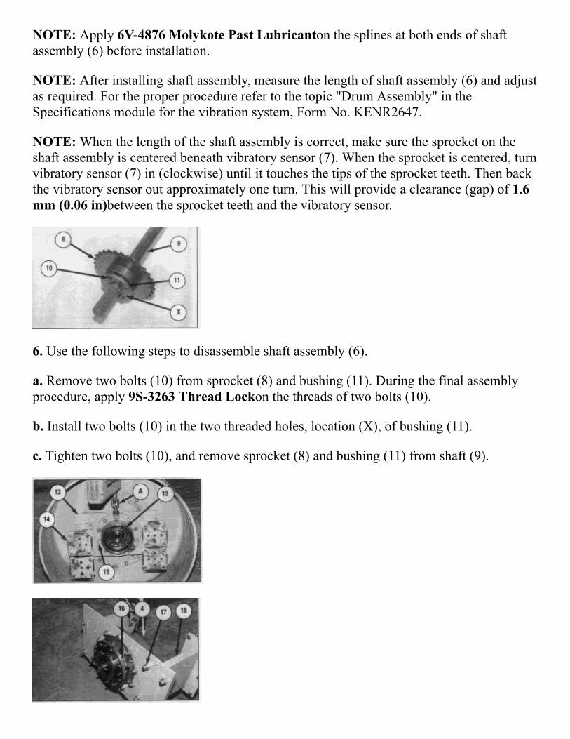
NOTE: When the length of the shaft assembly is correct, make sure the sprocket on theshaft assembly is centered beneath vibratory sensor (7). When the sprocket is centered, turnvibratory sensor (7) in (clockwise) until it touches the tips of the sprocket teeth. Then backthe vibratory sensor out approximately one turn. This will provide a clearance (gap) of 1.6mm (0.06 in)between the sprocket teeth and the vibratory sensor.
6. Use the following steps to disassemble shaft assembly (6).
a. Remove two bolts (10) from sprocket (8) and bushing (11). During the final assemblyprocedure, apply 9S3263 Thread Lockon the threads of two bolts (10).
b. Install two bolts (10) in the two threaded holes, location (X), of bushing (11).
c. Tighten two bolts (10), and remove sprocket (8) and bushing (11) from shaft (9).
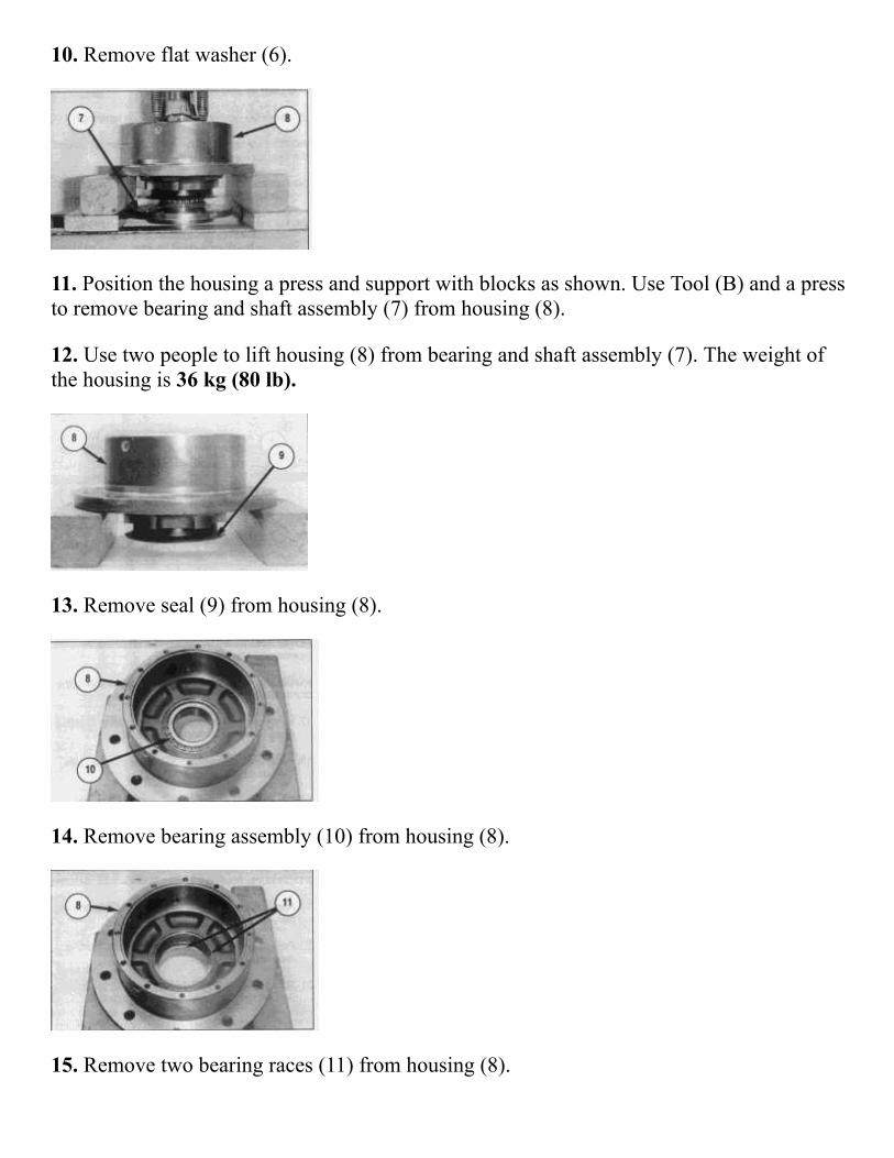
7. Remove one of the bolts that fastens drum support housing (13) and plate (12) together.Attach a suitable lifting bracket and Tool (A) as shown.
8. Remove eight bolts (16), and remove drum support housing (13) and plate (12) as a unitfrom the drum assembly. The weight of the drum support housing and plate as a unit isapproximately 130 kg (286 lb).When installing, apply 9S3263 Thread Lockon the threadsof eight bolts (16).
9. Lower the drum support housing and plate (12) to a level surface. While supporting thedrum support housing and plate, remove four bolts (17) and support (18) from both sides ofthe plate. The weight of each support is 30 kg (66 lb).
10. Remove the 16 bolts and four rubber mounts (14) from supports (10).
11. To prevent dirt from getting inside the drum support housing, install the 12 bolts andcover (4) on drum support housing (13). Position drum support housing (13) and plate (12)on cover (4).
12. Remove ten nuts and bolts (15) and Tool (A). Remove plate (12) from drum supporthousing (13). The weight of the plate is 22 kg (48 lb).The weight of the drum supporthousing is 73 kg (160 lb).
13. Remove rubber gasket (19) from the bearing housing on the drum assembly. Check therubber gasket for wear or damage and replace if necessary.
NOTE: For installation of the drum support housing, reverse the removal steps.
End by:
a. install drum assembly
NOTE: After the drum support housing has been installed, fill the housing with oil to thecorrect level. See the Operation & Maintenance Manual for the correct procedure.
Disassemble & Assemble Drum Support Housing (CS431C L.H. Side And CS431C, CP433C & CS433CR.H. Side)
Start By:
a. remove drum support housing
1. Make sure the outside of the drum support housing is clean and free of dirt and debris.
2. Put alignment marks on the housing and cover to aid in the assembly steps.
3. Install the drum support housing on a suitable stand or move to a clean flat area fordisassembly. The weight of the drum support housing is 73 kg (160 lb).
4. Remove twelve bolts (1).
NOTE: Every third bolt in the pattern has a lock washer and is slightly longer than theother bolts. Mark or identify for later installation.
5. Remove cover (2).
6. For the drum support housing, on the right hand side (CS413C, CP433C & CS433C),remove Oring (3). Check the Oring seal for wear or damage. Replace if necessary. For thedrum support housing on the left hand side (CS413C only) uses 9T9014 SiliconeSealantto seal the cover to the housing.
7. Bend tab on washer (5) away from corresponding slot in nut (4).
8. Use Tool (A) to remove retaining nut (4).
NOTE: During assembly, 9S6232 Thread Lockwas used on nut (4). To remove the nut, itmay be necessary to slightly heat nut (4).
9. Remove tab washer (5).
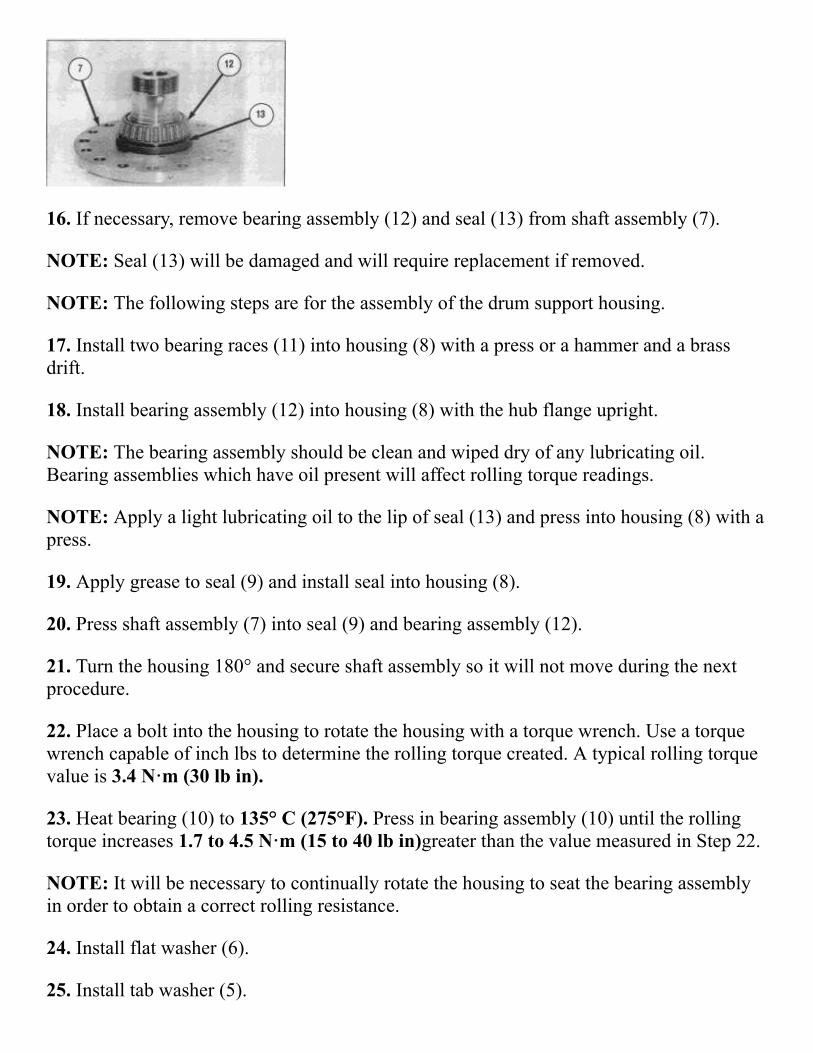
10. Remove flat washer (6).
11. Position the housing a press and support with blocks as shown. Use Tool (B) and a pressto remove bearing and shaft assembly (7) from housing (8).
12. Use two people to lift housing (8) from bearing and shaft assembly (7). The weight ofthe housing is 36 kg (80 lb).
13. Remove seal (9) from housing (8).
14. Remove bearing assembly (10) from housing (8).
15. Remove two bearing races (11) from housing (8).
16. If necessary, remove bearing assembly (12) and seal (13) from shaft assembly (7).
NOTE: Seal (13) will be damaged and will require replacement if removed.
NOTE: The following steps are for the assembly of the drum support housing.
17. Install two bearing races (11) into housing (8) with a press or a hammer and a brassdrift.
18. Install bearing assembly (12) into housing (8) with the hub flange upright.
NOTE: The bearing assembly should be clean and wiped dry of any lubricating oil.Bearing assemblies which have oil present will affect rolling torque readings.
NOTE: Apply a light lubricating oil to the lip of seal (13) and press into housing (8) with apress.
19. Apply grease to seal (9) and install seal into housing (8).
20. Press shaft assembly (7) into seal (9) and bearing assembly (12).
21. Turn the housing 180° and secure shaft assembly so it will not move during the nextprocedure.
22. Place a bolt into the housing to rotate the housing with a torque wrench. Use a torquewrench capable of inch lbs to determine the rolling torque created. A typical rolling torquevalue is 3.4 N·m (30 lb in).
23. Heat bearing (10) to 135° C (275°F). Press in bearing assembly (10) until the rollingtorque increases 1.7 to 4.5 N·m (15 to 40 lb in)greater than the value measured in Step 22.
NOTE: It will be necessary to continually rotate the housing to seat the bearing assemblyin order to obtain a correct rolling resistance.
24. Install flat washer (6).
25. Install tab washer (5).
26. Use Tool (A) to install retaining nut (4).
NOTE: Apply 9S3263 Thread Lockto the threads of nut (4).
27. Use Tool (A) and tighten retaining nut (4) to a torque of 306 N·m (225 lb ft).
28. Recheck the rolling torque. The final reading should be 1.7 to 4.5 N·m (15 to 40 lbin)greater than the value observed in Step 22.
NOTE: A final rolling torque of 5 to 7 N·m (45 to 65 lb in)should result in a bearingpreload of .0254 to .0508 mm (.001 to .002 in).
29. Bend tab washer (5) up into slot on retaining nut (4).
NOTE: If the tang does not line up, tighten nut (4) until the tang can be bent into the slot.
30. Release shaft assembly and remove bolt used for checking rolling torque.
31. For the drum support housing on the right hand side (CS431C, CP433C & CS433C),install Oring (3). For the drum support housing on the left hand side (CS431C only),apply a 3.2 mm (.125 in)continuous bead of 8T9014 Silicone Sealanton the mountingsurface of the housing where the cover fastens.
32. Position cover (2) in its original location.
33. Install twelve bolts (1). Place longer bolts and washers in their original locations.
End By:
a. install drum support housing
Disassemble Drum Assembly
Start By:
a. remove drum support housing (CS413C L.H. Side)
or
remove drum gear reducer (CS433C & CP433C)
b. remove drum support housing (CS431C, CP433C & CS433C R.H. Side)
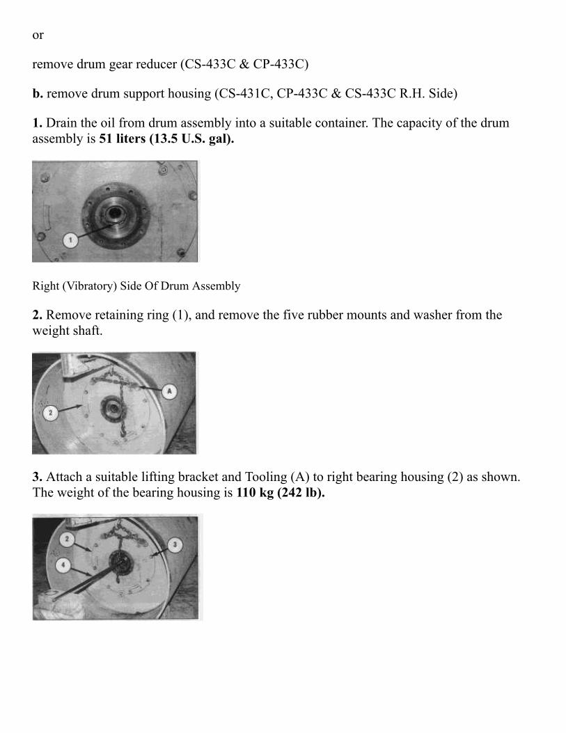
1. Drain the oil from drum assembly into a suitable container. The capacity of the drumassembly is 51 liters (13.5 U.S. gal).
Right (Vibratory) Side Of Drum Assembly
2. Remove retaining ring (1), and remove the five rubber mounts and washer from theweight shaft.
3. Attach a suitable lifting bracket and Tooling (A) to right bearing housing (2) as shown.The weight of the bearing housing is 110 kg (242 lb).
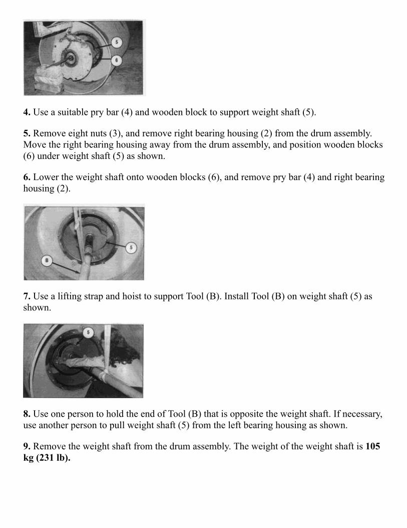
4. Use a suitable pry bar (4) and wooden block to support weight shaft (5).
5. Remove eight nuts (3), and remove right bearing housing (2) from the drum assembly.Move the right bearing housing away from the drum assembly, and position wooden blocks(6) under weight shaft (5) as shown.
6. Lower the weight shaft onto wooden blocks (6), and remove pry bar (4) and right bearinghousing (2).
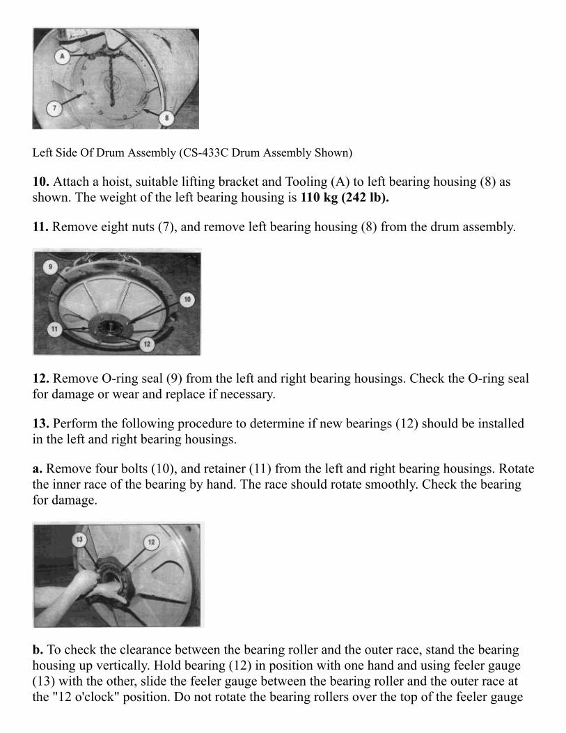
7. Use a lifting strap and hoist to support Tool (B). Install Tool (B) on weight shaft (5) asshown.
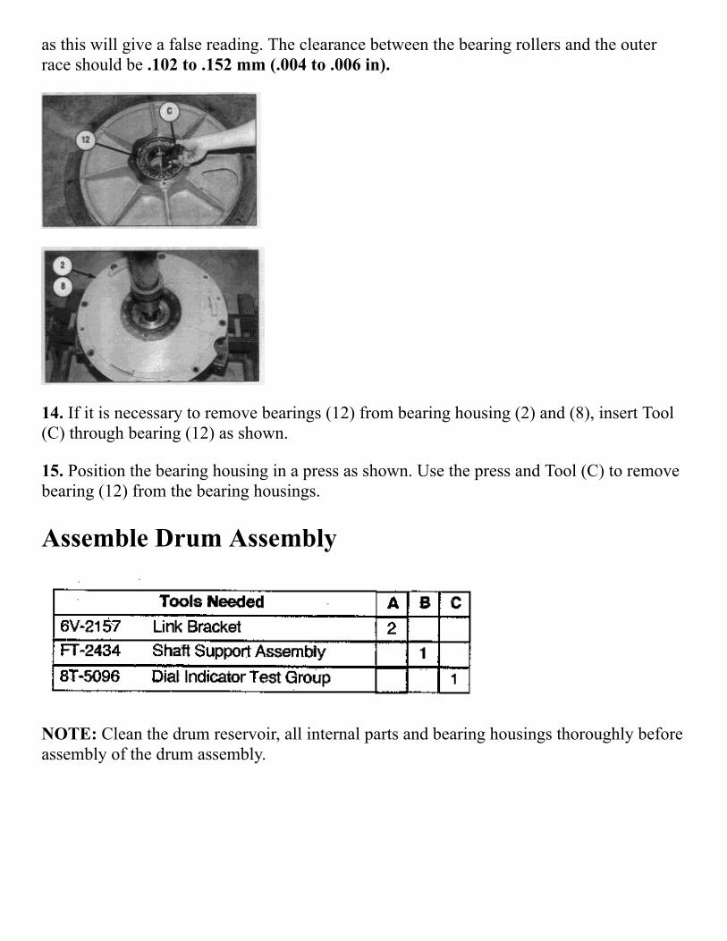
8. Use one person to hold the end of Tool (B) that is opposite the weight shaft. If necessary,use another person to pull weight shaft (5) from the left bearing housing as shown.
9. Remove the weight shaft from the drum assembly. The weight of the weight shaft is 105kg (231 lb).
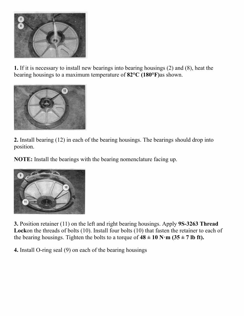
Left Side Of Drum Assembly (CS433C Drum Assembly Shown)
10. Attach a hoist, suitable lifting bracket and Tooling (A) to left bearing housing (8) asshown. The weight of the left bearing housing is 110 kg (242 lb).
11. Remove eight nuts (7), and remove left bearing housing (8) from the drum assembly.
12. Remove Oring seal (9) from the left and right bearing housings. Check the Oring sealfor damage or wear and replace if necessary.
13. Perform the following procedure to determine if new bearings (12) should be installedin the left and right bearing housings.
a. Remove four bolts (10), and retainer (11) from the left and right bearing housings. Rotatethe inner race of the bearing by hand. The race should rotate smoothly. Check the bearingfor damage.
b. To check the clearance between the bearing roller and the outer race, stand the bearinghousing up vertically. Hold bearing (12) in position with one hand and using feeler gauge(13) with the other, slide the feeler gauge between the bearing roller and the outer race atthe "12 o'clock" position. Do not rotate the bearing rollers over the top of the feeler gauge
as this will give a false reading. The clearance between the bearing rollers and the outerrace should be .102 to .152 mm (.004 to .006 in).
14. If it is necessary to remove bearings (12) from bearing housing (2) and (8), insert Tool(C) through bearing (12) as shown.
15. Position the bearing housing in a press as shown. Use the press and Tool (C) to removebearing (12) from the bearing housings.
Assemble Drum Assembly
NOTE: Clean the drum reservoir, all internal parts and bearing housings thoroughly beforeassembly of the drum assembly.
1. If it is necessary to install new bearings into bearing housings (2) and (8), heat thebearing housings to a maximum temperature of 82°C (180°F)as shown.
2. Install bearing (12) in each of the bearing housings. The bearings should drop intoposition.
NOTE: Install the bearings with the bearing nomenclature facing up.
3. Position retainer (11) on the left and right bearing housings. Apply 9S3263 ThreadLockon the threads of bolts (10). Install four bolts (10) that fasten the retainer to each ofthe bearing housings. Tighten the bolts to a torque of 48 ± 10 N·m (35 ± 7 lb ft).
4. Install Oring seal (9) on each of the bearing housings
NOTE: Before installing the bearing housings, make sure the oil reservoirs have beenthoroughly steam cleaned and tack cloth used during the final cleaning.
5. Use a hoist, suitable lifting bracket and Tooling (A) to position left bearing housing (8)on the drum assembly, and install eight nuts (7).
6. Apply 6V4876 Molycoat Paste Lubricanton the contact surfaces of weight shaft (5)and the bearing inside the left bearing housing.
7. Use a lifting strap and hoist to support Tool (B). Using one person to hold the end ofTool (B), install weight shaft (5) in the left bearing housing. Make sure the correct end ofweight shaft (5) is installed in the left bearing housing. If necessary, use another person topush weight shaft (5) into the left bearing housing as shown.
8. Position wooden blocks under weight shaft (5) as shown. Remove Tool (B) from theweight shaft.
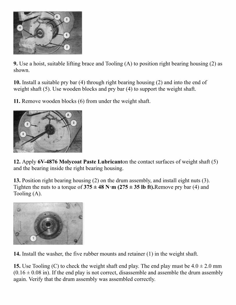
9. Use a hoist, suitable lifting brace and Tooling (A) to position right bearing housing (2) asshown.
10. Install a suitable pry bar (4) through right bearing housing (2) and into the end ofweight shaft (5). Use wooden blocks and pry bar (4) to support the weight shaft.
11. Remove wooden blocks (6) from under the weight shaft.
12. Apply 6V4876 Molycoat Paste Lubricanton the contact surfaces of weight shaft (5)and the bearing inside the right bearing housing.
13. Position right bearing housing (2) on the drum assembly, and install eight nuts (3).Tighten the nuts to a torque of 375 ± 48 N·m (275 ± 35 lb ft).Remove pry bar (4) andTooling (A).
14. Install the washer, the five rubber mounts and retainer (1) in the weight shaft.
15. Use Tooling (C) to check the weight shaft end play. The end play must be 4.0 ± 2.0 mm(0.16 ± 0.08 in). If the end play is not correct, disassemble and assemble the drum assemblyagain. Verify that the drum assembly was assembled correctly.
NOTE: The drum assembly must be flushed before oil is added. Refer to the topic "DrumFlushing Procedure" in Special Instruction, SEHS9880.
NOTE: Fill the drum assembly with oil to the correct level. See the Operation &Maintenance Manual for the correct filling procedure.
End By:
a. install drum support housing (CS431C L.H. Side)
or
install drum gear reducer (CS433C& CP433C)
b. install drum support housing (CS413C, CP433C & CS433C R.H. Side)
Copyright 1993 2016 Caterpillar Inc.All Rights Reserved.Private Network For SIS Licensees.
Fri Dec 09 2016 15:13:43 GMT0500 (Eastern StandardTime)