PERPETUUS TIDAL ENERGY CENTRE CABLE IN OUTFALL PIPE THERMAL RATING STUDY Author: Theo Spanellis, Martin Hird Verifier(s): Nigel Scott, Jeff Fodiak Approver: Nigel Scott ISSUED 27 MAY 2014 REP 1335/003/001B PREPARED FOR IT POWER
Transcript
PERPETUUS TIDAL ENERGY CENTRE
CABLE IN OUTFALL PIPE THERMAL RATING STUDY
Author: Theo Spanellis, Martin Hird
Verifier(s): Nigel Scott, Jeff Fodiak
Approver: Nigel Scott
ISSUED 27 MAY 2014 REP 1335/003/001B
PREPARED FOR IT POWER
Xero Energy Limited REP 1335/003/001B
i
DOCUMENT HISTORY
V AUTH VERF APPR DATE NOTES
A TS NCS, JSF NCS 24/04/2014 First issue assessing continuous current cable ratings.
B MH NCS, JSF NCS 27/05/2014 Updated to include a rating assessment taking into account the cyclic nature of the generation at PTEC.
NOTES
This document and any accompanying documents are to be distributed to members within the named client organisation only and are not to be distributed to other third parties or the public without express written consent from Xero Energy Limited. Xero Energy Limited does not accept responsibility for the application or use made of information or advice supplied. Such responsibility remains with the client. Enquiries should be directed to Xero Energy Limited, 60 Elliot Street, Glasgow G3 8DZ, UK.
Xero Energy Limited Registered as No. SC313697 in Scotland at 60 Elliot Street, Glasgow G3 8DZ
Xero Energy Limited REP 1335/003/001B
ii
TABLE OF CONTENTS
Document History .................................................................................................................. i Notes ..................................................................................................................................... i Table of Contents .................................................................................................................. ii Acronyms ............................................................................................................................. iv Executive Summary ............................................................................................................... v 1 Introduction .................................................................................................................. 1
1.1 General .................................................................................................................. 1 1.2 Scope and approach ............................................................................................... 1 1.3 Report layout ......................................................................................................... 2
2 Methodology ................................................................................................................. 3 2.1 Introduction ........................................................................................................... 3 2.2 XLPE AC cable design and technical characteristics ................................................. 3 2.3 Steady state current rating of AC cables ................................................................. 4 2.4 Cyclic current rating of AC cables ........................................................................... 5
4.3.1 Ground outside the concrete pipe ................................................................ 10 4.3.2 Air inside the concrete pipe .......................................................................... 10
4.4 Installation cases .................................................................................................. 11 4.4.1 General ........................................................................................................ 11 4.4.2 Cables in ducts ............................................................................................. 11 4.4.3 Cables without ducts .................................................................................... 12
4.5 Burial depth ......................................................................................................... 12 4.6 Derating due to additional circuits ....................................................................... 12 4.7 Cable installation modelling ................................................................................. 13
4.7.1 Steady state ................................................................................................. 13 4.7.2 Cyclic ............................................................................................................ 14
5 Operational assumptions ............................................................................................. 15 5.1 Power output ....................................................................................................... 15 5.2 Voltage ................................................................................................................ 15 5.3 Power factor ........................................................................................................ 15 5.4 Steady state current flow in each cable ................................................................ 15 5.5 Cyclic current flow in each cable .......................................................................... 16
7 General discussion ....................................................................................................... 21 7.1 Uncertainty and assumptions ............................................................................... 21
7.1.1 Material surrounding the concrete pipe ....................................................... 21
Xero Energy Limited REP 1335/003/001B
iii
7.1.2 Concrete pipe burial depth ........................................................................... 21 7.1.3 Current flow in the cables............................................................................. 21 7.1.4 Convective air flows in the concrete pipe ..................................................... 22
IEEE Institute of Electrical and Electronic Engineers
ITP IT Power Limited
K Kelvin
km Kilometre
kV Kilovolt
m Metre
mm Millimetre
MW Megawatt
PE Polyethylene
PTEC Perpetuus Tidal Energy Centre
RMS Root Mean Square
W Watt
XE Xero Energy Limited
XLPE Cross-Linked Polyethylene
°C Degree Celsius
Ω Ohm
Xero Energy Limited REP 1335/003/001B
v
EXECUTIVE SUMMARY
Xero Energy Limited (XE) has been commissioned by IT Power Limited (ITP) to perform preliminary current rating calculations for the export cables of the Perpetuus Tidal Energy Centre (PTEC), should they be installed in a concrete water outfall pipe at landfall. PTEC is planned for an output of 30MW via six 11kV and/or 6.6kV three-core subsea cables to the onshore substation. The aim of this study is to determine the feasibility of installing the proposed six cables through the concrete water outfall pipe, considering the thermal interaction between the cables and their installed conditions. XE has examined two installation cases for the cables, one where the six cables are pulled directly into the pipe, and one where they are pulled through individual ducts (one for each cable). XE has assumed a power factor of 0.95 at nominal voltage of 11kV for all six cables, and a steady state current of 276A in each cable. XE has assumed a burial depth of 1m in total, and a soil thermal resistivity of 1K∙m/W, representative of the different mix of materials around the concrete pipe. XE has treated the cables as a bank directly buried in soil, and used a range of thermal resistivities from 2.5K∙m/W to 6K∙m/W to represent the air inside the outfall pipe. XE has examined the ratings for 11kV copper three-core cables for conductor sizes from 240mm2 to 500mm2. XE has calculated the steady-state cable ratings according to IEC 60287 and the cyclic cable ratings according to IEC 60853 Part 1. The cyclic cable rating reflects the additional rating that is gained based on the cyclic variation of generator output. The results are summarised in the table below.
Cable size [mm2]
Thermal resistivity of
air in pipe [K∙m/W]
Cable conductor temperature [°C]
Steady state Cyclic
Cables in ducts
Cables without ducts
Cables in ducts
Cables without ducts
240
1.0 100.0 105.0 67.3 69.6
2.5 110.0 120.0 73.0 78.3
6.0 136.2 164.3 86.9 100.1
300
1.0 86.4 88.0 60.0 60.4
2.5 94.7 99.4 64.8 67.1
6.0 115.0 128.3 76.4 83.2
400 2.5 72.8 75.2 51.4 52.5
6.0 87.0 94.4 59.7 63.7
500 2.5 63.4 64.4 45.9 46.2
6.0 74.8 79.0 52.8 55.1
The steady state results show that the intended 240mm2 cable is inadequate, so larger cable sizes of up to 500mm2 will have to be used. The larger cable size might be an issue with pulling the cables through the ducts. The cyclic results show that the 240mm2 cable size is marginal / inadequate, but the 300mm2, 400mm2 and 500mm2 cables appear to be adequately rated. The results also show that the installation without ducts is the less thermally favourable option. It should be noted that there is significant uncertainty in the installation conditions of the pipe and the cable modelling, particularly with the convective heat transfer of the air in the pipe. XE therefore suggests selecting a cable size larger than would appear necessary and building in additional protective measures such as a temperature sensing system. XE recommends that the study is revisited once more accurate data on the burial depth, ground conditions and thermal resistivity are available. Alternative modelling methods should be explored to verify the results in this report if reasonably practicable to do so, and, the ultimate cable supplier should undertake its own calculations and be required to warrant the cables in the pipe.
Xero Energy Limited REP 1335/003/001B
Page 1 of 30
1 Introduction
1.1 General
Xero Energy Limited (XE) has been commissioned by IT Power Limited (ITP) to perform preliminary current rating calculations for the export cables of the Perpetuus Tidal Energy Centre (PTEC) should they be installed in a water outfall pipe at landfall. The aim is to determine the feasibility and specification of installing the proposed six subsea feeder cables from PTEC to the proposed project onshore substation through a concrete water outfall pipe at the landing point considering the thermal interaction between the cables and their installed conditions. This work has been undertaken as thermal interaction can be expected to be significant and will have a significant impact on cable rating and sizing. PTEC is currently proposed to consist of six berths for connecting and testing tidal devices, with each berth not exceeding 6MW capacity, even though this might increase in the future. The proposed total project output will not exceed 30MW.
1.2 Scope and approach
In this report XE has considered a base cable size assumed to be three-core 240mm2 copper conductor single armour type in accordance with guidance provided by ITP [1, 2]. XE has then assessed two installation scenarios and the impact they have on cable rating and cable size as follows:
Firstly, a scenario where the six cables are laid directly within the concrete outfall pipe and will rest on each other.
Secondly, a scenario where the six cables are laid within the concrete outfall pipe using ducts, one for each cable, to potentially ease cable installation issues.
The above calculations have then been repeated for larger cable sizes, if needed (should the cable rating prove to be inadequate), to assess the actual cable size required. Increasing cables sizes does however increase both cable supply costs and installation costs. The study work for revision A of this report has been based on continuous current ratings as set out in International Electrotechnical Commission (IEC) standard 60287 [3]. Revision B has extended the study to include cyclic current ratings, following the method of IEC standard 60853 Part 1 [4]. Aside from the above, key issues that impact on cable rating include the following:
The depth of burial of the concrete water outfall pipe. In general increased burial depth leads to lower ratings.
The surrounding backfill material (e.g. concreting and ground) and its ambient temperature.
The treatment of the free air in the concrete water outfall pipe. This will transfer heat by convection which significantly complicates the rating assessment which would normally be based on conductive effects.
These are all discussed in the report in the following sections.
Xero Energy Limited REP 1335/003/001B
Page 2 of 30
1.3 Report layout
This report is organised with the following layout:
Section 1 Introduction
Section 2 Methodology
Section 3 Cable assumptions
Section 4 Installation assumptions
Section 5 Operational assumptions
Section 6 Cable ratings results
Section 7 General discussion
Section 8 Summary
Section 9 Recommendations
Xero Energy Limited REP 1335/003/001B
Page 3 of 30
2 Methodology
2.1 Introduction
For the cable current rating calculations, XE has first used a typical manufacturer’s cable manual [5], along with de-rating factors for installation conditions that are commonly given by cable manufacturers. This has been done to get a quick view of the likely impacts, and a starting point for more detailed calculations. XE has then used the IEC international standard 60287: “Electric cables – calculation of the current rating” [3] and associated relevant parts to calculate the cable conductor temperature that would occur due to each cable carrying steady state rated current. This then dictates the cable rating. Following this, XE has used IEC standard 60853 Part 1 [4] to calculate the cyclic rating factor, which is a ratio that is used to adjust the steady state rating due to cyclic cable current. This would typically allow smaller cable sizes to be used when currents are not continuous at rated values as is the case for PTEC. The methods used are described in the following sections.
2.2 XLPE AC cable design and technical characteristics
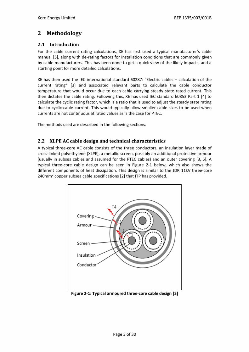
A typical three-core AC cable consists of the three conductors, an insulation layer made of cross-linked polyethylene (XLPE), a metallic screen, possibly an additional protective armour (usually in subsea cables and assumed for the PTEC cables) and an outer covering [3, 5]. A typical three-core cable design can be seen in Figure 2-1 below, which also shows the different components of heat dissipation. This design is similar to the JDR 11kV three-core 240mm2 copper subsea cable specifications [2] that ITP has provided.
A key factor that drives the current rating of a cable is the CSA of the conductor. Cables with larger conductor sizes have less resistance and thus fewer losses (equal to Ι2·R). The losses generate heat within the cable. There is a limit to how much heat the elements of the cable can be exposed to during continual operation, based on the maximum temperature specification of the cable insulation. This defines the current rating of the cable. The resistance of the conductor is also affected by the conductor material, but this has a smaller effect, since the typical conductor materials are either copper or aluminium. XE has assumed copper conductor cables for this study, according to the subsea cable’s specification documents used [3]. Another factor that influences the rating of the cable is the screen CSA and corresponding screen sheath thickness. The wire screen affects the cable rating due to the currents induced in the screen, which increase the temperature of the conductor, and therefore reduce its current carrying capacity. The cable armouring also has a similar impact on cable rating, which can be more significant. However, the screen size and the armour thickness tend to be standard, for each cable size, and only change to provide additional mechanical support and protection. Therefore, they have not been considered as a factor in this study. Other technical characteristics, such as the insulation material and thickness, and the outer covering thickness, also influence the current rating of the cable, but to a much smaller degree. They determine how the heat is transferred from the conductor to the outside environment, through the thermal resistances of the insulation (T1), the sheath bedding (T2), the outer covering (T3) and the ground (T4) [3], as can be seen in Figure 2-1. A high thermal resistance of a cable component means a higher temperature rise and lower current rating.
2.3 Steady state current rating of AC cables
IEC 60287 offers the full method of calculating the permissible steady state current through a cable, taking into account factors such as cable layout, installation conditions, skin effect, and eddy and circulating current losses etc. The formula for the temperature rise due to the current flowing is given in [3] as:
Where Δθ : the conductor temperature rise above the ambient temperature (K) Wd : the dielectric loss per unit length for the insulation (W/m) R : Alternating Current (AC) resistance of the conductor at operating temperature (Ω/km) T1 : thermal resistance between one conductor and the sheath (K∙m/W) T2 : thermal resistance of the bedding between sheath and armour (K∙m/W) T3 : thermal resistance of the external serving of the cable (K∙m/W) T4 : thermal resistance between the cable surface and the surrounding medium (K∙m/W) n : the number of load-carrying conductors in the cable λ1,λ2 : the ratio of losses in the metal sheath and armour to total losses in the conductors
The factor Δθ is essentially the difference between the maximum permitted operating temperature of the conductor (90°C for the assumed cables) and that of the environment (assumed here to be 15°C, as per common practice in the UK).
Xero Energy Limited REP 1335/003/001B
Page 5 of 30
2.4 Cyclic current rating of AC cables
IEC 60853 Part 1 [4] provides methods for calculating the current rating of cables with operating voltages up to 33kV, when the current varies cyclically over a twenty-four hour period, the shape of each daily cycle being substantially the same. The method calculates a ‘cyclic rating factor’, which is a factor greater or equal to 1.0 by which the steady state current rating can be multiplied to obtain the cyclic rating. The cyclic rating represents the allowable peak current during a daily cycle, such that during this cycle the conductor reaches, but does not exceed, the maximum permissible operating temperature (usually 90°C for XLPE insulated cables). The method first divides a typical daily current cycle into twenty-four one-hour steps. The time of highest cable temperature within this twenty-four hour cycle is then selected by observation and is usually at the end of the period of highest current. The cable temperature at this time is calculated taking into account the current values during the six one-hour steps preceding this time and an average current for the whole twenty-four hour cycle. The standard provides methods for taking account of various cable installation arrangements, including groups of buried cables or ducts. This method has been used for the installation of the six cables in ducts and without (i.e. not in) ducts, within the water outfall pipe at landfall for the PTEC project. Details of the installation arrangements are given in Section 4.4. The IEC standard states that it applies to cables or ducts buried in uniform soil. Its application to the installation of cables within an outfall pipe should therefore be treated with some caution because the standard does not readily take into account the effect of air within the outfall pipe. This is discussed further in Section 4.7.
Xero Energy Limited REP 1335/003/001B
Page 6 of 30
3 Cable assumptions
3.1 Introduction
This section reviews the construction of the cable and the cable parameters used in the study. ITP has provided a set of cable drawings from JDR [2]. However, as the exact JDR cable specifications are not available, XE has based this study of the PTEC cables on the technical characteristics of Nexans XLPE AC subsea cables, as extended documentation and technical details are available [5]. For modelling the existing PTEC cables, XE has also used the Nexans technical characteristics, making informed assumptions for the various cable components, when this was not available. XE notes that manufacturers’ cables are similar, but the results will vary slightly with the manufacturer’s exact specifications. Along with the set of cable drawings, a single-line diagram of the intended electrical connection [6] and a set of schematic diagrams of the water outfall pipe were provided by ITP [7], the most relevant being the ‘FlowersBrook 53.20’ drawing [8]. A list of the key parameters used can be seen in Appendix A. XE has based this study on these specifications and has made suitable assumptions where data was incomplete. These assumptions have been based on XE’s knowledge of power cables, discussion with cable manufacturers and good engineering practice.
3.2 Conductor
Data for the 240mm2 copper conductors planned to be used, along with larger cable sizes used for comparison, is given in Table 3-1 below. XE has examined the following cable sizes for PTEC.
Conductor CSA [mm2]
Conductor diameter [mm]
DC resistance at 20°C [Ω/km]
240 18.6 0.0754
300 20.6 0.0601
400 23.8 0.0470
500 26.6 0.0366
Table 3-1: Conductor parameters
The diameter of the conductor is not directly calculated from the CSA, due to the fact that the conductor is normally stranded, with small gaps between the strands. This results in a larger actual diameter than would be otherwise calculated from the CSA. Nexans’ documentation [5] gives the actual diameter of each conductor size, and also the conductor DC resistance (at 20°C) values for copper conductors based on data given in IEC 60228 [9].
Xero Energy Limited REP 1335/003/001B
Page 7 of 30
3.3 Insulation
The insulation material most commonly used for AC cables is triple extruded XLPE. XLPE insulation has a nominal thermal resistivity of 3.5K∙m/W according to IEC 60287 [3], but is known to reach lower values. XE has used a nominal thermal resistivity value of 3.5K∙m/W at 90°C operation for the XLPE insulation of the AC cables. XE has also used a total insulation thickness of 3.4mm for the 6/10(12)kV nominal voltage class cables as quoted in the Nexans data for AC XLPE cables [5].
The assumed cables use a thin copper tape screen, directly above the insulation of each conductor (note that the JDR cables specified by ITP have a copper wire screen). The effect of the screen bedding thickness to the cable thermal resistivity (and therefore to the cable current rating) is almost negligible, whether wire or tape. However, the screen itself presents circulating and eddy current losses, thus affecting the current rating of the cable. The copper screen according to the Nexans specifications [5] has a cross-sectional area of 25mm2 to 35mm2 for the examined cable, and XE has used these values in the calculations. XE has assumed a screen bonded at both ends, as described in [5], which results in some circulating currents, but effectively negligible eddy currents in the screen. The cable armour consists of galvanized round steel wires of 4.2-5mm diameter, and surrounds all three conductors with their screens.
Conductor CSA [mm2]
Screen CSA [mm2]
Armour wire diameter
[mm]
240 25 5
300 25 4.2
400 35 4.5
Table 3-2: Screen and armour parameters
The thickness of the outer covering is given as 4mm for all examined cable sizes [5].
3.5 Design temperature
The design temperature refers to the conductor temperature limit which the cable can be continuously loaded to without reducing the design life of the cable. This is determined by the insulation material, which could see performance degradation or failure at critical temperatures. For AC cables with XLPE insulation, the maximum temperature is typically 90°C, which is the design operating temperature that Nexans also specifies [5] and XE has assumed.
Xero Energy Limited REP 1335/003/001B
Page 9 of 30
4 Installation assumptions
4.1 Introduction
This section discusses the conditions and factors relevant to the installation of the cables. XE has examined two different installation methods for the cables inside the water outfall pipe as follows.
Cables laid directly inside the concrete water outfall pipe.
Cables laid in separate ducts inside the concrete water outfall pipe.
‘Laid directly’ and ‘in separate ducts’ refers to the installation arrangement, which is discussed in Section 4.4. Other factors that influence the cable rating are discussed in the following sections, along with the assumptions that XE has made. XE has assumed the ducted case due to concerns over the practicality over pulling cables through the pipe and the risk of cable damage.
4.2 Ground temperature
The ground (ambient) temperature normally refers to the medium which the cables are buried in, but in this case it specifically refers to the ground conditions outside the water outfall pipe. The ground temperature is determined by its thermal conductivity, thermal diffusivity, volumetric heat capacity, and the temperatures it is exposed to (the local climate). XE has used 15°C which is a reasonable and common assumption for the location of the project, as it is also commonly used for cable installations in the UK. Note that higher ground temperatures will reduce the rating of the cable.
4.3 Ground thermal resistivity
The thermal resistivity of the material around the cables has a significant effect on the cable rating, as it defines the rate of heat dissipation from the cables to the outside environment, and hence the temperature rise of the cables. In general, materials with higher thermal resistivity will drive the cable temperature up and cable current rating down as they represent poor conductors of heat. Table 4-1 contains common thermal resistivity values for mediums relevant to the PTEC case.
Surrounding material Thermal resistivity
[K∙m/W]
Concrete 0.7 - 1.7
Steel reinforced concrete 0.5
Stabilised backfill / good soil 1.2
Stones & ballast 1.5
Chalk 11.1
Still air 41.0
Table 4-1: Commonly used thermal resistivity values
Xero Energy Limited REP 1335/003/001B
Page 10 of 30
4.3.1 Ground outside the concrete pipe
The ground outside of the concrete pipe dissipates heat from the pipe to the ground surface. Typical thermal resistivity values for soil range from 1K∙m/W for moist soils to 4K∙m/W for extremely dry soils. For the purposes of this study, XE has assumed the value for the ground thermal resistivity to be 1K∙m/W as this is broadly representative of the backfill around the concrete pipe construction and the wider geotechnical conditions which are expected to be a mix of chalk, stones and ballast. XE suggests this study can be revisited if thermal resistivity tests are carried out, where possible, on the soil in the area and the material around the pipe.
4.3.2 Air inside the concrete pipe
The PTEC cables are enclosed in a concrete pipe that is largely air-filled once it rises out of the sea. As noted above, air is a very poor conductor of heat and cables in air-filled ducts or similar air-filled environments are normally significantly de-rated. The IEC standards deal with air-filled ducts as this is a common arrangement. However, larger air volumes are more challenging and currently not within the scope of the IEC standards. XE has therefore extended the IEC method using test cases and appropriate reference material to model the effect of the air in the concrete outfall pipe. Still air has a thermal resistivity of around 41K∙m/W, which is very high and would significantly de-rate the cables. However, the situation within ducts is far more complicated than this as the primary method of heat transfer is not conduction but convection due to the air, plus some amount of replacement air circulation, especially for large ducts, like the concrete outfall pipe. There is also some conduction and radiation but overall these effects are smaller. To reasonably model the conditions in the concrete pipe, XE has modelled the convective heat transfer as an equivalent thermal resistance, with reference to various published work, to establish a likely bracket of values the cables will ultimately be rated within. This is described in Section 4.7 below.
Xero Energy Limited REP 1335/003/001B
Page 11 of 30
4.4 Installation cases
4.4.1 General
As mentioned in Section 4.1, there are two general installation methods examined, both involving laying six 11kV subsea armoured cables inside the concrete water outfall pipe.
4.4.2 Cables in ducts
The installation case of ‘cables in ducts’ involves installing ducts inside the water outfall pipe, one for each cable, through which the cables can be pulled separately. A schematic diagram of the cable and duct arrangements inside the pipe can be seen in Figure 4-1 below which shows a section where the water outfall pipe exits to the sea.
Figure 4-1: Installation of cables in individual ducts
Note that for a cable diameter of 99mm and a concrete pipe of an average diameter of 600mm, XE has indicatively established that a duct size of 180mm should be large enough to allow the cables to be pulled easily inside it and small enough for six such ducts to fit inside the pipe. XE has also assumed polyethylene (PE) ducts, which can be flexible and therefore can more easily be installed through the bends of the concrete pipe. Pulling cables in ducts is an installation method that XE considers may be necessary to allow practical installation without cable damage. It is common practice to use one duct per cable as this eases cable pulling operations, helps to avoid damage during cable pulling, and assists in retaining cable current ratings. However, cables in ducts tend to have lower ratings, e.g. an indicative 90%, of the rating of a single directly buried cable. This is mainly due to the air inside the duct, surrounding the cable, which is a bad conductor of the heat emitted by the cable, compared to the ground. However with groups of cables the impact of ducting is not always clear. Use of ducts can sometimes provide better ratings than unducted cable groups, primarily because the ducts separate the cables and stop them touching each other. For this study it is assumed the ducts only contain air as the insulating medium. However, ITP could consider using a duct backfill material with good thermal conductivity such as bentonite, if the cable ratings prove to be insufficient.
Xero Energy Limited REP 1335/003/001B
Page 12 of 30
4.4.3 Cables without ducts
For the installation case of ‘cables without ducts’, the cables are laid directly into the concrete pipe. It is assumed that the cables would bundle for most of the laying length, instead of lying neatly on the bottom of the pipe. This is illustrated in Figure 4-2 below.
Figure 4-2: Installation of cables without ducts
4.5 Burial depth
According to drawings provided by ITP, the water outfall pipe has a minimum thickness of 300mm on the top, and is covered by a layer of rocks with a minimum thickness of 500mm. No definite data has been provided on the burial depths along the whole pipe route, so an indicative depth had been assumed. Based on the above, XE has assumed an average 1m of depth from the top the pipe to the surface. This amounts to an average burial depth of 1300mm for the cables, measured to the centre of the pipe, for the purposes of the rating calculations according to the selected model, described in Section 4.7, actual depths varying between 1600mm and 1000mm, and being more than 1300mm for the case with no ducts. XE notes that cable current ratings decrease as burial depth increases, i.e. the cable current rating at 2m depth will be less than when the cable is buried at 1m depth. This means that this cable rating study should be revisited once more detailed information on depth is known, so that the worst case can be established and examined.
4.6 Derating due to additional circuits
A second cable, installed in close proximity to the first one (e.g. in the same trench or duct) acts as an additional external heat source. This increases the ambient temperature around the cable, reducing the allowable temperature rise and lowering the current rating of the cables in both circuits (see Equation 1). This effect is referred to as mutual heating between cable groups. Adding additional circuits increases this effect and further decreases the cable ratings. The six cables installed very close to each other will lead to serious mutual heating effects.
Xero Energy Limited REP 1335/003/001B
Page 13 of 30
4.7 Cable installation modelling
4.7.1 Steady state
XE notes that the IEC standard on cable ratings examines cases of one cable per duct, but not multiple cables in one duct or the case of multiple ducts inside a much larger duct (in this case the concrete pipe). XE has therefore developed and used a calculation method, based on the general principles regarding the transfer of heat as set out in the IEC standard, to estimate the cable temperature rise and thermal rating for cables and ducts inside a much larger common duct (i.e. concrete pipe). XE has assumed that in each case the cables or ducts are laid inside a bank filled with a backfill with a suitable range of thermal resistivity values so that the thermal transfer capability is equivalent to that of the air inside the concrete pipe. This bank represents the inside of the concrete pipe, and is surrounded by the concrete and soils external to the pipe, which in this case is considered the surrounding material, with a thermal resistivity, ρΤ, of 1K∙m/W. This is illustrated in Figure 4-3 below.
Figure 4-3: Model of ducts/cables inside the concrete pipe
The thermal rating calculations of a cable in a bank, and the mutual derating effects of multiple cables are covered in the IEC standard. The only approximation is in establishing an appropriate thermal resistance for the fill of the assumed bank (i.e. air within the concrete pipe), so that the cable will have the same rating as if it was inside the pipe, with the bank dimensions equal to the pipe diameter. XE has established that a thermal resistance value range of 2.5K∙m/W to 6.0K∙m/W can adequately represent the presence of air in the case of ducted cables, and possibly lower values of 2.0K∙m/W to 3.5K∙m/W in the case of non-ducted cables. This method is therefore not a calculation method within IEC 60287, but is derived from the IEC standard.
Xero Energy Limited REP 1335/003/001B
Page 14 of 30
4.7.2 Cyclic
IEC 60853 Part 1 [4] states that it applies to cables or ducts buried in uniform soil and so does not provide for variable soil thermal resistivity, such as within and outside a duct bank as described in Section 4.7.1. However, given the uncertainty in the thermal resistivity used to model the air inside the outfall pipe, it is not possible to accurately calculate the cable ratings for this case using IEC 60287 [3]. Therefore, an approximate value of cyclic rating factor is sufficient for this case. XE therefore considers it reasonable to calculate the cyclic rating factor for a range of soil thermal resistivity values, considering the thermal resistivity values within the duct bank and outside the duct bank, as described in Section 4.7.1, to be equal. The cyclic rating factor has been calculated in this way for a range of thermal resistivities from 1.0K∙m/W to 3.0K∙m/W. These thermal resistivities have been sufficient to calculate the possible range of cyclic rating factors.
Xero Energy Limited REP 1335/003/001B
Page 15 of 30
5 Operational assumptions
5.1 Power output
PTEC’s output is expected to be 30MW, divided into six berths for the connection of tidal generators, each with its own cable to connect to the onshore substation. XE has therefore assumed each cable will carry up to 5MW at 11kV.
5.2 Voltage
The connection nominal voltage is planned to be 11kV and 6.6kV, with most likely two cables operating at 6.6kV and four cables at 11kV, according to ITP [10]. All cables are expected to be rated for operation at 11kV. At the onshore substation, ITP has proposed that the power will be transformed to 33kV via a 33/11kV and a 33/6.6kV transformer (or a single 33/11/6.6kV transformer). These are to be equipped with tap-changers, which will allow for a quite strict voltage control very close to the nominal levels. However, the voltage might not remain at a nominal value of 11kV or 6.6kV at all points of operation, and some voltage variations up or down should be expected. In lieu of a detailed specification for the onshore voltage control XE has assumed nominal voltage.
5.3 Power factor
PTEC would ideally operate with a unity power factor to minimise losses. However, given the unknown nature of the machines to be connected, and the length of the subsea cables which tend to generate reactive power, XE expects PTEC to operate at a slightly off-unity power factor. For the purposes of this study, XE has assumed a power factor of 0.95, which is a quite typical limit for renewable generators. XE notes, however, that the results will vary with the actual power factor of each cable, with better ratings achieved for power factors closer to unity.
5.4 Steady state current flow in each cable
To avoid adding any more complexity to the model used for the rating calculations, XE has opted to assume that all six cables will be the same, and equally loaded. To achieve this, and as described above, XE has assumed that all cables will be operating at 11kV, with a load of 5MW each. Taking into account a power factor of 0.95, XE estimates that the maximum current expected to flow in each cable under these assumptions will be 276.2A. Note that this current value is correct for 11kV cables operating at 5MW each, but corresponds to an output of 3MW for the 6.6kV cables.
XE has assumed a maximum current of 276.2A in each cable, corresponding to 5MW at 11kV (or to 3MW at 6.6kV).
Xero Energy Limited REP 1335/003/001B
Page 16 of 30
5.5 Cyclic current flow in each cable
ITP has provided projected power output data for PTEC [11]. This has been analysed to determine the twenty-four hour period with the highest average power. This is shown in Figure 5-1 below.
Figure 5-1: Highest projected PTEC power output during a 24 hour period [11]
As noted in Section 5.4, each cable has been assumed to carry identical current and so the maximum power output of 30.7MW in Figure 5-1 corresponds to a power of 5.12MW for each of six cables. In order to maintain compatibility with the steady state results of revision A of this report, a maximum power output of 5MW and so a maximum current 276.2A per cable have been assumed for the cyclic cable rating calculations. For use in the cyclic calculations, the power values shown in Figure 5-1 have been normalised and squared. Following the method outlined in Section 2.4, the time of highest cable temperature is hour 11 in Figure 5-1 and so the values at hours 6 to 11 have been considered in the cyclic rating calculations together with the average value over hours 0 to 23. For the cyclic power output shown in Figure 5-1, the peak value is 1.31 times the Root Mean Square (RMS) value. The RMS value is a good first approximation for the steady state power output that would provide the same cable heating as the cyclic power output shown in Figure 5-1.
Xero Energy Limited REP 1335/003/001B
Page 17 of 30
6 Cable ratings results
6.1 Introduction
XE has used the methodology described in Section 2, together with the cable model described in Section 4.7, to estimate the steady state and cyclic ratings of the cables. The following sections present the steady state cable ratings first, then the cyclic rating factors and cyclic cable ratings. The initial calculations for the proposed cable size of 240mm2 show a rating below the expected current flow and XE has therefore examined the next cable sizes up, i.e. 300mm2, 400mm2 and 500mm2 conductor sizes. XE has used the following colour code as set out in Table 6-1 to illustrate the adequacy of cable ratings:
Grade Adequacy of cable rating
L Adequate rating – cable temperature not expected to exceed 85°C
M Adequate but marginal rating – cable temperature exceeds 85°C but is less than 90°C – some risk of overheating issues
H Inadequate rating – cable temperature exceeds 90°C – significant risk of overheating
Table 6-1: Colour coding of cable rating adequacy
Xero Energy Limited REP 1335/003/001B
Page 18 of 30
6.2 Steady state cable ratings
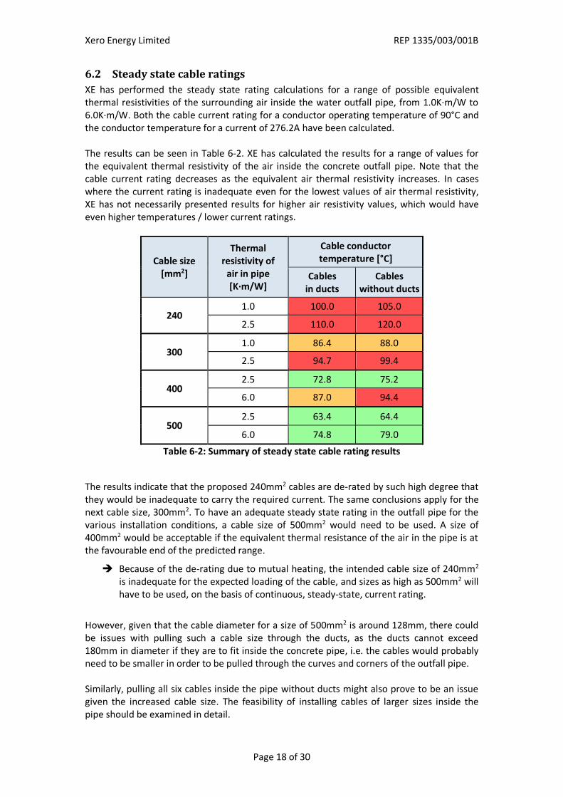
XE has performed the steady state rating calculations for a range of possible equivalent thermal resistivities of the surrounding air inside the water outfall pipe, from 1.0K∙m/W to 6.0K∙m/W. Both the cable current rating for a conductor operating temperature of 90°C and the conductor temperature for a current of 276.2A have been calculated. The results can be seen in Table 6-2. XE has calculated the results for a range of values for the equivalent thermal resistivity of the air inside the concrete outfall pipe. Note that the cable current rating decreases as the equivalent air thermal resistivity increases. In cases where the current rating is inadequate even for the lowest values of air thermal resistivity, XE has not necessarily presented results for higher air resistivity values, which would have even higher temperatures / lower current ratings.
Cable size [mm2]
Thermal resistivity of
air in pipe [K∙m/W]
Cable conductor temperature [°C]
Cables in ducts
Cables without ducts
240 1.0 100.0 105.0
2.5 110.0 120.0
300 1.0 86.4 88.0
2.5 94.7 99.4
400 2.5 72.8 75.2
6.0 87.0 94.4
500 2.5 63.4 64.4
6.0 74.8 79.0
Table 6-2: Summary of steady state cable rating results
The results indicate that the proposed 240mm2 cables are de-rated by such high degree that they would be inadequate to carry the required current. The same conclusions apply for the next cable size, 300mm2. To have an adequate steady state rating in the outfall pipe for the various installation conditions, a cable size of 500mm2 would need to be used. A size of 400mm2 would be acceptable if the equivalent thermal resistance of the air in the pipe is at the favourable end of the predicted range.
Because of the de-rating due to mutual heating, the intended cable size of 240mm2 is inadequate for the expected loading of the cable, and sizes as high as 500mm2 will have to be used, on the basis of continuous, steady-state, current rating.
However, given that the cable diameter for a size of 500mm2 is around 128mm, there could be issues with pulling such a cable size through the ducts, as the ducts cannot exceed 180mm in diameter if they are to fit inside the concrete pipe, i.e. the cables would probably need to be smaller in order to be pulled through the curves and corners of the outfall pipe. Similarly, pulling all six cables inside the pipe without ducts might also prove to be an issue given the increased cable size. The feasibility of installing cables of larger sizes inside the pipe should be examined in detail.
Xero Energy Limited REP 1335/003/001B
Page 19 of 30
6.3 Cyclic rating factors
The results of the cyclic rating factor calculations for the 240mm2 cable are shown below in Table 6-3.
Cable size [mm2]
Thermal resistivity of
air in pipe [K∙m/W]
Cyclic rating factor
Cables in ducts
Cables without ducts
240 1.0 1.24 1.27
3.0 1.29 1.30
Table 6-3: Cyclic rating factors for 240mm2 cable
The results for the 300mm2, 400mm2 and 500mm2 cables are similar and also in the range 1.24 - 1.30 and therefore are not presented in the table. The cyclic rating factor results are mostly affected by the shape of the daily cyclic variation in cable current. They are affected to a lesser degree by the cable installation arrangement and equivalent air thermal resistivity, and are affected very little by the cable conductor size. The calculated cyclic rating factors should be taken as indicative, because IEC6085 [4] applies to cables or cables in ducts in uniform soil and so does not take account of the air within the outfall pipe. However, as mentioned in Section 5.5, the ratio of peak power to RMS power, which is the same as the ratio of peak current to RMS current, is 1.31. This is a good first approximation for the steady state current that would provide the same cable heating as the cyclic current. The calculated cyclic rating factors, which also take into account the mutual heating between the cables, are slightly lower than this value and so appear to be reasonable.
Xero Energy Limited REP 1335/003/001B
Page 20 of 30
6.4 Cyclic cable ratings
To obtain cyclic cable ratings, the required steady state current of 276.2A has been divided by the least optimistic cyclic rating factor of 1.24, giving a current of 222.7A. This is the steady state current that will provide the same cable heating as a cyclically varying current that has a peak value of 276.2A and the shape shown in Figure 5-1. The steady state cable rating calculations have then been repeated using a current of 222.7A to represent the overall impact of the cyclic currents. The results are shown below in Table 6-4.
Cable size [mm2]
Thermal resistivity of
air in pipe [K∙m/W]
Cable conductor temperature [°C]
Cables in ducts
Cables without ducts
240
1.0 67.3 69.6
2.5 73.0 78.3
6.0 86.9 100.1
300 2.5 64.8 67.1
6.0 76.4 83.2
400 2.5 51.4 52.5
6.0 59.7 63.7
500 2.5 45.9 46.2
6.0 52.8 55.1
Table 6-4: Summary of cyclic cable rating results
Comparing the results in Table 6-4 and Table 6-2, the cyclic cable conductor temperatures are substantially lower. The cyclic results indicate that the 240mm2 cable is inadequate or marginal, while the 300mm2, 400mm2 and 500mm2 cables appear to have adequate ratings. However, care is needed in interpreting the results, given the uncertainty in modelling the air within the outfall pipe. It should also be noted that use of the cyclic ratings in reducing cable size from the continuous current case also reduces safety margins and a minimally sized cable based on cyclic ratings would have very little margin for error. This is discussed further in Section 7 below.
The cyclic cable rating calculations suggest that a cable size of 300mm2 or larger is required.
Xero Energy Limited REP 1335/003/001B
Page 21 of 30
7 General discussion
7.1 Uncertainty and assumptions
An important issue throughout the cable rating study is the uncertainty in the installation conditions and in the cable modelling assumed for the calculations since the thermal modelling is complex. Some of the key uncertainties are discussed below.
7.1.1 Material surrounding the concrete pipe
Lacking definitive data on the soil thermal resistivity, and based on the model selected for the calculations, where an “air bank” is surrounded by concrete, a typical value of 1K∙m/W has been assumed for the surrounding soil. However, the material surrounding the concrete pipe is expected to be a mix of rock ballast close to the landing point, and possibly chalk further along the way up the cliffs, with different and variable values of thermal resistivity. Cable rating is very sensitive to this variable, so even though the main issue is the enclosure of the cables within the concrete pipe, the surrounding soil at higher thermal resistivity values will have a negative effect on the cable ratings. XE suggests that this thermal rating study is revisited once samples of the ground soils along the pipe route have been obtained and actual values of the ground thermal resistivity established.
7.1.2 Concrete pipe burial depth
Another uncertainty concerns the burial depth of the cables and of the concrete pipe itself. Whilst close to the landing point there appears to be a minimum of 800mm of covering material from the top of the inside of the pipe to the ground surface, the exact depth will vary along the route of the pipe uphill. Lacking precise data on the outfall pipe profile and the ground elevation profile, XE has assumed an average burial depth of 1m, but notes that greater burial depths will have a negative impact on the cable ratings.
7.1.3 Current flow in the cables
XE has assumed that the current flowing through all six cables is the same, regardless of voltage. This assumes that each of the six cables will carry 5MW at 11kV, but this corresponds to 3MW for the 6.6kV cables (with an output below 30MW). In the absence of any data regarding the expected operational point of the tidal machines to be connected, or any requirements of the Distribution Network Operator, XE has calculated the current flow assuming a 0.95 power factor, which is not unusual. Operation closer to unity power factor will provide better ratings. It is also worth noting that ITP has advised that each berth could be developed up to 6MW (presumably at 11kV) and 3MW for 6.6kV, with cumulative export of six berths up to 30MW. Depending on how the berths are developed, it is possible that the cumulative current from PTEC could be greater than six times 276A (the assumption in this study). As current generates heat, this would result in worse thermal conditions. For example, a potential configuration of four 11kV cables at 6MW each and two 6.6kV cables at 3MW each (totalling 30MW) would lead to an average current of 313A per cable. This would exacerbate the thermal conditions in the outfall pipe which supports the case for larger cable sizes of 500mm2 or higher based on continuous current ratings.
Xero Energy Limited REP 1335/003/001B
Page 22 of 30
7.1.4 Convective air flows in the concrete pipe
Overall however, the largest area of uncertainty is the behaviour of the air in the concrete pipe. This is extremely difficult to model accurately as it provides heat transfer by convection, whereas solid materials provide heat transfer by conduction. In addition, the way in which this occurs is different along the pipe due to the varying installation conditions, one end being in water, open air vents, and changing angles of the pipe. Whilst XE has modelled this with a range of variables designed to capture this uncertainty it must be recognised that the convective effects will vary along the pipe and will be very difficult to understand and model with sufficient accuracy and confidence to provide a definitive cable rating. The model developed for cables in ducts is more certain than that for cables without ducts. This is because IEC60287 [3] takes account of the air within the ducts. Therefore the uncertainty for the case of cables in ducts is limited to the air between the ducts and the outfall pipe. For the case of cables without ducts, the uncertainty relates to convection of air within the relatively large space between the cables and outfall pipe. The case of cables in ducts, and the thermal resistivity of space inside the concrete outfall pipe is 1.0K∙m/W, can be interpreted as a situation where the spaces between the ducts and the outfall pipe are backfilled with a low thermal resistivity material such as bentonite. Filling cable ducts with bentonite is common practice for cables, but is probably not a practical proposition for PTEC. However, this case removes the uncertainties related to modelling the air within the outfall pipe and so the results in Table 6-3 and Table 6-4 for this case are reasonably accurate. The presence of air between the ducts and outfall pipe will provide a higher thermal resistance than bentonite. Therefore, if a particular cable is insufficiently rated for the case of cables in ducts and the equivalent thermal resistivity inside the concrete pipe is 1.0K∙m/W, it can be said with a high level of confidence that the cables are insufficiently rated for the application. Applying this criterion to the steady state results in Table 6-2, the 240mm2 and 300mm2 cables are not suitable for the application. However, applying this criterion to the cyclic results in Table 6-4 does not rule out any of the cable sizes. Judgment must therefore be applied to the cyclic results with respect to the uncertainty in modelling the air within the outfall pipe. In Table 6-4, the 240mm2 cable is marginal or insufficiently rated for an air thermal resistivity of 6.0K∙m/W. The larger cable sizes appear to be sufficiently rated for the case of equivalent air thermal resistivity of 6.0K∙m/W. The calculated cyclic operating temperatures are lower and the modelling uncertainties are less for the case of cables in ducts than for cables without ducts and so this installation method carries less risk. The larger cable sizes appear to be sufficiently rated for this installation method.
Xero Energy Limited REP 1335/003/001B
Page 23 of 30
7.2 Observations
XE has made several observations regarding the parameters and outcomes of the study, which should be carefully considered.
The rating of the proposed 240mm2 cables has been estimated by XE to be inadequate for the full steady state PTEC power output. XE has also examined larger cable sizes and established that a cable size of 500mm2 appears to be adequately rated. However, given the uncertainty over their installation method and the approximations used in the calculations, even this rating could be at risk.
The rating of the proposed 240mm2 cables has been estimated by XE to be marginal or inadequate based on cyclic ratings, i.e. the cyclic PTEC power output. Larger cable sizes of 300mm2, 400mm2 and 500mm2 appear to be adequately rated on this basis. However, given the uncertainty over their installation method and the approximations used in the calculations, these results cannot be taken as definitive and it would be prudent to select one of the larger cable sizes for safety.
The worst case scenario regarding the installation method appears to be with the cables laid directly in the pipe without individual ducts, as the proximity of the cables to each other increases their temperature and has a negative effect on the ratings. There will be little control over how the cables are arranged in this case and it is quite possible that hot spots will occur resulting in localised de-rating and risk of failures.
On the other hand, if the PTEC cables are laid in separate ducts, one in each, inside the concrete pipe, better ratings can be achieved with greater safety, giving more confidence to the ratings results over the uncertainties.
It should be noted however that there is a practical limit in the duct sizes that can allow six cables to easily fit into the pipe, and the duct size can also limit the cable size. XE notes that six ducts of outer diameter 180mm appears to be the absolute maximum that can be fit within the outfall pipe. This would probably have to be smaller to be able to fit around corners. Consequently, the larger cables such as 500mm2 may be much harder to pull through the ducts due to their larger diameter compared to the 240mm2 cables.
The PTEC cable dimensions have been approximated based on Nexans cable data in [5]. ITP has indicated that it wishes to use JDR cables (of which detailed data were not available), and should note that the cable dimensions and ratings may vary. However, no significant variations should be expected in the results.
The results are based on a burial depth of 1m for the concrete pipe, and on a relatively low thermal resistivity of 1.0K∙m/W for the material surrounding the pipe. If the burial depth at places is more than 1m, or the ground thermal resistivity is higher, this will have a negative effect on the cable ratings, and these assumptions should be verified along the whole route.
Xero Energy Limited REP 1335/003/001B
Page 24 of 30
7.3 Cable loading
XE has calculated the cable current ratings in Section 6 and the corresponding cable sizes based on full steady state output at nominal voltage of 11kV and a power factor of 0.95. The steady state rating calculations have also been performed for a constant loading, and therefore represent the worst operational case. This is in accordance with IEC standards and common practice. However, the actual cable loading at PTEC will be cyclic in nature, rather than continuous at full output. This effect has therefore also been assessed to understand what improvement in rating can be obtained. It is not presently common practice to select cable size based on cyclic rating, however since the proposed PTEC generators are tidal, their output is genuinely and predictably cyclic and so XE considers it reasonable to use cyclic ratings in this case. Given the overall uncertainty in the cable rating within the concrete outfall pipe, XE would suggest that safety margins and safety mechanisms, such as temperature sensing equipment, are built into the design. In this respect, XE considers it may be prudent to select a larger cable size than may appear absolutely necessary.
Xero Energy Limited REP 1335/003/001B
Page 25 of 30
8 Summary
8.1 General
XE has been commissioned by ITP to perform preliminary rating calculations for the export cables of PTEC. PTEC is planned for an output of 30MW, comprising six berths where tidal generators can connect. It is proposed to connect to a new onshore substation via six 11kV three-core 240mm2 armoured subsea cables from PTEC. The cables are proposed to be installed inside a concrete water outfall pipe at the proposed landing site. XE has examined two installation cases where the cables are either pulled directly into the concrete outfall pipe without individual ducts, or pulled through individual PE ducts, one for each cable within the concrete pipe. The aim of this study has been to determine the feasibility of such an installation in respect of cable sizes and ratings from a thermal perspective.
8.2 Assumptions
XE has examined two installation cases for the cables, one with and one without PE ducts. Since the two cases are not covered in the relevant cable rating standards, XE has created an equivalent model based on the standards to simulate the thermal effects of the air in the pipe surrounding the cables or ducts. A key aspect of XE’s modelling has been in establishing an equivalent thermal resistance of the air considering the complex convective air flows.
Figure 8-1: Examined installation cases (cables in ducts and cables without ducts)
XE has assumed a burial depth of 1m between the top of the concrete pipe and the ground surface, with a surrounding ground thermal resistivity of 1K·m/W and ground temperature of 15°C. For the ducts, XE has assumed flexible PE ducts at 180mm size to allow for both duct and cable installation. For the current flowing through the cables, XE has assumed that it will be the same for all cables, to simplify the rating calculations. XE has also assumed nominal voltage and a power factor of 0.95. Therefore, XE has assumed a maximum steady state current of 276.2A in each cable, corresponding to 5MW at 11kV (or to 3MW at 6.6kV). In addition to the steady state cable ratings, XE has calculated cyclic cable ratings for the same installation conditions. This uses a worst case daily current cycle developed from projected power output data provided by ITP [11].
Xero Energy Limited REP 1335/003/001B
Page 26 of 30
8.3 Cable rating results
XE has used the developed cable model to estimate the steady state and cyclic thermal ratings of the cables. The steady state ratings are presented as the conductor temperatures that result from the required current flow of 276.2A. In order to calculate cyclic cable ratings, a cyclic rating factor was first calculated, using the cable installation model and cyclic current model. The cyclic rating factor was then used to calculate the equivalent steady state current that will provide the same cable heating as the cyclically varying current with a peak value of 276.2A. The cyclic cable ratings were then calculated in the same way as the steady state cable ratings. XE has examined cable sizes of 240mm2 as proposed, 300mm2, 400mm2 and 500mm2. XE has performed the calculations for a range of equivalent thermal resistivities of the surrounding air inside the water outfall pipe from 1.0K∙m/W to 6.0K∙m/W. The steady state and cyclic rating results are presented in Table 8-1 below, with green indicating adequate rating, amber for marginal rating (temperatures above 85°C) and red indicating inadequate rating (temperatures exceeding 90°C).
Cable size
[mm2]
Thermal resistivity of
air in pipe [K∙m/W]
Cable conductor temperature [°C]
Steady state Cyclic
Cables in ducts
Cables without ducts
Cables in ducts
Cables without ducts
240
1.0 100.0 105.0 67.3 69.6
2.5 110.0 120.0 73.0 78.3
6.0 136.2 164.3 86.9 100.1
300
1.0 86.4 88.0 60.0 60.4
2.5 94.7 99.4 64.8 67.1
6.0 115.0 128.3 76.4 83.2
400 2.5 72.8 75.2 51.4 52.5
6.0 87.0 94.4 59.7 63.7
500 2.5 63.4 64.4 45.9 46.2
6.0 74.8 79.0 52.8 55.1
Table 8-1: Summary of steady state and cyclic cable rating results
The steady state results show that the proposed cable size of 240mm2 is inadequate for the expected steady state loading of the cable, and that a size of 500mm2 should be used. However, given that the cable diameter for this size is around 128mm, this might lead to issues with installation. The cyclic results show that the intended cable size of 240mm2 is marginal or inadequate for the expected cyclic loading of the cable. The larger cable sizes of 300mm2, 400mm2 and 500mm2 appear to be adequately rated for the expected cyclic loading.
Xero Energy Limited REP 1335/003/001B
Page 27 of 30
XE notes that there is significant uncertainty in modelling the air within the outfall pipe. The results for cables in ducts are more certain than for cables without ducts, because the model is more accurate for this case. Given the uncertainty of the conditions in the concrete outfall pipe, XE suggests that safety margins and safety mechanisms, such as temperature sensing equipment, are built into the design. XE also suggests that a larger cable size is preferred over the estimated minimum per the calculations.
Xero Energy Limited REP 1335/003/001B
Page 28 of 30
9 Recommendations XE recommends this study is revisited after the following items have been addressed in order to obtain more accurate results which will help pinpoint the optimum cable size and installation parameters:
The pipe profile and ground elevation profile should be determined, as this will allow more accurate calculations for the burial depth.
An assessment of ground conditions and thermal resistivity tests could be carried out over the length of the cable route (according to IEEE Std 442-1981 [12] or equivalent) as and if possible. The tests should ideally be performed to reflect the range of conditions over the course of a year.
Aside from the thermal issues in rating and sizing the cables, the practical aspects of installation should be addressed. This is particularly important in understanding whether the cables can actually be installed within the concrete outfall pipe safely and without damage and that they physically fit.
Should it be decided that the outfall pipe presents a feasible and preferred option for installation of the PTEC cables, XE recommends cable supplier specifications adequately address this and ITP ensures the cable supplier undertakes its own cable thermal (and mechanical) integrity analysis, design the cable accordingly and warrant it for installation and operation within the outfall pipe.
In addition to the above, ITP may wish to consider the following:
If the preferred installation method is to install the cables without ducts in the outfall pipe, other modelling approaches, such as those used for cable tunnels and for cables in multiple casings, should be investigated, and if reasonable to do so, studied and applied, to increase confidence in the results for this case.
A wider assessment of risks and issues with the cables installed in the concrete outfall pipe should be undertaken. This should cover the range of technical, engineering and practical issues but also cover operational aspects, decommissioning, environmental, health and safety, and commercial issues amongst others. XE considers that the proposals are very non-standard and will need a very thorough assessment across a broad range of aspects.
Xero Energy Limited REP 1335/003/001B
Page 29 of 30
10 References
[1] J. Hussey, “Cable drawings/spec”, email, 10 February 2014.
[2] JDR Cable Systems Ltd, “240 sqmm 11 kV subsea power cable”, Drawing number 103304A, 13 December 2013.
[3] International Electrotechnical Commission, “IS 60287 Electric cables- calculation of the current ratings”, 2001.
[4] International Electrotechnical Commission, “IS 60853 Calculation of the cyclic and emergency current rating of cables Part 1: Cyclic rating factor for cables up to and including 18/30 (36) kV”, 1985.
[5] Nexans, “Submarine Power Cables”, May 2008.
[6] IT Power Ltd, “PTEC Concept Single Line Diagram summary level”, PTEC-ITP-EL-SCH-018, 07 January 2014.
[7] J. Hussey, “FW: Flowers Brook Drawrings”, e-mail, 20 January 2014.
[8] Flowers Brook, “Pumping Station - S & E.O. plan and details”, JOWS/p/AB/3.20 issue Z, 2011.
[9] International Electrotechnical Commission, “IS 60228 - Conductors of insulated cables”, 2004.
[10] J. Hussey, “RE: 1335/002 PTEC offshore cable route study”, e-mail, 25 February 2014.
[11] J. Hussey, “PTEC annual 30MW output - best.xlsx”, 2014.
[12] The Institute of Electrical and Electronics Engineers, Inc, “IEEE Guide for Soil Thermal Resistivity”, IEEE Std 442-1981, 1981.
Xero Energy Limited REP 1335/003/001B
Page 30 of 30
11 Appendix A This appendix presents all the assumptions made by XE regarding the construction and the installation of the PTEC cables, taken from documentation provided by ITP, cable manufacturers [5] or common practice, as documented in XE’s internal knowledge. The assumptions are presented in the table below. Please note that this table is not exclusive, as it presents only the basic assumptions – the more detailed and technical assumptions made are stated throughout the report.
Item Assumption made Source / Notes
Cable
Cable construction Cross-linked Polyethylene (XLPE)
Cable manufacturer [5]
Conductor max. temperature
90°C Cable manufacturer [5]
Cable sizes (single core)
240mm2 Cu Conductor 300mm2 Cu Conductor 400mm2 Cu Conductor 500mm2 Cu Conductor
As requested by ITP and larger sizes
Screen bond Fully bonded (both ends) Cable manufacturer [5]