Repair Manual EA6100P EA6101P Caution: Before doing any maintenance or service work, the combination switch must be in STOP position (ignition current interrupted), in order to prevent unintended starting by the easy start system!
Transcript
Repair Manual
EA6100PEA6101P
Caution:Before doing any maintenance or service work, the combination switch must be in STOP position (ignition current
interrupted), in order to prevent unintended starting by the easy start system!
Repair Manual EA6100P / EA6101P 2
INHALT
TECHNICAL DATA ...................................................................................... 3
00 SPECIAL TOOLS ......................................................................................... 4
01 CHAIN TENSIONING SYSTEM ................................................................... 6 Chain tensioner / Function / Assembly ..................................................... 6
02 CLUTCH DRUM / CHAIN SPROCKET ....................................................... 7 Sprocket and clutch drum with needle bearing ........................................ 7
03 CHAIN BRAKE / GUIDE BAR BOLT .......................................................... 8 Removing the brake band ........................................................................ 8 Remove the handguard and disengagement mechanism ........................ 8 Replacing the guide bar bolt ..................................................................... 9
04 CLUTCH ..................................................................................................... 10 Disassembly ........................................................................................... 10 Inserting the yweights ............................................................................11 Installing the clutch ..................................................................................11
05 OIL PUMP .................................................................................................. 12 General ................................................................................................... 12 Disassembly ........................................................................................... 12 Removing the oil pump ........................................................................... 12 Removing the oil tank vent ..................................................................... 12
10 TANK .......................................................................................................... 23 Grip mechanism ..................................................................................... 23
Removing the tank ................................................................................. 24 Pressure test .......................................................................................... 24 Vacuum testing ventilation valve ............................................................ 24 Parts ....................................................................................................... 24
11 CYLINDER / PISTON ................................................................................. 25 Drive, pressure test ................................................................................. 25 Drive, vacuum test .................................................................................. 25 Cylinder and piston disassembly ............................................................ 26 Assembling the cylinder and piston ........................................................ 26
EA6100P EA6101PStroke volume cm3 61Bore mm 47Stroke mm 35Max. power at rated speed kW / 1/min 3.4 / 10,000Max. torque at speed Nm / 1/min 3.7 / 7,000Idling speed / max. engine speed with bar and chain 1/min 2,700 / 13,800Clutch engagement speed 1/min 5,100Sound pressure level at the workplace LpA, eq per ISO 22868 1) 3) dB(A) 105 / KpA = 2.5Sound power level LWA, Fl + Ra per ISO 22868 2) 3) dB(A) 117 / KWA = 2.5Vibration acceleration ahv, eq per ISO 22867 1) 3)
- Tubular handle m/s2 5.0 / K = 2- Rear handle m/s2 4.0 / K = 2
Carburetor Type Diaphragm carburetorIgnition system Type electronicSpark plug Type NGK BPMR 7Aor spark plug Type -Electrode gap mm 0.5Fuel consumption at max. load per ISO 7293 kg/h 1.5Speci c consumption at max. load per ISO 7293 g/kWh 430Fuel tank capacity l 0.8Chain oil tank capacity l 0.48Mixture ratio (fuel/two-stroke oil)
- when using MAKITA oil 50 : 1 / 100: 1 (EXTRA)- when using Aspen Alkylat (two-stroke fuel) 50 : 1 (2%)- when using other oils 50 : 1 (quality grade: JASO FC or ISO EGD)
Chain brake engages manually or in case of kickbackChain speed (at max. engine speed) m/s .325=25.6 3/8=29.6Sprocket pitch inch .325 oder 3/8Number of teeth Z 7Chain type see the Extract from the spare-parts listPitch / gauge inch / (mm) .325 / 0.058 (1.5 mm) oder 3/8 / 0.058 (1.5 mm)Guide bar, length of a cut cm 38 / 45 / 53Guide-bar type see the Extract from the spare-parts listWeight (fuel tank empty, without chain, guide bar and accessories) kg 6.0 6.1
1) Figures derived in equal part from idling, full-load and racing speed.2) Figures derived in equal part from full-load and racing speed.3) Uncertainty (K=).
Repair Manual EA6100P / EA6101P 4
1 Torx screwdriver Grip 944.500.860 T-grip 200 mm 944.500.862 T-grip 100 mm 944.500.861
2 Mandrel Disassembly mandrel for tapping out the
ywheel without damage to the crankshaft thread 944.500.880
3 Setting gauge Gauge for measuring the gap
between ywheel and armature 944.500.891
4 Torque wrench 3/8�” Drive socket 944.500.864 Bit 152 mm 944.500.865 Bit 49 mm 944.500.866 Torque wrench 3/8�” Drive 950.230.000
5 Piston stop wedge Wedge for blocking the engine
through the exhaust port 944.602.000
6 Assembly and disassembly wrench Wrench for disassembling and
assembling the centrifugal clutch 944.500.590
7 Tachometer Electronic tachometer for measuring
the engine speed of2- and 4-stroke engines 950.233.220
00 SPECIAL TOOLS
Repair Manual EA6100P / EA6101P 5
00 SPECIAL TOOLS
8 Disassembly hook Removal/installation Brake band spring 950.237.000
9 Needle-nose pliers Various assembly/ disassembly tasks 944.603.400
10 Over/underpressure pump For checking sealing of radial rings/carburetor 957.004.001
11 Sealing plate For sealing intake side 944.603.200
12 Sealing plate For sealing exhaust side 944.603.180
13 Ignition tester Checking the ignition 950.233.230
14 Radial ring puller 15 mm radial ring puller 944.500.895 Spindle 950.203.020
Repair Manual EA6100P / EA6101P 6
1
23
01 CHAIN TENSIONING SYSTEM
Remove the sprocket guard, bar, and chain.
CAUTION: Do not work on the chain brake unless the spring is detensioned!
Chain tensionerUnscrew 4 screws, and remove the cover.
Chain tensioner functionAn angled worm drive converts the turns of the adjustment screw 1 to forward or backward motion of the tensioning pin 2.
If necessary, turn adjusting screw 1 clockwise, until the fastening screw 3 is accessible.Unscrew the fastening screw and pull the chain tensioner up and out.
AssemblyNOTE: The worm gear is available only as a set.
Grease spindle and worm gear with multi-purpose grease (944.360.000).Lock the cover bolts with Loctite 601.
Repair Manual EA6100P / EA6101P 7
5
4
3 2
1
02 CLUTCH DRUM / CHAIN SPROCKET
Remove the sprocket guard, bar, and chain.Release the chain brake.Remove the circlip 5 with the universal wrench.Remove cup washer.
Sprocket and clutch drum with needle bearingCheck the chain sprocket 4 for damage and wear.Important customer information:Before installing a new saw chain, always check the condition of the chain sprocket. A worn chain sprocket will damage a new saw chain, and must be replaced.Check the clutch drum needle bearing for wear and damage.Assembly the bearing with multi-purpose high-performance grease (944.360.000).
Check the inside and outside of the clutch drum 3 for damage and wear.Replace the clutch drum if annealing.Note: Make sure to assemble with thrust washer 1!Note: Always use a new circlip 5 (927.408.000)!When assembling the clutch drum, make sure that the lug of the oil pump drive 2 is not positioned on the oil pump drive. When inserting, turn the clutch drum slightly.
Repair Manual EA6100P / EA6101P 8
Removing the brake bandCAUTION: To prevent cuts, wear protective gloves and disassembly the spike bar (2 screws)!Remove the sprocket guard, bar, and chain.Pull the handguard towards the tubular handle to release the chain brake.Remove the clutch drum, see chapter 02.Push the hand guard forward to engage the chain brake. This releases the brake band spring.Remove the cover plate, see chapter 01.Fold the brake band 1 upward and turn it out of the disengagement mechanism 2.
Secure the chain saw from slipping (vise).Using the disassembly hook (chap. 00, Pos. 8), disengage the brake band spring 3.
Remove the handguard and disengagement mechanismUnscrew bolt 4 and pull out the sleeve 5.
1 2 3
4
5
03 CHAIN BRAKE / GUIDE BAR BOLT
Repair Manual EA6100P / EA6101P 9
Remove the circlip 6.Pull the disengagement mechanism up in parallel with the axes.Pull off the handguard with gentle back-and-forth motion.Note: When reassembling always use a new circlip 6 (927.304.000)!
Note: Make sure that the handguard guide 7 is not unhooked. If necessary, push it back into position with a screwdriver (about 5 mm from the axle support). The handguard can only be assembled when the rest piece is in this position.Assemble the handguard and disengagement mechanism, brake band and brake band spring in reverse order.
03 CHAIN BRAKE / GUIDE BAR BOLT
67
ca. 5 mm
Replacing the guide bar boltScrew two nuts onto the bar bolt and counterlock them.Unscrew the bar bolt.Assembly: Apply Loctite 243 (980.009.000) to the guide bar bolts and turn them all the way in.
Repair Manual EA6100P / EA6101P 10
DisassemblyCAUTION: To prevent cuts, wear protective gloves and disassembly the spike bar (2 screws)!Remove the sprocket guard, bar and chain.Pull the handguard towards the front handle to release the chain brake if necessary.Remove the clutch drum, see chapter 02.Remove the muf er. To do this, unscrew the 3 screws 1 and remove the muf er 2.
Caution: If a catalytic converter is being used, the muf er will be very hot after operation!
Move piston to bottom dead centre (visible through the exhaust opening).Press the piston stop wedge 3 (cap. 00, pos. 5) into the exhaust opening.
Position of gasket and cooling plate for muf er assembly:
Insert wrench 4 (chap. 00, Pos. 6) into the clutch and use a socket wrench 5 to turn in the direction of the arrow (left-hand thread) to loosen and remove the clutch.Remove the guide washer (inside of the clutch).The yweights can now be pushed off the guide axially in one direction.
04 CLUTCH
1
2 3
4 5
Repair Manual EA6100P / EA6101P 11
Inserting the yweightsHook the springs as shown in the illustration.Then press the yweights onto the guide. To do this, rst push on two yweights half-way, then put on the third yweight by setting it on its edge.Press the yweights all the way onto the guide.CAUTION: Note the position of the springs. Do not replace springs individually! If a spring breaks or is fatigued, all three springs must be replaced. The springs must not touch the cover.The illustration shows the inside of the clutch.
Installing the clutchInstall the clutch with the arrow marking point up.Mounting torque: 35 +/-2.5 Nm
CAUTION: Before installing the clutch, disassemble the starter (chap. 06) in order to prevent damage to the starting catches.
Press the disc onto the clutch. It must be at and be engaged.
04 CLUTCH
Repair Manual EA6100P / EA6101P 12
1
2
35
6
A
A
8
7
GeneralThe oil pump is driven by the clutch drum. Lugs on the clutch drum transfer the power to the drive arms of the oil pump drive 1.The drive worm of the oil pump drive engages in the teeth of the oil pump 3.This means that oil is pumped only when the chain is running.The oil ow rate can be adjusted with adjusting screw A:�• Turn right for more oil�• Turn left for less oil
DisassemblyRemove the clutch drum and clutch, see chapter 04. Remove brake band, see chapter 03.Turn the oil pump drive 1 counter-clockwise and pull it off the shaft.
Pull the oil pressure line 2 from the oil pump.Unsrew screw 4 and remove the oil pump.Remove spacer ring 5 from the crankshaft.
Note: Make sure to install in the right position. See illustration.
The suction line 6 remains in the crankcase. It extends into the oil tank. To remove it, carefully pull on the connection to the oil pump.Removing the oil pumpPush the adjusting screw A up against the spring pressure and turn it until the pin 7 goes into the assembly slit 7. If necessary press the supply piston 8 in somewhat.Note: When assembling put the adjusting screw A counterclockwise to stop.Removing the oil tank ventNote: The ventilation valve 9 must be punched into the tank.Press in a new valve about 2 mm deep under the housing surface.Make sure that the ventilation channel 10 is free of deposits. Clean if necessary.
05 OIL PUMP
1
234A
910
Repair Manual EA6100P / EA6101P 13
DisassemblyDisengage the hood clip 3 with the combina-tion tool.Unscrew four screws 1 and remove the fan housing 2.Remove the air guide 5 from the fan housing.CAREFUL! Injury hazard! Do not unscrew screw 10 if the return spring is under ten-sion.Unscrew screw 10 and remove the driver 9 with spring 8 and the cable drum 7.Separate the driver 9 and cable drum 7.Lightly tap the fan housing on a wooden sur-face with the entire surface of the hollow side, and hold it down. Now lift the fan housing carefully and in small steps. This will allow the return spring pack 6, which should now have fallen out, to relax in a controlled man-ner if the return spring has popped out of the plastic pack.
06 STARTER
1
3
2
109
8
7
6
5
11
4
CAREFUL! Injury hazard! The return spring can pop out! Always wear eye protection and protective gloves!If the spring pops out, put it back into the plastic housing as shown in the schematic.
Assembly
Note: If installing a new return spring cassette, grease it on the spring side.Carefully insert a new return spring cassette 6 and press down until it engages. Lightly grease the surface of the spring and spring cassette with multipurpose grease (944.360.000).Insert spring 8 in the cable drum 7 and thread in a new cable (dia. 3.8 mm, 1 m long) as shown. Tie knots in both ends and tighten. Press the knot on the cable drum into the space provided.Guide the hole 11 in the driver over the end of the spring, press down the driver and turn it slightly counter-clockwise until it is ush on the cable drum 7.Put the drum 7 on its spindle and turn it slightly until the return spring engages.Insert screw 10 and tighten.Tension the return spring clockwise. Turn the return spring about 6 turns with the aid of the cable, which should be pressed into the gap in the cable drum.Place the air guide 5 in the fan housing and make sure the ve recesses 4 engage.Position the fan housing correctly on the saw, press against it slightly, and pull the starter handle until the starter catches.Tighten screws 1.
Repair Manual EA6100P / EA6101P 14
07 IGNITION SYSTEM (TROUBLE-SHOOTING)
yes
Is the spark plug dry and properly installed?
Is the spark gap correct? (should be 0.5 mm)
Is the spark plug oily or does it have carbon deposits on it?
Is there damage to the insulation of the high-voltage cable or the ignition cable, or to the wires themselves?
Is the gap between the flywheel and the ignition module outside of the 0.25-0.3 mm range?
Remove flywheel and check. Is the flywheel damaged?Is the positioning key damaged?
Continue with troubleshooting in fuel system (tank, fuel hose, carburetor).
Remove spark plug. Is the spark plug damaged? Is it the wrong kind of spark plug? Is there carbon on the electrodes?
no
yes
no
yes
no
no
no
no
no
no
yes
yes
Dry spark plug cap and fasten firmly to spark plug. If needed, replace the cap or cap spring.
Replace spark plug. Use ONLY a spark plug approved by MAKITA.See operating manual! Otherwise the ignition module might be damaged.
Eliminate the causes for carbon deposits on electrodes (bad two-stroke oil, wrong mix,defective air filter, check carburetor adjustment).
Use MAKITA EXTRA two-stroke oil.
Adjust spark gap.
Wash spark plug in acetone. Do not sandblast! If necessary, replace spark plug.
Eliminate cause: wrong carburetor setting, too much oil in fuel, frequent short operations.
Replace spark plug and check ignition module for corrosion, if necessary replace. Has the defect been remedied?
Replace high-voltage cable and/or ignition cable. Has the defect been remedied?
Check radial play of drive shaft, and repair if needed.Replace ignition module if traces of overheating become visible.
Adjust gap between flywheel and ignition module correctly.
Replace flywheel or key. Before installation wipe cone seat at drive shaftand flywheel with acetone or alcohol to remove any grease.
Tighten fastening nut to the correct torque! Has the defect been remedied?
Replace ignition module. Has the defect been remedied?
no
Install ignition testing lamp.
Alternatively, using insulated pliers, hold the unscrewed spark plugagainst the cylinder.
Caution: Do not hold the spark plug directly against the hole. Detonation hazard!
Pull the starting cable smartly. Is there an ignition spark?
Is the gap uneven? Has the flywheel worn against the ignition module?
no
no
yes
yes
yes
no
no
Repair Manual EA6100P / EA6101P 15
Spark plugDisengage the hood clips 1 with the combina-tion tool and remove the hood 2.
CAUTION:Do not touch the spark plug or plug cap if the engine is running (high voltage).Switch off the engine before starting any maintenance work.A hot engine can cause burns. Wear protective gloves!
The spark plug (NGK BPMR 7A, parts no. 965 603 021) must be replaced in case of damage to the insulator, electrode erosion (burn) or if the electrodes are very dirty or oily.Pull the plug cap 3 off the spark plug. Use only the combination wrench supplied with the saw to remove the spark plug.The electrode gap must be 0.5 mm.
23 1
07 IGNITION SYSTEM
Normal
Proper spark plug,good combustion
Deposits
Poor-quality oil,material wear
Overheating
Wrong thermal value
Carbon deposits
Wrong spark plugWrong thermal value
Repair Manual EA6100P / EA6101P 16
1
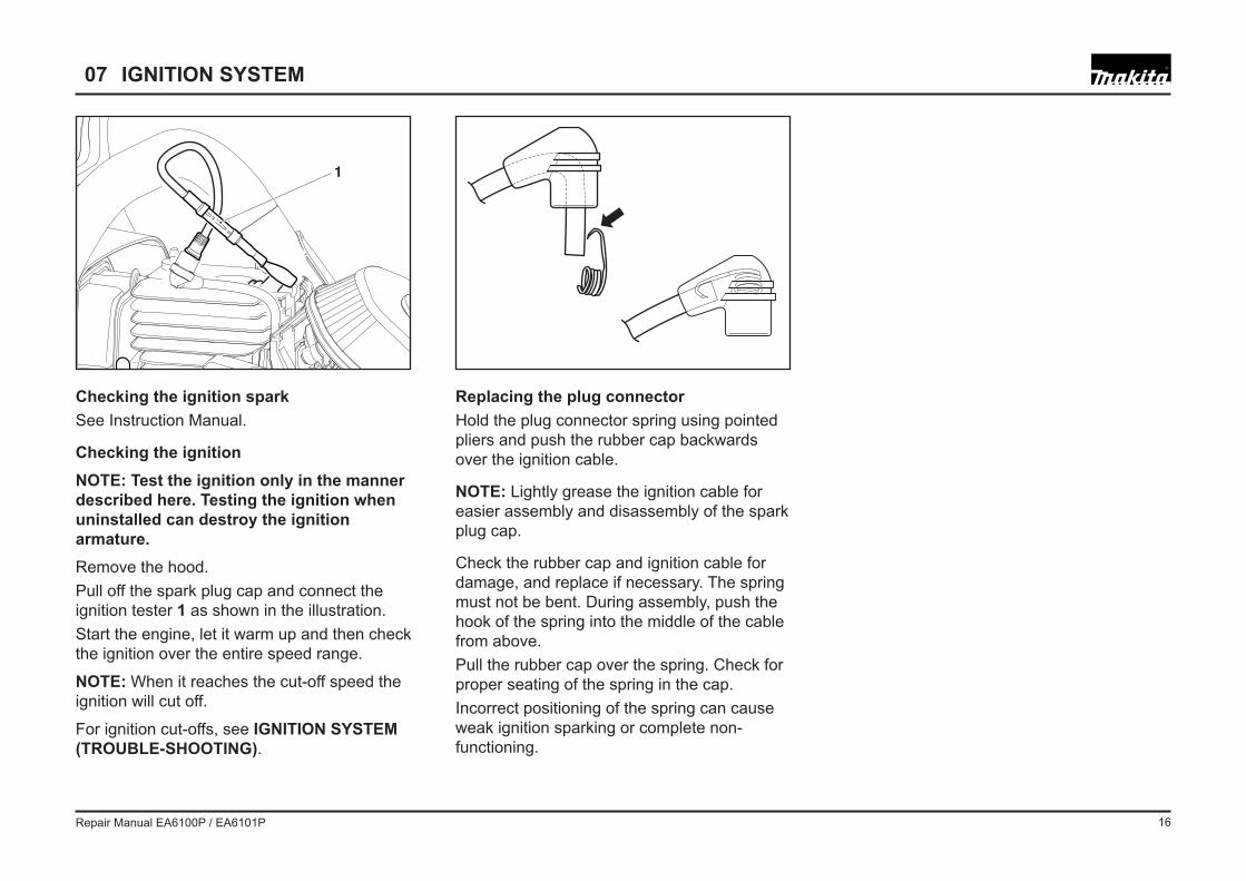
Checking the ignition sparkSee Instruction Manual.
Checking the ignitionNOTE: Test the ignition only in the manner described here. Testing the ignition when uninstalled can destroy the ignition armature.Remove the hood.Pull off the spark plug cap and connect the ignition tester 1 as shown in the illustration.Start the engine, let it warm up and then check the ignition over the entire speed range.
NOTE: When it reaches the cut-off speed the ignition will cut off.
For ignition cut-offs, see IGNITION SYSTEM (TROUBLE-SHOOTING).
Replacing the plug connectorHold the plug connector spring using pointed pliers and push the rubber cap backwards over the ignition cable.
NOTE: Lightly grease the ignition cable for easier assembly and disassembly of the spark plug cap.
Check the rubber cap and ignition cable for damage, and replace if necessary. The spring must not be bent. During assembly, push the hook of the spring into the middle of the cable from above.Pull the rubber cap over the spring. Check for proper seating of the spring in the cap.Incorrect positioning of the spring can cause weak ignition sparking or complete non-functioning.
07 IGNITION SYSTEM
Repair Manual EA6100P / EA6101P 17
Removing the ywheelRemove the starting system, see chapter 06.Block the piston, see chapter 04.Loosen the nut in the direction of the arrow and remove it along with the washer.
Screw the disassembly mandrel (chap. 00, Pos. 2) onto the threaded end of the shaft.Do not screw the mandrel all the way down. Leave about 2 mm between the mandrel and the ywheel.Hold the machine in one hand and knock the ywheel loose with a tap on the mandrel.CAUTION: The cone of the crankshaft must always be degreased before assembly.Nut tightening torque: 28 +/-2.0 Nm
07 IGNITION SYSTEM
Starting ratchetsCheck the starter pawls on the ywheel for easy movement, and clean if necessary.Install spring as illustrated. Screw tightening torque: 8 +/-1.0 Nm.
Repair Manual EA6100P / EA6101P 18
Removing the ignition armatureRemove the cover.Remove the starter. See Chap. 06.Remove the ywheel. See Chap. 07.Unscrew 2 bolts on ignition armature 1.Pull off cable lug 2 .Unscrew bolt 3 and remove with cooling air guide.Unscrew bolt 4 and remove with cable clamp.Remove ignition armature with high-voltage cable, carefully pulling cable lug 2 through the rubber grommet on the carburettor oor.
Installing the ignition armatureNOTE: The high-voltage cable is moulded onto the ignition system and cannot be replaced separately.Insert the ignition armature and screw in the screws until just before they stop.
Secure the high-voltage cable under the cable clamp with bolt 4.Carefully push cable lug 2 through the rubber grommet on the carburettor oor.
Note: Make sure not to press the rubber grommet into the carburettor when doing this. If the grommet gets pushed out, it can be reinserted from the cylinder side.
Route the high-voltage cable as shown, engage the cooling air guide tab 5 and secure it with bolt 3.Install the ywheel.Insert the setting gauge 6 (chap. 00, Pos. 3) between the ignition armature and the fylwheel.Position the ywheel so that the magnet is against the armature (gap 0.25 �– 0.3 mm).
Press the armature against the gauge towards the ywheel and tighten the armature screws (5 +/-0.5 Nm). Then check the gap again to make sure it is correct.
Combination switch
Remove the cover and air lter. Pull off cable lug 2.Unscrew 4 anged nuts 8 (A/F 7).Unscrew bolts 7.Carefully remove the air lter base from the rubber buffers 9 and disengage the choke linkage (arrow).The combination switch 10 with ground wire and contact spring can now be removed from the air lter base.
Note: If the gasket on the carburetor or air ap is damaged, it must be replaced.
Assemble in reverse order.
07 IGNITION SYSTEM
1
43
2
5
6
7
8
910
Repair Manual EA6100P / EA6101P 19
6 7
23
41
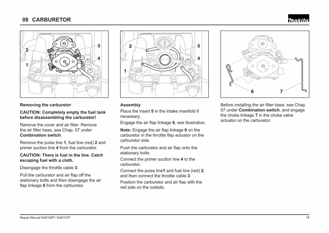
Removing the carburetorCAUTION: Completely empty the fuel tank before disassembling the carburetor!Remove the cover and air lter. Remove the air lter base, see Chap. 07 under Combination switch.
Remove the pulse line 1, fuel line (red) 2 and primer suction line 4 from the carburetor.
CAUTION: There is fuel in the line. Catch escaping fuel with a cloth.Disengage the throttle cable 3.
Pull the carburetor and air ap off the stationary bolts and then disengage the air ap linkage 6 from the carburetor.
AssemblyPlace the insert 5 in the intake manifold if necessary.Engage the air ap linkage 6, see illustration.
Note: Engage the air ap linkage 6 on the carburetor in the throttle ap actuator on the carburetor side.
Push the carburetor and air ap onto the stationary bolts.Connect the primer suction line 4 to the carburetor.Connect the pulse line1 and fuel line (red) 2, and then connect the throttle cable 3.Position the carburetor and air ap with the red side on the outside.
Before installing the air lter base, see Chap. 07 under Combination switch, and engage the choke linkage 7 in the choke valve actuator on the carburetor.
08 CARBURETOR
2 5
4
1
Repair Manual EA6100P / EA6101P 20
14 15
16 17
1
212
13
11
08 CARBURETOR
Removing the carburetor base Remove the insert 5 from the intake manifold if necessary.Detach the Bowden cable 11.Remove the carburetor ange 10 from the intake manifolds.Remove the primer return line 12 from the primer.Unscrew 3 bolts 8.Lift the carburetor base slightly and pull the rubber grommet 9 with the short-circuit cable down and off.Carefully remove the carburetor base while letting the Bowden cable 11 and lines slide out of the base.
AssemblyAssemble in reverse order.Route the lines as shown.Tighten bolts 8 to 5 +/-0.5 Nm.
Removing the manifold angeUnscrew 4 bolts 13 and remove the manifold ange.
1 Pulse line
2 Fuel line (red)
4 Primer suction line (top primer connection)
12 Primer return line (bottom primer connection)
Note: Check all lines for cracks and damage. Any damaged lines must be replaced.
115
12
8
9
10
Intake diaphragm (reed valve)
If the intake diaphragm 16 is damaged or protruding away from the air hose ange, it must be replaced.
Note: Turn the side with TOP on it to the outside when assembling.
Tighten screw 17 to 3 +/-0.5 Nm.
Note: After pushing the carburetor manifold 14 through the ange, put in the insert 15.Tighten bolts 13 to 5 +/- 0.5 Nm.
Repair Manual EA6100P / EA6101P 21
08 CARBURETOR
Pressure test
Connect the pressure gauge (956.004.001) to the carburetor fuel connection 23.Set up a pressure of max. 0.5 bar.If the pressure drops off, check the inlet needle 24 for damage or foreign objects. If necessary, replace control parts.If the inlet needle is OK, replace the gasket 20 and diaphragm 21.
If the pump diaphragm 18 is obviously dented, it needs to be replaced along with the gasket 19.Check:�• Screen 22 for contamination�• Pulse hole for contamination
Check control parts(control lever/inlet needle):Check the tip of the inlet needle for wear.Check control lever for correct installation, see illustration to the bottom.
If the control lever is too low:�• Insuf cient fuel�• Poor acceleration�• No max. speed
If the control lever is too high:�• Carburetor ooding�• Warm starting problems�• Poor idling
19
18
20
21
24
2223
T
HL
Control leverCorrectly installed
Control leverToo low
Control leverToo high
Base SettingH= 2 1/2L= 1 1/2
Control lever
Repair Manual EA6100P / EA6101P 22
09 VIBRATION DAMPER
Damper spring ARemove the cover for easier disassembly.Unscrew bolt 1 from damper spring A.
Damper spring B and CRemove the sprocket guard, bar, and chain.Remove starter housing (see chap. 06).Unscrew bolts 2 from damper springs A, B and C.
NOTE: The engine unit is connected to the tank unit by fuel lines and the throttle cable. The two units cannot be separated!
Carefully lift the engine unit on the clutch side over damper springs B and C (spread the engine unit slightly apart from the tank).
Unscrew the damper springs.
Damper spring DNote: Damper spring D cannot be removed until damper springs A, B and C have been removed.Carefully lift the engine unit on the fan side over damper spring D and spread the engine unit slightly apart from the tank. Unscrew the damper springs.Assemble in reverse order.
Make sure the fuel lines remain connected to the tank.
1
2
A
B
C
D2
DisassemblyCAUTION: To prevent cuts, wear protective gloves and disassembly the spike bar (2 screws)!
Note: For removal and installation, guide the Torx screwdriver through damper springs.
Repair Manual EA6100P / EA6101P 23
10 TANK
Grip mechanismThe throttle trigger is linked to the carburetor by a Bowden cable.NOTE: Do not lubricate the Bowden cable!The grip shell is attached to the tank with a Torx screw 3.Disengage the throttle lock 1 and spring 2.Check for ease of motion and functioning of the safety throttle lock spring 2.To replace the throttle trigger and throttle lockon lever drive out the cylinder pins 5 (3.3 x 28.4 mm) with a mandrel (ø 2 mm).
3
1
4
5
2
Repair Manual EA6100P / EA6101P 24
Removing the tankNOTE: Make sure the fuel tank is empty before removing it.Remove the ywheel. See Chap. 09. Detach the throttle cable from the carburetor, see Chap. 08. Detach the Bowden cable from the carburetor ange, see Chap. 08. Spread the engine unit and the tank unit apart a little and use needle-nose pliers to carefully pull the fuel lines off the fuel nipple. Separate the tank and the engine unit.Note: When attaching the lines, connect the
fuel line (red) to the fuel nipple 7.Pressure testAttach the over/underpressure pump (chap. 00 pos. 11) to one of the two fuel connection. (6 or 7). Seal off the second connection.Set up a pressure of max. 0.3 bar.If the pressure drops off, check the following:
Air valve�• Fuel line�• Tank cap O-ring�• Check tank for holes�•
Note: Detergent can be used to localise leaks.
Vacuum testing ventilation valve 9Attach the over/underpressure pump as described.When the pump is operated the underpressure must quickly dissipate.If underpressure builds, replace the ventilation valve.Pull out the ventilation valve 9 with a small screwdriver or wire. Before inserting a new valve, wet it with fuel.
PartsTo remove the suction head 8 pull it through the tank opening with a hooked wire.Note: Do not use pliers, as this may damage the line. Do not pull on the suction head or fuel line, because they can otherwise be drawn into the inside of the tank.
Turn the fuel nipple slightly counter-clockwise out of the retainer and then carefully lift it out with a sharp at point screwdriver.
Note: Do not lever against the line connections, as this can break them off.
10 TANK
7
6
98
Repair Manual EA6100P / EA6101P 25
11 CYLINDER / PISTON
1
2
Drive, pressure testIf it is not possible to adjust the carburetor properly, it will be necessary to check the sealing of the Drive.
To seal the exhaust side, install sealing plate 1 (944.603.180) in the place of the muf er (rubber coating towards the cylinder). To do this it will be necessary to remove the muf er, see chap. 04.
To seal the intake side, install sealing plate 2 (944.603.200) in the place of the carburetor unit. To do this it will be necessary to remove the carburetor unit, see chap. 07 and 08.Connect the over/underpressure pump to the connection on the sealing plate 2 (944.603.200)
Move the piston to top dead centre.Pull the pulse line from the cylinder connection and seal the connection.Set up a pressure of max. 0.5 bar.If the pressure drops within 20 seconds, it can have one of these causes:�• Radial ring leaking�• Cylinder base gasket leaking�• Crankcase gasket leaking�• Crack in crankcase�• Crack in cylinder�• Spark plug leakingNOTE: Detergent can be used to localise leaks. If there is a leak into the oil tank, it will not be possible to fully identify the leak. If pressure remains steady in the crankcase after shutting off the oil line hole, for example with a rubber stopper (see chap. 05), it is
an indication that there is a defect in the crankcase gasket to the oil tank.Drive, vacuum testSince the radial gasket ring can also fail at negative pressure, a vacuum must be established in the crankcase to test the radial ring.Seal off the intake and exhaust sides as described above.Connect the over/underpressure pump to the connection on the sealing plate 2.Move the piston to top dead centre.Pull the pulse line from the cylinder connection and seal the connection.Set up a negative pressure of max. 0.5 bar.If the pressure does not rise to more than 0.3 bar within 20 seconds, the radial gasket is OK. Otherwise the radial gaskets must be replaced.Remove the ywheel and clutch, see IGNITION SYSTEM and CLUTCH / CLUTCH DRUM.On the clutch side, pull the circlip from the shaft.Guide the 15 mm radial gasket puller (944.500.895) over the shaft and turn it rmly into the radial gasket. When the spindle is screwed in, it will press against the shaft and pull the radial gasket out.Caution: Under no circumstances hammer in the puller.
Repair Manual EA6100P / EA6101P 26
11 CYLINDER / PISTON
Cylinder and piston disassembly Remove the muf er, see chap. 04. Remove the starting system, see chap. 06. Remove the carburetor unit, see chapter 08.Unscrew the cylinder bolts and pull the cylinder up and off.Remove and reinstall the circlip 5 with needle-nose pliers.
Assembling the cylinder and pistonCarefully remove any gasket residues!Use a new cylinder base gasket 2!Before assembly, lightly oil the cylinder race, piston and needle bearing 6!Install the piston with the arrow marking 4 on the outlet side of the camshaft (piston ring lock on the inlet side).Move piston to bottom dead centre.Position the opening on the piston ring towards the piston ring lock.Use the piston ring tensioner 1 to press the piston ring together.Push the cylinder onto the piston. Let the piston ring tensioner slide down with it.Remove the piston ring tensioner and press the cylinder all the way down on the pins 3.Hand-tighten the screws lightly crosswise, and then tighten to the correct torque (12 +1.0 Nm), again crosswise.
1
3
4
5
6
2
Repair Manual EA6100P / EA6101P 27
DisassemblyTo disassemble, unscrew the 6 bolts. Using a rubber hammer, carefully drive the crankshaft out of the crankcase MS.
Remove spacer ring 2 from the crankshaft. Using a rubber hammer, carefully drive the crankshaft out of the crankcase CS.
To remove and install the bearings, heat the crankcase CS and MS to 160-180°C.
AssemblingNOTE: Before installation, apply �“Loctite 620�” to the outer ring of the bearing.
Place the bearings in the hot crankcase.When driving the crankshaft into the crankcase MS or CS, support the crankshaft side between the webs.
When installing the second crankcase half, the crankshaft webs must be supported against each other.
NOTE: Make sure to remove the support after assembly.Before assembly, carefully clean all sealing surfaces and remove any remnants of the old gasket. When assembling, install a new gasket.Hand-tighten the screws lightly crosswise, and then tighten to the correct torque (12 +1.0 Nm), again crosswise.After bolting the crankcase sides together, cut off the ash 1.
The complete crankcase is divided into:�• CS crankcase clutch side�• MS crankcase magneto sideTwo pins ensure tting.
1
2KS
MS
12 CRANKCASE
CS
Repair Manual EA6100P / EA6101P 28
Screw Part No. Size Qty. Torque [Nm]crank case MS with CS 908.405.255 Torx 6 10 +/-1cylinder on crank case 908.005.255 Torx 4 12 +/-1reed valve to air hose 908.004.085 Torx 1 3 +/-0,5air hose to cylinder 908.405.145 Torx 4 5 +/-0,5carburetor base on crank case 908.005.165 Torx 4 5 +/-0,5muf er to cylinder 908.005.205 Torx 2 8 +/-1muf er to cylinder, upper screw 908.305.405 Torx 1 8 +/-1contact spring to intake manifold 915.135.100 cross recess 1 1,5 +/-0,2air lter base to intake manifold 175.131.300 A/F 7 4 3 +/-0,5oil pump to crank case 908.005.165 Torx 1 5 +/-0,5clutch on crankshaft --- M12 x 1 L 1 35 +/-2,5chain tensioner gear cover to crankcase 908.705.125 Torx 1 5 +/-0,5bar bolt to bar ange 195.232.010 M8 SK6/M8 (Lock with Loctite 243) 2 15 +/-1assembly of sprocket guard 923.208.004 A/F 13 2 1 +/-0,5brake cover 908.105.124 Torx 4 5 +/-0,5ignition coil cpl. crank case 908.805.205 Torx 2 5 +/-0,5 ywheel fastening by nut 920.308.024 A/F 13 1 28 +/-2,0starter cpl. to crank case 908.005.205 Torx 3 5 +/-0,5handguard mounting to starter housing 908.005.205 Torx 1 5 +/-0,5grip half / rear handguard to tank 913.455.164 Torx 1 5 +/-0,5fastening of tubular handle at side of tank 913.455.204 Torx 1 5 +/-0,5fastening of tubular handle on bottom of tank 913.455.204 Torx 2 5 +/-0,5side support cover to tank 913.455.204 Torx 1 5 +/-0,5side support cover to damping spring 908.006.145 Torx 1 5 +/-0,5damping spring - tank magnet side back 181.114.300 Torx 1 5 +/-0,5damping spring - tank clutch side front 181.114.300 Torx 1 5 +/-0,5damping spring - tank clutch side back 130.114.400 Torx 1 5 +/-0,5damping spring - cylinder 181.114.400 Torx 1 5 +/-0,5crank case MS/damping 908.006.145 Torx 1 5 +/-0,5crank case CS/damping 908.006.145 Torx 2 5 +/-0,5spike bar to crank case 908.005.165 Torx 2 5+/-0,5spark plug 965.603.021 A/F 19 1 15 +/-5starting ratchets to ywheel 170.166.041 Torx 2 8 +/-1ignition cable holder 908.005.095 Torx 1 5 +/-0,5evacuation tube 908.005.095 Torx 1 5 +/-0,5air lter --- M4 1 3+/-0,5