+ All Categories
Home > Documents > REPAIR PARTS CATALOG FOR SUNNEN …REPAIR PARTS CATALOG FOR SUNNEN® HORIZONTAL HONES & ACCESSORIES...

REPAIR PARTS CATALOG FOR SUNNEN …REPAIR PARTS CATALOG FOR SUNNEN® HORIZONTAL HONES & ACCESSORIES...

Date post: 13-Apr-2020
Category:
Upload: others
View: 36 times
Download: 0 times
Share this document with a friend
28
REPAIR PARTS CATALOG FOR SUNNEN ® HORIZONTAL HONES & ACCESSORIES MODEL: CH-100IK & CHV-901 X-CH-1110 SUNNEN ® PRODUCTS COMPANY 7910 MANCHESTER AVENUE • ST. LOUIS, MO 63143, U.S.A. • PHONE: 314-781-2100 “SUNNEN AND THE SUNNEN LOGO ARE REGISTERED TRADEMARKS OF SUNNEN PRODUCTS COMPANY.”
Transcript

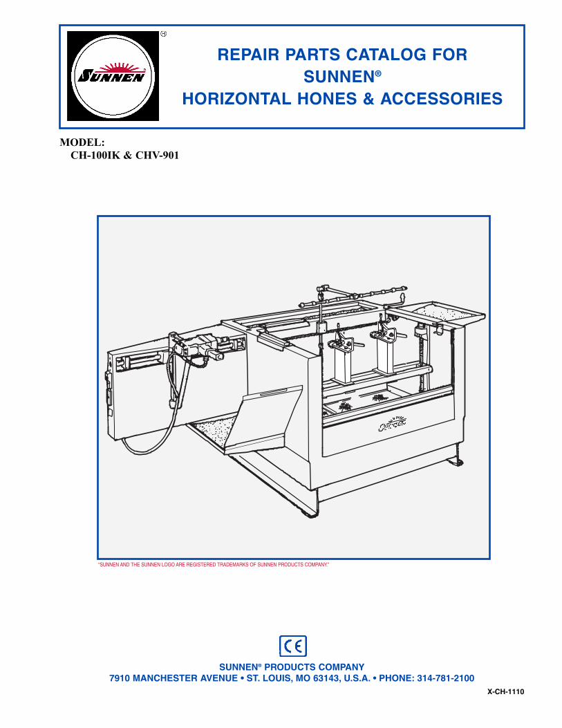
REPAIR PARTS CATALOG FORSUNNEN®

HORIZONTAL HONES & ACCESSORIES

MODEL:

CH-100IK & CHV-901

X-CH-1110

SUNNEN® PRODUCTS COMPANY7910 MANCHESTER AVENUE • ST. LOUIS, MO 63143, U.S.A. • PHONE: 314-781-2100

“SUNNEN AND THE SUNNEN LOGO ARE REGISTERED TRADEMARKS OF SUNNEN PRODUCTS COMPANY.”

Like any machinery, this equipment maybe dangerous if used improperly. Be sureto read and follow instructions foroperation of equipment.

iii

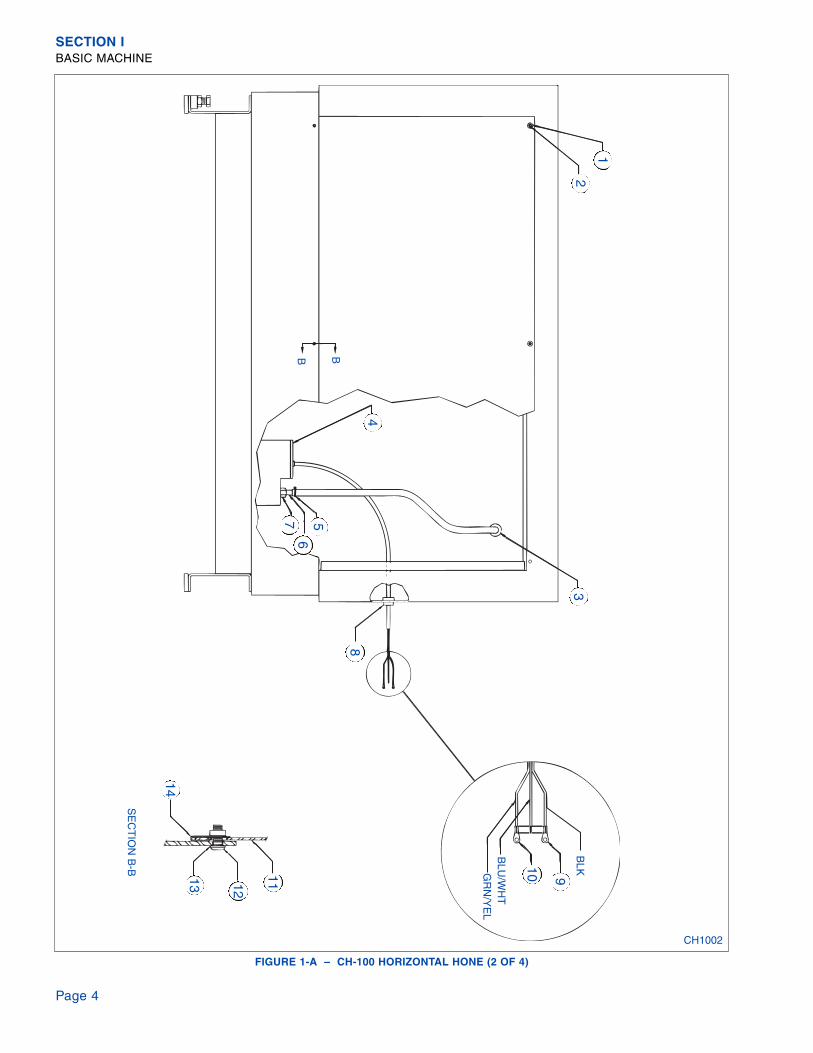
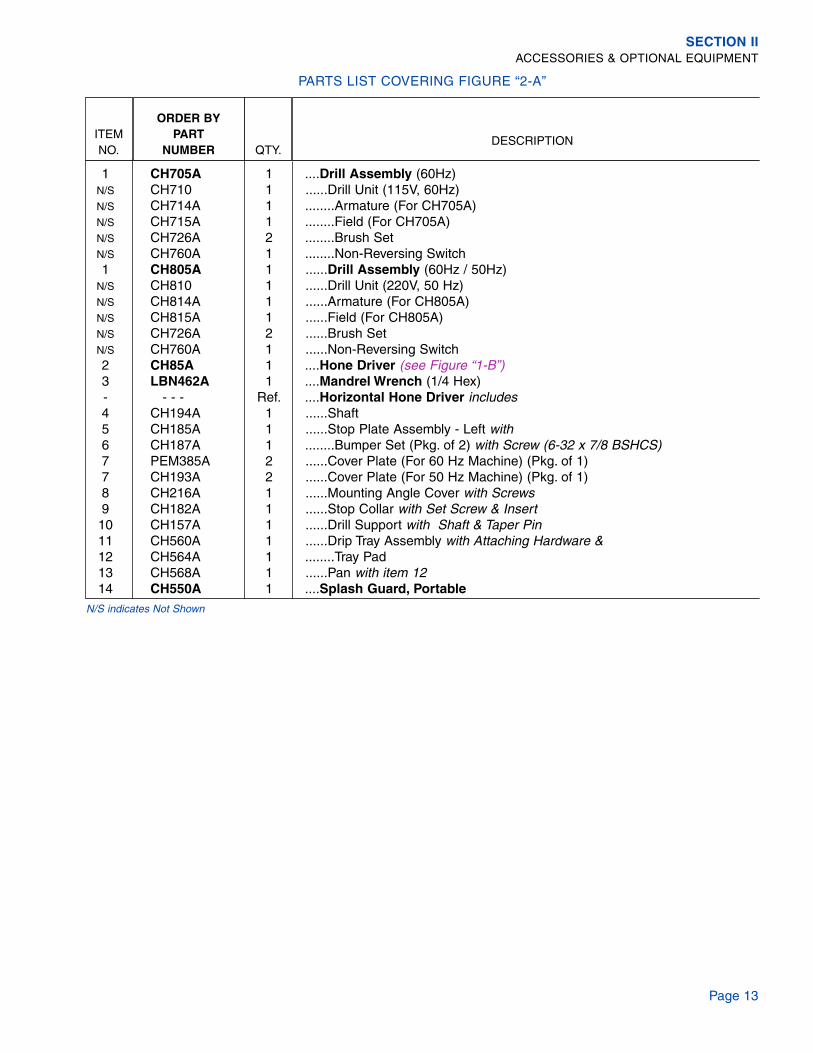
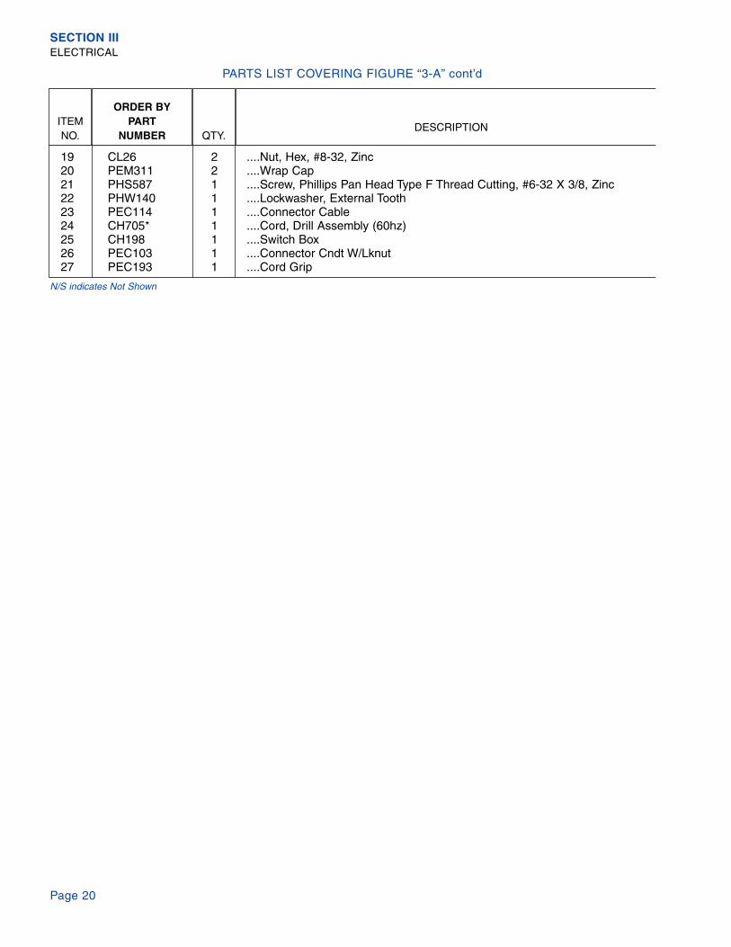
INTRODUCTIONIllustrations show all major components in exploded detail. Item numbers on each illustration are keyed to thecorresponding parts list, providing a descriptive identification of each part.

The parts lists include assemblies as well as detail parts. An item listed without a part number can beobtained as a component of the complete assembly of which it is a part.

Standard hardware items are listed with complete descriptions, such as Item 29 below. These may bepurchased at your local hardware store, but it is important to replace an item with one having the samedimensions as the original. In some places brand names and part numbers are shown. These may changedepending upon availability.

Sunnen Products Company reserves the right to make changes, without notice, to materials,specifications, colors, designs and accessories included with units.

HOW TO ORDERWhen ordering replacement parts be sure to include the following information to ensure prompt shipment ofcorrect parts:

1. The part number and description of each part desired, obtained from this parts catalog.

2. The quantity of each part desired.

3. The voltage, frequency and phase, when ordering electrical parts.

4. The model and serial number of the machine, obtained from the name plate, where there is any questionconcerning a part.

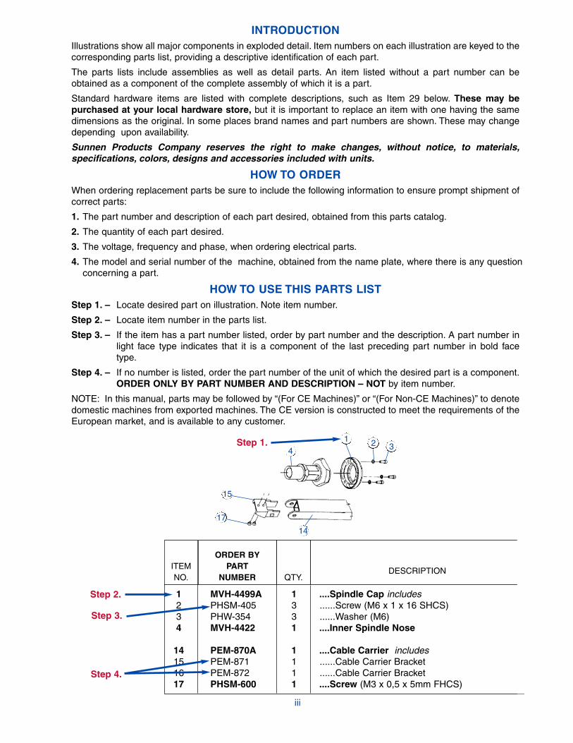
HOW TO USE THIS PARTS LISTStep 1. – Locate desired part on illustration. Note item number.

Step 2. – Locate item number in the parts list.

Step 3. – If the item has a part number listed, order by part number and the description. A part number in light face type indicates that it is a component of the last preceding part number in bold face type.

Step 4. – If no number is listed, order the part number of the unit of which the desired part is a component.ORDER ONLY BY PART NUMBER AND DESCRIPTION – NOT by item number.

NOTE: In this manual, parts may be followed by “(For CE Machines)” or “(For Non-CE Machines)” to denotedomestic machines from exported machines. The CE version is constructed to meet the requirements of theEuropean market, and is available to any customer.

ITEMNO.

ORDER BYPART

NUMBER QTY.DESCRIPTION

1 MVH-4499A 1 ....Spindle Cap includes2 PHSM-405 3 ......Screw (M6 x 1 x 16 SHCS)3 PHW-354 3 ......Washer (M6)4 MVH-4422 1 ....Inner Spindle Nose

14 PEM-870A 1 ....Cable Carrier includes15 PEM-871 1 ......Cable Carrier Bracket16 PEM-872 1 ......Cable Carrier Bracket17 PHSM-600 1 ....Screw (M3 x 0,5 x 5mm FHCS)

Step 1.

Step 2.

Step 3.

Step 4.

17

41 2 3

15

14

GENERAL INFORMATION

The Sunnen® equipment has been designed and engineered for a wide variety of parts within the capacity and limitation of the equipment. With proper careand maintenance this equipment will give years of service.

READ THE FOLLOWING INSTRUCTIONS CAREFULLY AND THOROUGHLY BEFORE UNPACKING, INSPECTING, OR INSTALLING THIS EQUIPMENT.

IMPORTANT: Read any supplemental instructions BEFORE installing this equipment. These supplemental instructions give you important information toassist you with the planning and installation of your Sunnen equipment.

Sunnen Technical Service Department is available to provide telephone assistance for installation, programming, & troubleshooting of your Sunnenequipment. All support is available during normal business hours, 8:00 AM to 4:30 PM Central Time. Emergency breakdown support is available on a 24hour / 7 day basis.

Review all literature provided with your Sunnen equipment. This literature provides valuable information for proper installation, operation, and maintenanceof your equipment. Troubleshooting information can also be found within the Instructions. If you cannot find what you need, call for technical support.

Where applicable, programming information for your Sunnen equipment is also included. Most answers can be found in the literature packaged with yourequipment.

Help us help you. When ordering parts, requesting information, or technical assistance about your equipment, please have the followinginformation available:

• Have ALL MANUALS on hand. The Customer Services Representative or Technician will refer to it.• Have Model Number and Serial Number printed on your equipment Specification Nameplate.• Where Applicable: Have Drive model and all nameplate data. Motor type, brand, and all nameplate data.

For Troubleshooting, additional information may be required:• Power distribution information (type - delta, wye, power factor correction; other major switching devices used, voltage fluctuations)• Installation Wiring (separation of power & control wire; wire type/class used, distance between drive and motor, grounding).• Use of any optional devices/equipment between the Drive & motor (output chokes, etc.).

For fast service on your orders call:Sunnen Automotive Customer Service toll free at: 1-800-772-2878Sunnen Industrial Customer Service toll free at: 1-800-325-3670Customers outside the USA, contact your local authorized Sunnen Distributor.Additional information available at: http://www.sunnen.com or e-mail: [email protected]

NOTE: Sunnen reserves the right to change or revise specifications and product design in connection with any feature of our products contained herein.Such changes do not entitle the buyer to corresponding changes, improvements, additions, or replacements for equipment, supplies or accessoriespreviously sold. Information contained herein is considered to be accurate based on available information at the time of printing. Should any discrepancy ofinformation arise, Sunnen recommends that user verify the discrepancy with Sunnen before proceeding.

ESD PREVENTION REVIEW

Let's review the basics of a sound static control system and its effective implementation. First, in the three step plan:

1. Always ground yourself when handling sensitive components or assemblies.

2. Always use a conductive or shielded container during storage or transportation. These materials create a Faradaycage which will isolate the contents from static charges.

3. Open ESD safe containers only at a static safe work station.

At the static safe work station, follow these procedures before beginning any work:

A. Put on your wrist strap or foot grounding devices.

B. Check all grounding cords to make sure they are properly connected to ground, ensuring the effective dissipation of sta-tic charges.

C. Make sure that your work surface is clean and clear of unnecessary materials, particularly common plastics.

D. Anti-static bubble wrap has been included for use at the machine when an ESD safe workstation is not available.

You are now properly grounded and ready to begin work. Following these few simple rules and using a little common sense will go a longway toward helping you and your company in the battle against the hazards of static electricity. When you are working with ESD sensi-tive devices, make sure you:

GROUND

ISOLATE

NEUTRALIZE

iv

SUNNEN® LIMITED PRODUCT WARRANTY

Sunnen® Products Company and its subsidiaries (SPC) warrant that all new SPC honing machines, gaging equipment, tooling, and related equipment willbe free of defects in material and/or workmanship for a period of one year from the date of original shipment from SPC.

Upon prompt notification of a defect during the one-year period, SPC will repair, replace, or refund the purchase price, with respect to parts that prove to bedefective (as defined above). Any equipment or tooling which is found to be defective from improper use will be returned at the customer's cost or repaired(if possible) at customer's request. Customer shall be charged current rates for all such repair.

Prior to returning any SPC product, an authorization (RMA#) and shipping instructions must be obtained from the Customer Service Department or itemssent to SPC will be returned to the customer.

Warranty Limitations and Exclusions This Warranty does not apply to the following:

• Normal maintenance items subject to wear and tear: (belts, fuses, filters, etc).

• Damages resulting from but not limited to:› Shipment to the customer (for items delivered to customer or customer's agent F.O.B., Shipping Point)› Incorrect installation including improper lifting, dropping and/or placement› Incorrect electric power (beyond +/- 10% of rated voltage) including intermittent or random voltage spikes or drops› Incorrect air supply volume and/or pressure and/or contaminated air supply› Electromagnetic or radio frequency interference from surrounding equipment (EMI, RFI)› Storm, lightning, flood or fire damage› Failure to perform regular maintenance as outlined in SPC manuals› Improper machine setup or operation causing a crash to occur› Misapplication of the equipment› Use of non-SPC machines, tooling, abrasive, fixturing, coolant, repair parts, or filtration› Incorrect software installation and/or misuse› Non-authorized customer installed electronics and/or software› Customer modifications to SPC software

THE LIMITED WARRANTY DESCRIBED HEREIN IS EXPRESSLY IN LIEU OF ALL ANY OTHER WARRANTIES. SPC MAKES NO REPRESENTATION OR WARRANTY OF ANYOTHER KIND, EXPRESS OR IMPLIED, WHETHER AS TO MERCHANTABILITY, FITNESS FOR A PARTICULAR PURPOSE OR ANY OTHER MATTER. SPC IS NOTRESPONSIBLE FOR THE IMPROPER USE OF ANY OF ITS PRODUCTS. SPC SHALL NOT BE LIABLE FOR DIRECT, INDIRECT, INCIDENTAL, OR CONSEQUENTIALDAMAGES INCLUDING BUT NOT LIMITED TO: LOSS OF USE, REVENUE, OR PROFIT. SPC ASSUMES NO LIABILITY FOR PURCHASED ITEMS PRODUCED BY OTHERMANUFACTURERS WHO EXTEND SEPARATE WARRANTIES. REGARDLESS OF ANY RIGHTS AFFORDED BY LAW TO BUYER, SPC's LIABILITY, IF ANY, FOR ANY ANDALL CLAIMS FOR LOSS OR DAMAGES WITH RESPECT TO THE PRODUCTS, AND BUYER'S SOLE AND EXCLUSIVE REMEDY THEREFORE, SHALL IN ALL EVENTS BELIMITED IN AMOUNT TO THE PURCHASE PRICE OF THAT PORTION OF THE PRODUCTS WITH RESPECT TO WHICH A VALID CLAIM IS MADE.

Shipping DamagesExcept in the case of F.O.B., Buyer's destination shipments, SPC will not be liable for any settlement claims for obvious and/or concealed shipping damages.The customer bears the responsibility to unpack all shipments immediately and inspect for damage. When obvious and/or concealed damage is found, thecustomer must immediately notify the carrier's agent to make an inspection and file a claim. The customer should retain the shipping container and packingmaterial.

SUNNEN® SOFTWARE LICENSE AGREEMENT

This document is a Legal Agreement between you, as user and licensee (Licensee), and Sunnen® Products Company (SPC) with respect to preprogrammedsoftware (Software) provided by SPC for use on SPC Equipment. By using the Software, you, as Licensee, agree to become bound by the terms of thisAgreement.

In consideration of payment of the license fee (License Fee) which is part of the price evidenced by your receipt (Receipt), SPC grants to you as Licenseea non-exclusive right, without right to sub-license, to use the particular copy of the SPC Software licensed hereunder only on the particular equipment sold withthe Software. SPC reserves all rights including rights not otherwise expressly granted, and retain title and ownership to the Software including all subsequentcopies or updates in any media. The Software and all accompanying written materials are covered by copyrights owned by SPC. If supplied on removablemedia (floppy disk), you, as Licensee, may copy the Software only for back up purposes; or you may request that SPC copy the Software for you for thesame purposes. All other copying of the Software or of the accompanying written materials is expressly forbidden and is in violation of the Agreement.

The Software and accompanying written materials (including the user's manual, if any) are provided in an "as is" condition without warranty of any kindincluding the implied warranties of merchantability and fitness for a particular purpose, even if SPC has been advised of this purpose. SPC specifically doesnot warrant that it will be liable as a result of the operation of the Software for any direct, indirect, consequential or accidental damages arising out of theuse of or inability to use such product even if SPC has been advised of the possibility of such use. It is recognized that some states do not allow the exclu-sion or limitation of liability for consequential or accidental damages and to the extent this is true, the above limitations may not apply.

Any alteration or reverse engineering of the software is expressly forbidden and is in violation of this agreement.

SPC reserves the right to update the software covered by this agreement at any time without prior notice and any such updates are covered by thisagreement.

v

vi

SAFETY INSTRUCTIONSREAD FIRST

This machine, like any equipment, may be dangerous if used improperly. Pleaseread all warnings and instructions before attempting to use this machine.

Always disconnect power at main enclosure before servicing machine.1

Always wear eye protection when operating this machine.

NEVER open or remove any machine cover or protective guard with power "ON."Always disconnect power at main enclosure before servicing this equipment.1

DO NOT attempt any repair or maintenance procedure beyond those described inthis book. Contact your Sunnen® Field Service Engineer or Technical ServicesRepresentative for repairs not covered in these instructions.

Due to the wide variety of machine configurations, all possibilities cannot bedescribed in these instructions. Instructions for safe use and maintenance ofoptional equipment ordered through Sunnen, will be provided through separatedocumentation and/or training provided by your Sunnen Field Service Engineer orTechnical Services Representative.

DO NOT attempt to defeat any safety device on this machine or on any of theoptional equipment.

If specially built automation components are added to this system, be sure thatsafety is not compromised. If necessary, obtain special enlarged work area safetysystem from Sunnen Products Co.

Indicates CE version ONLY.

1 DO NOT touch electrical components until main input power has been turned off and CHARGElamps are extinguished. WARNING: The capacitors are still charged and can be quite dangerous.

Page 1

CONTENTS

Introduction .......................................................................................................... iiiHow To Order ....................................................................................................... iiiHow To Use This Parts List ................................................................................. iiiGeneral Information ............................................................................................. ivESD Prevention Review ....................................................................................... ivLimited Product Warranty .................................................................................... vSunnen Software License Agreement .................................................................. vGeneral Safety Instructions .................................................................................. viContents ............................................................................................................... 1

SECTION I - BASIC MACHINE1-A CH100IK Horizontal Hone .................................................................................... 21-B Hone Driver........................................................................................................... 10

SECTION II - ACCESSORIES & OPTIONAL EQUIPMENT2-A CH20A/40A Horizontal Hone Driver ..................................................................... 122-B CH455 Cradle & CH525 Oil Control Assemblies.................................................. 142-C CHV901 Universal Honing Fixture........................................................................ 16

SECTION III - ELECTRICAL3-A CH850K Control Panel Assembly......................................................................... 18

PAGE

“SUNNEN AND THE SUNNEN LOGO ARE REGISTERED TRADEMARKS OF SUNNEN PRODUCTS COMPANY.”

© Copyright 2011 by Sunnen® Products Company • Printed in U.S.A.

Page 2

SECTION I - BASIC MACHINE

FIGURE 1-A – CH-100 HORIZONTAL HONE (1 OF 4)

CH1001

2

34

5

1

678

9

10

1112

13

1416

17

15

1918

20

21

22

23

24

2526

2728

29

3132

36

37

38

3940

3334

3542

43

4445

46

AA

SE

CT

ION

A-A

DE

TAIL O

F C

HA

INC

ON

NE

CT

ING

LINK

INS

IDE

VIE

W - R

IGH

T S

IDE

INS

IDE

VIE

W - LE

FT

SID

E

30

41

Page 3

SECTION IBASIC MACHINE

ITEMNO.

ORDER BYPART

NUMBER QTY.DESCRIPTION

1 CH458 2 ....Chain2 CH470 1 ....Tee Handle Assembly3 KN538 1 ....Flatwasher4 CH469 1 ....Clamp Plate5 CH498 2 ....Cross Bar6 PHS528 4 ....Screw (3/8-16 X 2-1/2 HHCS)7 LBN407 4 ....Flatwasher (.375 Id X .875 Od X .065 Thk)8 CH465 1 ....Elevating Nut Assembly, Left9 KN386 6 ....Nut, Hex (1/2-13)10 CH464 2 ....Idler Adjustment Screw11 CH468SC 1 ....Elevating Nut Rt. Side12 CK1128 1 ....Stop Collar Upper13 PHS104 1 ....Setscrew (3/8-16 X 1/2 SHSS)14 PBR42 2 ....Bearing Thrust15 CH435 2 ....Bearing Support Block16 PHS654 4 ....Screw (3/8-16 X 2-3/4 SHCS)17 CH420 2 ....Elevating Screw Assembly18 PNP331 1 ....Label, Safety Glass (CE)19 PNP407 1 ....Label, Warning (CE)20 CH462 1 ....Chain21 CH540 1 ....Valve Body Assembly22 CH510 1 ....Oil Spout Assembly23 PEM302 1 ....Locknut24 CHV199 1 ....Elevating Handle25 CH440 2 ....Idler Arm Assembly26 CH568 1 ....Pan27 CH454 2 ....Adjusting Cam28 KN370 4 ....Flatwasher (.515 Id X .875 Od X .050 Thk)29 PHS665 2 ....Screw (1/2-13 X 3-1/2 HHCS)30 CH705 1 ....Drill Assembly (60Hz) (see Figure “2-A”)30 CH805 1 ....Drill Assembly (60Hz / 50Hz) (see Figure “2-A”)31 PHS523 1 ....Screw (3/4-16 X 2-1/2 HHCS)32 PHN109 1 ....Nut, Hex Jam, 3/4-16, Black Oxide33 PPP345 2 ....Reducer Coupling34 PPP193 2 ....Hose Barb35 PEM305 2 ....Wire Hose Clamp36 CV6040 1 ....Front Door - Upper Section37 CH497 2 ....Clamp Nut38 CV6023 1 ....Front Door - Lower Section39 CH320 1 ....Base40 CH352 1 ....Coolant Hose41 CH901 1 ....Universal Honing Fixture (see Figure “2-C”)42 CH4581 3 ....Connecting Pin43 CH4582 3 ....Cotter Pin44 CH541 1 ....Clamp Plate45 CH542 1 ....Spacer46 PHS559 3 ....Screw (5/16-18 X 1-3/4 SHCS)N/S CH65 1 ....Accessory Kit

PARTS LIST COVERING FIGURE “1-A” (1 of 4)

(Parts continued on next page)N/S indicates Not Shown

Page 4

SECTION IBASIC MACHINE

FIGURE 1-A – CH-100 HORIZONTAL HONE (2 OF 4)

CH1002

1

23

4

56

7

8

9

101112

13

14

BLK

BLU

/WH

TG

RN

/YE

L

B

SE

CT

ION

B-B

B

Page 5

SECTION IBASIC MACHINE

ITEMNO.

ORDER BYPART

NUMBER QTY.DESCRIPTION

1 LBA451 1 ....Lockwasher, External Tooth (#10)2 PHS506 3 ....Screw (#10-32 X 3/8 BSHCS)3 PHM771 1 ....Grommet4 HS205 1 ....Pump (110/115V)4 HS210 1 ....Pump (220/230V)5 PEM305 1 ....Wire Hose Clamp6 PPP193 1 ....Hose Barb7 PPP194 1 ....Reducer Coupling8 PHM771 1 ....Grommet9 PET713 1 ....Terminal10 PET712 1 ....Terminal11 CH416 1 ....Back Panel12 PHS611 3 ....Screw (1/4-20 X 5/8 BSHCS)13 PHW118 3 ....Lockwasher, 1/4, Zinc14 PHN120 3 ....J-Nut (1/4-20)

PARTS LIST COVERING FIGURE “1-A” (2 of 4)

(Parts continued on next page)N/S indicates Not Shown

Page 6

SECTION IBASIC MACHINE

FIGURE 1-A – CH-100 HORIZONTAL HONE (3 OF 4)

CH1003

1

2

34

5678

910

11

1417 16

13

1819

20

21

23 22

15 12

2425

2930

35

37

36

34

31

32

33

26

2728

SE

CT

ION

C-C

EN

D V

IEW

C C

38

Page 7

SECTION IBASIC MACHINE

ITEMNO.

ORDER BYPART

NUMBER QTY.DESCRIPTION

1 CH116 1 ....Mounting Angle Assembly2 PHN134 2 ....Nut, Keps (#10-32)3 PHS614 2 ....Screw (#10-32 X 1/2 BSHCS)4 PEM341 2 ....Clamp5 EC105 1 ....Electrical Conduit6 MAN1028 6 ....Screw (1/4-20 X 3/4 HHCS)7 LBN431 5 ....Nut, Hex (1/4-20)8 LBN401 8 ....Flatwasher (.266 Id X .630 Od X .065 Thk)9 PHS611 1 ....Screw (1/4-20 X 5/8 BSHCS) 10 PEM336 1 ....Clamp11 CH129 1 ....Shaft Support12 LN0113 1 ....Setscrew (5/16-18 X 7/16 DPSHSS)13 CH190 1 ....Stop Plate Assembly, Right14 CH135 1 ....Carriage & Torque Arm15 CH185 1 ....Stop Plate Assembly, Left16 PNP345 1 ....Label, Arrow17 CH164 1 ....Spacer Plate18 CH166 1 ....Spacer Plate19 PHS973 4 ....Screw20 PHW118 4 ....Lockwasher (1/4)21 CH85 1 ....Quick Coupler Assembly22 PNP299 2 ....Electrical Decal23 CH705 1 ....Drill Assembly (60Hz) (see Figure “2-A”)23 CH805 1 ....Drill Assembly (60Hz / 50Hz) (see Figure “2-A”)24 PHS511 2 ....Screw (#10-24 X 3/8 BSHCS)25 PEM341 2 ....Clamp26 CH194 1 ....Shaft27a LBA451 4 ....Lockwasher, External Tooth (#10)27b PHS506 4 ....Screw (#10-32 X 3/8 BSHCS)28 CH216G 1 ....Mounting Angle Cover29 MAN1223 2 ....Lockwasher, 3/8, Plain30 PHS651 2 ....Screw (3/8-16 X 7/8 BSHCS)31 POR106 4 ....O-Ring (1/8" ID X 1/16")32 PEM301 1 ....Locknut33 PEM279 1 ....Nipple Chase34 CH208 1 ....Cover Plate35 PHS666 2 ....Screw (#6-32 X 3/4 PPHMS)36 KN231 4 ....Drivescrew (#0 X 3/16 RHDS)37 PNP103 1 ....Nameplate (Serialized)38 CH850 Ref. ....Control Panel Assembly (see Figure “3-A”)

PARTS LIST COVERING FIGURE “1-A” (3 of 4)

(Parts continued on next page)N/S indicates Not Shown

Page 8

SECTION IBASIC MACHINE

FIGURE 1-A – CH-100 HORIZONTAL HONE (4 OF 4)

CH1004

1

12

13

151617

D

54

36

118

7

9

2

D

EE

FF

SE

CT

ION

E-E

SE

CT

ION

D-D

SE

CT

ION

F-F

10

14

Page 9

SECTION IBASIC MACHINE

ITEMNO.

ORDER BYPART

NUMBER QTY.DESCRIPTION

1 MAN1223 10 ....Lockwasher (3/8)2 MBB646 4 ....Screw (3/8-16 X 3/4 SHCS)3 PNP325 ....Label, CE4 KN231 4 ....Drivescrew (#0 X 3/16 RHDS)5 PNP101 1 ....Electrical Specification Plate6 LTA1015 1 ....Patent Label7 CK3006 1 ....Gage Hanger8 MAN1028 2 ....Screw (1/4-20 X 3/4 HHCS)9 CK3007 1 ....Clamp10 CH850 Ref. ....Control Panel Assembly (see Figure “3-A”)11 CH599 1 ....Foam Pad12 CH560G 1 ....Drip Tray Assembly13 CH116 1 ....Mounting Angle Assembly14 CH901 1 ....Universal Honing Fixture (see Figure “2-C”)15 PHS653 2 ....Screw (1/4-20 X 3/4 BSHCS)16 PHW118 2 ....Lockwasher (1/4)17 LBN431 2 ....Nut, Hex (1/4-20)

PARTS LIST COVERING FIGURE “1-A” (4 of 4)

N/S indicates Not Shown

Page 10

SECTION IBASIC MACHINE

ITEMNO.

ORDER BYPART

NUMBER QTY.DESCRIPTION

1 CH85A Ref. ....Quick Coupler Assembly- CH75A Ref. ....Hone Driver Complete consists of

N/S CH88A 1 ......Spacer2 AN97U 1 ......Yoke Adapter3 AN675A 1 ......Universal Joint4 AN640A 1 ......Extension Coupler5 AN619A 1 ......Universal Yoke6 CH77A 1 ......Universal Ring with 7 GGN101A 2 ........Universal Screws (Must be assembled with Loctite)8 CH78A 2 ........Screws

N/S CH79A 2 ......Plugs (Fits under GGN-101A, item 7, applies tension to - - - - - Feed Dial - Set Screws must be assembled with Loctite)- CH80A Ref. ......Body Tension & Feed Assembly consists of9 GGN130A 1 ........Body & Tension Dial Assembly

N/S GGN111A 1 ........Feed ScrewN/S - - - 1 ........Washer (3/4 OD x 3/8 ID x 3/64 Nylon)10 LBN346A 1 ........Set Screw (1/2-13 x 7/16 FPSHCS)N/S CH76A 1 ........Mandrel Drive PlateN/S - - - 1 ........Set Screw (6-32 x 5/16 FPSHCS w/Nylok)N/S - - - 3 ........Set Screws (1/4-20 x 7/16 DPSHCS)N/S GGN118C 1 ........Feed Link11 GGN112A 1 ........HandleN/S - - - 2 ........Screws (10-32 x 1/2 FSHCS)N/S GGN101A 2 ........Universal Screws (Also supplied with item 6)N/S CH79A 2 ........Plugs (Also supplied with item 6)12 GGN106A 1 ........Feed KnobN/S - - - 1 ........Set Screw (10-32 x 5/16 CPSHCS)N/S LBN462A 1 ....Mandrel Wrench (1/4 Hex)N/S AN840 1 ....Heavy Duty Extension (6”)

PARTS LIST COVERING FIGURE “1-B”

FIGURE 1-B – HONE DRIVER

N/S indicates Not Shown

12

76

14

2

3

5 109

11

8

Page 11

SECTION IBASIC MACHINE

NOTES

Page 12

SECTION II – ACCESSORIES & OPTIONAL EQUIPMENT

FIGURE 2-A – CH-20A & CH-40A HORIZONTAL HONE DRIVER

13

3

8 1114

4

12

5

6

912

10

7

Page 13

SECTION IIACCESSORIES & OPTIONAL EQUIPMENT

ITEMNO.

ORDER BYPART

NUMBER QTY.DESCRIPTION

1 CH705A 1 ....Drill Assembly (60Hz)N/S CH710 1 ......Drill Unit (115V, 60Hz)N/S CH714A 1 ........Armature (For CH705A)N/S CH715A 1 ........Field (For CH705A)N/S CH726A 2 ........Brush SetN/S CH760A 1 ........Non-Reversing Switch1 CH805A 1 ......Drill Assembly (60Hz / 50Hz)

N/S CH810 1 ......Drill Unit (220V, 50 Hz)N/S CH814A 1 ......Armature (For CH805A)N/S CH815A 1 ......Field (For CH805A)N/S CH726A 2 ......Brush SetN/S CH760A 1 ......Non-Reversing Switch2 CH85A 1 ....Hone Driver (see Figure “1-B”)3 LBN462A 1 ....Mandrel Wrench (1/4 Hex)- - - - Ref. ....Horizontal Hone Driver includes4 CH194A 1 ......Shaft5 CH185A 1 ......Stop Plate Assembly - Left with6 CH187A 1 ........Bumper Set (Pkg. of 2) with Screw (6-32 x 7/8 BSHCS)7 PEM385A 2 ......Cover Plate (For 60 Hz Machine) (Pkg. of 1)7 CH193A 2 ......Cover Plate (For 50 Hz Machine) (Pkg. of 1)8 CH216A 1 ......Mounting Angle Cover with Screws9 CH182A 1 ......Stop Collar with Set Screw & Insert10 CH157A 1 ......Drill Support with Shaft & Taper Pin11 CH560A 1 ......Drip Tray Assembly with Attaching Hardware &12 CH564A 1 ........Tray Pad13 CH568A 1 ......Pan with item 1214 CH550A 1 ....Splash Guard, Portable

PARTS LIST COVERING FIGURE “2-A”

N/S indicates Not Shown

Page 14

FIGURE 2-B – CH-455 CRADLE & CH-525 OIL CONTROL

SECTION IIACCESSORIES & OPTIONAL EQUIPMENT

1

5

6

4

2

3

7

8 20

11

10

921

13

17

12

18

19

16

14

15

Page 15

SECTION IIACCESSORIES & OPTIONAL EQUIPMENT

ITEMNO.

ORDER BYPART

NUMBER QTY.DESCRIPTION

- CH525 Ref. ....Oil Control consists of 1 CH535A 1 ......Oilspout Assembly includes2 CH514A 8 ........Spring Clip (Pkg. of 2)3 CH530A 1 ......Valve Body Assembly includes4 PHR324A 1 ........Retaining Ring (Truarc #5100-150-PP)5 POR105A 2 ........“O” Ring (E.F. Houghton #ARP-568-218)6 CH520A 1 ........Shell Assembly7 CH515A 1 ......Oiler Bracket Assembly8 CH541C 1 ......Clamp Plate with

N/S CH542 1 ........SpacerN/S PHS630 3 ......Screws (5/16-18 x 1-1/4 SHCS)21 CK1309C 1 ......HoseN/S CK1313 1 ......Hose ClampN/S PHN125 1 ......Locknut

- CH455 Ref. ......Cradle consists of9 CH494A 2 ......Screw (Pkg. of 1)10 CH497A 2 ......Clamp Nut (Pkg. of 1)11 CH496A 2 ......Jam Nut (Pkg. of 1)12 CH490A 2 ......Clamp Assembly (Pkg. of 1)13 CH501A 2 ......Cross Angle (Pkg. of 1) withN/S KN422 4 ........Screws (3/8-16 x 1 HHCS)N/S - - - 4 ........Washers (3/8 Lock)14 CH502A 2 ......Riser Block Assembly (Pkg. of 1)15 CH493A 2 ......Clamp Plates (For 6 cylinder Straight Engine Blocks) (Pkg. of 2)16 CH499A 2 ......Cross Bar (Pkg. of 1) withN/S PHS528 4 ........Screws (3/8-16 x 2-1/2 HHCS)N/S - - - 8 ........Washers (7/8 OD x 3/8 ID .065 Thick)17 CH636A 1 ......Special Wrench18 CH480A 2 ......Nest Pivot Assembly (Pkg. of 1) withN/S PHS549 2 ........Screws (1/2-13 x 1-1/2 HHCS)N/S KN370 2 ........Washers (7/8 OD x 33/64 ID x .065 Thick)19 CH475A 2 ......Cradle Neck (Pkg. of 1)20 CH585A 1 ......Clamp Bar Set withN/S CH590 1 ........Outside Clamp Bar

PARTS LIST COVERING FIGURE “2-B”

N/S indicates Not Shown

Page 16

FIGURE 2-C – CHV-901 UNIVERSAL HONING FIXTURE

SECTION IIACCESSORIES & OPTIONAL EQUIPMENT

4

13

5

3

1

7

19

10

9

12

15

14

6

8

17

16 9

1511

18

2

Page 17

SECTION IIACCESSORIES & OPTIONAL EQUIPMENT

ITEMNO.

ORDER BYPART

NUMBER QTY.DESCRIPTION

- CHV901 Ref.. ....Universal Honing Fixture consists of1 CHV910A 2 ......Vee Support Assembly includes2 PHP415 2 ........Locator Pin3 CHV967A 2 ......Clamp Plate (Pkg. of 1) with items 4 & 54 KN370 2 ......Flatwasher (.515ID x .875OD x .050)5 PHS654 2 ......Screw (3/8-16 x 2-3/4 SHCS)- CHV920A 2 ......Vee Nest Assembly includes6 CHV925A 2 ........Nest Assembly (Pkg. of 1) with items 7 & 87 KN568 2 ........Flatwasher (.344ID x .688OD x .060)8 PHS644 2 ........Screw (5/16-18 x 1 HHCS)9 CHV945A 2 ........Locking Block Assembly (Pkg. of 1) with item 1010 PHS654 4 ........Screw (5/16-18 x 1 SHCS)11 CHV950A 2 ........Locking Stud Assembly (Pkg. of 1) with item 1212 PHR307 2 ........Retaining Rings13 CHV930A 2 ........Cam Handle Assembly (Pkg. of 1)14 CHV942A 2 ........Pivot Shaft (Pkg. of 1) with items 15 & 1615 PHR304 2 ........Retaining Ring16 PHR307 1 ........Retaining Ring- CHV960A 2 ......Chain Assembly (Pkg. of 1) includes

17 CHV961 1 ........Chain18 CHV962 1 ........Chain Stud19 CHV963 1 ........Adjusting Nut

PARTS LIST COVERING FIGURE “2-C”

N/S indicates Not Shown

Page 18

SECTION III – ELECTRICAL

FIGURE 2-A – CH-20A & CH-40A HORIZONTAL HONE DRIVER

7

8910

6

SE

CT

ION

B-B

220V, 50Hz / 230V, 60H

z

1

32

54

SE

CT

ION

A-A

A

A

B

B

6

7

8

11

910

SE

CT

ION

B-B

115V, 60Hz

SE

CT

ION

B-B

DE

TAIL O

F W

IRIN

G220V, 50H

z / 230V, 60Hz

SE

CT

ION

B-B

DE

TAIL O

F W

IRIN

G115V, 60H

z

109

1110

18 17

12

16

1514

25

1920

2627

2122

23

24

12

14

13

1516

1818

1918

20

22

23

24

21

25

2627

Page 19

SECTION IIIELECTRICAL

ITEMNO.

ORDER BYPART

NUMBER QTY.DESCRIPTION

1 CH850K 1 ....Control Panel Assembly2 PNP238 1 ....Label, Warning (CE)3 PNP466 1 ....Label, Warning Do Not Drill4 PNP299 2 ....Electrical Decal5 PEM319 1 ....Disconnect Handle- - - - Ref - 50Hz, 220V / 60Hz, 230V -6 86014 1 ....Wire, White #12 AWG- PET813 1 ....Terminal7 86009 1 ....Wire, Green #14 AWG- PET712 1 ....Terminal8 85991 1 ....Wire, Black #12 AWG9 PEM1 6 ....Marker No.110 PEM2 2 ....Marker No.211 PEM4 2 ....Marker No.412 86010 1 ....Wire, Black #14 AWG- PET713 1 ....Terminal

13 86008 ....Wire, White #14 AWG- PES214 1 ....Switch

14 86000 1 ....Wire, Black #18 AWG- PET181 1 ....Terminal- PET718 1 ....Terminal

15 PES214 1 ....Switch16 PES518 1 ....Lamp18 PHS504 2 ....Screw, Phillips Round Head Machine, #8-32 X 3/8, Black Or Zinc19 CL26 2 ....Nut, Hex, #8-32, Zinc20 PEM311 2 ....Wrap Cap21 PHS587 1 ....Screw, Phillips Pan Head Type F Thread Cutting, #6-32 X 3/8, Zinc22 PHW140 1 ....Lockwasher, External Tooth23 PEC114 1 ....Connector Cable24 CH705* 1 ....Cord, Drill Assembly (60hz)24 CH805* 1 ....Cord, Drill Assembly (50hz)25 CH198 1 ....Switch Box26 PEC103 1 ....Connector Cndt W/Lknut27 PEC193 1 ....Cord Grip- - - - Ref - 60Hz, 115V -6 86014 1 ....Wire, White #12 AWG- PET813 1 ....Terminal7 86009 1 ....Wire,,Green #14 AWG - PET712 1 ....Terminal8 85991 1 ....Wire, Black #12 AWG9 PEM1 6 ....Marker No.110 PEM2 2 ....Marker No.211 PEM4 2 ....Marker No.413 86008 ....Wire, White #14 AWG - PES214 1 ....Switch

14 86000 2 ....Wire, Black #18 AWG- PET181 1 ....Terminal- PET718 1 ....Terminal

15 PES214 1 ....Switch16 PES518 1 ....Lamp17 PEM311 2 ....Wrap Cap18 PHS504 2 ....Screw, Phillips Round Head Machine, #8-32 X 3/8, Black Or Zinc

PARTS LIST COVERING FIGURE “2-A”

(Parts continued on next page)N/S indicates Not Shown

SECTION IIIELECTRICAL

Page 20

ITEMNO.

ORDER BYPART

NUMBER QTY.DESCRIPTION

19 CL26 2 ....Nut, Hex, #8-32, Zinc20 PEM311 2 ....Wrap Cap21 PHS587 1 ....Screw, Phillips Pan Head Type F Thread Cutting, #6-32 X 3/8, Zinc22 PHW140 1 ....Lockwasher, External Tooth23 PEC114 1 ....Connector Cable24 CH705* 1 ....Cord, Drill Assembly (60hz)25 CH198 1 ....Switch Box26 PEC103 1 ....Connector Cndt W/Lknut27 PEC193 1 ....Cord Grip

PARTS LIST COVERING FIGURE “3-A” cont’d

N/S indicates Not Shown

NOTES

Page 21

Like any machinery, this equipment maybe dangerous if used improperly. Be sureto read and follow instructions foroperation of equipment.

FRACTION / DECIMAL / MILLIMETER EQUIVALENTS CHARTINCH

FRACTION DECIMAL MILLIMETER

. . . . .003937 0,1000

. . . . .007874 0,2000

. . . . .011811 0,3000

1/64 .015625 0,3969

. . . . .015748 0,4000

. . . . .019685 0,5000

. . . . .023622 0,6000

. . . . .027559 0,7000

1/32 .031250 0,7938

. . . . .031496 0,8000

. . . . .035433 0,9000

. . . . .039370 1,0000

3/64 .046875 1,1906

1/16 .062500 1,5875

5/64 .078125 1,9844

. . . . .078740 2,0000

3/32 .093750 2,3813

7/64 .109375 2,7781

. . . . .118110 3,0000

1/8 .125000 3,1750

9/64 .140625 3,5719

5/32 .156250 3,9688

. . . . .157480 4,0000

11/64 .171875 4,3656

3/16 .187500 4,7625

. . . . .196850 5,0000

13/64 .203125 5,1594

7/32 .218750 5,5563

15/64 .234375 5,9531

. . . . .236220 6,0000

1/4 .250000 6,3500

17/64 .265625 6,7469

. . . . .275591 7,0000

INCHFRACTION DECIMAL MILLIMETER

9/32 .281250 7,1438

19/64 .296875 7,5406

5/16 .312500 7,9375

. . . . .314961 8,0000

21/64 .328125 8,3344

11/32 .343750 8,7313

. . . . .354331 9,0000

23/64 .359375 9,1281

3/8 .375000 9,5250

25/64 .390625 9,9219

. . . . .393701 10,0000

13/32 .406250 10,3188

27/64 .421875 10,7156

. . . . .433071 11,0000

7/16 .437500 11,1125

29/64 .453125 11,5094

15/32 .468750 11,9063

. . . . .472441 12,0000

31/64 .484375 12,3031

1/2 .500000 12,7000

. . . . .511811 13,0000

33/64 .515625 13,0969

17/32 .531250 13,4938

35/64 .546875 13,8906

. . . . .551181 14,0000

9/16 .562500 14,2875

37/64 .578125 14,6844

. . . . .590551 15,0000

19/32 .593750 15,0813

39/64 .609375 15,4781

5/8 .625000 15,8750

. . . . .629921 16,0000

41/64 .640625 16,2719

INCHFRACTION DECIMAL MILLIMETER

21/32 .656250 16,6688

. . . . .669291 17,0000

43/64 .671875 17,0656

11/16 .687500 17,4625

45/64 .703125 17,8594

. . . . .708661 18,0000

23/32 .718750 18,2563

47/64 .734375 18,6531

. . . . .748031 19,0000

3/4 .750000 19,0500

49/64 .765625 19,4469

25/32 .781250 19,8438

. . . . .787402 20,0000

51/64 .796875 20,2406

13/16 .812500 20,6375

. . . . .826772 21,0000

53/64 .828125 21,0344

27/32 .843750 21,4313

55/64 .859375 21,8281

. . . . .866142 22,0000

7/8 .875000 22,2250

57/64 .890625 22,6219

. . . . .905512 23,0000

29/32 .906250 23,0188

59/64 .921875 23,4156

15/16 .937500 23,8125

. . . . .944882 24,0000

61/64 .953125 24,2094

31/32 .968750 24,6063

. . . . .984252 25,0000

63/64 .984375 25,0031

1 1.000000 25,4000

1-1/16 1.062500 26,9880

FORMULAS:MULTIPLY BY TO GET MULTIPLY BY TO GET

INCHES (in) x 25.4 = MILLIMETERS (mm) MILLIMETERS (mm) x 0.03937 = INCHES (in)FEET (ft) x 0.3048 = METERS (m) METERS (m) x 3.281 = FEET (ft)

PRINTED IN U.S.A. 1109 ©COPYRIGHT SUNNEN® PRODUCTS COMPANY 2011, ALL RIGHTS RESERVED

SUNNEN PRODUCTS COMPANY7910 Manchester Road, St. Louis, MO 63143 U.S.A.Phone: 314-781-2100 Fax: 314-781-2268U.S.A. Toll-Free Sales and Service:1-800-325-3670International Division Fax: 314-781-6128

http://www.sunnen.come-mail: [email protected]

SWITZERLAND – SUNNEN AGPhone: ++ 41 71 649 33 33 Fax: ++ 41 71 649 34 34www.sunnen.ch e-mail: [email protected] - SUNNEN ITALIA S.R.L.Phone: 39 02 383 417 1 Fax: 39 02 383 417 50www.sunnenitalia.com e-mail: [email protected] – SUNNEN SASPhone: +33 01 69 30 0000 Fax: +33 01 69 30 1111 www.sunnen.fr e-mail: [email protected] BELGIUM – SUNNEN BENELUX BVBA Phone: +32 38 80 28 00 Fax: +32 38 44 39 01 www.sunnen.be e-mail: [email protected] UK – SUNNEN PRODUCTS LTD.Phone: ++ 44 1442 39 39 39 Fax: ++ 44 1442 39 12 12www.sunnen.co.uk e-mail: [email protected] POLAND – SUNNEN POLSKA SP. Z O.O. Phone: +48 22 814 34 29 Fax: +48 22 814 34 28 www.sunnen.pl e-mail: [email protected] – SUNNEN RUS Phone: +7 495 258 43 43 Fax: +7 495 258 91 75 www.sunnen.ru e-mail: [email protected] CZECH REPUBLIC – SUNNEN S.R.O. Phone: +420 383 376 317 Fax: +420 383 376 316 www.sunnen.cz e-mail: [email protected] – SHANGHAI SUNNEN MECHANICAL CO., LTD.Phone: 86 21 5813 3322 Fax: 86 21 5813 2299www.sunnensh.com e-mail: [email protected]

Sunnen® reserves the right to change orrevise specifications and product designin connection with any feature of ourproducts contained herein. Such changesdo not entitle the buyer to correspondingchanges, improvements, additions, orreplacements for equipment, supplies oraccessories previously sold. Informationcontained herein is considered to beaccurate based on available informationat the time of printing. Should any discrepancy of information arise, Sunnenrecommends that user verify discrepancywith Sunnen before proceeding.

“SUNNEN® AND THE SUNNEN LOGO ARE REGISTERED TRADEMARKS OF SUNNEN PRODUCTS COMPANY.”


Recommended