X-HTC-1001 Repair Parts CATALOG for SUNNEN® TUBE HONING MACHINES HTC SERIES HTC-1121 (Linear Feed) & HTC-2121 Version: VCS11/21 Date: 12 April, 2006 READ THE FOLLOWING INSTRUCTIONS THOROUGHLY AND CAREFULLY BEFORE UNPACKING, INSPECTING, OR INSTALLING THE HTB-TUBE-HONING-MACHINE. “SUNNEN AND THE SUNNEN LOGO ARE REGISTERED TRADEMARKS OF SUNNEN PRODUCTS COMPANY.” SUNNEN PRODUCTS COMPANY 7910 MANCHESTER ROAD SAINT LOUIS, MO 63143, U.S.A. PHONE: 314-781-2100 SUNNEN AG · Fabrikstrasse 1 · 8586 ENNETAACH · SWITZERLAND · PHONE: + 41 71 649 33 33
Transcript
X-HTC-1001
Repair Parts
CATALOG
for SUNNEN® TUBE HONING MACHINES HTC SERIES HTC-1121 (Linear Feed) & HTC-2121 Version: VCS11/21 Date: 12 April, 2006
READ THE FOLLOWING INSTRUCTIONS THOROUGHLY AND CAREFULLY BEFORE UNPACKING, INSPECTING, OR INSTALLING THE HTB-TUBE-HONING-MACHINE.
“SUNNEN AND THE SUNNEN LOGO ARE REGISTERED TRADEMARKS OF SUNNEN PRODUCTS COMPANY.”
SUNNEN PRODUCTS COMPANY 7910 MANCHESTER ROAD SAINT LOUIS, MO 63143, U.S.A. PHONE: 314-781-2100
Like any machinery, this equipment may be dangerous if used improperly. Be sure to read and follow the instructions for the operation of the equipment.
2
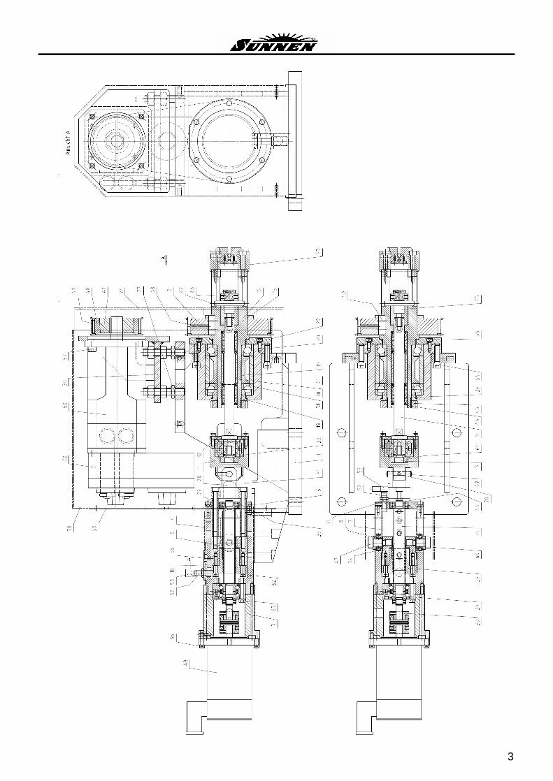
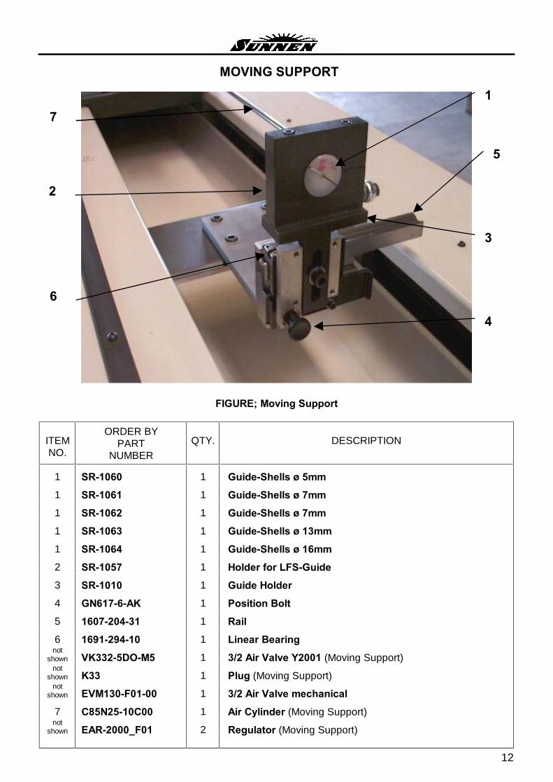
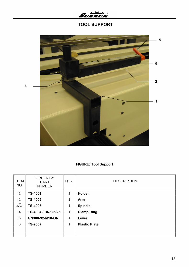
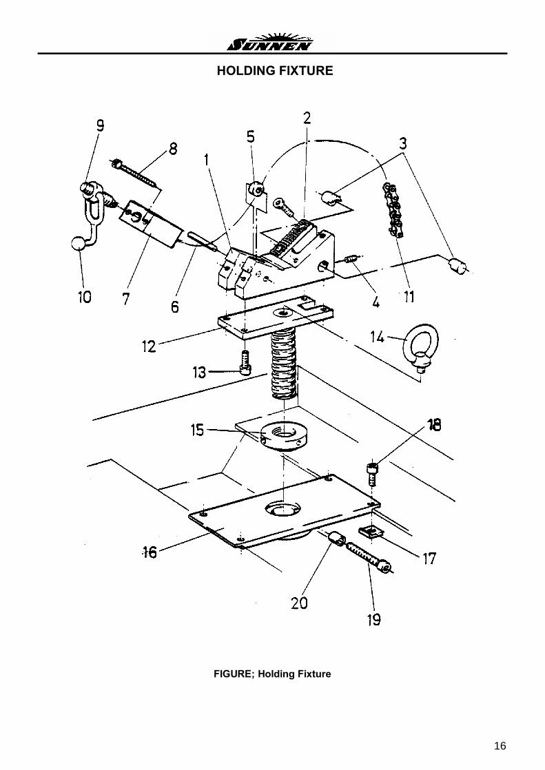
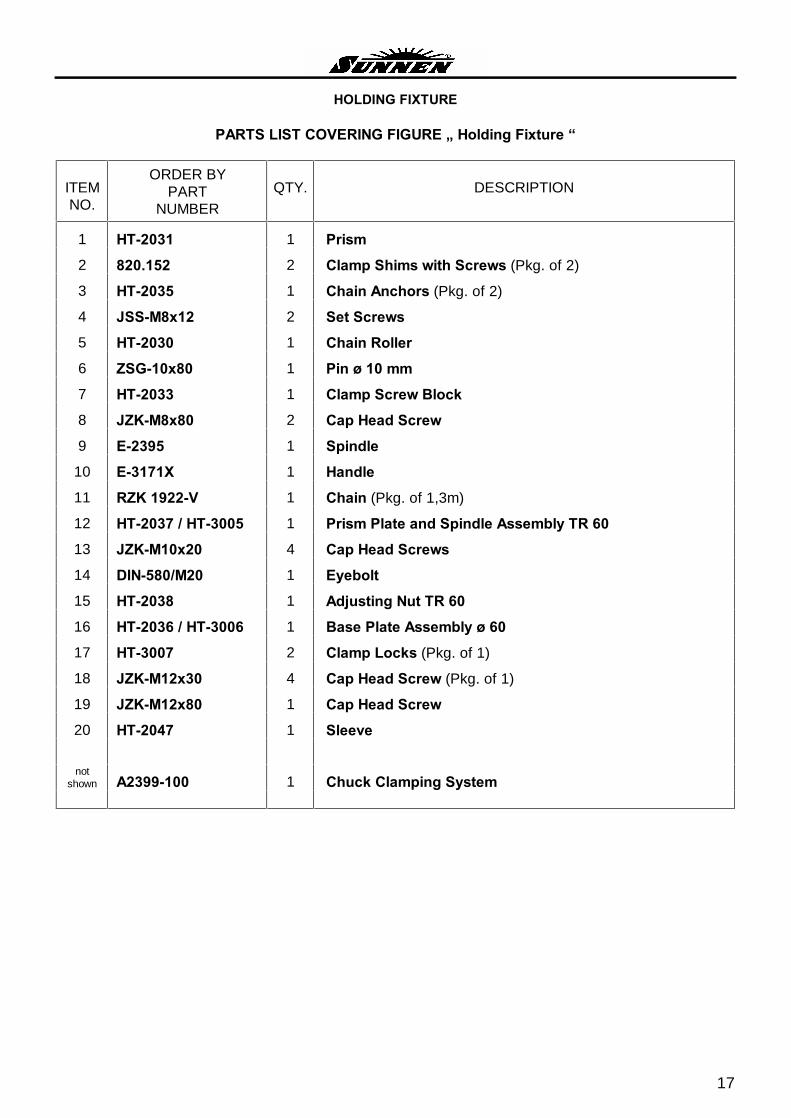
INTRODUCTION Illustrations show all major components in exploded detail. Item numbers on each illustration are keyed to he�s corresponding parts list, providing a descriptive identification of each part. The parts list includes assemblies as well as detail parts. Items listed without a part number can be optioned as a component of the complete assembly of which it is a part. SUNNEN AG reserves the right to make changes, without notice, to materials, specifications, colors, designs and accessories includes with units.
HOW TO ORDER When ordering replacement parts are sure to include the following information to insure prompt shipment of correct parts:
1. The part number and description of each part desired, obtained from this parts catalog.
2. The quantity of each part desired.
3. The voltage, frequency and phases, when ordering electrical parts.
4. The model and serial number of the honing machine, obtained from the nameplate, when there is any question concerning a part.
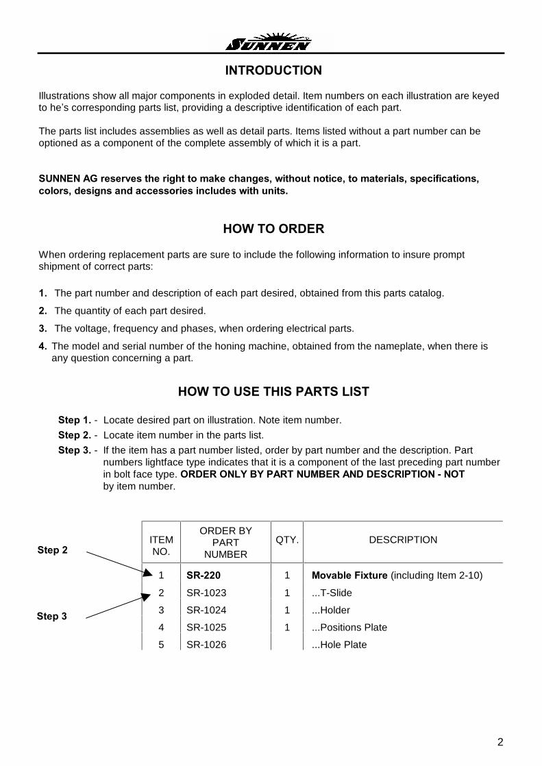
HOW TO USE THIS PARTS LIST
Step 1. - Locate desired part on illustration. Note item number.
Step 2. - Locate item number in the parts list.
Step 3. - If the item has a part number listed, order by part number and the description. Part numbers lightface type indicates that it is a component of the last preceding part number in bolt face type. ORDER ONLY BY PART NUMBER AND DESCRIPTION - NOT by item number.
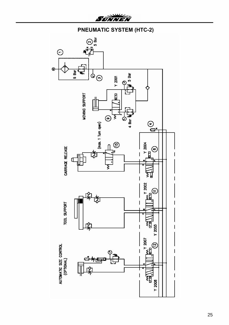
NOTE: The setting of the HIGH PRESSURE RELIEF VALVE is: 45 psi (3.1 bar) The setting of the LOW PRESSURE RELIEF VALVE is: 10 psi (0.7 bar)
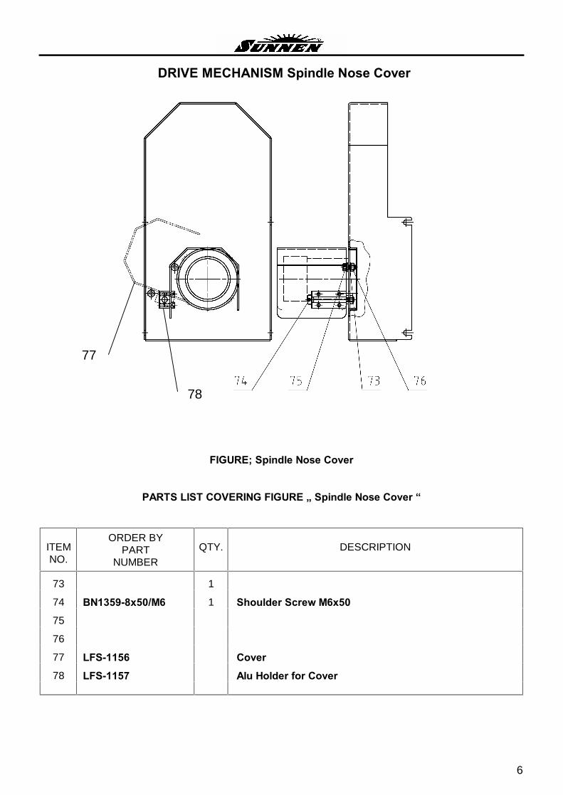
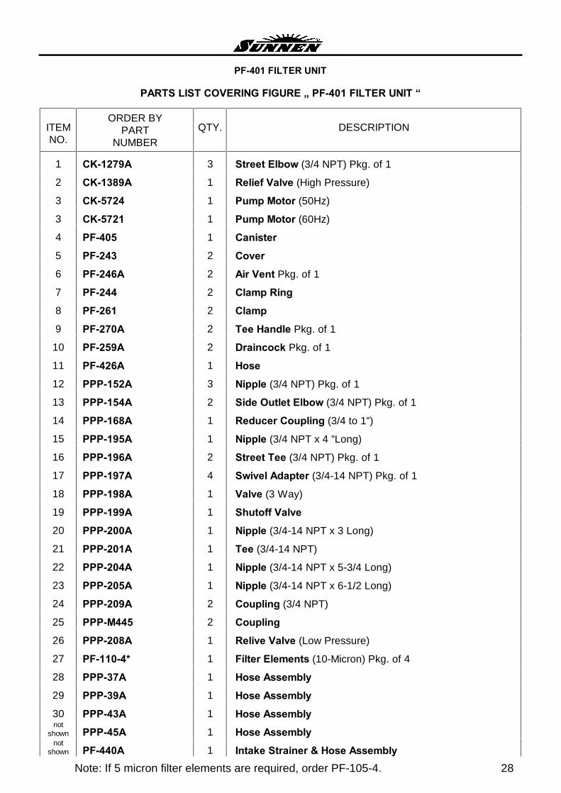
FIGURE; PF-401 FILTER UNIT
Note: If 5 micron filter elements are required, order PF-105-4. 28
PF-401 FILTER UNIT
PARTS LIST COVERING FIGURE � PF-401 FILTER UNIT �
ITEM NO.
ORDER BY PART
NUMBER
QTY.
DESCRIPTION
1 CK-1279A 3 Street Elbow (3/4 NPT) Pkg. of 1
2 CK-1389A 1 Relief Valve (High Pressure)
3 CK-5724 1 Pump Motor (50Hz)
3 CK-5721 1 Pump Motor (60Hz)
4 PF-405 1 Canister
5 PF-243 2 Cover
6 PF-246A 2 Air Vent Pkg. of 1
7 PF-244 2 Clamp Ring
8 PF-261 2 Clamp
9 PF-270A 2 Tee Handle Pkg. of 1
10 PF-259A 2 Draincock Pkg. of 1
11 PF-426A 1 Hose
12 PPP-152A 3 Nipple (3/4 NPT) Pkg. of 1
13 PPP-154A 2 Side Outlet Elbow (3/4 NPT) Pkg. of 1
14 PPP-168A 1 Reducer Coupling (3/4 to 1�)
15 PPP-195A 1 Nipple (3/4 NPT x 4 �Long)
16 PPP-196A 2 Street Tee (3/4 NPT) Pkg. of 1
17 PPP-197A 4 Swivel Adapter (3/4-14 NPT) Pkg. of 1
18 PPP-198A 1 Valve (3 Way)
19 PPP-199A 1 Shutoff Valve
20 PPP-200A 1 Nipple (3/4-14 NPT x 3 Long)
21 PPP-201A 1 Tee (3/4-14 NPT)
22 PPP-204A 1 Nipple (3/4-14 NPT x 5-3/4 Long)
23 PPP-205A 1 Nipple (3/4-14 NPT x 6-1/2 Long)
24 PPP-209A 2 Coupling (3/4 NPT)
25 PPP-M445 2 Coupling
26 PPP-208A 1 Relive Valve (Low Pressure)
27 PF-110-4* 1 Filter Elements (10-Micron) Pkg. of 4
28 PPP-37A 1 Hose Assembly
29 PPP-39A 1 Hose Assembly
30 PPP-43A 1 Hose Assembly not
shown PPP-45A 1 Hose Assembly not
shown PF-440A 1 Intake Strainer & Hose Assembly
29
* NOTES
NOTES
SUNNEN®
reserves the right to change or revise specifications and product design in connection with any feature of our products contained herein. Such changes do not entitle the buyer to corresponding changes, improvements, additions, or replacements for equipment, supplies or accessories previously sold. Information contained herein is considered to be accurate based on available information at the time of printing. Should any discrepancy of information arise, Sunnen recommends that the user verify the discrepancy with Sunnen before proceeding.