> REPLACE THIS LINE WITH YOUR PAPER IDENTIFICATION NUMBER < 1 Analysis of UAV Communications in Cell-Free Massive MIMO systems Carmen D’Andrea, Member, IEEE, Adrian Garcia-Rodriguez, Member, IEEE, Giovanni Geraci, Senior Member, IEEE, Lorenzo Galati Giordano, Member, IEEE, and Stefano Buzzi, Senior Member, IEEE We study support for unmanned aerial vehicle (UAV) communications through a cell-free massive MIMO architecture, wherein a large number of access points (APs) is deployed in place of large co-located massive MIMO arrays. We consider also a variation of the pure cell-free architecture by applying a user-centric association approach, where each user is served only from a subset of APs in the network. Under the general assumption that the propagation channel between the mobile stations, either UAVs or ground users (GUEs), and the APs follows a Ricean distribution, we derive closed form spectral efficiency lower bounds for uplink and downlink with linear minimum mean square error channel estimation. We consider several power allocation and user scheduling strategies for such a system, and, among these, also minimum-rate maximizing power allocation strategies to improve the system fairness. Our numerical results reveal that cell-free massive MIMO architecture and its low-complexity user-centric alternative may provide better performance than a traditional multi-cell massive MIMO network deployment. Index Terms—Cell-free massive MIMO, Ricean fading channel, spectral efficiency, power allocation, UAV communications, user- centric I. INTRODUCTION U Nmanned aerial vehicles (UAVs)—also referred to as drones—have attracted a great deal of attention in the last few years, both in industry and accademia, due to their ability of performing a wide variety of critical tasks efficiently and in an automated manner. The integration of UAVs in wireless communication networks has thus become a hot research area, mainly with two different approaches [1]–[7]. The first research approach focuses on the services that UAVs can provide to wireless networks, since UAVs can be regarded as moving access points (APs). With this perspective, UAVs can be used to increase the network capacity on-demand, fill network coverage holes, fastly deploy a mobile network archi- tecture in the presence of a catastrophic event, etc. [8]–[11]. The second research approach focuses on the communications services that wireless networks can provide to UAVs [12]–[17]. Considering the latter approach, [18]–[22] have recently inves- tigated the use of massive MIMO (mMIMO) to support UAVs cellular communications, showing that equipping base stations (BSs) with large antenna arrays dramatically increases—with respect to a traditional cellular deployment—the probability of meeting the stringent reliability requirements of the UAVs command and control (C&C) links. Additionally, reference [23] proposed a new 3D channel model network-connected UAVs and presented a coverage analysis applicable to different network deployments. Carmen D’Andrea and Stefano Buzzi are with the Department of Electrical and Information Engineering, University of Cassino and Southern Lazio, I-03043 Cassino, Italy (email:{buzzi, carmen.dandrea} @unicas.it) and also with the Consorzio Nazionale Interuniversitario per le Telecomunicazioni (CNIT ), I-43124 Parma, Italy. Adrian Garcia-Rodriguez and Lorenzo Galati Giordano are with Nokia Bell Labs, Dublin, Ireland, {adrian.garcia_rodriguez, lorenzo.galati_giordano}@nokia-bell-labs.com. Giovanni Geraci is with Uni- versitat Pompeu Fabra, Barcelona, Spain, [email protected]. The work of G. Geraci was partly supported by MINECO under Project RTI2018- 101040-A-I00 and by the Postdoctoral Junior Leader Fellowship Programme from “la Caixa” Banking Foundation. In parallel to the research on UAV communications, there has been growing interest about cell-free (CF) mMIMO de- ployments [24], wherein large co-located antenna arrays are substituted by a large number of simpler APs equipped with few antennas and reduced signal processing capabilities. In the CF mMIMO architecture, the APs are connected via a backhaul network to a central processing unit (CPU), which sends to the APs the data symbols to be transmitted to the users and receives soft estimates of the received data symbols from all APs. Neither channel estimates nor beamforming vectors are propagated through the backhaul network, and the time- division-duplex protocol is used to exploit uplink/downlink channel reciprocity. Radio stripes could enable the practical deployment of these systems [25], [26]. The results in [24] show that the CF approach provides better performance than a small-cell system in terms of 95%-likely per-user throughput. Additionally, [27]–[29] have recently introduced a user-centric (UC) virtual-cell massive MIMO approach to CF mMIMO, as- suming that each AP does not serve all the users in the system, but only a subset of them. Overall, the UC approach could be deemed as a low-complexity alternative to CF mMIMO, since APs focus their available resources on the users that will benefit the most from them. CF mMIMO network deployments with UC association rules between the users and the APs are expected to be one of the key technologies for future beyond-5G and 6G wireless networks. Recently, article [30] has discussed some scalability aspects of CF mMIMO systems presenting a scalable implementation of the UC association rule, where one user can be associated to some APs connected to different CPUs. Paper contribution This work, extending preliminary results reported in the conference paper [31], analyzes and compares the CF and UC network behaviors in the presence of communication with both UAVs and legacy ground users (GUEs). The paper contributions can be summarized as follows: arXiv:1909.02485v2 [cs.IT] 10 Jan 2020
Transcript
> REPLACE THIS LINE WITH YOUR PAPER IDENTIFICATION NUMBER < 1
Analysis of UAV Communications inCell-Free Massive MIMO systems
Carmen D’Andrea, Member, IEEE, Adrian Garcia-Rodriguez, Member, IEEE, Giovanni Geraci, Senior Member, IEEE,Lorenzo Galati Giordano, Member, IEEE, and Stefano Buzzi, Senior Member, IEEE
We study support for unmanned aerial vehicle (UAV) communications through a cell-free massive MIMO architecture, wherein alarge number of access points (APs) is deployed in place of large co-located massive MIMO arrays. We consider also a variation ofthe pure cell-free architecture by applying a user-centric association approach, where each user is served only from a subset of APsin the network. Under the general assumption that the propagation channel between the mobile stations, either UAVs or groundusers (GUEs), and the APs follows a Ricean distribution, we derive closed form spectral efficiency lower bounds for uplink anddownlink with linear minimum mean square error channel estimation. We consider several power allocation and user schedulingstrategies for such a system, and, among these, also minimum-rate maximizing power allocation strategies to improve the systemfairness. Our numerical results reveal that cell-free massive MIMO architecture and its low-complexity user-centric alternative mayprovide better performance than a traditional multi-cell massive MIMO network deployment.
Index Terms—Cell-free massive MIMO, Ricean fading channel, spectral efficiency, power allocation, UAV communications, user-centric
I. INTRODUCTION
UNmanned aerial vehicles (UAVs)—also referred to asdrones—have attracted a great deal of attention in the
last few years, both in industry and accademia, due to theirability of performing a wide variety of critical tasks efficientlyand in an automated manner. The integration of UAVs inwireless communication networks has thus become a hotresearch area, mainly with two different approaches [1]–[7].The first research approach focuses on the services that UAVscan provide to wireless networks, since UAVs can be regardedas moving access points (APs). With this perspective, UAVscan be used to increase the network capacity on-demand, fillnetwork coverage holes, fastly deploy a mobile network archi-tecture in the presence of a catastrophic event, etc. [8]–[11].The second research approach focuses on the communicationsservices that wireless networks can provide to UAVs [12]–[17].Considering the latter approach, [18]–[22] have recently inves-tigated the use of massive MIMO (mMIMO) to support UAVscellular communications, showing that equipping base stations(BSs) with large antenna arrays dramatically increases—withrespect to a traditional cellular deployment—the probabilityof meeting the stringent reliability requirements of the UAVscommand and control (C&C) links. Additionally, reference[23] proposed a new 3D channel model network-connectedUAVs and presented a coverage analysis applicable to differentnetwork deployments.
Carmen D’Andrea and Stefano Buzzi are with the Department ofElectrical and Information Engineering, University of Cassino and SouthernLazio, I-03043 Cassino, Italy (email:{buzzi, carmen.dandrea} @unicas.it) andalso with the Consorzio Nazionale Interuniversitario per le Telecomunicazioni(CNIT), I-43124 Parma, Italy. Adrian Garcia-Rodriguez and Lorenzo GalatiGiordano are with Nokia Bell Labs, Dublin, Ireland, {adrian.garcia_rodriguez,lorenzo.galati_giordano}@nokia-bell-labs.com. Giovanni Geraci is with Uni-versitat Pompeu Fabra, Barcelona, Spain, [email protected]. The workof G. Geraci was partly supported by MINECO under Project RTI2018-101040-A-I00 and by the Postdoctoral Junior Leader Fellowship Programmefrom “la Caixa” Banking Foundation.
In parallel to the research on UAV communications, therehas been growing interest about cell-free (CF) mMIMO de-ployments [24], wherein large co-located antenna arrays aresubstituted by a large number of simpler APs equipped withfew antennas and reduced signal processing capabilities. Inthe CF mMIMO architecture, the APs are connected via abackhaul network to a central processing unit (CPU), whichsends to the APs the data symbols to be transmitted to the usersand receives soft estimates of the received data symbols fromall APs. Neither channel estimates nor beamforming vectorsare propagated through the backhaul network, and the time-division-duplex protocol is used to exploit uplink/downlinkchannel reciprocity. Radio stripes could enable the practicaldeployment of these systems [25], [26]. The results in [24]show that the CF approach provides better performance thana small-cell system in terms of 95%-likely per-user throughput.Additionally, [27]–[29] have recently introduced a user-centric(UC) virtual-cell massive MIMO approach to CF mMIMO, as-suming that each AP does not serve all the users in the system,but only a subset of them. Overall, the UC approach couldbe deemed as a low-complexity alternative to CF mMIMO,since APs focus their available resources on the users that willbenefit the most from them. CF mMIMO network deploymentswith UC association rules between the users and the APsare expected to be one of the key technologies for futurebeyond-5G and 6G wireless networks. Recently, article [30]has discussed some scalability aspects of CF mMIMO systemspresenting a scalable implementation of the UC associationrule, where one user can be associated to some APs connectedto different CPUs.
Paper contributionThis work, extending preliminary results reported in the
conference paper [31], analyzes and compares the CF andUC network behaviors in the presence of communicationwith both UAVs and legacy ground users (GUEs). The papercontributions can be summarized as follows:
arX
iv:1
909.
0248
5v2
[cs
.IT
] 1
0 Ja
n 20
20
> REPLACE THIS LINE WITH YOUR PAPER IDENTIFICATION NUMBER < 2
1) Assuming a Ricean channel model for both the GUEsand the UAVs, and linear minimum mean square error(LMMSE) channel estimation, we derive closed-formexpressions of the lower-bound of the achievable spectralefficiencies with matched filtering for both the uplink anddownlink.
2) We consider and evaluate the performance of severalpower allocation strategies for the considered architec-tures:- For the downlink, i) we consider a proportional power
allocation strategy, ii) we introduce a waterfilling-basedpower allocation for the CF approach only, and iii) wederive a power control rule aimed at the maximizationof the minimum of the spectral efficiencies across theusers, using the successive lower-bound maximizationtechnique [32]–[34]. Since experimental evaluation ofthese power control rules will show that UAVs tendto take a larger share of resource due to their morefavorable propagation conditions, these resource allo-cation rules are also revisited under the constraint thatthe UAVs and the GUEs share a pre-determined andfixed set of the system resources.
- For the uplink, we derive and examine the performanceof both i) a fractional power control rule, and ii)a minimum-rate maximizing with resource allocationstrategy.
3) To the best of our knowledge, our article performs thefirst evaluation of CF and UC network deploymentswith cellular-connected UAVs, and the comparison ofthese architectures with a customary multi-cell mMIMOnetwork. Our results reveal that CF and UC architecturescan outperform multi-cell mMIMO networks for the largemajority of UAVs and GUEs in the network as long asadequate power and resource allocation procedures areimplemented.
The remainder of this paper is organized as follows. Sec. IIcontains the description of the considered system model andthe communication process. Sec. III includes the derivationsof the uplink and downlink spectral efficiency bounds. InSections IV-A and IV-B several power allocation strategies aredetailed for the downlink and for the uplink, respectively. Sec.V contains the numerical results and presents the key insightsof our analysis, while our concluding remarks are given inSec. VI.
Notation: In this paper, the following notation is used. Ais a matrix; a is a vector; a is a scalar. The operators (·)T ,(·)−1, and (·)H stand for transpose, inverse and, conjugatetranspose, respectively. The determinant of the matrix A isdenoted as |A| and IP is the P ×P identity matrix. The traceof the matrix A is denoted as tr(A). The statistical expectationoperator is denoted as E[·], the real part operator is denotedas <{·}; CN
(µ, σ2
)denotes a complex circularly symmetric
Gaussian random variable (RV) with mean µ and variance σ2.
II. SYSTEM MODELA. Cell-Free Network Topology
As depicted in Fig. 1(a), we consider a network that consistsof outdoor APs, GUEs, and UAVs, whose sets are denotedby A, G, and U , and have cardinalities NA, NG, and NU,respectively. In the following, we let the term users denoteboth GUEs and UAVs. The NA APs are connected by meansof a backhaul network to a CPU wherein data-decoding isperformed1. In keeping with the approach of [24], [37], allcommunications take place on the same frequency band, i.e.uplink and downlink are separated through time-division-duplex (TDD).
We assume the UAVs and GUEs are equipped with a singleantenna, while each AP is equipped with a uniform linear array(ULA) comprised of NAP antennas. We let K = G ∪ U , anddefine K , NG + NU as the total number of users in thesystem. Let us also denote by Ka the set of users served bythe a-th AP on a given physical resource block (PRB), and byKa its cardinality. The set of APs serving user k is denoted byAk. The set of users associated to each AP can be determinedaccording to several criteria. In general, the user associationcan be formulated as an integer optimization problem, whosesolution is not straightforward. In this paper, we consider thetwo following a-priori approaches.
1) CF approachIn the CF approach, each AP communicates with all the
users in the system, i.e., we have that Ka = K, ∀ a =1, . . . , NA and the set Ak = A, ∀ k = 1, . . . ,K.
2) UC approachIn the UC approach, the k-th user is served by the Ak
APs that it receives with best average channel conditions. Letβk,a characterize the scalar coefficient modeling the channelpath-loss and shadowing effects between the k-th user andthe a-th AP and Ok : {1, . . . , NA} → {1, . . . , NA} denotethe sorting operator for the vector [βk,1, . . . , βk,NA
], such thatβk,Ok(1) ≥ βk,Ok(2) ≥ . . . ≥ βk,Ok(NA). The set Ak of theAk APs serving the k-th user is then given by
Ak = {Ok(1), Ok(2), . . . , Ok(Ak)}. (1)
Consequently, the set of users served by the a-th AP is definedas Ka = {k : a ∈ Ak}.
B. Propagation Channel
We denote by gk,a ∈ CNAP the channel between the k-thuser and the a-th AP. Throughout the paper we characterizethe small-scale fading through a Ricean fading model, whichconsists of a dominant line-of-sight (LOS) component and aRayleigh–distributed factor modelling the rich-scattered mul-tipath. The channel between the k-th generic user and the a-thAP is thus written as
gk,a =
√βk,a
Kk,a + 1
[√Kk,ae
jϑk,aa (θk,a) + hk,a
], (2)
1In this article, we assume perfect links between the APs and the CPU,the consideration of limited backhaul links is out of the scope of this paper,an interested reader can be referred to papers [35], [36].
> REPLACE THIS LINE WITH YOUR PAPER IDENTIFICATION NUMBER < 3
(a) . (b) .
Figure 1: In (a) a CF network supporting both ground and UAV users, and in (b) the reference system for the phase rotation evaluation inthe channel between a generic AP-UAV pair.
where Kk,a is the Ricean K-factor, hk,a ∈ CNAP contains thesmall-scale fading i.i.d. CN (0, 1) coefficients between the a-thAP and the k-th user, and ϑk,a follows a uniform distributionin [0, 2π], denoting the random phase offset for the directpath. Moreover, a (θk,a) ∈ CNAP represents the steering vectorevaluated at the angle θk,a, which characterizes the directpath between the a-th AP and the k-th user. As illustratedin Fig. 1b, denoting by d the antenna spacing at the AP,and by za,q and zk the 3D vectors containing the positionof the q-th antenna element at the a-th AP and of the k-thuser, respectively, the `-th entry of the vector a(θk,a) canbe written as [a (θk,a)]` = e−j
2πλ (‖za,1−zk‖−‖za,`−zk‖), with
` = 1, . . . , NAP.We consider that the Ricean K-factor Kk,a depends on the
probability that the link between the k-th user and the a-th APpLOS (dk,a) is LOS, which, in turn, depends on the link lengthdk,a following [38]. We thus have Kk,a =
pLOS(dk,a)1−pLOS(dk,a)
.
C. The Communication Process: Uplink Training
Let us denote by τc the dimension in time/frequencysamples of the channel coherence length, and by τp < τcthe dimension of the uplink training phase. We also defineφk ∈ Cτp as the pilot sequence sent by user k, and assumethat ‖φk‖2 = 1∀k. The signal received at the a-th AP duringthe training phase Ya ∈ CNAP×τp can be therefore expressedas
Ya =∑k∈K
√ηkgk,aφ
Hk + Wa , (3)
where ηk denotes the power employed by the k-th user duringthe training phase, and Wa ∈ CNAP×τp contains the thermalnoise contribution and out-of-cell interference at the a-th AP,with i.i.d. CN (0, σ2
w) RVs as entries.From the observable Ya, and exploiting the knowledge
of the users’ pilot sequences, the a-th AP can estimate thechannel vectors {gk,a}k∈Ka based on the statistics
yk,a = Yaφk =√ηkgk,a +
K∑i=1i 6=k
√ηigi,aφ
Hi φk + Waφk .
(4)
Specifically, assuming knowledge of the large-scale fadingcoefficients βk,a as in [24], and of the vectors a (θk,a) ∀ a, k,the LMMSE estimate of {gk,a}k∈Ka of the channel gk,a isgiven by2
gk,a = Dk,a yk,a , (5)
where
Dk,a =√ηkGk,aB
−1k,a ∈ CNAP×NAP ,
Gk,a =βk,a
Kk,a+1
[Kk,aa (θk,a)aH (θk,a) + INAP
],
Bk,a =∑i∈K ηiβi,aGi,a
∣∣φHi φk∣∣2 + σ2
wINAP
D. The Communication Process: Downlink Data Transmis-sion
The APs treat the channel estimates as the true channels andperform conjugate beamforming on the downlink. The signaltransmitted by the a-th AP in a generic symbol interval is thefollowing NAP-dimensional vector
sa =∑k∈Ka
√ηDLk,agk,ax
DLk , (6)
with xDLk being the downlink data-symbol for the k-th user,
and ηDLk,a a scalar coefficient controlling the power transmitted
by the a-th AP to the k-th user. Letting ηDLa denote the overall
transmitted power by the a-th AP, the normalized transmitpower must satisfy the constraint
E[‖sa‖2
]=∑k∈Ka
ηDLk,aγk,a ≤ ηDL
a , (7)
where γk,a = E[gHk,agk,a
]=√ηktr (Gk,aDk,a) .
2Note that we are assuming at the APs the knowledge of the vectorsa(θk,a
), i.e., of the directions of arrival of the main LoS paths. This
assumption is realistic because the main direction of arrival can be easilyestimated at the APs and it changes approximately on the time-scale of thevariation of the path-loss and shadow fading coefficients βk,a.
> REPLACE THIS LINE WITH YOUR PAPER IDENTIFICATION NUMBER < 4
Subsequently, each user receives phase-aligned contribu-tions from all APs. In particular, the k-th user receives thesoft estimate for the data symbol
xDLk =
∑a∈A
gHk,asa + zk =∑a∈Ak
√ηDLk,ag
Hk,agk,ax
DLk
+∑j∈K\k
∑a∈Aj
√ηDLj,a g
Hk,agj,ax
DLj + zk ,
(8)
with zk being the CN (0, σ2z) additive white Gaussian noise
(AWGN).
E. The Communication Process: Uplink Data Transmission
In uplink, users send their data symbols without anychannel-dependent phase offset. As a result, the signal ya ∈CNAP received at the a-th AP in a generic symbol interval canbe expressed as
ya =∑k∈K
√ηULk gk,ax
ULk + wa , (9)
with ηULk and xUL
k representing the uplink transmit powerand the data symbol of the k-th user, respectively, and wa ∼CN (0, σ2
wI) ∈ CNAP the AWGN vector.Subsequently, each AP decodes the data transmitted by users
in Ka. The a-th AP thus forms, for each k ∈ Ka, the statisticsta,k = gHk,aya and sends them to the CPU. Accordingly, theCPU is able to derive soft estimates
xULk =
∑a∈Ak
ta,k , k ∈ K (10)
of the data sent by the users.
III. SPECTRAL EFFICIENCY BOUNDS
In this section, we report lower and upper spectral efficiencybounds both for the downlink and uplink data transmissionphases.
A. Downlink Data Transmission
1) Lower BoundA LB for the downlink spectral efficiency can be also com-
puted, based on the assumption that each user has knowledgeof the channel statistics but not of the channel realizations.The received signal in (8) can be thus rewritten as
xDLk = E
[∑a∈Ak
√ηDLk,ag
Hk,agk,a
]︸ ︷︷ ︸
Dk
xDLk
+
(∑a∈Ak
√ηDLk,ag
Hk,agk,a − E
[∑a∈Ak
√ηDLk,ag
Hk,agk,a
])︸ ︷︷ ︸
Bk
xDLk
+∑j∈K\k
∑a∈Aj
√ηDLj,a g
Hk,agj,a︸ ︷︷ ︸
Ik,j
xDLj + zk ,
(11)
where Dk, Bk, and Ik,j represent the strength of desiredsignal, the beamforming gain uncertainty, and the interferencecaused by the k-th user, respectively. We treat the sum ofthe second, third, and fourth summand in (11) as “effectivenoise” as in references [24], [39], [40]. By using the factthat uncorrelated Gaussian noise represents the worst case, weobtain the following LB for the downlink spectral efficiencyof the k-th user in the system:
SEDLk,LB =
τdτc
log2
1 +|Dk|2
E[|Bk|2
]+∑j∈K\k
E[|Ik,j |2
]+ σ2
z
,
(12)where τd = τc − τp − τu and τu are the lengths (in time-frequency samples) of the downlink and uplink data transmis-sion phases in each coherence interval, respectively.
Eq. (12) is deterministic and contains several expectationsover the random channel realizations. For the general case,these expectations are not available in closed form but canbe computed through Monte Carlo simulations. Conversely,for the case of conjugate beamforming and LMMSE channelestimation, a closed form expression for the spectral efficiencyLB can be obtained. We have indeed the following result:
Lemma 1: A LB for the downlink spectral efficiency inthe case of conjugate beamforming and LMMSE channelestimation is given by
SEDLk,LB =
τdτc
log2
(1 + SINRk,DL
), (14)
where SINRk,DL is shown in (13) at the top of the next page,and
δ(j)k,a =
(βk,a
Kk,a + 1
)2
tr2 (Dj,a)
+2Kk,a
(βk,a
Kk,a + 1
)2
<{
tr(aH (θk,a)Dj,aa (θk,a)DH
j,a
)}.
(15)Proof: The proof of Lemma 1 is based on the application
of the use-and-then-forget (UatF) bound [41]. The completedetails are reported in Appendix VI-A. �
2) Upper BoundTo provide an intuition about the tightness of the LB
derived in Sec. III-A1, we also include a UB of the achievabledownlink spectral efficiency here. Specifically, given the ex-pression in (8) an upper bound (UB) for the achievable spectralefficiency can be obtained as [42]
SEDLk,UB =
τdτc
E
1 +
∣∣∣∣∣ ∑a∈Ak
√ηDLk,ag
Hk,agk,a
∣∣∣∣∣2
∑j∈K\k
∣∣∣∣∣∣∑a∈Aj
√ηDLj,a g
Hk,agj,a
∣∣∣∣∣∣2
+σ2z
. (16)
The expectation in (16) is made over the fast fading channelrealizations.
> REPLACE THIS LINE WITH YOUR PAPER IDENTIFICATION NUMBER < 5
SINRk,DL =
(∑a∈Ak
√ηDLk,aγk,a
)2
×
{∑a∈Ak
ηDLk,a
(ηkδ
(k)k,a − γ
2k,a
)+∑j∈K
√ηj∑a∈Aj
ηDLj,a tr
(Gj,aD
Hj,aGk,a
)+σ2
z +∑j∈K\k
ηk
{ ∑a∈Aj
[ηDLj,a δ
(j)k,a +
∑b∈Ajb 6=a
√ηDLj,a
√ηDLj,b tr (Dj,aGk,a) tr
(DHj,bGk,b
) ]} ∣∣φHk φj∣∣2}−1 (13)
B. Uplink Data Transmission
1) Lower BoundUsing straightforward manipulations, (10) can be re-written
as
xULk =
∑a∈Ak
√ηULk gHk,agk,ax
ULk
+∑j∈K\k
∑a∈Ak
√ηULj gHk,agj,ax
ULj +
∑a∈Ak
gHk,awa.
(17)In order to derive a LB for the uplink spectral efficiency,
we assume that the CPU relies only on statistical knowledgeof the channel coeficients when performing the detection, sothat (17) can be re-written as
xULk = E
[∑a∈Ak
√ηULk gHk,agk,a
]︸ ︷︷ ︸
Dk
xULk
+
(∑a∈Ak
√ηULk gHk,agk,a − E
[∑a∈Ak
√ηULk gHk,agk,a
])︸ ︷︷ ︸
Bk
xULk
+∑j∈K\k
∑a∈Ak
√ηULj gHk,agj,a︸ ︷︷ ︸Ik,j
xULj +
∑a∈Ak
gHk,awa︸ ︷︷ ︸Nk
.
(18)Again we model the sum of the second, third, and fourthsummand as “effective noise” and use the worst-case gaussianassumption, which leads to the following UB for the uplinkspectral efficiency of the k-th user:
SEULk,LB=
τuτc
log2
1+
∣∣∣Dk
∣∣∣2E[∣∣∣Bk∣∣∣2]+∑
j∈K\k
E[∣∣∣Ik,j∣∣∣2]+E [∣∣∣Nk∣∣∣2]
.
(19)As for the downlink, Eq. (19) is deterministic and contains
several expectations over the random channel realizations thatcan be computed, in the general case, by means of MonteCarlo simulations. Conversely, for the case in which matchedfilter detection and LMMSE channel estimation are used, aclosed-form expression can be worked out. We have indeedthe following result:
Lemma 2: Assuming that data decoding is performedthrough matched filtering and LMMSE channel estimation is
used, a LB for the k-th user uplink spectral efficiency can beexpressed as
SEULk,LB =
τuτc
log2
(1 + SINRk,UL
), (21)
where SINRk,UL is reported in (20) at the bottom of the nextpage, and
δ(k)j,a =
(βj,a
Kj,a + 1
)2
tr2 (Dk,a) +
2Kj,a
(βj,a
Kj,a + 1
)2
<{
tr(aH (θj,a)Dk,aa (θj,a)DH
k,a
)}.
(22)Proof: The proof of Lemma 2 is also based on the appli-
cation of the UatF bound [41]. The details of the proof arereported in Appendix VI-B. �
2) Upper BoundFollowing steps similar to the ones detailed above for the
downlink, a UB for the achievable spectral efficiency can beobtained as [42]
SEULk,UB =
τuτcE
1+
ηULk
∣∣∣∣∣ ∑a∈Ak
gHk,agk,a
∣∣∣∣∣2
∑j∈K\k
ηULj
∣∣∣∣∣ ∑a∈Ak
gHk,agj,a
∣∣∣∣∣2
+σ2w
∑a∈Ak
‖gk,a‖2
.(23)
IV. POWER ALLOCATION STRATEGIES
In this section we derive and describe a variety of powerallocation strategies tailored for networks with coexistingUAVs and GUEs.
A. Downlink Data Transmission
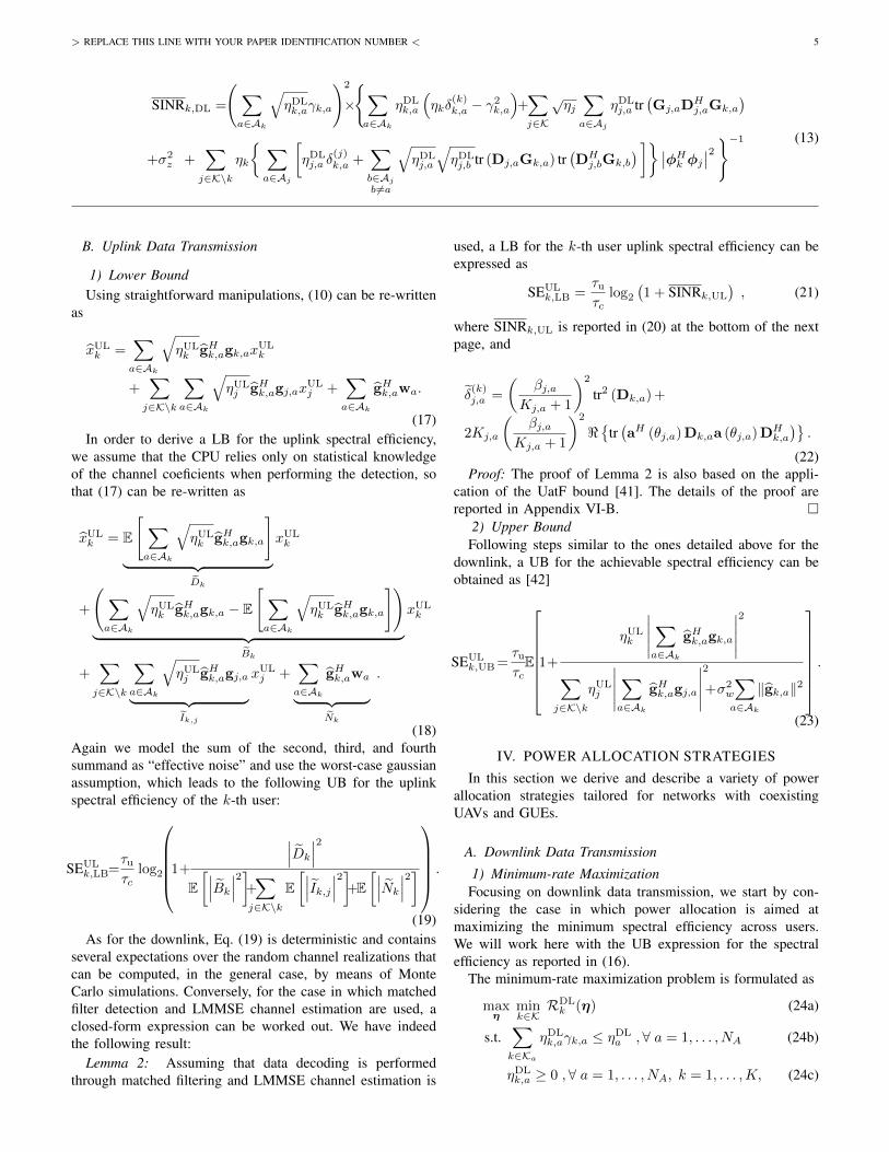
1) Minimum-rate MaximizationFocusing on downlink data transmission, we start by con-
sidering the case in which power allocation is aimed atmaximizing the minimum spectral efficiency across users.We will work here with the UB expression for the spectralefficiency as reported in (16).
The minimum-rate maximization problem is formulated as
maxη
mink∈K
RDLk (η) (24a)
s.t.∑k∈Ka
ηDLk,aγk,a ≤ ηDL
a ,∀ a = 1, . . . , NA (24b)
ηDLk,a ≥ 0 ,∀ a = 1, . . . , NA, k = 1, . . . ,K, (24c)
> REPLACE THIS LINE WITH YOUR PAPER IDENTIFICATION NUMBER < 6
where RDLk (η) = WSEDL
k,UB is the achievable downlink rate,W is the system bandwidth, and η is the KM × 1 vectorcollecting the downlink transmit powers of all APs for allusers.
In order to obtain a more tractable form, we reformulate theoptimization problem as follows
maxη
mink∈K
RDLk (η) (25a)
s.t.∑k∈Ka
ηDLk,aρ
DLa,kγk,a ≤ ηDL
a ,∀ a = 1, . . . , NA (25b)
ηDLk,a ≥ 0 ,∀ a = 1, . . . , NA, k = 1, . . . ,K, (25c)
where ρDLa,k =
∑j∈Ka
γj,a
−1 , and 0 ≤ ηDLk,a ≤ ηDL
a ,∀ a =
1, . . . , NA, k = 1, . . . ,K are the normalized transmit powers.The Problem (24) has a non-concave and non-differentiable
objective function, and therefore cannot be solved throughefficient numerical methods. The following Lemma describeshow the problem can be solved in a tractable manner.
Lemma 3: The optimization problem (24) can be solvedusing the procedure stated in Algorithm 1, where Pp is theoptimization problem
Pp : maxη
(p)a ,t
t (26a)
s.t.∑k∈Ka
ηDLk,aρ
DLa,kγk,a ≤ ηDL
a ,∀ a = 1, . . . , NA (26b)
ηDLk,a ≥ 0 ,∀ a = 1, . . . , NA, k = 1, . . . ,K, (26c)
RDLk
(η(p)a ,η
(p)a,0,η
(−p)−a
)≥ t, ∀ k = 1, . . . ,K,
(26d)
which can be easily shown to be convex for any η(p)a,0, and
therefore can be solved through standard techniques.Proof: The proof of Lemma 3 is based on the application
of the successive lower-bound maximization framework andsuccessive reformulations. The complete details and the def-inition of RDL
k
(η(p)a ,η
(p)a,0,η
(−p)−a
)are reported in Appendix
VI-C. �Finally, we also consider the case in which each AP uses a
predetermined percentage of the available power to serve theUAVs. The rationale behind this approach is based on the factthat networks operators might want to guarantee a specificquality of service for UAVs and/or GUEs. We denote by κthe fraction of the available power that each AP uses for theUAVs, and with Ga and Ua the sets of the GUEs and the UAVsserved from the a-th AP.
Algorithm 1 Minimum-rate maximization in downlink
1: Set i = 0 and choose any feasibleη(1)2 , . . . ,η
(P2)2 . . . ,η
(1)NA, . . . ,η
(PNA )
NA;
2: repeat3: for a = 1→ NA do4: for p = 1→ Pa do5: repeat6: Choose any feasible η
(p)a,0;
7: Let η(p),∗a be the solution of Pp in (26);
8: η(p)a,0 = η(p),∗
a ;9: until convergence
10: η(p)a = η(p),∗
a ;11: end for12: end for13: until convergence
Problem (26) is solved by properly choosing the blocksη(p)a , ∀p = 1, . . . , Pa, a = 1, . . . , NA that contain only GUEs
or only UAVs, using the constraints on the maximum poweras (1− κ) ηDL
a and κηDLa , respectively and
ρDLa,k =
∑j∈Ga
γj,a
−1 , if k ∈ Ga ,∑j∈Ua
γj,a
−1 , if k ∈ Ua.
(27)
The full details are omitted for the sake of brevity.2) Waterfilling Power Allocation
Next, we propose a heuristic power allocation policy in-spired by the well-known waterfilling strategy [43]. We assumethat the “noise” level for the communication between the a-thAP and the k-th user is written as Lk,a =
σ2z
γk,a, so that the
waterfilling power allocation (WFPA) strategy is expressed as
PDLk,a =
{(νa − Lk,a)
+, if k ∈ Ka ,
0 otherwise.(28)
where νa is the water level, (·)+ = max{0, ·}, and thefollowing constraint holds:∑
k∈Ka
(νa − Lk,a)+
= ηDLa . (29)
This heuristic power allocation rule forces a CF deploymentto behave like an AP-centric system, since Eq. (28) implicitlymakes a selection of the users to serve.
SINRk,UL= ηULk
(∑a∈Ak
γk,a
)2
×
{ηULk
∑a∈Ak
(ηk δ
(k)k,a − γ
2k,a
)+∑j∈K
ηULj
√ηk∑a∈Ak
tr(Gk,aD
Hk,aGj,a
)+ σ2
w
∑a∈Ak
γk,a +∑j∈K\k
ηULj ηj
{ ∑a∈Ak
[δ(k)j,a +
∑b∈Akb6=a
tr(DHk,aGj,a
)tr (Dk,bGj,b)
]} ∣∣φHj φk∣∣2}−1. (20)
> REPLACE THIS LINE WITH YOUR PAPER IDENTIFICATION NUMBER < 7
Considering the case in which each AP uses a fraction κof the available power to serve the UAVs, the WFPA rulebecomes
PDLk,a =
(ν(GUE)a − Lk,a
)+, if k ∈ Ga ,(
ν(UAV )a − Lk,a
)+, if k ∈ Ua ,
0 otherwise.
(30)
where ν(GUE)a and ν(UAV )
a are the water levels for the GUEsand the UAVs, respectively, and the following constraints areto be fulfilled.∑
k∈Ga
(ν(GUE)a − Lk,a
)+= (1− κ) ηDL
a ,∑k∈Ua
(ν(UAV )a − Lk,a
)+= κηDL
a .(31)
3) Proportional Power AllocationAs a baseline power allocation strategy, we also consider
proportional power allocation (PPA). Letting PDLk,a = ηDL
k,aγk,adenote the power transmitted by the a-th AP to the k-th user,we have the policy:
PDLk,a =
ηDLa
γk,a∑j∈Ka
γj,a, if k ∈ Ka,
0 otherwise.
(32)
The above strategy is such that the generic a-th AP sharesits power ηDL
a in a way that is proportional to the estimatedchannel strengths. In this way, users with good channel coef-ficients will receive a larger share of the transmit power thanusers with bad channels.
Additionally, we consider the case in which each AP usesa fraction κ of the available power to serve the UAVs. Thisis because UAVs tend to absorb a large share of the systemresources in the case of proportional power allocation, due tothe fact that they generally enjoy stronger channels than GUEs,as later demonstrated in the numerical results. Accordingly, thedivision of the power resources provides a further degree offlexibility for networks operators and facilitates guaranteeingthe GUEs’ performance. Following this approach, the PPA rulecan be written as
PDLk,a =
(1− κ) ηDLa
γk,a∑j∈Ga
γj,a, if k ∈ Ga ,
κηDLa
γk,a∑j∈Ua
γj,a, if k ∈ Ua ,
0 otherwise .
(33)
B. Uplink Data Transmission
1) Minimum-rate MaximizationAlso for the uplink, a power allocation strategy based on
the minimum-rate maximization can be conceived. We are thusfaced with the optimization problem
Algorithm 2 Minimum-rate maximization in uplink
1: Set i = 0 and choose any feasible η(2), . . . , η(Q);2: repeat3: for q = 1→ Q do4: repeat5: Choose any feasible η
k,UB is the achievable uplink rate andη is the K × 1 vector collecting the uplink transmit powersof all the users. Using similar arguments as done for thedownlink and defining the R-dimensional variable blocks η(q),q = 1, . . . , Q, collecting the q-th block of uplink transmitpowers, the minimum-rate maximization with respect to thevariable block η(q) is cast as
maxη(q),t
t (35a)
s.t. 0 ≤ ηULk ≤ Pmax,k ,∀ k = 1, . . . ,K. (35b)
RULk (η(q), η(−q)) ≥ t, ∀ k = 1, . . . ,K. (35c)
Letting RULk be a suitable upper bound to RUL
k , following asimilar approach as in Section IV-A1, Problem (35) can betackled by the sequential optimization framework, by definingthe q-th problem of the sequence:
Pq : maxη(q),t
t (36a)
s.t. 0 ≤ ηULk ≤ Pmax,k ,∀ k = 1, . . . ,K. (36b)
RULk
(η(q), η
(q)0 , η(−q)
)≥ t, ∀ k = 1, . . . ,K.
(36c)
The resulting power control procedure can be stated as inAlgorithm 2.
2) Fractional Power ControlWe adopt fractional power control (FPC) as the reference
power adjustment rule for uplink data transmission [44],[45]. With FPC, the transmit power of the k-th user can beexpressed as ηUL
k = min(Pmax,k, P0ζ
−αk
), where Pmax,k is
the maximum k-th user transmit power, and P0 is a cell-specific parameter configurable by the serving AP, α is a pathloss compensation factor. Moreover, ζk captures the large scalefading that the k-th user experiences to the serving APs in Ak,and is obtained as ζk =
√∑a∈Ak tr (Gk,a).
V. NUMERICAL RESULTS AND KEY INSIGHTSThe simulation setup for the numerical results is detailed in
the following. We consider a square area of 1 km2 wrapped
> REPLACE THIS LINE WITH YOUR PAPER IDENTIFICATION NUMBER < 8
Table I: Cell-free system parameters
DeploymentAP distribution Horizontal: uniform, vertical: 10 mGUE distribution Horizontal: uniform, vertical: 1.65 mUAV distribution Horizontal: uniform, vertical uniform be-
tween 22.5 m and 300 m [45]
PHY and MACCarrier frequency,bandwidth
f0 = 1.9 GHz, W = 20 MHz
AP antenna array Four-element ULA with λ/2 spacingUser antennas Omnidirectional with 0 dBi gain
Power allocationDL: proportional power allocation (PPA),waterfilling power allocation (WFPA), orminimum-rate maximization power allo-cation (MR max)UL: FPC with α = 0.5 and P0 =−10 dBm, or minimum-rate maximizationpower allocation (MR max)
Thermal noise -174 dBm/Hz spectral densityNoise figure 9 dB at APs/GUEs/UAVsUser association Cell-free (CF) or user centric (UC)Traffic model Full buffer
around at the edges to avoid boundary effects. In this scenario,we evaluate the data rates per user, obtained as the productof the spectral efficiency by the system bandwidth W , oftwo different network topologies according to the number andcharacteristics of the APs deployed:
1) CF and UC architectures with NA = 100 APs comprisedof NAP = 4 antennas each. The maximum downlinkpower transmitted by the a-th AP is ηDL
a = 200 mW,∀a ∈ A.
2) As a benchmarking network structure, a multi-cell mas-sive MIMO (mMIMO) system with NBS = 4 BSs withNBS = 100 antennas each. So that the overall downlinktransmit power is kept constant w.r.t. the CF and UCarchitectures, we consider that the maximum downlinkpower per mMIMO BS is ηDL
a = 5 W. In order toconsider a fair comparison, we assume also in the case ofmMIMO system a matched filtering for both the uplinkand downlink.
With regard to the channels from GUEs to the APs, i.e.,when k ∈ G, we consider a urban environment with a highdensity of buildings and obstacles where all the GUEs arein NLOS, i.e., pLOS (d2D,k,a) = 0, ∀k ∈ G. The large scalecoefficient βk,a in dB is modelled as in [46, Table B.1.2.2.1-1],i.e.: βk,a[dB] = −36.7 log10(dk,a)−22.7−26 log10(f)+zk,a,where zk,a ∼ N
(0, σ2
sh
)represents the shadow fading. The
shadow fading coefficients from an AP to different GUEs arecorrelated as in [46, Table B.1.2.2.1-4]. Instead, the shadowfading correlation among GUEs follows [47]
E[zk,azj,b] =
{σ2sh2−
ρk,jd0 , a = b,
0 , a 6= b ,(37)
where ρk,j is the distance between the k-th and the j-th GUEs,d0 = 9 m, and σsh = 4.
When considering the channels between the UAVs and theAPs, i.e., when k ∈ U , we evaluate the LOS probability as
Figure 2: DL rates for UAVs under: (i) cell-free with proportionalpower allocation (CF-PPA), (ii) user-centric with Ak = 10 andproportional power allocation (UC-PPA), and (iii) multi-cell mMIMOwith uniform power (mMIMO-Uni).
specified in [45, Table B-1]. Similarly, the large scale fadingβk,a[dB] is evaluated following [45, Table B-2].
To understand the impact that UAVs have on these cellularnetworks, we compare a scenario with NG = 60 GUEs andno UAVs, with a scenario with NG = 48 GUEs and NU = 12UAVs. In this setup, we consider τc = 200 time/frequencysamples, corresponding to a coherence bandwidth of 200 kHzand a coherence time of 1 ms [24]. Equal uplink/downlinksplit of the available time/frequency resources after training isassumed, i.e., τd = τu =
τc−τp2 . We assume that the length
of the uplink pilot training sequences is τp = 32, we takea set Pτp of orthogonal pilots with length τp and randomlyassign the pilot sequences in Pτp to the GUEs and UAVs inthe system, i.e., our results account for the impact of pilotcontamination. The uplink transmit power during training isηk = τpηk, with ηk = 100 mW ∀k ∈ K. During uplink datatransmission, the maximum uplink power transmitted by thek-th user is PUL
max = 100 mW, ∀k ∈ K. The remaining systemparameters are detailed in Table I.
A. Downlink performance
We start by turning our attention to the downlink perfor-mance.
Fig. 2 reports the cumulative distribution functions (CDFs)of the DL UAV rates for the following network deploy-ments: (i) a CF architecture with PPA (CF-PPA), (ii) a UCdeployment with Ak = 10 and PPA (UC-PPA), and (iii)multi-cell mMIMO deployment with uniform power allocation(mMIMO-Uni). The results of Fig. 2 demonstrate the tightnessof the lower and upper downlink spectral efficiency boundsderived in Sec. III-A for the case of UAVs. Moreover, Fig.2 illustrates that both CF and UC architectures outperformthe considered multi-cell mMIMO deployment, which is con-sistent with the consideration that inter-cell interference cangreatly harm the performance of multi-cell mMIMO systems[18], [19]. Remarkably, Fig. 2 also shows that the CF-PPA
> REPLACE THIS LINE WITH YOUR PAPER IDENTIFICATION NUMBER < 9
0 5 10 15 20 25 30
GUE DL rate with UAVs [Mbps]
0
0.2
0.4
0.6
0.8
1
CD
F
0 5 10 15 20 25 30
GUE DL rate without UAVs [Mbps]
0
0.2
0.4
0.6
0.8
1
CD
F
CF-PPA, LB
UC-PPA, LB
CF-WFPA, LB
mMIMO-Uni, LB
Figure 3: DL rates for GUEs in scenarios with/without UAVs under: (i) cell-free with proportional power allocation (CF-PPA), (ii) user-centricwith Ak = 10 and proportional power allocation (UC-PPA), (iii) cell-free with waterfilling power allocation (CF-WFPA), and (iv) multi-cellmMIMO with uniform power (mMIMO-Uni).
0 10 20 30 40 50 60
UAV DL rate [Mbit/s]
0
0.1
0.2
0.3
0.4
0.5
0.6
0.7
0.8
0.9
1
CD
F
CF-PPA, no-cons.
UC-PPA, no-cons.
UC-MRMax, no-cons
CF-PPA, =0.1
UC-PPA, =0.1
UC-MRMax, =0.1
CF-PPA, =0.2
UC-PPA, =0.2
UC-MRMax, =0.2
0 2 4 6 8 100
0.01
0.02
0.03
0.04
0.05
Figure 4: UAV DL rates for deployments with unconstrained powerallocation per UAV (no-cons.) and deployments dedicating a fixedpower share κ to UAVs. The minimum rate maximizing powerallocation is reported for the user-centric scheme with Ak = 10(UC-MR max).
architecture can provide substantially larger UAV rates thanthe UC-PPA deployment. This is because UAVs experiencegood propagation conditions with a large number of groundBSs simultaneously, and therefore the reduced number ofserving BSs of the UC-PPA deployment leads to a substan-tial performance degradation when compared to the CF-PPAarchitecture—where all BSs can communicate with the UAVs.
Fig. 3 represents the lower bounds of the DL GUE ratesfor the same network deployments of Fig. 2 and, additionally,a CF architecture with WFPA (CF-WFPA). The results ofFig. 3 illustrate that, while the mMIMO deployment generallyprovides for GUEs a worse performance than the competingschemes, it approximately preserves such performance underthe presence of UAVs—thanks to the effective mitigation ofthe highly directional UAV-generated uplink pilot contami-
0 10 20 30 40 50 60
GUE DL rate [Mbit/s]
0
0.1
0.2
0.3
0.4
0.5
0.6
0.7
0.8
0.9
1
CD
F
CF-PPA, no-cons.
UC-PPA, no-cons.
UC-MRMax, no-cons.
CF-PPA, =0.1
UC-PPA, =0.1
UC-MRMax, =0.1
CF-PPA, =0.2
UC-PPA, =0.2
UC-MRMax, =0.2
Figure 5: GUE DL rates for deployments with unconstrained powerallocation per UAV (no-cons.) and deployments dedicating a fixedpower share κ to UAVs. The minimum rate maximizing powerallocation is reported for the user-centric scheme with Ak = 10(UC-MR max).
nation through LMMSE channel estimation [18]. Differentlyto the UAV behaviour described in Fig. 2, we can alsoobserve that there are no substantial performance differencesbetween the CF and UC schemes, since GUEs experiencegood propagation conditions with a limited number of groundBSs simultaneously. Interestingly, Fig. 3 shows that the GUErates are substantially degraded when UAVs are present in thenetwork for the case of CF-WFPA (from approximately 17Mbit/s to about 10 Mbit/s in median). This is because theWFPA allocates more power to the users with largest channelcoefficients, which leads UAVs to take a considerable shareof the system resources and is the main reason behind theintroduction of the power control rules that guarantee a fixedpower share to GUEs in Sec. IV-A.
> REPLACE THIS LINE WITH YOUR PAPER IDENTIFICATION NUMBER < 10
Fig. 4 and 5 are devoted to assess the impact that both1) the power control rule that maximizes the minimum rate,and 2) of the strategy that constrains the power share reservedto the UAVs have on the UAV and GUE rates, respectively.Specifically, these figures represent the CDF of the LB rate peruser for the CF and UC deployments dedicating a fixed powershare κ = 0.1 and κ = 0.2 to UAVs, and with unconstrainedpower allocation per UAV (no-cons.).
The results of Fig. 4 corroborate both 1) the effectivenessof the power control rule that maximizes the minimum rate—as shown in the lower part of the zoomed area—, and 2) thatlimiting the value of κ negatively impacts the performance ofthe UAVs. Instead, Fig. 4 demonstrates that the GUE rates cangreatly benefit from constraining the power dedicated to UAVs.Overall, the trends of Fig. 4 and 5 illustrate the importance ofproperly optimizing κ to provide an adequate performance toboth UAVs and GUEs.
B. Uplink performance
We continue by summarizing the uplink performance re-sults. Fig. 6 represents the CDFs of the UL UAV rates in (i) aCF architecture with FPC; (ii) a UC architecture with FPC, and(iii) a benchmark multi-cell mMIMO deployment with FPC.Inspecting this figure, it can be concluded that there exists aUAV performance trade-off between CF/UC architectures andmMIMO deployments:• The CF/UC architectures provide substantial performance
gains over the baseline mMIMO deployment for theworst-performing UAVs located in the lower part of theCDFs. For instance, the LB of the UAV rates at the 5-th percentile grows from approximately 1 Mbit/s withmMIMO to 7.3 Mbit/s with the CF deployment. Thisimprovement can be explained by noticing that UAVsserved by CF/UC architectures do not experience thecell-edge problems that occur with conventional mMIMOdeployments. Similarly to the trends of Fig. 2, the CFarchitecture generally provides better UAV rates than theUC deployments, since UAVs benefits from transmittingtheir data to the large number of APs with good propa-gation conditions.
• Instead, the benchmark multi-cell mMIMO deploymentclearly outperforms CF/UC architectures for the best-performing UAVs located in the upper part of the CDFs.This is because mMIMO BSs can provide substantialsignal power gains for those UAVs located close to them.
The results of Fig. 6 also illustrate that the performanceimpact of having imperfect CSI is similar for all considereddeployments.
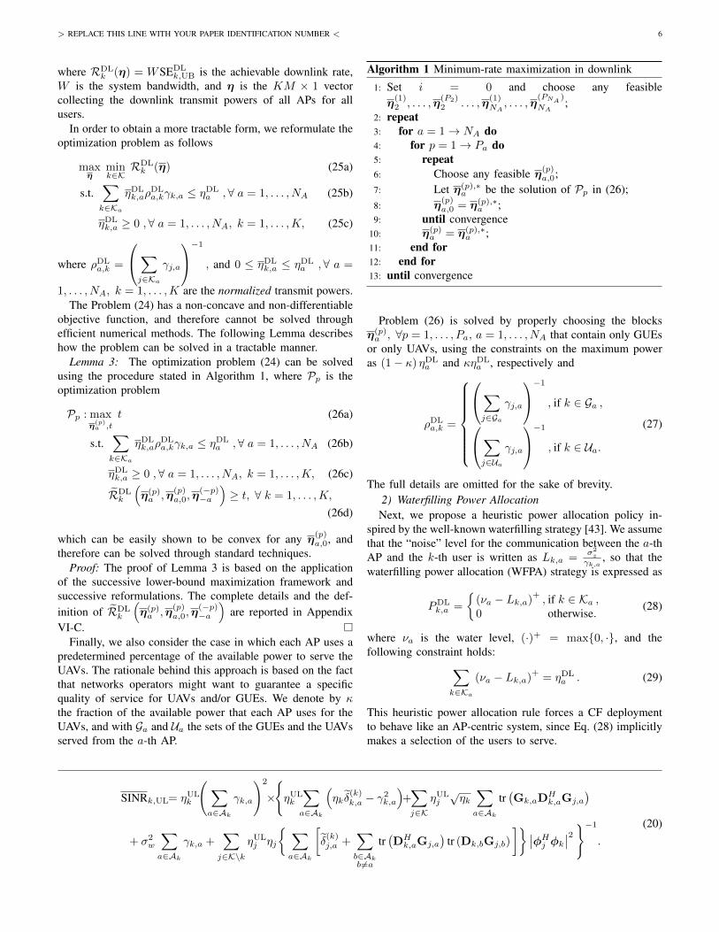
Fig. 7 includes the CDFs of the UL GUE rates for scenarioswith and without UAVs, and the same deployments consid-ered in Fig. 6. Interestingly, the results of Fig. 7 illustratethat—differently to what occurs in the baseline mMIMOdeployment—the introduction of UAVs in the network hasa negligible impact on the performance of both CF andUC architectures. This is because a) the UAV uplink pilotcontamination is adequately managed by the LMMSE channelestimator, and b) CF and UC architectures spread the serving
Figure 6: UL rates for UAVs under: (i) cell-free (CF), (ii) user-centric (UC) with Ak = 10, and (iii) multi-cell mMIMO (mMIMO)approaches.
APs in wider areas, which facilitates the spatial separationof the incoming—highly directional—UAV signals from thosetransmitted by GUEs. Consistently with the results obtainedin [27], [28], Fig. 7 also corroborates that GUEs can achievesimilar performances in CF and UC deployments.
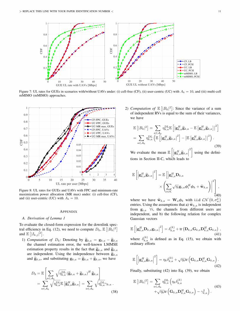
Finally, Fig. 8, is devoted to the performance assessmentof the power control rule maximizing the minimum ULrates. This figure reports the CDFs of the GUE and UAVUL LB rates in the UC and CF scenarios. Comparing theresults of UC-FPC with UC-MR max, we can observe thatthe 99%-likely per GUE rates UC deployment increase fromapproximately 0.94 Mbit/s (UC-FPC) to 1.5 Mbit/s (+ 60%),thus confirming the effectiveness of the proposed strategy forimproving the system fairness across users, and in reducingthe performance unbalance between GUEs and UAVs.
VI. CONCLUSIONS
This paper has investigated the use of CF and UC architec-tures for supporting wireless communications with UAVs. As-suming that the propagation channel between the users, eitherUAVs or GUEs, and the APs follows a Ricean distribution,closed form formulas for the achievable spectral efficiencyLB for uplink and downlink with LMMSE channel estimationhave been derived. Several power control rules have beenconsidered, including one maximizing the minimum-rate max-imizing power allocation strategy, based on sequential lowerbound maximization. Numerical results have show that CFand its low-complexity UC alternative may provide superiorperformance in the support of UAVs communications thantraditional multi-cell mMIMO deployments. Moreover, sinceUAVs generally enjoy better channel conditions than GUEs, itmay be desirable to constrain the share of power that the APsshould use to serve the former.
> REPLACE THIS LINE WITH YOUR PAPER IDENTIFICATION NUMBER < 11
0 10 20 30 40 50
GUE UL rate with UAVs [Mbps]
0
0.2
0.4
0.6
0.8
1
CD
F
0 10 20 30 40 50
GUE UL without UAVs [Mbps]
0
0.2
0.4
0.6
0.8
1
CD
F
CF, LB
CF, PCSI
UC, LB
UC, PCSI
mMIMO, LB
mMIMO, PCSI
Figure 7: UL rates for GUEs in scenarios with/without UAVs under: (i) cell-free (CF), (ii) user-centric (UC) with Ak = 10, and (iii) multi-cellmMIMO (mMIMO) approaches.
0 5 10 15 20 25 30 35 40
UL rate per user [Mbps]
0
0.1
0.2
0.3
0.4
0.5
0.6
0.7
0.8
0.9
1
CD
F
CF-FPC, GUEs
UC-FPC, GUEs
UC-MR max, GUEs
CF-FPC, UAVs
UC-FPC, UAVs
UC-MR max, UAVs
0 1 2 3 40
0.01
0.02
0.03
0.04
0.05
Figure 8: UL rates for GUEs and UAVs with FPC and minimum-ratemaximization power allocation (MR max) under: (i) cell-free (CF),and (ii) user-centric (UC) with Ak = 10.
APPENDIX
A. Derivation of Lemma 1
To evaluate the closed-form expression for the downlink spec-tral efficiency in Eq. (12), we need to compute Dk, E
[|Bk|2
]and E
[|Ik,j |2
].
1) Computation of Dk: Denoting by gk,a = gk,a − gk,athe channel estimation error, the well-known LMMSEestimation property results in the fact that gk,a and gk,aare independent. Using the independence between gk,aand gk,a, and substituting gk,a = gk,a + gk,a, we have
Dk = E
[∑a∈Ak
√ηDLk,a (gk,a + gk,a)
Hgk,a
]=∑a∈Ak
√ηDLk,aE
[gHk,agk,a
]=∑a∈Ak
√ηDLk,aγk,a .
(38)
2) Computation of E[|Bk|2
]: Since the variance of a sum
of independent RVs is equal to the sum of their variances,we have
E[|Bk|2
]=∑a∈Ak
ηDLk,aE
[∣∣gHk,agk,a − E[gHk,agk,a
]∣∣2]=∑a∈Ak
ηDLk,a
(E[∣∣gHk,agk,a∣∣2]− ∣∣E [gHk,agk,a]∣∣2) .
(39)
We evaluate the mean E[∣∣∣gHk,agk,a∣∣∣2] using the defini-
tions in Section II-C, which leads to
E[∣∣∣gHk,agk,a∣∣∣2]= E
[∣∣∣gHk,aDk,a
×
(∑i∈K
√ηigi,aφ
Hi φk + wk,a
)∣∣∣∣∣2 ,(40)
where we have wk,a = Waφk with i.i.d CN(0, σ2
w
)entries. Using the assumptions that a) wk,a is independentfrom gi,a ∀i, the channels from different users areindependent, and b) the following relation for complexGaussian vectors
E[∣∣gHk,aDk,agk,a
∣∣2] = δ(k)k,a + tr
(Dk,aGk,aD
Hk,aGk,a
),
(41)where δ
(k)k,a is defined as in Eq. (15), we obtain with
ordinary efforts
E[∣∣∣gHk,agk,a∣∣∣2] = ηkδ
(k)k,a +
√ηktr
(Gk,aD
Hk,aGk,a
).
(42)Finally, substituting (42) into Eq. (39), we obtain
E[|Bk|2
]=∑a∈Ak
ηDLk,a
(ηkδ
(k)k,a
+√ηktr
(Gk,aD
Hk,aGk,a
)− γ2k,a
).
(43)
> REPLACE THIS LINE WITH YOUR PAPER IDENTIFICATION NUMBER < 12
3) Computation of E[|Ik,j |2
]: Using a similar approach as
in Eq. (39) we obtain
E[|Ik,j |2
]= ηkE
∣∣∣∣∣∣∑a∈Aj
√ηDLj,a g
Hk,aDj,agk,a
∣∣∣∣∣∣2 ∣∣φHk φj
∣∣2+∑a∈Aj
∑i∈K\k
ηDLj,a ηitr
(Dj,aGi,aD
Hj,aGk,a
) ∣∣φHi φj∣∣2
+σ2w
∑a∈Aj
ηDLj,a tr
(Dj,aD
Hj,aGk,a
).
(44)The expectation that appears in Eq. (44) can be computed,using a similar approach as in Eq. (42), as
E
∣∣∣∣∣∣∑a∈Aj
√ηDLj,a g
Hk,aDj,agk,a
∣∣∣∣∣∣2
=∑a∈Aj
ηDLj,a
(δ(j)k,a + tr
(Dj,aGk,aD
Hj,aGk,a
))+∑a∈Aj
∑b∈Ajb6=a
√ηDLj,a
√ηDLj,b tr (Dj,aGk,a) tr
(DHj,bGk,b
).
(45)Substituting Eq. (45) into Eq. (44), and using the defini-tions in Section II-C we obtain
E[|Ik,j |2
]=∑a∈Aj
ηDLj,a√ηj tr
(Gj,aD
Hj,aGk,a
)+ηk
∣∣φHk φj∣∣2 ∑a∈Aj
[ηDLj,a δ
(j)k,a
+∑b∈Ajb6=a
√ηDLj,a
√ηDLj,b tr (Dj,aGk,a) tr
(DHj,bGk,b
) .
(46)Finally, the downlink spectral efficiency LB in Eq. (14)can be derived by plugging Eqs. (38), (43) and (46) intoEq. (12).
B. Derivation of Lemma 2
The derivation of (21) is similar to the one of (14).1) Computation of Dk: Using a similar procedure as in the
downlink we have:
Dk =√ηULk
∑a∈Ak
γk,a . (47)
2) Computation of E[∣∣∣Bk∣∣∣2]: Following a similar approach
as in Eqs. (43), we obtain
E[|Bk|2
]= ηUL
k
∑a∈Ak
(ηk δ
(k)k,a
+√ηktr
(Gk,aD
Hk,aGk,a
)− γ2k,a
),
(48)
where δ(k)k,a is defined as in Eq. (22).
3) Computation of E[∣∣∣Nk∣∣∣2]: Since the RVs representing
the noise and the wireless channel are independent, andconsidering that the variance of a sum of independentRVs is equal to the sum of the variances, we have
E[∣∣∣Nk∣∣∣2] = σ2
w
∑a∈Ak
γk,a . (49)
4) Computation of E[∣∣∣Ik,j∣∣∣2]: Using a similar approach as
in Eq. (46), we obtain:
E[|Ik,j |2
]= ηUL
j
∑a∈Ak
√ηktr
(DHk,aGj,aGk,a
)+ηjη
ULj
∑a∈Ak
[δ(k)j,a
+∑b∈Akb6=a
tr(DHk,aGj,a
)tr (Dk,bGj,b)
∣∣φHj φk∣∣2 .
(50)
Finally, the uplink spectral efficiency LB in Eq. (21) canbe derived by plugging Eqs. (47), (48), (49), and (50) inEq. (19).
C. Derivation of Lemma 3
To circumvent the challenge of non-differentiability of theProblem (24), we reformulate it as
maxη,t
t (51a)
s.t.∑k∈Ka
ηDLk,aρ
DLa,kγk,a ≤ ηDL
a ,∀ a = 1, . . . , NA (51b)
ηDLk,a ≥ 0 ,∀ a = 1, . . . , NA, k = 1, . . . ,K, (51c)
RDLk (η) ≥ t, ∀ k = 1, . . . ,K. (51d)
To solve (51), following an approach similar to that in[33], the framework of successive lower-bound maximization[32], which combines the tools of alternating optimization[48, Section 2.7] and sequential convex programming [49]can be used. In particular, consider Problem (51) and definethe L-dimensional variable blocks η(p)
a , a = 1, . . . , NA, p =1, . . . , Pa, collecting the p-th block of “normalized” transmitpowers of the a-th AP. Then, the minimum-rate maximizationproblem can be reformulated as
maxη
(p)a ,t
t (52a)
s.t.∑k∈Ka
ηDLk,aρ
DLa,kγk,a ≤ ηDL
a ,∀ a = 1, . . . , NA (52b)
ηDLk,a ≥ 0 ,∀ a = 1, . . . , NA, k = 1, . . . ,K. (52c)
RDLk (η(p)
a ,η(−p)−a ) ≥ t, ∀ k = 1, . . . ,K. (52d)
Although (52) is still non-convex, its complexity is signif-icantly lower than that of (51), since only the block of Ltransmit powers of the a-th AP are being optimized. Notice
> REPLACE THIS LINE WITH YOUR PAPER IDENTIFICATION NUMBER < 13
that the k-th user’s downlink achievable rate can be written as
RDLk (η) = W
τdτc
log2 [g1 (η) + g2 (η)]−W τdτc
log2 [g2 (η)] ,
(53)where g1 (η) and g2 (η) are defined as
g1 (η) =
(∑a∈Ak
√ηDLk,aρ
DLa,kγk,a
)2
,
g2 (η) =∑j∈K
√ηj∑a∈Aj
ηDLj,aρ
DLa,ktr
(Gj,aD
Hj,aGk,a
)+ σ2
z
+∑j∈K\k
ηk∣∣φHk φj
∣∣2∑a∈Aj
[ηDLj,aρ
DLa,kδ
(j)k,a
+∑b∈Ajb 6=a
√ηDLj,aρ
DLa,k
√ηDLj,b ρ
DLb tr (Dj,aGk,a) tr
(DHj,bGk,b
) .
(54)Since the function in Eq. (53) is non-concave, even withrespect to only the variable block η(p)
a , optimization (52)will be tackled by sequential optimization. To this end, weneed a lower-bound of RDL
k (η), which fulfills properties in[49], while at the same time leading to a simple optimizationproblem. Using the fact that the function f(x, y) =
√xy
is jointly concave in x and y, for x, y > 0, and since thefunction log2(·) is an increasing function, and summationpreserves concavity, the rate function in (53) is the differenceof two concave functions [33], [34]. Recalling that any concavefunction is upper-bounded by its Taylor expansion aroundany given point η
(p)a,0, a concave lower-bound of RDL
k (η) isobtained as
RDLk
(η(p)a
)≥ RDL
k
(η(p)a
)=
Wτdτc
log2
[g1
(η(p)a
)+ g2
(η(p)a
)]−W τd
τclog2
[g2
(η(p)a,0
)]−W τd
τc∇T
η(p)a
log2
[g2|η(p)
a,0
(η(p)a
)] (η(p)a − η
(p)a,0
).
(55)Relying on this bound, we can solve Problem (52) through thesequential optimization method, by defining the p-th problemof the sequence, Pp, as the convex optimization problemin (26). Following the successive lower-bound maximizationframework, it thus follows that the original optimization prob-lem (24) can be solved using the procedure in Algorithm 1.
REFERENCES
[1] G. Geraci, A. Garcia-Rodriguez, and X. Lin, “Preparing the ground fordrone communications,” in IEEE ComSoc Technology News, Jun. 2019.
[2] M. Mozaffari, W. Saad, M. Bennis, Y. Nam, and M. Debbah, “A tutorialon UAVs for wireless networks: Applications, challenges, and openproblems,” IEEE Communications Surveys Tutorials, pp. 1–1, Mar. 2019.
[3] M. Mozaffari, W. Saad, M. Bennis, and M. Debbah, “Unmanned aerialvehicle with underlaid device-to-device communications: Performanceand tradeoffs,” IEEE Transactions on Wireless Communications, vol. 15,no. 6, pp. 3949–3963, Jun. 2016.
[4] S. Hayat, E. Yanmaz, and R. Muzaffar, “Survey on unmanned aerialvehicle networks for civil applications: A communications viewpoint,”IEEE Communications Surveys Tutorials, vol. 18, no. 4, pp. 2624–2661,Apr. 2016.
[5] J. Wang, C. Jiang, Z. Han, Y. Ren, R. G. Maunder, and L. Hanzo,“Taking drones to the next level: Cooperative distributed unmanned-aerial-vehicular networks for small and mini drones,” IEEE VehicularTechnology Magazine, vol. 12, no. 3, pp. 73–82, Sep. 2017.
[6] A. Fotouhi, H. Qiang, M. Ding, M. Hassan, L. G. Giordano, A. Garcia-Rodriguez, and J. Yuan, “Survey on UAV cellular communications:Practical aspects, standardization advancements, regulation, and securitychallenges,” IEEE Communications Surveys Tutorials, vol. PP, pp. 1–1,Mar. 2019.
[7] E. Vinogradov, H. Sallouha, S. De Bast, M. M. Azari, and S. Pollin,“Tutorial on UAV: A blue sky view on wireless communication,” arXivpreprint arXiv:1901.02306, Jan. 2019.
[8] A. Merwaday and I. Guvenc, “UAV assisted heterogeneous networks forpublic safety communications,” in 2015 IEEE wireless communicationsand networking conference workshops (WCNCW), Mar. 2015, pp. 329–334.
[9] J. Lyu, Y. Zeng, R. Zhang, and T. J. Lim, “Placement optimizationof UAV-mounted mobile base stations,” IEEE Communications Letters,vol. 21, no. 3, pp. 604–607, Mar. 2017.
[10] M. Mozaffari, W. Saad, M. Bennis, and M. Debbah, “Efficient de-ployment of multiple unmanned aerial vehicles for optimal wirelesscoverage,” IEEE Communications Letters, vol. 20, no. 8, pp. 1647–1650,Aug. 2016.
[11] R. I. Bor-Yaliniz, A. El-Keyi, and H. Yanikomeroglu, “Efficient 3-Dplacement of an aerial base station in next generation cellular networks,”in 2016 IEEE International Conference on Communications (ICC), May2016, pp. 1–5.
[12] X. Lin, V. Yajnanarayana, S. D. Muruganathan, S. Gao, H. Asplund,H. L. Maattanen, M. Bergström, S. Euler, and Y.-P. E. Wang, “The skyis not the limit: LTE for unmanned aerial vehicles,” IEEE Commun.Mag., vol. 56, no. 4, pp. 204–210, Apr. 2018.
[13] M. M. Azari, F. Rosas, and S. Pollin, “Reshaping cellular networks forthe sky: The major factors and feasibility,” in Proc. IEEE ICC, May2018, pp. 1–7.
[14] Y. Zeng, J. Lyu, and R. Zhang, “Cellular-connected UAV: Potential,challenges, and promising technologies,” IEEE Wireless Communica-tions, vol. 26, no. 1, pp. 120–127, Feb. 2019.
[15] D. López-Pérez, M. Ding, H. Li, L. Galati Giordano, G. Geraci,A. Garcia-Rodriguez, Z. Lin, and M. Hassan, “On the downlink per-formance of UAV communications in dense cellular networks,” in Proc.IEEE Globecom, Dec. 2018, pp. 1–7.
[16] M. M. Azari, G. Geraci, A. Garcia-Rodriguez, and S. Pollin, “CellularUAV-to-UAV communications,” in 2019 IEEE 30th Annual InternationalSymposium on Personal, Indoor and Mobile Radio Communications(PIMRC), Sep. 2019, available as arXiv:1904.05104.
[17] W. Mei, Q. Wu, and R. Zhang, “Cellular-connected uav: Uplink associ-ation, power control and interference coordination,” IEEE Transactionson Wireless Communications, vol. 18, no. 11, pp. 5380–5393, Nov. 2019.
[18] A. Garcia Rodriguez, G. Geraci, D. López-Pérez, L. Galati Giordano,M. Ding, and E. Björnson, “The essential guide to realizing 5G-connected UAVs with massive MIMO,” IEEE Communications Mag-azine, pp. 2–8, Oct. 2019.
[19] G. Geraci, A. Garcia-Rodriguez, L. Galati Giordano, D. López-Pérez,and E. Björnson, “Understanding UAV cellular communications: Fromexisting networks to massive MIMO,” IEEE Access, vol. 6, Nov. 2018.
[20] G. Geraci, A. Garcia-Rodriguez, L. Galati Giordano, D. López-Pérez,and E. Björnson, “Supporting UAV cellular communications throughmassive MIMO,” in Proc. IEEE ICC Workshops, May 2018, pp. 1–6.
[21] P. Chandhar, D. Danev, and E. G. Larsson, “Massive MIMO forcommunications with drone swarms,” IEEE Transactions on WirelessCommunications, vol. 17, no. 3, pp. 1604–1629, Mar. 2018.
[22] R. Amer, W. Saad, and N. Marchetti, “Toward a connected sky:Performance of beamforming with down-tilted antennas for ground andUAV user co-existence,” IEEE Communications Letters, vol. 23, no. 10,pp. 1840–1844, Oct. 2019.
[23] J. Lyu and R. Zhang, “Network-connected UAV: 3-D system modelingand coverage performance analysis,” IEEE Internet of Things Journal,vol. 6, no. 4, pp. 7048–7060, Aug. 2019.
[24] H. Q. Ngo, A. Ashikhmin, H. Yang, E. G. Larsson, and T. L. Marzetta,“Cell-free massive MIMO versus small cells,” IEEE Trans. WirelessCommun., vol. 16, no. 3, pp. 1834–1850, Jan. 2017.
[25] P. Frenger, J. Hederen, M. Hessler, and G. Interdonato, “Improvedantenna arrangement for distributed massive MIMO,” WO patent ap-plication 2018103897, 2017.
[26] G. Interdonato, E. Björnson, H. Q. Ngo, P. Frenger, and E. G. Lars-son, “Ubiquitous cell-free massive MIMO communications,” EURASIP
> REPLACE THIS LINE WITH YOUR PAPER IDENTIFICATION NUMBER < 14
Journal on Wireless Communications and Networking, vol. 2019, no. 1,p. 197, Aug. 2019.
[27] S. Buzzi and C. D’Andrea, “Cell-free massive MIMO: User-centricapproach,” IEEE Wireless Commun. Letters, vol. 6, no. 6, pp. 706–709,Dec. 2017.
[28] S. Buzzi and C. D’Andrea, “User-centric communications versus cell-free massive MIMO for 5G cellular networks,” in Proc. Int. ITGWorkshop on Smart Antennas, Mar. 2017, pp. 1–6.
[29] S. Buzzi, C. D’Andrea, A. Zappone, and C. D’Elia, “User-centric5G cellular networks: Resource allocation and comparison with thecell-free massive MIMO approach,” IEEE Transactions on WirelessCommunications, pp. 1–1, Nov. 2019.
[30] G. Interdonato, P. Frenger, and E. G. Larsson, “Scalability aspects ofcell-free massive MIMO,” in ICC 2019 - 2019 IEEE InternationalConference on Communications (ICC), May 2019, pp. 1–6.
[31] C. D’Andrea, A. Garcia-Rodriguez, G. Geraci, L. G. Giordano, andS. Buzzi, “Cell-free massive MIMO for UAV communications,” in 2019IEEE International Conference on Communications Workshops (ICCWorkshops), May 2019, pp. 1–6.
[32] M. Razaviyayn, M. Hong, and Z.-Q. Luo, “A unified convergenceanalysis of block successive minimization methods for nonsmoothoptimization,” SIAM Journal on Optimization, vol. 23, no. 2, Jun. 2013.
[33] S. Buzzi and A. Zappone, “Downlink power control in user-centricand cell-free massive MIMO wireless networks,” in 2017 IEEE 28thAnnual International Symposium on Personal, Indoor, and Mobile RadioCommunications (PIMRC), Oct. 2017, pp. 1–6.
[34] M. Alonzo, S. Buzzi, and A. Zappone, “Energy-efficient downlink powercontrol in mmwave cell-free and user-centric massive MIMO,” in 2018IEEE 5G World Forum (5GWF), Jul. 2018, pp. 493–496.
[35] M. Bashar, K. Cumanan, A. G. Burr, H. Q. Ngo, and M. Debbah, “Cell-free massive MIMO with limited backhaul,” in 2018 IEEE InternationalConference on Communications (ICC), May 2018, pp. 1–7.
[36] M. Bashar, K. Cumanan, A. G. Burr, H. Q. Ngo, M. Debbah, andP. Xiao, “Max–min rate of cell-free massive MIMO uplink with optimaluniform quantization,” IEEE Transactions on Communications, vol. 67,no. 10, pp. 6796–6815, Oct. 2019.
[37] H. Q. Ngo, A. Ashikhmin, H. Yang, E. G. Larsson, and T. L. Marzetta,“Cell-free massive MIMO: Uniformly great service for everyone,” in2015 IEEE 16th International Workshop on Signal Processing Advancesin Wireless Communications (SPAWC). IEEE, Jul. 2015, pp. 201–205.
[38] A. H. Jafari, D. López-Pérez, M. Ding, and J. Zhang, “Study onscheduling techniques for ultra dense small cell networks,” in Proc. IEEEVTC-Fall, Sept. 2015, pp. 1–6.
[39] Ö. Özdogan, E. Björnson, and J. Zhang, “Cell-free massive MIMO withRician fading: Estimation schemes and spectral efficiency,” in 2018 52ndAsilomar Conference on Signals, Systems, and Computers, Oct. 2018,pp. 975–979.
[40] H. Q. Ngo, H. Tataria, M. Matthaiou, S. Jin, and E. G. Larsson, “Onthe performance of cell-free massive MIMO in ricean fading,” in 201852nd Asilomar Conference on Signals, Systems, and Computers, Oct.2018, pp. 980–984.
[41] T. L. Marzetta, E. G. Larsson, H. Yang, and H. Q. Ngo, Fundamentalsof massive MIMO. Cambridge University Press, 2016.
[42] G. Caire, “On the ergodic rate lower bounds with applications to massiveMIMO,” IEEE Trans. Wireless Commun., vol. 17, no. 5, pp. 3258–3268,May 2018.
[43] T. M. Cover and J. A. Thomas, Elements of Information Theory. JohnWiley & Sons, 2006.
[44] P. Baracca, L. Galati Giordano, A. Garcia-Rodriguez, G. Geraci, andD. López-Pérez, “Downlink performance of uplink fractional powercontrol in 5G massive MIMO systems,” in Proc. IEEE Globecom, Dec.2018, pp. 1–7.
[45] 3GPP, “Technical specification group radio access network; study onenhanced LTE support for aerial vehicles,” 3GPP TR 36.777, Tech. Rep.,Dec. 2017.
[46] 3GPP, “Further advancements for E-UTRA physical layer aspects (Re-lease 9),” 3GPP TS 36.814, Tech. Rep., Mar. 2017.
[47] E. Björnson and L. Sanguinetti, “Making cell-free massive MIMOcompetitive with MMSE processing and centralized implementation,”arXiv preprint arXiv:1903.10611, Mar. 2019.
[48] D. P. Bertsekas, Nonlinear Programming. Athena Scientific, 1999.[49] B. R. Marks and G. P. Wright, “A general inner approximation algorithm
for non-convex mathematical programs,” Operations Research, vol. 26,no. 4, pp. 681–683, Aug. 1978.
Carmen D’Andrea (S’18 - M’20) was born in Caserta, Italy on 16 July1991. She received the B.S. and M.S. degrees, both with honors, in Telecom-munications Engineering from University of Cassino and Lazio Meridionalein 2013 and 2015, respectively. In 2017, she was a Visiting Ph.D. student withthe Wireless Communications (WiCom) Research Group in the Department ofInformation and Communication Technologies at Universitat Pompeu Fabra inBarcelona, Spain. In 2019, she received the Ph.D. degree with highest marks inElectrical and Information Engineering from University of Cassino and LazioMeridionale. She is currently a Post-Doctoral Researcher with Departmentof Electrical and Information Engineering, University of Cassino and LazioMeridionale. Her research interests are focused on wireless communicationand signal processing, with a current emphasis on mmWave communicationsand massive MIMO systems, in both colocated and distributed setups.
Adrian Garcia-Rodriguez is a Research Scientist in Nokia Bell Labs(Ireland), where he focuses on the design of UAV communications and next-generation 802.11 technologies. He joined Bell Labs in 2016, after receivingthe Ph.D. degree in Electrical and Electronic Engineering from UniversityCollege London (U.K.). Adrian is a co-inventor of fifteen filed patent familiesand co-author of 40+ IEEE publications. He was the recipient of the BestPaper Award in PIMRC’19 and was named an Exemplary Reviewer for IEEECommun. Letters in 2016, and both IEEE Trans. on Wireless Commun. andIEEE Trans. on Commun. in 2017.
Giovanni Geraci is an Assistant Professor and Junior Leader Fellow at UPFBarcelona (Spain). He earned a Ph.D. from the UNSW Sydney (Australia)in 2014, and was a Research Scientist with Nokia Bell Labs (Ireland) in2016-2018. His background also features research appointments at SUTD(Singapore) in 2014-2015, UT Austin (USA) in 2013, CentraleSupélec(France) in 2012, and Alcatel-Lucent (Italy) in 2009. He has been servingas an Editor for the IEEE Transactions on Wireless Communications andIEEE Communications Letters, and as a workshop co-chair at IEEE ICC,IEEE Globecom, and Asilomar. He has been a panelist, workshop keynote,and industrial seminar or tutorial speaker at IEEE ICC, IEEE Globecom,IEEE WCNC, IEEE PIMRC, and IEEE VTC Spring. He has co-authored 50+IEEE publications with 1500+ citations, and is co-inventor of a dozen filedpatent families. Giovanni was the recipient of the Best Paper Award at IEEEPIMRC’19 and of the IEEE ComSoc Outstanding Young Researcher Awardfor Europe, Middle-East & Africa 2018.
Lorenzo Galati Giordano (M’15) is Member of Technical Staff at NokiaBell Labs Ireland since 2015. Lorenzo received the M.Sc. and the Ph.D.degrees in wireless communication from Politecnico di Milano, Italy, in 2005and 2010, respectively, and the master’s degree in Innovation Managementfrom IlSole24Ore Business School, Italy, in 2014. He was also Marie-CurieShort Term Fellow at University of Bedfordshire (UK) in 2008, researcherassociate with the Italian National Research Council in 2010 and R&DEngineer for Azcom Technology, an Italian SME, from 2010 to 2014. Lorenzohas more than 10 years of academical and industrial research experience onwireless communication systems and protocols, holds commercial patents andpublications in prestigious IEEE journals and conferences. During the pastyears, Lorenzo contributed to the Nokia F-Cell project, an innovative self-powered and auto-connected drone deployed small cell served by massiveMIMO wireless backhaul, which received the CTIA Emerging Technology2016 Award. Lorenzo’s current focus is on future indoor networks and nextgeneration Wi-Fi technologies, an area where he is contributing with largeantenna arrays solutions for the unlicensed spectrum.
Stefano Buzzi (M’98-SM’07) is Full Professor at the University of Cassinoand Lazio Meridionale, Italy. He received the M.Sc. degree (summa cumlaude) in Electronic Engineering in 1994, and the Ph.D. degree in Electricaland Computer Engineering in 1999, both from the University of Naples“Federico II”. He has had short-term research appointments at PrincetonUniversity, Princeton (NJ), USA in 1999, 2000, 2001 and 2006. He is aformer Associate Editor of the IEEE Signal Processing Letters and of the IEEECommunications Letters, has been the lead guest editor of three IEEE JSACspecial issues (June 2014, April 2016, and April 2019), while is currentlyserving as an Editor for the IEEE Transactions on Wireless Communications.He is also a Member of the IEEE Future Networks Editorial Board, andserves regularly as TPC member of several international conferences. Dr.Buzzi’s research interests are in the broad field of communications and signalprocessing, with emphasis on wireless communications. He has co-authoredabout 160 technical peer-reviewed journal and conference papers, and amongthese, the highly-cited survey paper “What will 5G be?” (IEEE JSAC, June2014) on 5G wireless networks.


![A Review of Network Mobility Protocols For Fully ... · > REPLACE THIS LINE WITH YOUR PAPER IDENTIFICATION NUMBER (DOUBLE-CLICK HERE TO EDIT) < 2 [12]. Compared to MIPv6/NEMO,](https://static.documents.pub/doc/80x56/5d0b44a788c993a3148b5c94/a-review-of-network-mobility-protocols-for-fully-replace-this-line-with.jpg)


