Replacement of Chain guides on M62 / M62tu Remove battery terminal. Remove engine covers, cabin air filter housings. remove mass air sensor, and remove upper covers on valve covers, and remove coils.
Transcript
Replacement of Chain guides on M62 / M62tu
Remove battery terminal.
Remove engine covers, cabin air filter housings. remove mass air sensor, and remove upper covers on valve
covers, and remove coils.
Unplug engine wiring harness from engine.
Remove fuel injector wiring housing on each side. Remove 10 mm nut (2 each side). Grab housing on both
ends, and pull sharply to unclip from injectors.
Remove fan, fan shroud, and expansion tank. Jack up car slightly to clear drain pan. Pull plug from bottom of
radiator, and drain coolant.
Remove belt tensioners. Remove terminal from alternator, and remove alternator. Keep drain pan under
alternator, a lot of coolant will come out, (do not skip this step, you will get water in oil pan if you don’t).
Remove radiator, Egr pipe, and water pump. Remove crank pulley. Bolt special tool onto crank hub with a
minimum of 3 bolts. Place a piece of wood in between passenger side of frame, and handle of special tool. Use
large breaker bar and 1 1/16 socket to loosen crank bolt. The bolt is very tight, (300 ft pounds of torque). I
used a ¾ breaker bar and socket, as I broke the ½ bar.
Remove special tool, but leave bolt in crank for now.
Jack up car, and place on jack stands. Only place jack stands on frame of car. You will need enough room to get
under the car to remove lower oil pan. As a general practice, I always leave the jack under the car, that way if a
jack stand should slip off, the jack just may support the weight long enough for me to get out and clean my
shorts.
Temporarily re install crank pulley to align the 0 mark on stamped on crank pulley with the arrow on timing
cover. Use 1 1/16 socket and ratchet to rotate crank. Under car, you will need to use crank lock pin, and insert
it into the locating hole in the bellhousing area on the bottom rear of the engine. Rotate the engine a little bit
until the pin goes into the hole on the flywheel. The pin should go all the way to the face of the engine. Double
check by trying to turn the crank by hand. It should not turn.
Remove both valve covers, and front upper timing cover
Remove power steering pump. Note knurled adjustment nut. Do not turn it, leave it where it is!
Jeff
Oval
Jeff
Sticky Note
Do not turn this knurled nut! leave it where it was originally, will affect belt alignment, may crack pump housing maybe.
Drain the oil, and Remove lower oil pan. There are many bolts. I broke them loose with a ratchet, then used a
drill with a socket to remove the rest. Check out pan for pieces of guides. Note: if yo find no pieces, it does not
necessarily mean that the guides are good. This engine had 78k miles on it, and the guides appeared to be
good with no parts in the pan. But, when I pulled off the chain, pieces of the guides were falling off. The chain
was holding the pieces of the guides in place!
When looking up into the engine from under it, there are about 5 bolts in the front of the engine that go into
the lower timing cover, they will need to be removed, and there is also one on the side of the engine block.
Remove all bolts from the lower front timing cover, do not forget the one in the water pump gallery. Pull lower
timing cover off. It should come off somewhat easy, if it doesn’t, check for additional bolts.
Remove timing chain guides, starting with tensioner side, then deflection rail. Remove last guide, and finally
chain.
Remove oil separator. They are usually brittle, and break while removing the guides. Also, the hose to it
usually breaks down into little pieces. Plan on replacing it.
Cover oil pan area with rag, and use a razor to scrape and clean gasket surfaces.
Install new oil separator. Install new guides and chain. It will be tight getting it on.
Jeff
Sticky Note
the oil separator usually breaks down at this plastic hose. it will probrably fall apart when you remove timing guides.
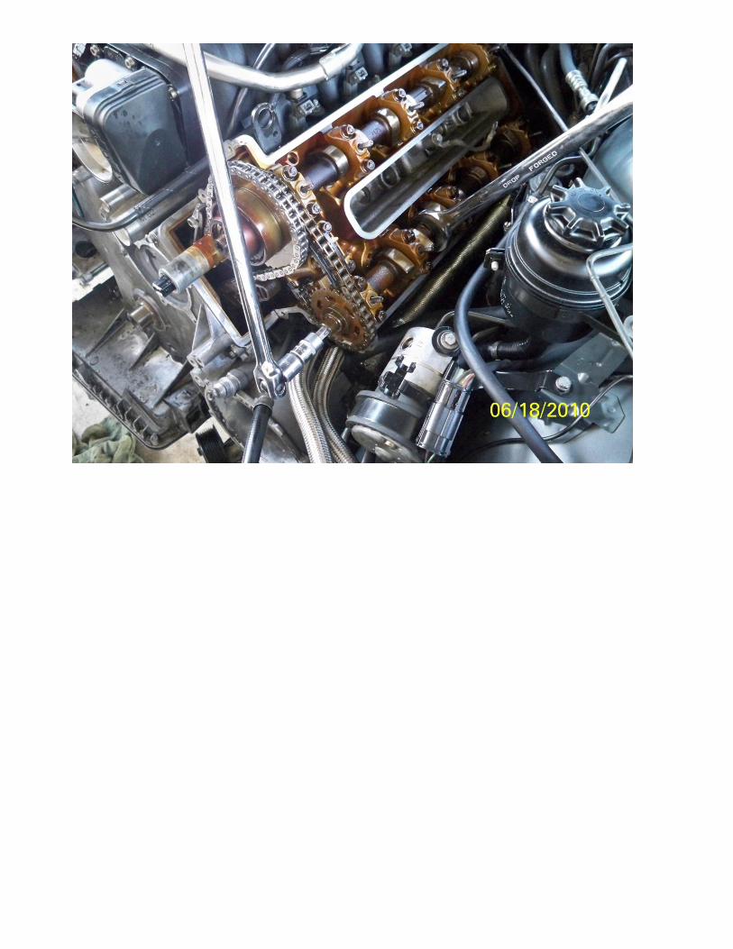
Wipe clean gasket surfaces, and apply silicone to oil pan gasket area (note green gasket on above photo). put
steel coated gaskets in place, on water pump area and sides of timing cover. Place a small dab of silicone in
corner of oil pan and block. Install lower timing cover. Be sure to remember to put bolts in bottom of cover
through oil pan opening back.
Replace oil pan gasket, and reinstall lower oil pan. (leave car on jacks still!)
Remove oil tubes (flat tubes on top of cams).
Hold the cam with the wrench, and move wrench until wrench handle contacts head surface or body to keep
wrench from turning. If you turn cam, and the cam stops, turn the cam the opposite direction, as a valve must
be contacting a piston. You can bend a valve if you put too much force on it. Use socket to remove sensor
wheel disks. The nut is left handed.
Use t-55 torx bit and 1 1/16 wrench to break loose cam bolts. Tap them around the sides of the bolt heads
before wrenching on them to break them loose. I broke off about 70 worth of breaker bars and torx bits until I
figured this out. Break bolts loose. They are left handed, and about 115 ft lbs of torque on them.
On the rear of each camshaft there is a machined square. 2 sides are precision ground, and 2 sides are left as
cast. One of the cast sides have numbers stamped into them. After loosening all 4 cam bolts, use wrench to
rotate cams until the side with the stampings are facing up away from the face of the head. Once again, If you
turn the cam, and the cam stops, turn the cam the opposite direction, as a valve must be contacting a piston.
You can bend a valve if you put too much force on it.
Jeff
Oval
Jeff
Sticky Note
Note stamping on each cam! must turn cams so this side faces away from head.
Get special tooling blocks. One side is for the passengers side, and the other is for the drivers side. They are
numbered by the bank they go on, the passenger is 1-4, and drivers side is 5-8. The cams are also stamped with
these numbers. Use wrench to wiggle cams gently into the fixture on both cams, on both sides of the engine.
The stamped side of the cam must face the numbered side of the fixture block. As you can see from the
picture below, the cams are not straight up in relation to the head, and as you will find out shortly, the cams
are not located by any other means, and are infinitely adjustable. Best of luck to the guys who are going to
attempt it without the special tools.
Jeff
Sticky Note
Take note of the markings on the face of the tooling. these markings will match the stampings on the camshaft locating squares.
Jeff
Oval
Jeff
Sticky Note
Note that the cam markings are facing up in fixture.
Tap on the top of the fixture blocks with the wooden handle of a hammer, or dead blow mallet to seat blocks
against head surface.
On m62tu, use volt meter to verify van os adjuster is at left stop by placing ohm meter across terminal on vanos
sprocket, and chain, or other ground. When at left stop, the terminal will ground out. Non vanos engines do
not have this step.
Use torque wrench with special socket and turn vanos adjuster ccw to left stop at 40nm on each bank.
Install tensioner adjuster and bracket. Hand tighten adjuster for now.
Tighten 4 sprocket bolts with t-55 torx bit to 15nm, and back off ¼ turn. Use special torque tool and tighten
tensioner to 6 inch pounds (.7nm).
Jeff
Sticky Note
torque to 6 inch pounds, or .7 nm.
Once again, use the torque wrench and turn the vanos adjuster 40 nm to left stop. It may move when taking
the slack out of the chain.
Use t-55 torx bit and 1 1/16 wrench to Tighten vanos and exhaust bolts to spec. Do not remove cam fixtures
yet!
Jeff
Sticky Note
exhaust bolts get tightened to 125 nm, intake (vanos) bolts get tightened to 110 nm.
Get cam sensor wheel fixtures. Place sensor disks on cams, and place fixtures at top of each head surface and
bolt them down. Tap top of fixture to be sure that it is seated against top of head. Align dowel in fixture with
dowel hole in disk. Push dowel into disk, and tighten set screw securing dowel pin. Tighten sensor disk wheel
to spec.
Jeff
Sticky Note
sensor disk nuts get tightened to 40 nm.
Remove tensioner block, and cam sensor disk fixtures.
Re-install upper timing covers. Place a little oil into new chain tensioner, and install tensioner into cover. it will
probably be hard to get the thread to start, because there is less slack in the timing chain now. After installing
tensioner, remove cam fixtures, and crank lock pin from under car. Re-assemble vehicle.