Master’s Thesis in Computer Science at Stockholm University, Sweden 2008 Replication Technology and Failover Solution Development for the MySQL Open Source Database Management System Elena Malioutina
Transcript
Master’s Thesis in Computer Science at Stockholm University, Sweden 2008
Replication Technology and Failover Solution Development for the MySQL Open Source Database Management System
Elena Malioutina
Replication Technology and Failover Solution Development for the MySQL Open Source Database Management System
Elena Malioutina
Master’s Thesis in Computer Science (30 ECTS credits) First Degree Programme in Mathematics and Computer Science Stockholm University year 2008 Supervisor at Nada was Kjell Lindqvist Examiner was Stefan Arnborg TRITA-CSC-E 2008:081 ISRN-KTH/CSC/E--08/081--SE ISSN-1653-5715 Department of Numerical Analysis and Computer Science Royal Institute of Technology SE-100 44 Stockholm, Sweden
Abstract
The goal of this thesis work is to develop a failover solution for MySQL open source database management system to provide automatic failover as a future feature. It is also to analyse replication technology, i.e. different replication techniques and protocols, failover and replication solutions for the main database management systems.
One of the replication configurations offered by the MySQL database management system is a single master with slaves. This report describes how to find the current position for each of the slaves in the new master’s binary log during failover in the event of master failure.
Sammanfattning
Replikeringsteknologi och utveckling av en lösning till fail-over-problemet för databashanteraren MySQL
Ett mål med detta examensarbete är att utveckla en lösning till fail-over-problemet för databashanteraren MySQL, dvs. att utveckla en lösning för att kunna genomföra skiftet av master i ett system med en master och slavar när master fallerar. Ett annat mål är att analysera replikeringsteknologi, dvs. olika replikeringstekniker och protokoll, fail-over-problemet och replikeringslösningar för de ledande databashanterarna.
En av de replikeringskonfigurationer som databashanteraren MySQL erbjuder är en master med slavar. Rapporten beskriver hur den aktuella positionen för varje slav i den nya masters binära log kan lokaliseras under masterskiftet i den händelse att master-fel uppstår.
3.1 Configurations ................................................................................................ 13 3.1.1 Master with Slaves .............................................................................. 13 3.1.3 Dual Master ......................................................................................... 13 3.1.4 Master Ring ......................................................................................... 14 3.2 How MySQL Replication Works ................................................................... 16 3.3 Propagation Mechanism ................................................................................. 16
4 High Availability and Failover ............................................................................... 17
4.1 Failover in the MySQL DBMS ...................................................................... 17 4.2 Finding the Current Position in the New Master’s Log ................................ 19
5.1 Introduction of Global Transaction ID ........................................................... 22 5.2 Introduction of transaction_info Table .......................................................... 25 5.3 Failover with the New Features ..................................................................... 28 5.4 Failover Algorithm ......................................................................................... 29 5.5 Switching Back to the Original Master .......................................................... 31 5.6 Implementation of Failover Algorithm .......................................................... 32
6.1 Work Performed ............................................................................................. 33 6.2 Future Features ............................................................................................... 34 6.3 Other Areas of Use ......................................................................................... 35
Abbreviations ................................................................................................................. 36 References ...................................................................................................................... 37 Appendix A: Code ......................................................................................................... 39 Appendix B: Description of the Replication Techniques Used in the Main Database Management Systems .................................................................................................... 43
Acknowledgments
I would like to take the opportunity to thank my supervisor at KTH Kjell Lindqvist for all help and support during the work. At MySQL AB I would like to thank my supervisor Lars Thalmann and also Mats Kindahl for all their help and for sharing their knowledge and experience.
1
1 Introduction
Creating and maintaining multiple data copies has become an important service for distributed database systems. High availability, performance and reliability are the main reasons for using data replication. With data replicated at several computer sites, a database system cans still offer services if one of the sites fails. Replication also allows users to have a copy of data locally which increases locality of references and read-intensive references improving performance and scalability.
1.1 Replication Techniques
In a replicated database all changes to the data has to be performed on multiple copies. It means that all copies of the same data should be identical. This property is called one-copy equivalence. There are different replication techniques and a number of existing protocols to ensure one-copy equivalence. The traditional replication techniques described in the literature are the eager and lazy replication. Eager (or synchronous) replication ensures one-copy equivalence in a strict way by sending changes to all participating sites immediately after changes arrived. Lazy (or asynchronous) replication, on the other hand, handles propagation with some delay, i.e. some time after changes arrived. Each replication technique has its advantages and disadvantages, depending on the requirements of the systems they are applied on. To study different replication techniques and protocols, compare and analyse them is one of the goals of this thesis work.
1.2 Fault Tolerance
The demand on fault tolerant solutions is increased. Single site failures should not affect the overall availability and performance of the system; i.e. the distributed database system should be reliable. Users often expect the database management system (DBMS) to support replication transparency by maintaining failure management automatically. The system is said to be fault-tolerant if it can control that the operational sites of the system take over the functionality of the failed sites. The process of taking over failed sites is called failover. Commercial DBMSs offer, as a rule, automatic failover management. The open source DBMS MySQL does not have an automatic solution for providing failover from one site to another. This report includes a proposal for how MySQL replication can provide an automatic failover as a future feature.
2
1.2.1 Problem Description
The assumption is that you run MySQL database manager. The database is replicated from master to multiple slaves (see figure 3.1 in chapter 3.1.1). If master site fails you need to change the configuration with minimal data loss. This document shows how to find the current position for each of the slaves in the new master’s binary log during failover. The found position (or offset) is used as a start point for replication when redirecting slaves to the new master. The report also shows how to find the most up-to-date slave and how to redirect slaves using the found position.
New features, i.e. global transaction ID and a new system table with transaction information, have been introduced to MySQL Replication to be able to solve the problem. The report describes a new algorithm for switching to the new master during failover using the introduced features. The algorithm is implemented and the script is attached to the report.
1.2.2 Tools
The tools used in the thesis work are:
• MySQL 5.1 database management system
• MySQL 5.1 C++ programming language source code
• MySQL framework (mysql-test); to test and verify changes in the source code
• MySQL replication tutorial [16]; to setup replication with several slaves
• Perl programming language; to implement the algorithm
1.3 Database Management Systems
This report also describes some of the main database management systems, i.e. IBM DB2, Microsoft SQL Server, and Oracle replication techniques and ways to handle propagation. To study different database systems helps the reader to better understand how replication works and how updates, made at one computer site, can be send (or propagated) to the other sites. The general description of the GoldenGate software replication solutions is also presented in the document.
3
1.4 Goals
To summarize, the goals of this thesis work are the following:
1. Study different replication techniques and protocols, compare and analyse them.
2. Study the main database management systems replication techniques and propagation mechanisms.
3. Study the open source database management system’s MySQL (MySQL Replication) replication techniques and propagation mechanisms.
4. Solve the failover problem:
a. Give a definition of failover for distributed database systems.
b. Study failover in MySQL Replication for master-slave configuration. Show the existing algorithm for switching to the new master in the event of master failure.
c. Introduce the problem of finding the current position.
d. Analyse the problem and find a solution.
5. Present the results:
a. Present a new algorithm for switching to the new master.
b. Implement the new algorithm.
1.5 Overview
The traditional replication techniques and protocols are introduced in chapter 2, which includes discussion of eager and lazy replication techniques, and also a general description of group communication primitives.
Chapter 3 continues with replication in the MySQL open source database management system, i.e. the replication techniques and propagation mechanisms it offers.
Chapter 4 explains what failover is and introduces the problem of finding the current position in the binary log and existing solutions.
Chapter 5 gives a solution proposal.
Conclusions are presented in chapter 6.
4
Appendix A shows the implementation of the solution.
Finally, appendix B describes replication techniques offered by the main DBMSs Microsoft SQL Server, IBM DB2 and Oracle. It also covers GoldenGate replication solutions.
5
2 Replication Technology
A replicated database is a distributed database in which multiple copies of some data items are stored at multiple sites. The main reason for using replicated data in distributed systems is to increase database system (DBS) availability. By storing critical data at multiple sites, a copy of the data item is still available on another site if one of the sites fails. Another goal is improved performance. Since there are many copies of each data item, a transaction is more likely to find the data it needs close by, as compared to a single copy database. Finally, replication of data is used to increase the DBS reliability. Even when components of the distributed systems fail, a DBS can continue executing user requests without violating database consistency.
2.1 Assumption
We assume that a DBS managing a replicated database should behave like a DBS managing a one-copy (i.e., non-replicated) database. In one-copy databases, users expect the interleaved execution of their transactions to be equivalent to a serial execution of those transactions. In a replicated distributed database, however, it is possible that locally this condition is fulfilled but the mutual consistency of the database is still compromised. Mutual consistency requires that all the copies of all replicated data items be identical. The executions that maintain mutual consistency are called one-copy serializable (or 1SR) [2]. Concurrency control algorithms ensure serializability locally by synchronizing conflicting accesses to the database. In replicated databases, the addition task of ensuring one-copy serializability is usually the responsibility of the replica control protocol.
2.2 Replication Protocols
Database replication protocols can be categorised using two parameters due to [1]. One is when update propagation takes place (eager vs. lazy) and the second is who can perform updates (primary vs. update-everywhere). In eager (or synchronous) replication technique, updates are propagated to the replicas within the boundaries of a transaction, and hence, conflicts are detected before the transaction commits. This approach provides mutual consistency in a straightforward way. Lazy (or asynchronous) replication, on the other hand, update a local copy, commit and only some time after the commit, the propagation of the changes take place in order to reduce communication overhead.
In regards to who allowed to perform updates, the primary copy approach requires all updates to be performed first at one copy (the primary or master copy) and then the updates (or their results) are propagated from the master to the other copies (secondary copies or slaves) (see figure 2.1). Reading transactions can be performed
6
on any site, usually locally but always looking for latest version of each data item. The primary copy approach is widely used in databases to minimise conflicts among transactions executed over replicated data.
Figure 2.1 Primary Copy Replication.
The update everywhere approach allows any copy to be updated, the clients can send their requests to any server (see figure 2.2). The server contacted will act as the delegate for the requests submitted by the client. The delegate will process the requests and synchronize with the other servers to ensure 1SR.
Figure 2.2 Update everywhere replication.
Atomicity Control
Usually to achieve mutual consistency of a distributed database following steps take place: transaction processing take place at the delegate site (or primary site), log records are generated at the delegate site and propagated to the other sites, and an atomicity control protocol (or atomic commitment protocol) is used to guarantee 1SR. An atomic commitment protocol maintains the atomicity of distributed transactions,
site1
site 3
site 2
secondary
primary
secondary
secondary
7
which means that the effect of the transaction on a distributed database is all-or-nothing. If one part of the transaction fails, the entire transaction fails. An atomicity control protocol also ensures that all participating sites agree on whether to commit or abort a transaction. Two-phase commit (2PC) and three-phase commit (3PC) are the most known such protocols.
A brief description of the 2PC, that does not consider failures, is as follows. The coordinator (primary or delegate site) sends a “prepare” message to all participants when it is ready to commit a transaction. Participants agree or disagree to commit the transaction by sending either a commit message or an abort message. After the coordinator has received a reply from every participant, it decides whether to commit or abort the transaction. If any of the sites has sent an abort message, the coordinator aborts the transaction globally and sends a global abort to all participants; otherwise it commits the transaction globally by sending a global commit.
2PC is simple and elegant but it does not tolerate the coordinator failure. A transaction blocks during 2PCprocessing if the coordinator site fails and at the same time some participant site has declared itself ready to commit the transaction. The 3PC is designed to handle the blocking problem by introducing an extra round of message. When the coordinator has received a reply to “prepare” message from all participants, it sends a “pre-commit” message and waits for response from the participants with an “ack” (acknowledgment) message. After the coordinator has collected “acks” from every participant, it decides whether to commit or abort transaction. For a more detailed description of the algorithms see [1] and [2].
Safety Criteria
There are three safety criteria for a replicated database, called 1-safe, 2-safe and very safe, due to [7]. When a client receives a message indicating that his transaction is committed, it means different things depending on the safety criteria.
Very safe system ensures that transaction is committed at all sites before a client receives the notification of transaction commit. That means that any site can take over in the event of site failure. The 2-safe system ensures that transaction is committed at all available sites before message is send to a client. If a site failure occurs, at least one site can take over. Both very safe and 2-safe designs ensure a takeover (or failover) without causing the users to observe the breach in service. However, this design, increases transaction response time and lock contention (abort rates), since locks obtained by transaction are not released until the transaction commits.
In 1-safe design, the delegate site commits a transaction without synchronising with the propagation of updates (usually log-records) to the all participating sites. The 1-safe approach, on the other hand, has lower response time but can result in potential loss of transactions during failover in case the transaction is committed at the primary but its log records are not propagated to the secondary before failure.
8
2.2.1 Eager Replication Techniques
Eager replication protocols coordinate servers during transaction processing to ensure mutual consistency. Synchronous (or eager) replication techniques are intended to DBSs that require high availability and/or real-time data in the event of site failures.
2.2.1.1 Eager Primary Copy Replication
Transaction processing starts at the primary copy. When the transaction terminates, the corresponding log records are sent to all secondaries. The primary initiates a 2PC protocol (or any other atomic commitment protocol). When the primary copy has the confirmation that the secondary copies are finished with updating, it commits and returns a notification to the user [5].
Comments
Primary copy approach is easy since the updates take place only on primary site copy and there is no need of coordination. Synchronous primary copy replication is useful for real-time systems when you have many reads and few updates. The updates are propagated immediately which provides real-time data and consistency of the takeover site in the event of failure. This technique provides both 2- and very safety designs. However, this technique has a long response time which can lead to poorer performance and it is also deadlock prone protocol (if a site failure occurs) since it is based on a 2PC.
2.2.1.2 Eager Update-Everywhere Replication
In update everywhere techniques, the clients can send a request to any site. The contacted site will act as the delegate fore requests submitted by the client. The delegate will process the request and synchronise with the other participants to ensure 1SR.
Distributed Locking Approach
With update-everywhere replication using distributed locking approach an item can only be accessed if it has been locked at all sites. The client sends the request to its local site which will act as the delegate site. The delegate site sends a lock request to all other participating sites which grant or do not grant the lock. If the lock is granted by all participants, transaction processing can proceed. If not, the transaction can be delayed and the request repeated some time afterwards. When all locks are granted, the transaction is executed at all sites. The 2PC protocol is usually used to make sure that all sites commit the transaction. Afterwards the client gets a response [5].
9
Protocols
A single transaction often consists of several read and writes operations and not only a single operation. The most obvious replication protocols are those that keep multiple copies that must all be updated, and of which any can one can be read. The most known such protocol is read-one/write-all (ROWA) protocol. It translates each read to a read on any replica (or copy) and each write to a write on all replicas. When the update transaction commits, all of the replicas have the same value. I an ideal world where sites never fail, a DBS can easily manage replicated data with the distributed locking approach using ROWA. ROWA is simple and elegant and but the problem is that if one of the replicas is unavailable, then the transaction cannot be completed. ROWA fails in meeting high availability.
An alternative to ROWA which attempts to fix the low availability problem is the read-one/write-all-available (ROWA-A) protocol. The ROWA-A protocol still require the DBS to produce a serializable execution, but no longer require a transaction to write into all copies of each data item, i.e. it can ignore any copies that are down (or not yet created) by executing write operations on all available copies. The copies that were unavailable at that time will have to “catch up”. There are various versions of this protocol. One of them is the available copies protocol which also handles site failure.
There are others algorithms that are based on site quorums and which handle communication failure. A quorum is any set of sites with more then half the total weight of all sites. The general idea of the quorum-based algorithms is that only the one component that has a quorum of sites can process transactions.
For more about protocols described above see [2].
Comments
Synchronous update-everywhere replication ensures mutual consistency, which means that there is never a period of time when the data at any of the sites does not match, and no data conflicts. With this technique the system can use both very safe and 2-safe designs. These qualities can be useful for real-time systems that require the data being constantly up-to-date and mission critical systems that demands data consistency in the event of site failure.
The benefits of the eager replication should be weighted against the costs of requiring more hardware and networking resources with no flexibility to downtime. If use ROWA protocol and a single site become unavailable then a transaction can not be completed at any site and there is risk of deadlocks. Updates are slower because of the 2PC protocol that ensures that any updates are successfully propagated and applied to the remote destination sites.
10
2.2.2 Lazy Replication Techniques
Lazy replication avoids the synchronisation overhead of eager replication by providing a response to the client before there is any coordination between servers. As in eager replication there exists both primary copy and update everywhere approaches.
2.2.2.1 Lazy Primary Copy Replication
Update transactions are forwarded by the primary to the secondary copies and executed on the secondaries. Updates, usually logs records, are propagated to the secondary sites some time after they has been committed (lazily) at the primary, and installed on the secondaries in the same order in which there was executed at the primary. The secondaries are not synchronized with each other, in comparison with eager techniques, so at any time some secondary copies may be more or less fresh than others. Propagated updates arriving at each secondary are usually placed in a FIFO update queue their. At each secondary, a refresh process removes propagated updates from the local update queue and applies them to the local replica. The local concurrency control at the secondaries is used to serialize both types of transactions [9].
Read-only transactions are executed at the secondary sites to which they are submitted. The refresh process must coordinate with concurrent read-only transactions.
Comments
Asynchronous primary copy replication is useful when there are many reads and only few writes. The propagation due to this approach is differed which mean that it takes place some time after the updates has been committed at the primary copy. This property gives shorter response time and no need for coordination. On the other hand, there is a risk that a local read will not always include the updates made at the primary copy, in other words the local copies may not always be up to date. Another problem is that this technique has limited fault tolerance. You have to ensure that the site taking over the primary is up to date, therefore this technique is 1-safe.
2.2.2.2 Lazy Update-everywhere Replication
The client sends the request to the local server. The transaction executes at the delegate site and the client gets a response. Updates are propagated to all other sites some time after they have been committed at the delegate site. Propagated updates arriving at each secondary copy are usually placed in a FIFO update queue locally and a refresh process removes propagated updates from the local update queue and applies them to the local replica. The secondaries are not synchronized with each other, so the same problem with the secondary copies not being up-to-date remains [9].
11
Comments
The lazy update-everywhere technique has the shorter response time since the propagation happens using rather FIFO than 2PC protocol. If a single site becomes unavailable then the system can still offer service since there is no coordination between sites within a transaction boundaries. This benefit provides high fault tolerance of the lazy update-everywhere model. However, the propagation of the updates is differed which can cause data inconsistencies. Some updates can be even lost in the event of site failure as example, thus this technique is 1-safe.
2.3 Group Communication Primitives
Database replication is traditionally handled in two ways as described above, either with eager replication or lazy replication. Eager replication guarantees data consistency but is slow and deadlock prone [7]. Lazy replication gives an improved performance but can introduce inconsistencies even in absence of failures. A different approach which relies on group communication primitives is described in [7]. To deliver and order transactions in the same serial order on all replicas group communication techniques use an atomic broadcast primitive (also called total order broadcast). Group communication-based data replication systems are build by combining two modules: a database module, which handles transactions and a group communication module, which handles communication. So the point of using a group communication system is also to have all complex network protocols implemented by the group communication component and not to charge to the application with communication issues. There are a number of different techniques for database replication based on total order broadcast, such as active replication, certification based replication or weak voting replication [8].
A brief description of atomic broadcast is as follows. A client sends the transaction to the delegate site (primary or local site in update-everywhere model). The delegate processes the transaction and if it contains some write operations, broadcasts the transaction (or only the write set) to all participants using an atomic broadcast. All servers process (or apply) the writes according to delivery order of the atomic broadcast. Conflicts are detected and if a transaction needs to be aborted, it is aborted on all servers.
Generally, atomic broadcast primitives ensure that messages are delivered to all replicas and in the same order, but there is no coordination between sites when reaching the commitment point as in eager replication techniques. The problem of lost transaction can appear when a crash occurs between the time a message is delivered and the time it is processed by application. To make sure that all messages are eventually successfully delivered authors of [7] propose to introduce an extra round of messages that acknowledges the end of the successful message delivery. They call the new primitive by end-to-end atomic broadcast.
12
Group communication primitives, due to [7] can be used as an option to eager replication offering good performance, using the network more efficiently and also reducing the number of deadlocks. However, total order techniques are not 2-safe since the delivery of message does not ensure the processing of that message. Due to [7] using the end-to-end approach you can guarantee the system’s 2-safety.
Comments
Group communication primitives use the concepts of atomicity and total order to achieve data convergence. At the same time, group communication techniques offer good performance and can offer an answer to many problems of eager replication.
13
3 MySQL 5.1 Replication
MySQL’s replication provides master-slave (or primary copy, where master is a primary and slave is a secondary copy) replication [10]. Lazy (or asynchronous) replication protocol is used to propagate updates between replicas. With lazy replication the replication slaves do not need to be permanently connected to receive updates from the master. Updates can occur over long-distance connections and even temporary solutions such as a dial-up service.
3.1 Configurations
Depending on the configuration, user can replicate all databases, selected databases and even selected tables within a database.
3.1.1 Master with Slaves
The most basic replication model is a single master with one or more slaves (primary copy replication) (see figure 3.1). All updates take place at the master copy. After some time updates are propagated to the slaves. Master-slaves topology is useful when you have few updates and many reads. Using several slaves, you can effectively spread the workload among many servers.
Figure 3.1 Master-slaves Topology.
3.1.3 Dual Master
Dual master model uses a multimaster (or update-everywhere) approach by providing a possibility to have a pair of masters (see figure 3.2). Dual master replication is useful when two geographically separated parts of an organisation need write access to the same shared database.
slave
master
slave slave
14
Figure 3.2 Dual Master.
The user can extend dual master configuration by adding slaves (see figure 3.3).
Figure 3.3 Dual Master with Slaves.
3.1.4 Master Ring
The dual master approach is just a special case of the master ring (or multimaster) replication. The benefits of master ring are that you can spread your database along several masters providing high availability and local access to the data.
Master ring replication with more then two masters use unidirectional communication (see figure 3.4). Each server is a slave of one of its neighbours and a master to the other, which reduces communication workload but also makes master ring fragile. If a single master is unavailable, updates can not reach all nodes and can result in a loss of the updates if the system is not automatically reconfigured.
Figure 3.4 Master Ring.
master master
master
master
master
slave
master master
slave
15
master
master
master
slave slave
slave
An alternative is to add slaves to minimize the risk of a single node crashing and interrupting service to the ring, however, this does not prevent a loss of connectivity (see figure 3.5).
Figure 3.5 Master Ring with Slaves.
Pyramid
MySQL also provides multitier configurations in which a slave is a master to other slaves. This is called pyramid replication (see figure 3.6). This model can be very usable for large, geographically diverse organization.
Figure 3.6 Pyramid.
master/slave
master
slave
master/slave
slave slave slave
16
3.2 How MySQL Replication Works
MySQL’s replication is an asynchronous log-based master-slave replication. Replication between servers in MySQL uses the binary logging mechanism. The master writes updates to the binary log and slaves are configured to read the binary log from the master and to execute the changes in the binary log on the slave’s local database.
The Master is passive in this scenario. Once binary logging has been enabled, all updates are recorded in the binary log. The slaves keep a record of the binary log file and position within the log file that they have read and processed from the master. This means that multiple slaves can be connected to the master and execute different parts of the same binary log. Because the slaves control the process, individual slaves can be connected and disconnected from the server without affecting the master’s operation. Also, because each slave remembers the position within the binary log, it is possible for slaves to be disconnected, reconnect and then “catch up” by continuing from the recorded position.
3.3 Propagation Mechanism
MySQL replication uses two threads on the slave (I/O thread and SQL thread) and one on the master to manage replicas up to date. A master that has multiple slaves creates one thread for each currently-connected slave, and each slave has its own I/O and SQL threads.
When a slave is started, it creates an I/O thread, which connects to the master and asks it to send the updates recorded in its binary logs. The master creates a thread to send the binary log contents to the slave. The slave I/O thread reads the updates that the master thread sends and copies them to local files, known as relay logs, in the slave’s data directory.
The third thread is the SQL thread, which the slave creates to read the relay logs and to execute the updates they contain. The SQL thread automatically deletes each relay log file as soon as it has executed all transactions in the file and no longer needs it.
Thus, the slave uses two threads so that reading updates from the master and executing them can be separated into two independent tasks. The task of reading updates is not slowed down if update execution is slow. For example, if the slave server has not been running for a while, its I/O thread can quickly fetch all the binary log contents from the master when the slave starts, even if the SQL thread lies far behind. If the slave stops before the SQL thread has executed all the fetched updates, the I/O thread has at least fetched everything so that a safe copy of the updates is stored.
17
4 High Availability and Failover
A distributed database system, being composed of a number of computer components (sites) and communication links, must always function even with some part of it is broken. Designing a reliable system that can recover from failures requires identifying the types of failures with which the system has to deal. One of the types of failure that a distributed database management system has to deal with is a site (system) failure. In distributed database terminology, system failures are typically referred to site failures, since they result in the failed site being unreachable from other sites in the distributed system [1]. The system that guarantees that the operational components of the system take over the functionality of the failed pieces is said to be fault-tolerant [4].
When users decide to replicate the data for performance, reliability and availability reasons, it is desirable that replication transparency is provided as a standard feature of DBMS. This means that the system should handle the management of data copies so the user could act if there is just a single copy of the data. This is not an exception in the event of site failures where user usually expects the DBMS to handle it automatically.
Failure detection and reconfiguration are two of the existing fault tolerance activities. First of all the system should have some mechanism to detect site failures. If the site failure has been detected some failover mechanism must get to be involved. Failover (fail over from one server to another) capability is the most important quality of the fault tolerance system. Failover is a process of reconfiguration of the system when the functional components replace the failed ones. Failover mechanism is critically important to ensure availability and reliability of the system in the event of site failure. Systems that own these two properties can recover from components failures without a perceptible interruption and they are not out of service for a long period of time during site failure repair. A distributed DBMS should be able to continue executing user requests without violating database consistency even in the case of component failures.
Most of commercial DBMSs have an automatic failover mechanism. The MySQL DBMS does not have automated failover so to achieve high availability you have to use some techniques to detect if the master goes down, change the master and redirect users.
4.1 Failover in the MySQL DBMS
To prove failover between master and slaves in the event of master failure, you have to set up a master and a slave (or several slaves), and write scripts that monitors the master to check whether it is up. Then you need to instruct your applications and the slaves to change master in case of failure.
18
slave 1
master
slave 3
slave 2
new master
slave 2
slave 1
slave 3
Linux Heartbeat is a technique that many MySQL sites use to detect site failure within a cluster by sending regular messages between two or more nodes [12]. If a message is not received within a given interval, then it is assumed that the site has failed and some failover or recovery action is required. Linux Heartbeat ensures that the application is redirected to the slave. However some mechanism has to be employed (manual or automated) to ensure that all the appropriate data has been replicated from the master to the slave.
When you have a master-slaves topology and the master site fails the process of failover is as a switch to the new master (see figure 4.1). Users need to be redirected to the new master after failover procedure.
Figure 4.1 Failover.
MySQL provides only lazy replication; therefore, the propagation of the changes is differed. Lazy techniques (as it is described early in this work) are 1-safe, which means that they do not guarantee data consistency of the site taking over in the event of site failure. Using master-slaves configuration, the user can tell a slave to change its master at any time, but the slave will not automatically check whether the databases on the master are compatible with the slave. The slave will just start executing updates from the specified log and position on the new master.
Switching Master during Failover
According to Switching Masters during Failover section in the MySQL 5.1 manual there are a number of steps to switch the master in case of failover [10]. It considers a simple topology with a master and read-only slaves. We will look at the configuration with three slaves (slave 1, slave 2 and slave 3).
19
1. Run the slaves with the binary logs disabled.
Make sure that slaves run with --log-bin and without --log-slave-updates option. Updates received by the slave from the master are not logged in the slave’s binary log. Binary log on each slave is initially empty. If for some reason the master becomes unavailable, you can pick one of the slaves to become a new master.
2. If the master fails, make sure that all slaves have processed any transaction in their relay log.
On each slave, issue STOP SLAVE IO_THREAD, then check the output of SHOW PROCESSLIST until you see Has read all relay log.
3. Reset the master.
On the slave1 has been promoted to become the new master, issue STOP SLAVE and RESET MASTER.
4. Change configuration by redirecting slaves to the new master.
On the other slaves (slave 2 and slave 3), use STOP SLAVE and CHANGE MASTER TO MASTER_HOST='Slave1' (where 'Slave1'represents the real hostname of slave 1). To CHANGE MASTER, add all information about how to connect to slave 1 from slave 2 or slave 3 (user, password, port). In CHANGE MASTER, there is no need to specify the name of slave 1’s binary log or binary log position to read from: It is the first binary log and position 4, which are the defaults for CHANGE MASTER. Finally, use START SLAVE on slave 2 and slave 3.
When the original master is up again:
Make sure that it has the same master information that other slaves have and catches up all the lost updates.
Or:
You can also make the original master a master again using the preceding steps as if a new master was unavailable.
4.2 Finding the Current Position in the New Master’s Log
In normal case the slaves will most likely not be far behind the master. However, the problem with the algorithm above is that some slaves might be ahead of others; i.e. at some point of time some slaves might be more up to date then others.
20
If master failure occurs you need to determine which one of the slaves is the most up to date. By examining the SHOW SLAVE STATUS on each slave you can determine which one is closest to the master by detecting the position up to which the I/O thread has read in the current master binary log. When slaves are running with binary logs disabled, i.e. without --log-slave-updates option, you do not need to specify the name of the new master’s binary log or binary log position to read from since the binary log on each slave is empty initially. It is the first binary log and position 4 which are the defaults for CHANGE MASTER TO command. However, by not specifying the name of the new master’s binary log and binary log position to read from you can cause some slaves to be out of sync with their new master.
The assumption is that we have a topology with a single master and three slaves (slave 1, slave 2 and slave 3) and the original master has just executed statement 300 (position of the statement in the binary log) when it crashed. The most up to date slave (slave 1) had executed all 300 statements. There are two more slaves, slave 2 and slave 3. They executed statements 296 and 293 respectively. You pick slave 1 to become a new master since it is the most up to date slave.
The worst case is that the most up to date slave is missing some statements. This scenario is not considered in the report.
So, you have a new master and need to find the position in the new master’s binary log from which the remaining slaves will start replicating. You can either point both slaves at the new master’s current position (statement 300) but then you miss 4 and 7 statements on slave 2 and slave 3 respectively, or you can try to figure the corresponding positions (or offsets) for each slave in the new master’s binary log. Once you know the log name and position you can construct a CHANGE MASTER TO command to run on the remaining slaves, like this:
CHANGE MASTER TO
MASTER_HOST='slave1',
MASTER_USER='repl_user',
MASTER_PASSWORD='replication',
MASTER_PORT=3307,
MASTER_LOG_FILE='slave1-bin.000001',
MASTER_LOG_POS=290;
If the log name and position are not specified, the slaves will receive updates twice.
So how can you find the offsets?
First of all you need to have the binary log enabled on each slave to find the offsets for each slave. By doing so, each slave has its own records about statements executed
21
locally. The problem is that log positioning is different on each slave which means that each statement may have different log positions on different slaves.
Existing Solution
J. Zawodny and D.J. Balling [11] proposes to locate the last query executed on the slave, by using SHOW BINLOG EVENTS command to decode binary log information or looking at the output of mysqlbinlog, and then locate exact the same statement in the new master. Once you find the statement, you will have the position you need in the new masters binary log.
For example:
# at 110
#080411 11:00:27 server id 1 end_log_pos 193 Query thread_id=1 exec_time=0 error_code=0
SET TIMESTAMP=1207904427;
create database db
The # at 110 line lists the start position of the create database db statement in the log and end_log_pos 193 lists the end of the query.
However, the solution of Zawodny and Balling is probably not the most optimal since one has to use the query text in order to find the offset. This can be also time-consuming.
22
5 Solution Proposal
To solve the problem of finding the current position for each of slaves in the new master’s binary log and to present a new algorithm for switching master during failover, two new features has been introduced: global transaction id and transaction_info table.
5.1 Introduction of Global Transaction ID
The process of finding the slave’s offsets in the new master’s binary log can become more efficient or even automated by introducing identification number (global transaction ID) for each transaction executed on the master. Instead of looking for the specified query text in the binary log, which is demanding and time-consuming, a transaction, consisting of a single statement or a group of events, can be located using a transaction id.
The context of transaction is very important. If the entire transaction is not replicated, local data inconsistencies can occur.
Below follows a detailed description of the changes needed to introduce transaction ids.
Adding Transaction ID to MySQL Replication
Each update transaction on master server gets a unique id before it is logged. In fact, each event (statement, query or some other event) within a single transaction written to the log will be tagged with a transaction identifier. The id is written to the relay logs on slaves, read by the slave’s SQL thread and written unchanged to the slave’s binary log after transaction has been executed on the slaves local database successfully. As a result, the transaction id becomes a unique global numerical identifier for the transaction.
The MySQL binary log common event header is given in table below (see table 5.1):
23
Table 5.1 Common event header – 19 bytes.
Field Length Description
Time stamp 4 bytes Seconds since 1970
Type 1 byte Event Type
Master Id 4 bytes Server Id of server that created his event
Total Size 4 bytes Event total size in bytes
Master Position 4 bytes Position of next event in master binary log
Flags 2 bytes Flags for event
The total size of the common event header is 19 bytes. Introduction of transaction id required an additional 4 bytes, expanding the common event header to 23 bytes (see table 5.2). Transaction id is an unsigned integer sequence number starting with 1 (0 indicates that transaction id is undefined). Thus, the size of 4 bytes allows up to 2^32 unique transaction ids.
Table 5.2 Expanded event header – 23 bytes.
Time Stamp Type Master id
Total Size Master Position
Flags Transaction id
Results
Each event within a single transaction is marked with a transaction id. So if an event is a part of some transaction or if a query consists of more then one event, each event
24
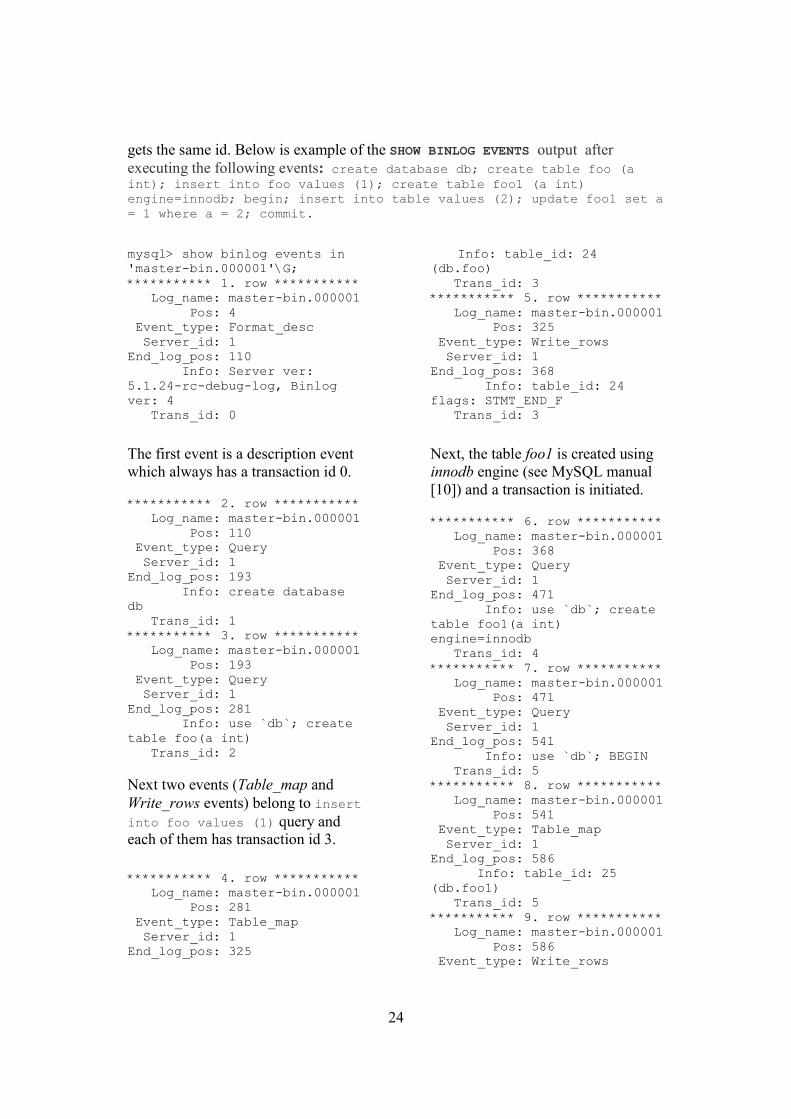
gets the same id. Below is example of the SHOW BINLOG EVENTS output after executing the following events: create database db; create table foo (a int); insert into foo values (1); create table foo1 (a int) engine=innodb; begin; insert into table values (2); update foo1 set a = 1 where a = 2; commit.
mysql> show binlog events in 'master-bin.000001'\G; *********** 1. row *********** Log_name: master-bin.000001 Pos: 4 Event_type: Format_desc Server_id: 1 End_log_pos: 110 Info: Server ver: 5.1.24-rc-debug-log, Binlog ver: 4 Trans_id: 0
The first event is a description event which always has a transaction id 0.
Transaction id together with server id (or master id) identifies a single transaction in a unique way since each master server will start its own transaction id sequence, starting with 1. It can be useful when you have a topology with more than one master.
Limitations of the solution
With current implementation, when master restarts after a failure (or shutdown) it will not continue the id sequence where it left off before the failure (or shutdown). Transaction id sequence will start with 1 again. The proposal is to look at the binary logs contents to find the last transaction id which the server generated before the crash and issue the value larger by one. This need to be performed only once at the master restart. Some slaves can take over the master several times. Thus, slaves have to continue the id sequence where they left off during the time of being master. This issue has to be resolved before the concept of global transaction id can be used fully automatically (see section 6.2).
5.2 Introduction of transaction_info Table
So, how to find the offset using the concept of global transaction id? Searching in the binary log files on the new master to locate a specified transaction id for each slave in the system is not the most efficient and easiest process. The next step was about to analyse what information about a single transaction apart from transaction id can be extracted from the binary log and stored in some data structure. The new data structure has to allow an easy access to the data.
26
Since each master server will start its own transaction id sequence, both a transaction and server id required to identify each transaction uniquely. To construct CHANGE MASTER TO, log name and the offset to replicate from are also needed.
According to accomplished analysis, a database table was added to the system database mysql together with other system tables. The table is named transaction_info.
There are several reasons why a table was chosen instead of other data structures. The most important one is that it makes possible for slaves to get the information they need from the new master in case of master failure. You can also use the table for other purposes. This is covered in section 5.3.
Results
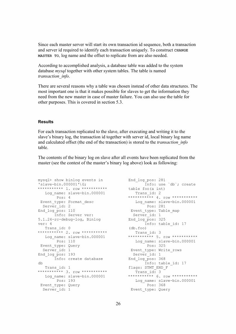
For each transaction replicated to the slave, after executing and writing it to the slave’s binary log, the transaction id together with server id, local binary log name and calculated offset (the end of the transaction) is stored to the transaction_info table.
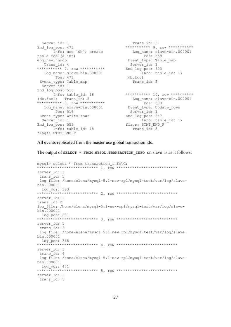
The contents of the binary log on slave after all events have been replicated from the master (see the contest of the master’s binary log above) look as following:
log_file: /home/elena/mysql-5.1-new-rpl/mysql-test/var/log/slave-bin.000001 log_pos: 647 5 rows in set (0.01 sec)
Transaction_info table contains information about each transaction on slave, including transaction id, server id, log file and log position. The log_pos in the table indicates the end of the transaction which is needed to execute CHANGE MASTER TO command.
The solution for the issue described in the previous section, i.e. to find the last transaction id that the master generated before the crash, could be to record the last transaction id by extracting the information from the most current slave’s transaction_info table. The problem is that there is a risk that the last transaction before the crash has been committed on master but not replicated to the slaves. It will result in data loss on slaves but also in two transactions with the same id in the master’s binary log after switching to the original master again.
Limitations of the solution
With current implementation, transaction_info table is only updated on slaves. This means that there are no records about executed transaction in the transaction_info table on master. This is considered to be a future feature (see section 6.2).
5.3 Failover with the New Features
In the event of master failure slaves has to be redirected to the new master using CHANGE MASTER TO command. As it is described in section 4.2, you can either point your slaves to the new master’s current position (but then you can miss some events) or you can try to figure the corresponding positions (or offsets) for each slave in the new master’s binary log. The log name and the offset are needed to be specified since log positioning is different on each slave.
All information required to execute CHANGE MASTER TO is now available in the transaction_info table on slave. But first we need to make sure that all slaves have processed all events in their relay logs and find the most up to date slave to become a new master.
Algorithm of switching master during failover, described in chapter 4.1, can now be described using the introduction of the global transaction id and transaction_info table.
29
5.4 Failover Algorithm
The replication model is a single master with slaves. We will look at the configuration with three slaves (slave 1, slave 2 and slave 3). All updates take place at the master. After some time updates are propagated to the slaves. There are some considerations to make before studying the algorithm.
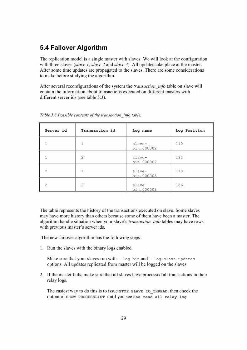
After several reconfigurations of the system the transaction_info table on slave will contain the information about transactions executed on different masters with different server ids (see table 5.3).
Table 5.3 Possible contents of the transaction_info table.
Server id Transaction id Log name Log Position
1 1 slave-bin.000002
110
1 2 slave-bin.000002
193
2 1 slave-bin.000003
110
2 2 slave-bin.000003
186
The table represents the history of the transactions executed on slave. Some slaves may have more history than others because some of them have been a master. The algorithm handle situation when your slave’s transaction_info tables may have rows with previous master’s server ids.
The new failover algorithm has the following steps:
1. Run the slaves with the binary logs enabled.
Make sure that your slaves run with --log-bin and --log-slave-updates options. All updates replicated from master will be logged on the slaves.
2. If the master fails, make sure that all slaves have processed all transactions in their relay logs.
The easiest way to do this is to issue STOP SLAVE IO_THREAD, then check the output of SHOW PROCESSLIST until you see Has read all relay log.
30
3. Determine the most up to date slave.
By examining transaction_info table on each slave determine which one is the closest to the master. It can be done by running SELECT MAX (trans_id) FROM mysql.transaction_info WHERE server_id = master_server_id, where master_server_id is the server id for the current master.
The slave that has the transaction id with the maximum value for the specified server id is the most up to date and therefore will be promoted to become a new master.
4. Find the corresponding offsets for each of the remaining slaves in the new master’s binary log.
Suppose that slave 1 has been promoted to become a new master. For the other slaves (slave 2 and slave3):
a. Find the transaction id of the last transaction executed locally in the transaction_info table. It can be done by SELECT MAX (trans_id) FROM mysql.transaction_info WHERE server_id = master_server_id.
b. Locate the offsets for slave 2 and slave 3.
On the slave being promoted, slave 1, run SELECT log_file, log_pos FROM mysql.transaction_info WHERE trans_id =value AND server_id =
master_server_id, where value is the found transaction id in step (a).
This is will give you the log name and the offset needed to execute CHANGE MASTER TO command.
5. Redirect slaves. On slave 2 and slave 3:
a. Issue STOP SLAVE.
b. Use the found log file and offset in step (4) to redirect slaves using CHANGE MASTER TO (see below) and issue START SLAVE.
CHANGE MASTER TO
MASTER_HOST='slave1',
MASTER_USER='repl_user',
MASTER_PASSWORD='replication',
MASTER_PORT=3307,
MASTER_LOG_FILE='slave1-bin.000001',
MASTER_LOG_POS=647;
31
5.5 Switching Back to the Original Master
When the original master (or Master) is up again there are two choices. You can either make Master a master again or you can make Master a slave. Below follows my proposal of how it can be accomplished without loosing any updates, as addition to the work performed.
1. Make Master a master again.
Note that in the current implementation when Master is restarted the transaction id sequence will start with 1 again. As a result, the transaction_info table will not be updated since it already has the transaction with id 1 and master’s server id (probably 1 again). For the rest, we assume that this problem has been solved so the master will continue the id sequence where it left off.
Unfortunately with current implementation you will not have any help from transaction_info table on master since the table is only updated on slaves. As soon as slave 1 becomes a new master, records about executed transactions will not be written to the transaction_info table (see chapter 5.2 Limitation of the Solution). Slave 2 and slave 3, on the other hand, will have all the records in their tables, including transactions from slave 1 during it’s time of being master.
a. Run Master with binary logs enabled.
Run Master with --log-slave-updates option. All updates replicated from the new master will be logged on the original master.
b. Make sure that slave 2 and slave 3 have processed any transaction in their relay log.
Issue STOP SLAVE IO_THREAD, then check the output of SHOW PROCESSLIST until you see Has read all relay log.
c. Make sure that Master catches up all missed updates from slave1.
Locate the id for the last transaction executed on Master before the failure. Use the found transaction id to find the offset on slave1 using SHOW BINLOG EVENTS command or looking at the output of mysqlbinlog. Then issue CHANGE MASTER TO using the found offset and log name and run START SLAVE.
d. Locate the offset on Master. Redirect all slaves.
On Master, find the offset and the current log file using SHOW MASTER STATUS.
On each slave issue STOP SLAVE and CHANGE MASTER TO using the found offset and log name.
32
CHANGE MASTER TO
MASTER_HOST='master',
MASTER_USER='repl_user',
MASTER_PASSWORD='replication',
MASTER_PORT=3306,
MASTER_LOG_FILE='master-bin.000002',
MASTER_LOG_POS= 960;
Finally, issue START SLAVE.
2. Make Master a slave.
a. Run Master with binary logs enabled.
Make sure that Master run with --log-slave-updates option. All updates replicated from the new master will then be logged on the old master and the information about transaction will be recorded to the transaction_info table on the old master.
b. Set your Master to replicate from the new master, slave 1.
Execute step (c) from the previous algorithm for making Master a master again, i.e. find the Master’s offset on slave1, and issue CHANGE MASTER TO and START SLAVE.
The process of letting the original master to be a master again is more complex. Anyway, with transaction_info table on master as a future feature (see chapter 6.2) the algorithm of switching back to the original master would be as simple as the failover to the new master algorithm.
5.6 Implementation of Failover Algorithm
To show how switching to the new master during failover can be performed the failover algorithm being developed during this work has been implemented. The prototype is a script written in Perl programming language. The script sets up a new topology where the most up to date slave has become a new master and other slaves are redirected to the new master. The script is in appendix B.
33
6 Conclusions
More than ever before, today’s business applications depend on data from multiple databases. Whether deploying applications to provide customers with real-time access and or supply management with real time information.
This thesis comprise several areas of study within replication technology, such as replication protocols and failover but the general idea is to provide studying of replication solutions and participate in the replication solutions development. I became a part of the MySQL open source database development process to provide better services within replication solutions.
During the work the concept of global transaction id was introduced to MySQL replication. Transaction id became a result of analysis of the problem of finding the slave’s offsets in the new master’s binary log in a topology with a single master and slaves to be able to solve the more complex problem of switching to the new master during failover.
The next step was to use the new concept efficiently. As a result transaction_info table was introduced. On each slave the table collects information about transactions executed on master, including master server id, transaction id, local log file name and the offset in the log. The information presented in the transaction_info table is used to change the master and redirect the slaves during failover in the event of master failure.
The prototype is an implementation of the failover algorithm being developed using the introduced concepts of global transaction id and transaction information table. The script, attached to the report, sets up a new topology where the most up to date slave has become a new master and other slaves are redirected to the new master with minimal loss of transaction.
The solution being developed during this work still has some limitation. The most important issue that has to be resolved before the concept of global transaction id and transaction_info table can be used fully automatically (see chapter 6.2) is to ensure that the current master continues the id sequence where it left off before the crash (or shutdown) or during its last time being master.
With the new features introduced to MySQL replication it is possible to create a monitoring program that does automatic failover between MySQL servers.
6.1 Work Performed
The following work has been performed during master thesis:
34
o Description of the replication technology, i.e. traditional replication techniques and protocols.
o Description of the main database management system’s replication techniques and propagation mechanisms.
o Description of the MySQL Replication.
o Definition of the failover in the distributed database systems.
o Description of failover algorithm at MySQL Replication and introduction of the problem.
o Introduction of global transaction id and a new system table to MySQL Replication, i.e. studying existing C++ code and adding new functionality to it.
o Presentation of the new algorithm for switching to the new master during failover.
o Implementation of the algorithm.
6.2 Future Features
Failover management is a complex problem which requires time and recourses. There are number of features that are needed before the process of failover at MySQL replication can be automated. Here is my proposal for the to-do list:
o Ensure that the current master continues the id sequence where it lefts off.
o Introduce the transaction_info table on master, so the process of switching back to the master can be implemented.
o Configure (auto-) purging of the transaction_info table, since the table gradually grows.
o Expand CHANGE MASTER TO command so it can take transaction id and server id.
Master-slave topology is only a single case where transaction id and transaction_info table concepts can be used during failover. Dual master, Ring Replication and other topologies, described in chapter 3, also requires an algorithm for failover management without any loss of updates. I hope that this report with its ideas and proposals will help the future development of the failover solutions for different topologies within MySQL replication.
35
6.3 Other Areas of Use
You can also use the global transaction concept and transaction_info table records for other purpose, for example:
o Locate a transaction on any server using transaction id.
o Identify if slaves are current enough to SELECT from them.
o Find the most up to date slave.
36
Abbreviations
DBMS Database Management System
DBS Database System
2PC Two phase commit
3PC Three phase commit
ROWA Read-one/write-all
ROWA-A Read-one/write-all-available
FIFO First-in-first-out
37
References
[1] M. T. Özsu and P. Valduriez. Principles of Distributed Database Systems. Prentice Hall, 1999.
[2] P. Bernstein, V. Hadzilacos, and N. Goodman. Concurrency control and Recovery in database System. Addison-Wesley, 1987.
[3] A. Silberschatz, H. Korth, and S. Sudarshan. Database System Concepts. Fifth edition, 2005.
[5] Wiesmann, M. Pedone, F. Schiper, A. Kemme, and B. Alonso. Oper. Syst. Lab., Swiss Fed. Inst. of Technol., Lausanne. Understanding Replication in Databases and Distributed Systems, 20th IEEE International Conference on Distributed Computing Systems (ICDCS’00), 2000. http://ieeexplore.ieee.org/search/wrapper.jsp?arnumber=840959, IEEE, 21 January 2008.
[6] M. Wiesmann, M. Pedone, F. Schiper, A. Kemme, and B. Alonso. Database replication techniques: a three parameter classification. Dept. de Syst. de Commun., Swiss Federal Inst. of Technol., Lausanne. The 19th IEEE Symposium on Reliable Distributed Systems SRDS-2000, 2000. http://ieeexplore.ieee.org/xpl/freeabs_all.jsp?arnumber=885408, IEEE, 21 January 2008.
[7] Matthias Wiesmann and André Schiper. Beyond 1-Safety and 2-Safety for
Replicated Databases: Group-Safety. Advances in Database Technology - EDBT 2004, pages 165 – 182, Springer Berlin / Heidelberg. http://www.springerlink.com/content/2c38vxc50ft6676b/, Springer, 2 February 2008.
[8] Matthias Wiesmann and Andre Schiper. Comparison of Database Replication Techniques Based on Total Order Broadcast. Knowledge and Data Engineering, IEEE Transactions on Volume 17, Issue 4, Pages: 551 - 566 , 2005. http://ieeexplore.ieee.org/search/wrapper.jsp?arnumber=1401893, Springer, 2 February 2008.
[9] K. Daudjee and K. Salem. Lazy Database Replication with Freshness Guarantees. School of Computer Science, University of Waterloo, Ontario, Canada, Technical Reports (2002). http://www.cs.uwaterloo.ca/research/tr/2002/, 25 January 2008.
38
[10] MySQL Replication 5.1, Reference Manual. http://dev.mysql.com/doc/refman/5.1/en/replication.html, 21 January 2008.
[11] Jeremy D. Zawodny and Derek J. Balling. High Performance MySQL. Chapter 7, Replication, pages 129 – 168. O’Reilly Media, 2004.
[12] MySQL High Availability Solution. A MySQL Technical Write Paper, 2006.
[13] MySQL Replication, Presentation Slides 2.http://akipp.com/larsthalmann.com/blog/wp-content/uploads/2007/04/070424.ThalmannKindahl.ReplicationTricks.pdf, 2 February 2008.
[14] MySQL Replication, Presentation Slides 1. http://akipp.com/larsthalmann.com/blog/wp-content/uploads/2006/07/060727.LarsThalmann.FutureOfMySQLReplication.p df, 2 February 2008.
[15] SQL Server Replication 2008, Manual. http://technet.microsoft.com/en-us/library/ms151198(SQL.100).aspx, 30 January 2008.
[16] MySQL Replication Tutorial. http://forge.mysql.com/wiki/Replication/Tutorial, 21 January 2008.
[18] A Practical Guide to DB2 UDB Data Replication V8, Manual. http://www.redbooks.ibm.com/redbooks/SG246828.html, 1 February 2008.
[19] Data replication 1. http://www.cs.mcgill.ca/~cs577/lectures/577-replication.pdf, 23 January 2008.
[20] Data replication 2. http://www.comp.nus.edu.sg/~tankl/cs5225/2008/rep6.pdf, 23 January 2008.
39
Appendix A: Code
This appendix contains the implementation of the failover algorithm, described in chapter 5. The result of running the script is a new replication topology where the most up to date slave has become a new master and other slaves are redirected to the new master.
#! /usr/bin/perl -w use strict; use DBI; my $dsn; my $user_name = "repl_user"; my $password = "xyzzy"; my $master_server_id = 1; my @slaves=([0, "slave1",12001,"/tmp/slave1.sock"], [1, "slave2",12002,"/tmp/slave2.sock"], [2, "slave3",12003,"/tmp/slave3.sock"]); my $dbh; my $sth; my $new_master; my $max_trans_id = 0; my @slaves_for_change; my $slave_number; my @ary; my $trans_id; #Make sure that all slaves have processed any statements in their relay log. for my $server (@slaves) { my $slave = $server->[1]; my $port = $server->[2]; my $socket = $server->[3]; $dbh = DBI->connect("DBI:mysql:db:localhost;port=$port;mysql_socket=$socket", $user_name, $password,{RaiseError =>1, PrintError => 0}); print "$slave \n"; $sth = $dbh->prepare ("stop slave io_thread"); $sth->execute ();
40
$sth = $dbh->prepare ("select count(*) from information_schema.processlist where state like 'Has read all relay log%'"); my $count = 0; my $start = 0; use Time::HiRes; while ($count == 0) { $start=times(); $sth->execute (); @ary= $sth->fetchrow_array(); ($count) = @ary; print "$count \n"; if ($count == 0) { Time::HiRes::sleep (2.5); } } } # Find the most up to date slave for my $server (@slaves) { $slave_number = $server->[0]; my $slave = $server->[1]; my $port = $server->[2]; my $socket = $server->[3]; $dbh = DBI->connect("DBI:mysql:mysql:localhost;port=$port;mysql_socket=$socket",$user_name, $password,{RaiseError =>1, PrintError => 0}); print "$slave \n"; $sth = $dbh->prepare ("select max(trans_id) from mysql.transaction_info where server_id = $master_server_id"); $sth->execute (); @ary= $sth->fetchrow_array(); ($trans_id) = @ary; if($max_trans_id < $trans_id) { $max_trans_id = $trans_id; $new_master=$server; } else { push(@slaves_for_change, [$slave_number, $trans_id]); }
41
print"max trans_id = $max_trans_id, server_id = $master_server_id \n"; } print "new master = $new_master->[0], max trans_id = $max_trans_id \n"; # Redirect other slaves to the new master my $pos; my $log; for my $server (@slaves_for_change) { $slave_number = $server->[0]; $max_trans_id = $server->[1]; $dbh = DBI->connect("DBI:mysql:mysql:localhost;port=$new_master->[2];mysql_socket=$new_master->[3]",$user_name, $password,{RaiseError =>1, PrintError => 0}); print "$slave_number \n"; $sth = $dbh->prepare ("select log_file,log_pos from mysql.transaction_info where server_id = $master_server_id and trans_id = $max_trans_id"); $sth->execute (); @ary= $sth->fetchrow_array(); ($log,$pos)=@ary; print"log = $log, pos = $pos \n"; $dbh = DBI->connect("DBI:mysql:mysql:localhost;port=$slaves[$slave_number]->[2];mysql_socket=$slaves[$slave_number]->[3]",$user_name, $password,{RaiseError =>1, PrintError => 0}); print"$slaves[$slave_number]->[1] \n"; $sth = $dbh->prepare ("stop slave"); $sth->execute (); my @ary_log=split('/',$log); my $log_name = pop(@ary_log); print"$log_name \n"; $sth = $dbh->prepare ("change master to master_host ='localhost', master_user = 'repl_user', master_password = 'xyzzy', master_port = $new_master->[2], master_log_file = '$log_name', master_log_pos = $pos"); $sth->execute (); $sth = $dbh->prepare ("start slave");
Appendix B: Description of the Replication Techniques Used in the Main Database Management Systems
At this step we have knowledge about classical replication techniques and protocols. But to be able to compare and analyse the studied techniques we should probably see how and when there are applied on some of the main database management systems. In this section we will look at Oracle 9i, Microsoft SQL Server and IBM DB2 DBMS’s replication techniques and update propagation mechanisms. The general description of GoldenGate software solutions is also presented.
B.1 Oracle 9i Replication
Advanced Replication is a fully integrated feature of the Oracle DBMS [15]. Oracle offers both synchronous (eager) and asynchronous (lazy) replication. Oracle applies the primary copy and update-everywhere techniques described early in this document by supporting two basic types of sites: master sites (primary site) and materialized view sites (a snapshot). A materialized view is a complete or partial copy (replica) of a target master from a single point in time.
B.1.1 Master Replication Concepts and Architecture
Oracle provides two types of master replication: single master and multimaster replication (also called peer-to-peer or n-way replication). Multimaster replication includes multiple master sites, where each master site operates as an equal peer. A single master site that supports one or more materialized view sites can also participate in a multiple master site environment.
B.1.1.1 Multimaster Replication
Multimaster replication is compromised of multiple master sites equally participating in an update-anywhere model. Updates made to an individual master site are propagated to all other participating master sites. Multimaster replication provides complete replicas of each date item at each of the master site and be-directional communication channels between master sites (see figure B.1).
44
Figure B.1 Multimaster Replication.
Within maser replication Oracle provides both synchronous and asynchronous replication. You can change the propagation mode from asynchronous to synchronous or vice versa for a master site. Also, a multimaster replication environment may contain a mixture of both synchronous and asynchronous replication.
Asynchronous replication independently propagates any data manipulation language (DML) statement or procedure execution to all of the other master sites participating in the multimaster replication environment after they has been executed locally. Propagation occurs in a separate transaction after the DML or replication procedure has been executed locally. For each row that is inserted, updated, or deleted, an internal trigger creates a deferred remote procedure call (RPC) and places it in the deferred transaction queue. If a procedure has been replicated and its wrapper is executed at a master site, then the procedure call is placed in the deferred transaction queue. At scheduled intervals or on-demand, the deferred transactions in the deferred transaction queue are propagated to and applied on the target destinations. Asynchronous replication is the default mode of replication due to less networking and hardware resources than synchronous replication does and, according to Oracle, resulting in better availability and performance. However, asynchronous replication causes data inconsistencies and conflicts due to time delay before changes are installed at the all master sites in the replication environment.
Synchronous replication propagates any changes made at local site to other master sites during the same transaction as initial change (immediately). If the propagation fails at any of the master sites, then the entire transaction, including the initial changes at the local master sites, rolls back. The internal trigger captures any DML and immediately propagates these actions to all other master sites in the replication environment. The internal trigger uses an internal RPC to apply these actions at the destination sites. Data replication RPCs execute within the boundary of the same transaction that modifies the local replica. Like an internal trigger, a wrapper for a replicated procedure immediately propagates the procedure call to all other master sites in the replication environment and applied using RPC.
master site
master site
master site
45
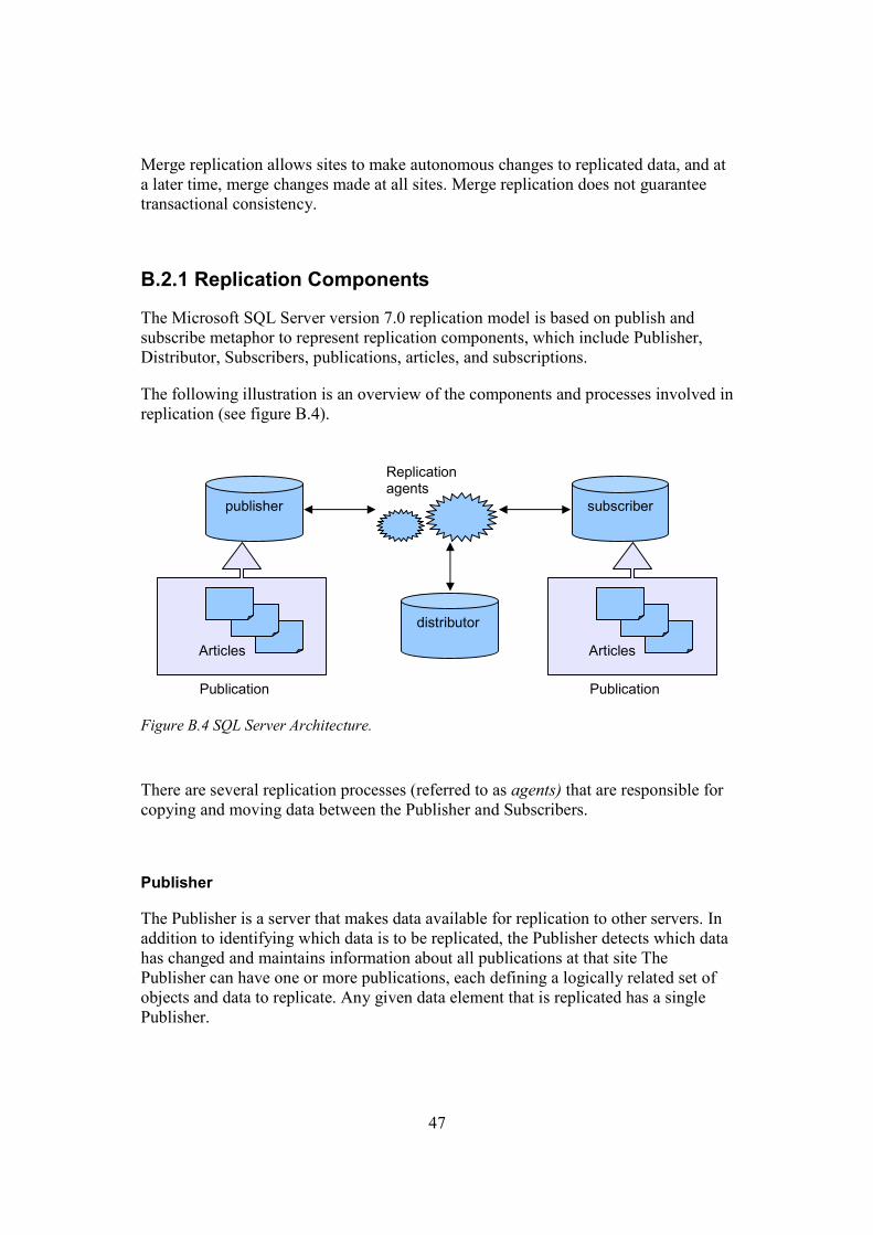
B.1.2 Materialized View Concepts and Architecture
Oracle uses materialized views (also known as snapshots in prior releases) to replicate data to non-master sites in a replication environment and to cache expensive queries in a data warehouse environment.
A materialized view is a replica of a target master from a single point in time. The master can be either a master table at a master site or a master materialized view at a materialized view site. A master materialized view is a materialized view that functions as a master for another materialized view. A multitier materialized view is one that is based on another materialized view, instead of on a master table.
Figure B.2 Materialized View Connected To Single Master Site.
Materialized views can be updated from a single master site, master materialized view site or several masters through individual batch updates, known as a refreshes, (as shown in figure B.2).
In case of fast materialized view site refresh, Oracle examines all of the changes to the master table or master materialized view since the last refresh to see if any apply to the materialized view has to be done. If any changes were made to the master since the last refresh, then it takes some time to apply the changes to the materialized view. If, however, no changes at all were made to the master since the last refresh of a materialized view, then the materialized view refresh should be very quick.
A materialized view can be read-only, updatable, or writable. Users cannot perform data manipulation language (DML) statements on read-only materialized views, but they can do it on updatable and writable materialized views.
Oracle propagates the changes made to an updatable materialized view to the materialized view’s remote master table or master materialized view. The updates to the master then cascade to all other replication sites. Oracle uses its internal triggers,
master site
master site
master site
materialized view
46
deferred transactions, deferred transaction queues to propagate data-level changes asynchronously from an updatable materialized view to its master table.
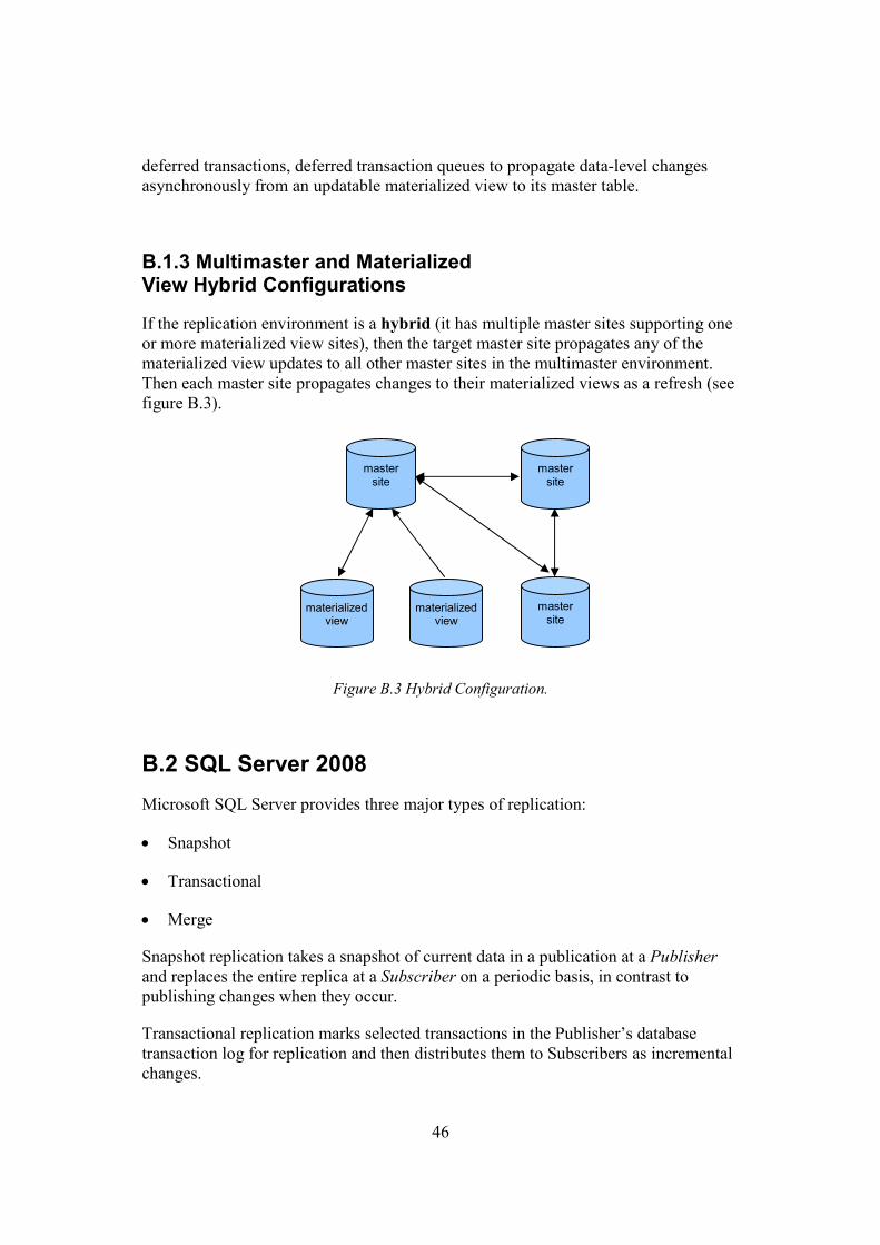
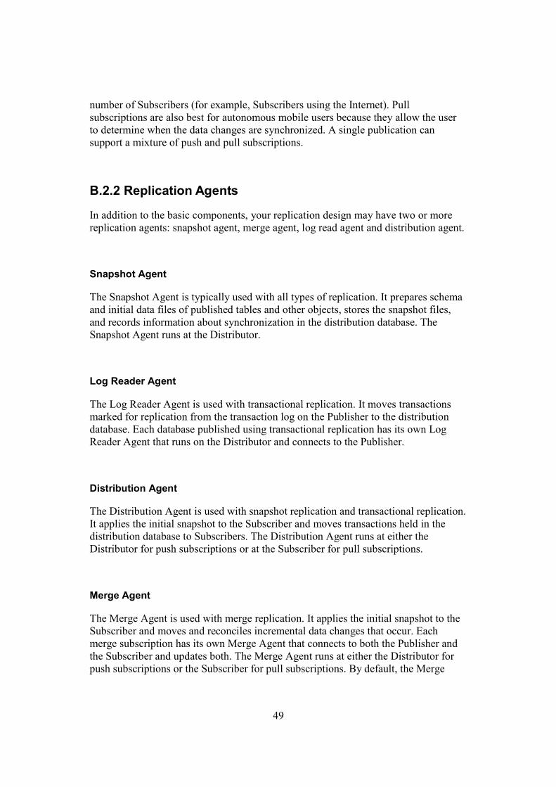
B.1.3 Multimaster and Materialized View Hybrid Configurations
If the replication environment is a hybrid (it has multiple master sites supporting one or more materialized view sites), then the target master site propagates any of the materialized view updates to all other master sites in the multimaster environment. Then each master site propagates changes to their materialized views as a refresh (see figure B.3).
Figure B.3 Hybrid Configuration.
B.2 SQL Server 2008
Microsoft SQL Server provides three major types of replication:
• Snapshot
• Transactional
• Merge
Snapshot replication takes a snapshot of current data in a publication at a Publisher and replaces the entire replica at a Subscriber on a periodic basis, in contrast to publishing changes when they occur.
Transactional replication marks selected transactions in the Publisher’s database transaction log for replication and then distributes them to Subscribers as incremental changes.
master site
master site
master site
materialized view
materialized view
47
Merge replication allows sites to make autonomous changes to replicated data, and at a later time, merge changes made at all sites. Merge replication does not guarantee transactional consistency.
B.2.1 Replication Components
The Microsoft SQL Server version 7.0 replication model is based on publish and subscribe metaphor to represent replication components, which include Publisher, Distributor, Subscribers, publications, articles, and subscriptions.
The following illustration is an overview of the components and processes involved in replication (see figure B.4).
Figure B.4 SQL Server Architecture.
There are several replication processes (referred to as agents) that are responsible for copying and moving data between the Publisher and Subscribers.
Publisher
The Publisher is a server that makes data available for replication to other servers. In addition to identifying which data is to be replicated, the Publisher detects which data has changed and maintains information about all publications at that site The Publisher can have one or more publications, each defining a logically related set of objects and data to replicate. Any given data element that is replicated has a single Publisher.
publisher subscriber
distributor
Replication agents
Articles
Publication
Articles
Publication
48
Distributor
The Distributor is a database instance that acts as a store for replication specific data associated with one or more Publishers. Each Publisher is associated with a single database (known as a distribution database) at the Distributor. The distribution database stores replication status data, meta-data about the publication, and, in some cases, acts as a queue for data moving from the Publisher to the Subscribers. In many cases, a single database server instance acts as both the Publisher and the Distributor. This is known as a local Distributor. When the Publisher and the Distributor are configured on separate database server instances, the Distributor is known as a remote Distributor.
Subscribers
A Subscriber is a database instance that receives replicated data. A Subscriber can receive data from multiple Publishers and publications. Depending on the type of replication chosen, the Subscriber can also pass data changes back to the Publisher or republish the data to other Subscribers.
Publication and Articles
A publication is a collection of one or more articles, and an article is a grouping of data to be replicated. An article can be an entire table, only certain columns or rows, views, stored procedure, and other objects. This grouping of multiple articles makes it simpler to subscribe to a unit (the publication), which has all the relevant and required data. Subscribers subscribe only to a publication, not to individual articles within a publication.
Subscription
A subscription is a request for a copy of a publication to be delivered to a Subscriber. The subscription defines what publication will be received, where, and when. There are two types of subscriptions: push and pull.
With a push subscription, the Publisher propagates the changes to a Subscriber without a request from the Subscriber to do so. Typically, push subscriptions are used in applications that are required to send changes to Subscribers whenever and as soon as they occur (synchronously). Push subscriptions are best for publications that require near-real-time movement of data without polling and where the higher processor overhead at the Publisher does not affect performance.
With a pull subscription, the Subscriber asks for periodic (asynchronous) updates of all changes at the Publisher. Pull subscriptions are best for publications having a large
49
number of Subscribers (for example, Subscribers using the Internet). Pull subscriptions are also best for autonomous mobile users because they allow the user to determine when the data changes are synchronized. A single publication can support a mixture of push and pull subscriptions.
B.2.2 Replication Agents
In addition to the basic components, your replication design may have two or more replication agents: snapshot agent, merge agent, log read agent and distribution agent.
Snapshot Agent
The Snapshot Agent is typically used with all types of replication. It prepares schema and initial data files of published tables and other objects, stores the snapshot files, and records information about synchronization in the distribution database. The Snapshot Agent runs at the Distributor.
Log Reader Agent
The Log Reader Agent is used with transactional replication. It moves transactions marked for replication from the transaction log on the Publisher to the distribution database. Each database published using transactional replication has its own Log Reader Agent that runs on the Distributor and connects to the Publisher.
Distribution Agent
The Distribution Agent is used with snapshot replication and transactional replication. It applies the initial snapshot to the Subscriber and moves transactions held in the distribution database to Subscribers. The Distribution Agent runs at either the Distributor for push subscriptions or at the Subscriber for pull subscriptions.
Merge Agent
The Merge Agent is used with merge replication. It applies the initial snapshot to the Subscriber and moves and reconciles incremental data changes that occur. Each merge subscription has its own Merge Agent that connects to both the Publisher and the Subscriber and updates both. The Merge Agent runs at either the Distributor for push subscriptions or the Subscriber for pull subscriptions. By default, the Merge
50
Agent uploads changes from the Subscriber to the Publisher and then downloads changes from the Publisher to the Subscriber.
B.2.3 Replication Techniques
Thus, SQL Server has tree types of replication: snapshot, transactional and merge replication. The next three capitals describe how each of the replication techniques works and when it’s convenient to use each of them.
B.2.3.1 Snapshot Replication
Snapshot is a copy of all of the objects and data specified by a publication. The Snapshot Agent running on the Distributor reads the publication database and creates files in the snapshot folder, which is also on the Distributor. The Distribution Agent on the Distributor uses the publication data in the snapshot folder to update the Subscribers. Snapshots can be generated and applied either immediately after the subscription is created or according to a schedule set at the time the publication is created.
B.2.3.2 Transaction Replication
Transactional replication typically starts with a snapshot. The Snapshot Agent prepares snapshot files, stores the files in the snapshot folder, and records synchronization jobs in the distribution database on the Distributor. The Log Reader Agent on the distributor reads transactions marked for replication from the Publishers transaction log into the distribution database, which acts as a reliable store-and-forward queue. The Distribution Agent copies the initial snapshot files from the snapshot folder and the transactions held in the distribution database tables to Subscribers.
As Subsequent data changes and schema modifications made at the publisher are usually delivered to the Subscriber as they occur (in near real time). The data changes are applied to the Subscriber in the same order and within the same transaction boundaries as they occurred at the Publisher; therefore, within a publication, transactional consistency is guaranteed. However, data changes can also be propagated to the Subscribers at schedule intervals.
51
Updatable Subscriptions
Updatable subscriptions for transactional replication allow Subscribers to replicate changes to the Publisher. Triggers are added to the published tables in the subscription database, and when a change is made at the Subscriber, it is propagated either directly to the Publisher and applied using Microsoft Distributed Transaction Coordinator (MSDTC) (immediate updating subscriptions) or first to a queue and then applied to the Publisher (queue updating subscriptions).
Changes made at the Publisher are replicated to Subscribers in the same way as transactional publications with read-only Subscribers.
B.2.3.3 Merge Replication
Merge replication is implemented by the SQL Server Snapshot Agent and Merge Agent.
Merge replication, like transactional replication, typically starts with a snapshot of the publication database objects and data. The publisher and subscriber make changes to the database independently. Both entities can work without an active network connection. The subscriber synchronizes with the publisher, when they are reconnected and exchanges all data that have changed between the publisher and subscriber since the last time synchronization occurred.
B.3 DB2 Replication V8
DB2 replication is a very flexible solution which supports many different configurations of both products and servers [16]. This section describes some of the most common configurations. Next section describes some of the most common configurations.
B.3.1 Common Configurations
The data distribution and data consolidation scenarios (described in capitals B.3.1.1 and B.3.1.2) assume that the target tables are updated only by replication, not by any other users or application. This is known as primary copy (or master-slave) replication.
B.3.1.1 Data Distribution
The first configuration involves distribution of data by moving all or a subset of data to one or more location (see figure B.5). Subsets of the data can for example be
52
source server
target server
target server
source table write/read
target table read-only
target table read-only
copied to data marts to provide groups of users with local access. Distribution of data can be also used to provide data to applications in the same or different environments or to provide application e.g. co-existence migration from on environment to another.
Figure B.5 Data Distribution.
The two target servers may be either a full copy or a copy of different subsets, or transformation of the data on different schedules.
B.3.1.2 Data Consolidation
Another configuration involves consolidation of data from remote systems. This model allows a target server to replicate from two source servers, where the target is a union of the sources (see figure B.6). An enterprise may have data on many different distributed systems. Replication can copy changes from each of the distributed sites to a central site to analysis, reporting and for enterprise application processing.
53
peer server
peer server
peer server
peer table write/read
peer table write/read
peer table write/read
target server
source server
source server
source table write/read
target table read-only source
table write/read
Figure B.6 Data Consolidation.
B.3.1.3 Bidirectional Exchange of Data
The data in this configuration can be updated at multiple locations, each location copies changes from all other locations directly. This approach is known as update everywhere or multimaster (or even peer-to-peer) replication (see figure B.7). Multimaster replication can be used to maintain disaster recovery sites, to provide fail-over systems for high availability, and to balance query workload across multiple locations.
Figure B.7 Bidirectional Exchange of Data.
One server can also serves as a master in this configuration and distribute changes to the other servers (target sites). Changes made at the targets then flows to other targets
54
sites through the master. This hybrid model can be used for mobile applications where the target may be a computer in a branch office or in a delivery truck. Often, there are many targets and they are only occasionally connected to the source system. The connection may be via phone lines, so efficiency is important.
DB2 also support multitier technique, where changes are copied from a central source to a staging area on another site (can be another system) and then copied from the staging area to the desired target location. This is useful when there are many target location because it minimize the impact on the source system.
B.3.2 Replication Components
There are four components which handle replication IBM replication: Administrator, Capture, Apply and Alert monitor (see figure B.8).
B.3.2.1 Administrator
Administrator manages the other three components using replication center. Replication Center is a graphical user interface used to define replication source and map sources to the targets.
55
unit of work
Log
Change Data
control
Capture
Source
Target
control
Apply
Target
Target
DB2
Source DB2 Target
Initialization from the source table or view
Apply captured changes
Figure B.8 Propagation mechanism.
B.3.2.2 Capture
Changes to DB2 source tables are captured by a Capture program running at the source server. When changes are made to the source table, DB2 writes log records.
Each source table has a corresponding Change Data (CD) table where the captured changes are stored. Capture uses Unit of Work (UOW) control table to store commit information.
The bidirectional hybrid replication requires that each site has a Capture and an Apply program. Multimaster replication has a Capture and at least one Apply program to copy changes from all other sites.
56
B.3.2.3 Apply
Captured changes are applied to the target tables by Apply programs. The apply program can run on any server and must have connectivity to both the source and the target servers.
The Replication Center is used to map a source table or view to a target table. You define a subscription set which is group of one or more target tables (called subscription members) that will be processed as a unit by Apply. The changes from CD tables are applied for each table separately, in the same order the occurred at the source. A single commit is issued after the last member in the set is processed.
Apply selects from source tables for the first initialization of the targets. This is called full refresh. After a full refresh, Apply selects changes from the CD tables and applies those changes to the target tables. Apply can run as a batch process or as a task that runs all the time. I assume that the periodicity with which Apply installs the changes indicate the type of propagation, either immediate or deferred.
B.3.2.4 Alert Monitor
The Alert Monitor program collects information from the capture and applies control tables. It also uses the Database Administration Server (DAS) installed on the Capture and Apply servers to receive remote commands and supply system information.
B.4 GoldenGate Software
GoldenGate Software offers Transactional Data Management (TMD) technology solutions that allow high volumes of transactional data to be moved across heterogeneous IT environments with sub-second latency and guaranteed accuracy, reliability and integrity. GoldenGate Software enables real-time access to real-time information for business applications.
B.4.1 GoldenGate Architecture
GoldenGate’s TMD architecture is focused on three capabilities: real-time – operating with sub-seconds latency; heterogeneity – supporting a variety of hardware, operational systems and database platforms; transactional– maintaining the integrity of data transactions (the completeness and accuracy of data).
GoldenGate TMD architecture three modules: GoldenGate Capture, GoldenGate Trails, and GoldenGate delivery.
57
B.4.1.1 GoldenGate Capture
The GoldenGate Capture module captures the result of insert, update and delete operations executed against database as they occur, and them routs them for distribution. GoldenGate Capture uses transaction logs to capture committed transactions. No additional tables are required to run GoldenGate Capture and overhead is reduced as opposed to trigger-based capture techniques.
GoldenGate capture allows users to filter tables and rows by ignoring the entries that are irrelevant. It can reduce network bandwidth requirements in a number of ways. Individual records can be bounded into lager, more efficient packets and avoiding record-at-time bottleneck. Several levels data compression is available. Users can also use several GoldenGate capture modules to maintain minimal lag time between source and target systems.
GoldenGate also checkpoints the last changed transactions whenever a commit boundary is encountered. Checkpoints store the current position as processed by both GoldenGate Capture and GoldenGate Delivery. Using these positions GoldenGate can restart in the event of network or system failure.
B.4.1.2 GoldenGate Trails
GoldenGate Trails is a queuing mechanism which contains the most recent changes data operations in a platform independent format. Trail records are stored in a GoldenGate Universal Data Format (UDF) and users can convert them to other formats for consumption by different applications. Trail files can be placed on the target, the source system, or both. GoldenGate uses decoupled architecture trough staging data in GoldenGate Trails. It provides each module the ability to perform its tasks independent of other modules or components.
Sometimes it can be preferable to create Trail files on the source system and use a separate component, called “Data Pump” to continuously push the Trail files from the source to the target systems. This configuration enhances the fault tolerance and reliability of the overall GoldenGate environment and can be useful in the event of network failure since the data can be queued up locally.
B.4.1.3 GoldenGate Delivery
The GoldenGate Delivery component takes any changed transactional data that has been placed in a GoldenGate Trail and immediately applies in to the target database. GoldenGate Delivery applies each database change in the same order as they were committed in the source database to ensure data integrity. It applies changes within the same transaction context.
58
Cascading Scalability, Database Tying
Unidirectional Reporting Instance
Bidirectional Instant failover, “Active-Active”
Peer-to-Peer Load balancing, High Availability
Consolidation Data Warehouse
Broadcast Data Distribution
By default, GoldenGate Delivery populates any target table column with data from a source table column if the two columns share the same name; this includes like-named tables as well. However, one can easily configure GoldenGate to move data from a single table into multiple target tables or vice-versa. Users can also define explicit mapping and transformation rules.
B.4.2 Key Features of the GoldenGate TMD Platform
Because of its decoupled modular design, GoldenGate supports a wide variety of topologies. These includes one-to-many, many-to-one and many-to-many – for unidirectional and bidirectional configurations (see figure B.9).