Bell Road ASCT Comprehensive Study Final Report Prepared For: Maricopa County Department of Transportation In Coordination with Partner Agencies: Supported By: Maricopa Association of Governments October, 2019
Transcript
Bell Road ASCT Comprehensive Study
Final Report
Prepared For: Maricopa County Department of Transportation
Appendix A Survey Instrument and Reponses........................................................................... 34
Appendix B Methodology Memorandum.................................................................................... 35
Appendix C Detailed Project Area Results ................................................................................ 36
Figures
Figure 1: Project Vicinity Map ...................................................................................................... 7 Figure 2: Systems Engineering “V” Diagram ............................................................................... 9 Figure 3: Project Segmentation ................................................................................................. 15 Figure 4: Project Area 1 Weekday Travel Time .......................................................................... 24 Figure 5: Project Area 1 Weekend Travel Time ......................................................................... 25 Figure 6: Project Area 2 Weekday Travel Time .......................................................................... 26 Figure 7: Project Area 2 Weekend Travel Time ......................................................................... 27 Figure 8: Purdue Phase Coordination ....................................................................................... 28 Figure 9: Project Area 3 Weekday Travel Time .......................................................................... 29 Figure 10: Project Area 3 Weekend Travel Time ....................................................................... 30 Figure 11. Project Area 4 Weekday Travel Time ........................................................................ 31 Figure 12. Project Area 4 Weekend Travel Time ....................................................................... 32
Bell Road ASCT Comprehensive Study
Prepared for: Maricopa County Department of Transportation
AECOM
Tables
Table 1: Responses to Likert Scale Survey Questions .............................................................. 19 Table 2: Project Area 1 Results Summary ................................................................................. 24 Table 3: Project Area 2 Results Summary ................................................................................. 26 Table 4: Project Area 3 Results Summary ................................................................................. 29 Table 5. Project Area 4 Results Summary ................................................................................. 31
Appendix
Appendix A: Survey Instrument and Responses Appendix B: Methodology Memorandum Appendix C: Detailed Project Area Results Appendix D: Concept of Operations Appendix E: Operations Plan Appendix F: Bell Road ASCT DCR
Bell Road ASCT Comprehensive Study
Prepared for: Maricopa County Department of Transportation
AECOM 6
1. Introduction
Bell Road is an east-west corridor roadway stretching across the Phoenix Metropolitan Area from the western edge of Surprise to the eastern edge of the Scottsdale: the corridor passes through several cities and jurisdictions. As such, traffic control signals along Bell Road are controlled by seven public agencies:
• City of Surprise
• City of Peoria
• City of Glendale
• City of Phoenix
• City of Scottsdale
• Maricopa County Department of Transportation (MCDOT)
• Arizona Department of Transportation (ADOT)
The agencies listed above have worked together as the Bell Road Coordination Committee – a subcommittee to the AZTech partnership – for years to improve mobility along Bell Road and best serve travelers. Starting in spring 2018, the agencies began to convert the traffic control signals along portions of Bell Road to Adaptive Signal Control Technology (ASCT) as part of an ASCT pilot program coordinated by MCDOT and AZTech. The purpose of the report herein is to document the history of the project, the procedure used in implementation of ASCT, the lessons-learned during deployment, and the quantitative results of the change.
Stretching approximately 36 miles across the area from east to west, Bell Road straddles Phoenix and its suburb cities of Surprise, Peoria, Glendale, and Scottsdale. It crosses the Agua Fria River and provides interchange access to five major freeways (SR 303L, SR 101L Agua Fria, I-17, SR 51, and SR 101L Pima) and one major US highway (US 60/Grand Avenue). Due to the length and accessibility of Bell Road across the metropolitan area, the corridor is used heavily by commuters, freight, and other vehicle traffic, making it the highest-volume arterial in the metropolitan area. Traffic data from the ADOT MS2 Transportation Data Management System along Bell Road for year 2018 describes average daily traffic (ADT) as high as 70,950 vehicles per day (vpd). As a 6-lane regional arterial, the capacity on Bell Road is 45,000 – 48,000 vpd, making it over-capacity and a prime candidate for inter-agency ITS coordination. At the border with Scottsdale, Bell Road curves slightly southeast and becomes Frank Lloyd Wright Boulevard. Figure 1 provides a map of the metropolitan area with Bell Road’s location highlighted in red.
Bell Road ASCT Comprehensive Study
Prepared for: Maricopa County Department of Transportation
AECOM 7
Figure 1: Project Vicinity Map
Bell Road ASCT Comprehensive Study
Prepared for: Maricopa County Department of Transportation
AECOM 8
2. Collaboration
The Phoenix Metropolitan Area – also called the Valley of the Sun, or simply the Valley by residents – is a geographically vast, sprawling urban area near the center of Arizona. With the city of Phoenix at its center, the metropolitan area contains suburb cities in nearly every direction. Started in 1996, the AZTech partnership is a staple of local agency cooperation, allowing the agencies in the Valley to share data and collaboratively implement Intelligent Transportation System (ITS) to solve traffic challenges. The Bell Road Coordinating Committee is a sub-committee of this partnership with the goal of collaborative implementation of strategies for improving throughput and safety on this major arterial.
Prior to the ASCT Pilot Project, the Bell Road Partners implemented other ITS projects with the goal of improving traffic progression along Bell Road. MCDOT partners developed a comprehensive Bell Road ITS plan and implemented Pan-Tilt-Zoom cameras and CCTV cameras along the corridor to achieve more comprehensive vehicle detection. In addition, dynamic message signs were implemented to improve traveler information and a project to update and improve fiber communications along the corridor was completed. The committee investigated options for increasing capacity along the corridor, and initially considered a roadway widening option. This option would have had substantial right-of-way and utility impacts. As a result, a widening project would have cost approximately 15 times as much as a technology solution, and cost approximately twice as much in annual recurring costs, thus making a technology solution favorable. Eventually the Bell Road ASCT Pilot Project was initiated, and adaptive signal systems and corresponding detection systems were installed at several intersections along the corridor, focusing on interchanges with regional freeways and their surrounding intersections.
The Maricopa County Department of Transportation (MCDOT), along with its partner agencies that control signals across the Bell Road corridor, recently completed a pilot project for converting signal timings to ASCT. The project was preceded by a thorough Systems Engineering process, which followed the FHWA guidelines for ITS.
3. History of the Bell Road ASCT Project
The Bell Road Coordination Committee (BRCC) was established to address traffic management along the corridor and meet the growing traffic demand. The BRCC established a Bell Road Operations Plan.
The BRCC met periodically to coordinate their efforts to improve Bell Road traffic flow. Several attempts were made to coordinate signal timing plans with progression from one jurisdiction to the next. The agency partners found that timing plans were needing to be re-estimated more often than they would prefer with fluctuations in volumes. Additionally, coordinated timing plans were not able to account for differences in the controller clocks across jurisdictions.
Coordinating Committee Goals - Provide a seamless commute - Provide signal timing progression - Keep up with seasonal and special event traffic - Improve travel time and safety
Bell Road ASCT Comprehensive Study
Prepared for: Maricopa County Department of Transportation
AECOM 9
The BRCC began to discuss the option of incorporating ASCT and a pilot was proposed for the MAG Transportation Improvement Program (TIP) by the partner agencies. In 2012, the City of Peoria began operating adaptive signals along a portion of Bell Road and found that the technology worked well for their needs. However, Peoria turned this system off and relocated it to another part of the city, to join a pilot program with partner agencies. A Systems Engineering process was initiated in which several pre-engineering considerations were made to determine if ASCT should be implemented and how the implementation should take place.
This pilot project was funded through the Maricopa Association of Governments (MAG) Congestions Mitigation and Air Quality (CMAQ) grant, with a local agency match. The project is also considered a Federal Highway Administration (FHWA) Project of Division Interest (PoDI) due to the level of complexity, the multi-jurisdiction coordination, and the associated risk. The PoDI project attracts national interest in the outcomes. The overall budget for this project came to $2.7 Million. $1.8 Million of that budget (68%) went toward the ASCT Systems themselves, with the inclusion of a 6-year maintenance and support services contract. The remainder was spent on vehicle detection, wi-fi readers, and measuring performance.
3.1 Systems Engineering
The preliminary engineering efforts on this project were instrumental in ensuring the smooth transition to ASCT. MCDOT, as the champion agency of this project, was responsible for managing the systems engineering efforts with input from partner agencies. At the onset of the project MCDOT made a commitment to follow the Systems Engineering for Intelligent Transportation Systems guidelines published by Federal Highway Administration (FHWA). Figure 2 provides the System Engineering “V” Diagram provided by FHWA to guide the systems engineering process. MCDOT was able to save time and resources by adopting this system, which had already been developed and tested by FHWA.
Figure 2: Systems Engineering “V” Diagrami
Prior to moving forward, AzTech requested a peer exchange in order to understand the technologies and methodologies available for completing this pilot project. FHWA arranged that
Bell Road ASCT Comprehensive Study
Prepared for: Maricopa County Department of Transportation
AECOM 10
peer exchange, which was attended by several technology vendors. This arrangement provided a learning opportunity for those involved from every agency, and an opportunity for vendors to educate the various agency representatives on the details of their technology, and how each differs from the rest.
The Concept of Operations and the System Requirements documents were developed at the onset of the project. These two documents reflect steps 1 and 2 in the V-diagram shown above. The FHWA systems engineering guidelines provide templates and step-by-step outlines for these two documents. In addition to the peer exchange, a training session was held on the Concept of Operations and System Requirements. The training provided an opportunity for all agencies involved to get on the same page and understand the direction the pilot project would take.
In addition to the Concept of Operations and System Requirements documents, MCDOT developed a Design Concept Report (DCR) with high level design of the project areas. This aligns with the next steps in the Systems Engineering “V” Diagram.
3.2 Procurement
The success of the project was dependent on choosing the right vehicle detection and ASCT technology vendor. The partner agencies jointly decided to each complete their own procurement process, potentially each selecting a different vendor, because each project area had its own priorities and challenges.
Through a discussion among FHWA, MCDOT, and the other agency partners and an understanding of the limitations of the funding, the decision was made to hold two separate procurement strategies for vehicle detection and ASCT technology. The ASCT technology itself was procured through a Request for Proposals (RFP) which is not dependent on budget. The detection systems and installation which would support the ASCT were procured through a low-cost bid. This dual procurement process posed challenges in later stages of the pilot project, primarily stemming from the lack of coordination between the vendors, suppliers, and installation groups. Specific wording in the RFP made it difficult to accommodate those vendors which did prefer to come with their own detection, or those that preferred to partner with a specific detection technology and/or installation process.
The plans that were developed as part of the DCR for this pilot project were included in the RFP.
Lesson Learned: The FHWA template for the Concept of Operations and the
System Requirements was beneficial to the project. It’s use mitigated the risk of under or over developing the documents, and saved resources by providing starting points for document acceptance.
Lesson Learned: In future efforts,
wording in the RFP could be included to reflect procurement of the total system, which could (or should, depending on the agency’s preference) include detection.
Lesson Learned: In future efforts, the plans included in the RFP should not include the detection system, in order to allow flexibility for vendors to arrange detection system plans that work with their products.
Bell Road ASCT Comprehensive Study
Prepared for: Maricopa County Department of Transportation
AECOM 11
Those plans included design of detection systems, which became a challenge for those vendors who wished to provide their own detection, or who preferred a differing installation than shown in the DCR.
This Pilot Project was primarily a traffic and technology project. These types of projects typically do not follow construction project procurement protocols. However, MCDOT found that certain aspects of the construction procurement protocol which would have been helpful in this project were lacking. During the procurement process and on, implementing construction processes and coordination with the construction department contacts would benefit future projects of this type.
3.3 Project Management
This Bell Road Adaptive Signal Pilot Project was a joint effort between multiple agency partners. However, MCDOT was the lead agency and champion of the project from inception to completion. MCDOT’s continued leadership on this project was instrumental in its success. Having a strong champion agency helps to alleviate challenges that arise with funding, procurement, coordination, public education, documentation, and a variety of other aspects of the process. It was important, too, that MCDOT is a regionally inclusive agency, with ownership of roadways all over the Valley, giving MCDOT a unique understanding of the needs of the various agencies involved. This management of multiple geographic areas is a non-negligible concern in the project management process. Different geographic areas have different demographics in their constituent bases, different environmental concerns, different political demands, and other differing priorities. The project
management of this pilot study made the accommodation of these geographic differences a priority.
One of the most important roles of MCDOT in project managing this effort was building a consensus among multiple agencies with multiple priorities. Having a strong leadership in this regard benefited the project timeline, as lengthy arguments surrounding decisions were avoided.
Although MCDOT was a strong lead agency throughout the project, staff turnover at MCDOT had a negative impact on the timeline. With each new lead at the project management agency, history on the project is lost and understanding of the intangible considerations must be re-developed. Staff turnover became a challenge not just at MCDOT, but also at the partner agencies. Those partner agencies which experienced major staff changes during the project planning process tend to be the agencies which are experiencing the most challenges with the system now that it has been deployed.
Lesson Learned: A project like this one, which is expected to last multiple years and involves multiple partner agencies would benefit from a comprehensive staff turnover plan.
Lesson Learned: Cost estimates for the system were low at the outset of the project. At the inception, the team did not have a complete understanding of all the factors needed for an accurate estimate.
Lesson Learned: Similar to the low budget estimates, the estimated timeline was aggressive, and did not take into account the challenges associated with agency coordination and consensus building.
Bell Road ASCT Comprehensive Study
Prepared for: Maricopa County Department of Transportation
AECOM 12
3.4 Valley of Collaboration
The Valley of the Sun has a long-established tradition of coordination and collaboration between agencies. As a growing metropolitan area with a population dependent on vehicle commutes, Valley agencies understand reliance on their neighbors for the mobility of their residents. The formation of AzTech, as described in Section 2 of this report, demonstrates the partner agencies’ willingness to form coordinating coalitions to solve shared issues. This foundation of collaboration benefited the ASCT pilot project and made the task of consensus building attainable and accessible. This collaborative spirit helped to create a seamless system across jurisdictions that catered to the needs of each agency individually.
3.5 Leverage Regional Systems
Several of the systems that ended up being used in the pilot project were regionally established, and this availability benefited the schedule and budget of the project. Of note specifically are the RADS, INRIX access, and the RCN.
The Regional Archive Data System (RADS) is another AzTech effort that began in 2003 to provide a data repository for all agencies in the Valley to share transportation data. This repository provided a source for data to the ASCT project that could be used to develop measures of effectiveness, and therefore monitor system performance. This system was not used in the end, as the data did not effectively cover both “before” and “after” conditions of the ASCT
deployment. However, it was another regional initiate. INRIX data provided by ADOT to its partner agencies ultimately provided the necessary data for these comparisons.
The Regional Community Network (RCN), provided by the Maricopa Association of Governments (MAG) is a private internet channel connecting agencies in Maricopa County to share traffic and public safety information. Communication lines between signals, and between the signals and the traffic operations center (TOC) are vital components to the ASCT project success. The use of this established regional communication channel proved invaluable in the pilot project.
3.6 Deployment
After the completion of the thorough systems engineering process using the FHWA guidelines, the Bell Road ASCT technology was deployed. Project Area 1 was the first to make their system live, followed by Project Areas 2, 3, and 4, in that order. Before the system could be made live, however, equipment had to be installed and tested based on the procedure laid out in the Acceptance Testing document. Field implementation created challenges of its own. As mentioned, the ASCT vendors and detector installation were procured separately, sometimes creating the need for agencies to be the intermediary between providers. Some delay in the deployment was also the result of challenges with construction permitting and unanticipated
Lesson Learned: Processes and coordination typically used for construction
projects should be considered in ASCT projects from the procurement process on, in order to lessen challenges during installation.
Lesson Learned: Research what regional systems are available at the onset of the project and do not hesitate to use these systems to enhance the ASCT project.
Bell Road ASCT Comprehensive Study
Prepared for: Maricopa County Department of Transportation
AECOM 13
right-of-way (ROW) clearances. Some of these delays may have been avoided if construction department coordination was established at the start, or if detailed surveys of the existing ROW were conducted.
Today, the Bell Road ASCT is live and functioning correctly in the majority of the corridor. Each Project Area – as described below – was able to maintain its own priorities and achieve its own goals for the project, proving that this level of agency collaboration is possible and beneficial.
4. Project Area-Level Solutions
The length of the Bell Road corridor was broken down for this project into four project areas, highlighted in Figure 3. The project areas are described as:
Project Area 1: Bell Road from Cotton Lane to 114th Avenue; City of Surprise and ADOT jurisdictions Project Area 2: Bell Road from 99th Avenue to 73rd Avenue; MCDOT, City of Peoria, City of Glendale, and ADOT jurisdictions Project Area 3: Frank Lloyd Wright Boulevard from Scottsdale Road to Thompson Peak Parkway; City of Scottsdale and ADOT jurisdiction Project Area 4: Bell Road from 35th Avenue to 19th Avenue; City of Phoenix and ADOT jurisdictions
The project areas are numbered based on the timeline of joining the project and not on geographic location. ASCT was initiated for each project area on a different time frame, with project areas beginning ASCT service starting in February 2018. At the time of this report the City of Scottsdale (Project Area 3) and the City of Phoenix (Project Area 4) had disabled the ASCT in order to re-evaluate the timing schemes; both agencies plan to re-activate the ASCT later this year.
The pilot project was split into four project areas for implementation. These project areas each straddle an interchange with an area freeway, as many of the traffic concerns on Bell Road are related to traffic access to and egress from the freeway system. The project refrains from implementing ASCT along the entirety of Bell Road from end to end because it is meant as a pilot program to test various scenarios and not necessarily to progress traffic from end to end at this time. The Systems Engineering process determined that each segment of the pilot program had a different character and priority, agencies were using different software and detection
Lesson Learned: Each agency involved should conduct a thorough survey of the project area at the start of the project, to understand what ROW may be available or may need to be acquired before installation.
Project Area Priorities: Project Area 1 – Special Events Traffic Project Area 2 – Special Events and Holiday Traffic Project Area 3 – Heavy Traffic and Pedestrian Activity during Peak Times Project Area 4 – Traffic Progression
Bell Road ASCT Comprehensive Study
Prepared for: Maricopa County Department of Transportation
AECOM 14
schemes, and it was important for each agency to maintain some local control of the signals. Therefore, a centralized system was ruled out and a distributed system was chosen. Each project area procured the ASCT software through a unique Request for Proposal (RFP) process and procured the installation of the detection through a low-cost bid.
Bell Road ASCT Comprehensive Study
Prepared for: Maricopa County Department of Transportation
AECOM 15
Figure 3: Project Segmentation
Bell Road ASCT Comprehensive Study
Prepared for: Maricopa County Department of Transportation
AECOM 16
4.1.1 Project Area 1
Project Area 1 is located entirely within Surprise. The project area contains 21 signals; all operated by the City of Surprise. In this project area, the priority was to keep special event traffic (especially spring training traffic at the Surprise Ballpark) operating smoothly, in addition to typical daily traffic flow.
The ASCT software chosen for Project Area 1 was Kadence by Kimley-Horn. This system is a centralized, software-only system, which can use any lane-by-lane detection already in place. Through this project, Project Area 1 installed new detection in coordination with the software vendor. Kadence requires the agency to provide one or more timing plans to begin operations. It then solves for new cycle lengths, splits, offsets, and sequencing every several cycles. The new timing plans are saved and, over time, the system can determine a new
baseline timing plan based on historical needs. A transition period is still required when a signal timing change is made.
4.1.2 Project Area 2
This project area straddles the Bell Road interchange with State Route 101 Loop (SR 101L), and has three signals operated by MCDOT, four operated by the City of Peoria, one operated by ADOT, and five operated by the City of Glendale. This project area contained the highest number of stakeholder agencies, so keeping a distributed system was a main priority. In addition, the special event traffic surrounding the Peoria Sports Complex and holiday shopping traffic surrounding the Arrowhead Mall were of particular interest.
The software system chosen in Project Area 2 is InSync, by Rhythm Engineering. This vendor required its own detection system and included this installation cost in its proposal. The Project Area 2 system is the software that contains the most real-time adaptive signal features. In Project Area 2, the splits, offsets, cycle lengths, and phase sequences are calculated and updated each second, enabling this “true” real-time adaptive system to have different timing each cycle. There is no transition period between cycles, and changes from one cycle to the next can be quite aggressive.
4.1.3 Project Area 3 and Project Area 4
Project Area 3 and Project Area 4 chose the same software and detection scheme. Project Area 3 contains 10 signals, all operated by the City of Scottsdale. The priority in this project area was the very high traffic volumes during typical weekday peak times and the heavy vehicular and pedestrian traffic during special events.
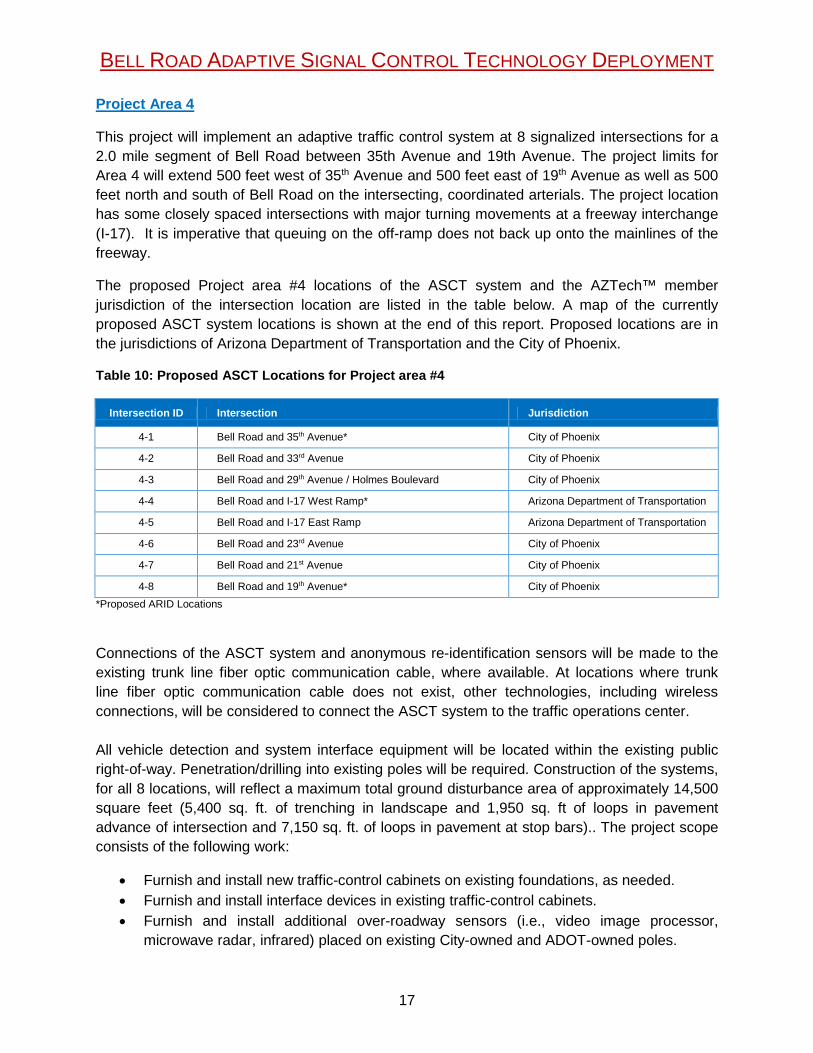
Project Area 4 contains six signals operated by the City of Phoenix and two signals operated by ADOT, for a total of eight signals. The priority in Project Area 4 was to improve progression of traffic across the I-17 freeway interchange, without negatively impacting the freeway ramps, and without over extending city staff efforts.
The new timing plans estimated by the system are saved and, over time, the system can determine a new baseline timing plan based on historical needs.
The splits, offsets, cycle lengths, and phase sequences are calculated and updated each second, enabling this “true” real-time adaptive system to have different timing each cycle.
Bell Road ASCT Comprehensive Study
Prepared for: Maricopa County Department of Transportation
AECOM 17
The ASCT software chosen was the TransCore ACDSS in collaboration with KDL Engineering. Similar to the system in Project Area 1, this is a centralized, software-only system that does not require field hardware. New lane-by-lane detection was installed as part of this project. This system requires input signal timing plans and can use immediate historical data to determine the most appropriate timing plan at the moment. Timing plans are re-evaluated every several cycles. It should be noted that, because historical data is used as opposed to real-time
data, the signal timings cannot be adjust for pedestrian calls immediately as they’re made. Because of this, the City of Scottsdale has currently turned their ASCT system off, requiring more time to work with the vendor for a solution. The City of Phoenix has also turned their system off at this time, and will be re-evaluating with the vendor for the best practice moving forward.
5. Best Practices for ASCT Implementation
This pilot program focused on implementation of ASCT on three distinct and geographically separated segments of Bell Road. This implementation is meant to inform future ASCT projects in Maricopa County and other areas. As such, the challenges facing the ASCT conversion and lessons learned from implementation are identified here.
5.1 Challenges to implementation
Every ASCT deployment is intended to improve signal operations, thereby improving arterial mobility. However, each deployment comes with additional challenges unique to the region or agency. Several challenges to deployment of ASCT on Bell Road in Maricopa County are identified here.
Multiple Agencies – Bell Road is a corridor that traverses several city and town jurisdictions, with traffic signals operated by multiple agencies. As one of the few east-west corridors in the region with access across the Agua Fria River, it is not uncommon for a commuter to travel through multiple cities in a single trip without leaving Bell Road. Each agency involved had specific goals, as identified above.
Network Communications – Challenges with the communication network for implementing a distributed system arose during implementation but were overcome by utilizing the Maricopa Association of Governments (MAG) Regional Community Network (RCN). The RCN is a private internet connecting agencies in Maricopa County to share traffic and public safety information. This shared community network was implemented several years prior to this project for the advancement of ITS in the region. The connection uses existing agency-owned fiber in combination with wireless links to bridge gaps in fiber connectivity. For this project, the RCN was used for communication across agency firewalls and networks.
Traffic Signal Hardware and Detection Systems – With any ASCT deployment, the adaptive signal operations are only as good as the detection. Each agency was responsible for the signal hardware in their project area, and ensuring that signal hardware was compatible with the adaptive system chosen. The committee decided early on that detection systems would need to be sourced in parallel with the ASCT system.
Because historical data is
used as opposed to real-time data, the signal timings cannot be adjusted for pedestrian calls immediately as they’re made.
Bell Road ASCT Comprehensive Study
Prepared for: Maricopa County Department of Transportation
AECOM 18
Differential Procurement for Software and Detection – The committee determined that ASCT system and detection system should be procured separately. The software was procured using a Request for Qualifications (RFQ), in which the system administrators and software were chosen based on their ability to fulfill the needs of the agency. The detection installation, however, was chosen from a low-cost bid. The decision brought forth two challenges to the team: 1) the detection installation team was not necessarily fully informed of the needs of the ASCT system, resulting in the need for mediation between the ASCT operator and the installation group, although detailed layouts were provided as part of the procurement; and 2) the agency staff was not necessarily familiar with the detection system, leading to a learned curve for understanding the system needs.
5.2 Post-Project Interviews
At the time that the ASCT system installments were completed and each project area had some experience with operations, a survey was conducted to ascertain the relevant experience of the agency staff throughout the process. The survey instrument and original responses from the agencies are included in Appendix A. Five of the seven agencies involved in the pilot program returned survey responses, including at least one agency from each project area, with the exception of Project Area 3. The survey questions were a mix of closed-response Likert scale responses and open essay-style responses.
A summary of responses to the Likert scale closed-response questions is provided in Table 1. Each question was posed on a 5-point scale, with 1 being the least positive response and 5 being the most positive. Note that overall, the response to the ASCT systems from the perspective of the agency partners has been very positive. The exception is the experience of Project Area 4 as it relates to the detection system.
The detection system used in Project Area 4 includes dome cameras for stop bar detection and other cameras for advance detection, resulting in some intersections with up to five cameras. This number of detection devices created issues for the City of Phoenix. Additionally, the ARID devices created some challenges for the Project Area 1, in that the devices experienced connection issues and ultimately had to have components replaced. In the end, however, the agencies agree that the public feedback has been positive overall.
Overall, the responses to the ASCT system from the perspective of the agency partners have been positive.
Bell Road ASCT Comprehensive Study
Prepared for: Maricopa County Department of Transportation
AECOM 19
Table 1: Responses to Likert Scale Survey Questions
No. Question
Project Area
1
Response*
Project Area 2
Average
Response
Project Area
4
Response*
Overall
Average
Response Notes
2 I feel the detection devices selected allowed
us to get full use from the adaptive signal
system chosen.
4.0 4.7 2.0 4.0 Project Area 1 partner was familiar with the
chosen detection system while Project Area 4
partner was not.
3 How would you rate the user interface of the
adaptive signal system? Is it intuitive and
easy to use?
5.0 4.0 3.0 4.0
4 How would you best describe the public
feedback after implementation? 4.0 4.0 4.0 4.0
9 Rate your satisfaction with the following adaptive signal technology categories in your jurisdiction
9a Procurement of System 3.0 4.0 1.0 3.2
Project Area 4 partner was given no choice of
detection by their vendor.
9b Installation of System 4.0 4.3 2.0 3.8
In Project Area 4, the detector system
scheduling and set-up was poor.
9c
Technology: Detectors 5.0 4.0 1.0 3.6 In Project Area 4, the project selected use of a
dome camera, resulting in 3 cameras on 1 riser
in some locations.
9d Technology: Software 5.0 5.0 5.0 5.0
9e
Technical Support Helpfulness 5.0 5.0 3.0 4.6
The Rhythm system in Project Area 2 requires
that all issues go through their maintenance
department, in exchange for full customer
support 24/7 while under contract.
9f Operation of System 5.0 5.0 3.0 4.6
Project Area 1 partner already had a
relationship with its vendor.
9g ARID Devices 2.0 4.3 3.0 3.6
The ARID devices had connectivity issues and
had to be replaced. Support was inconsistent.
9h Maintenance of System 4.0 4.3 3.0 4.0
9i Overall Cost of System 5.0 3.7 3.0 3.8
10 Was the System Engineering process
completed before the design/procurement
stage helpful for the project?
5.0 4.7 ** 4.8
*This column contains responses from only one agency partner **Responder was not part of the project at the time of the Systems Engineering process
Bell Road ASCT Comprehensive Study
Prepared for: Maricopa County Department of Transportation
AECOM 20
The survey solicited open-ended responses to several questions in order to obtain a more overall qualitative evaluation of agency partners’ experiences. One of the survey responses did not include answers to the open-ended questions, resulting in a total of four responses for each question. The responses to those open-ended questions are summarized below.
1. What was the primary goal of your agency for deploying adaptive signal technology?
The agencies in Surprise, Peoria, and Glendale indicated that their primary focus was to improve throughput, travel times, and/or congestion in a typical day along the corridor. The agencies in Phoenix and Peoria also identified the need to coordinate traffic signals at freeway interchange traffic signals operated by ADOT. In the past, signal coordination between freeways and arterials were a struggle because of different signal timing approaches. Though not indicated in this survey, in-person interviews with the different agency partners also reveal that operations under special event traffic was a priority on Project Area 1 and Project Area 3, and that seasonal traffic changes – especially holiday shopping traffic – was a priority on Project Area 2.
5. What were the top three challenges your agency faced during deployment of adaptive signal systems?
The challenges reported include:
• Staff training and knowledge retention
• Understanding how to retain the city’s own detection system in addition to the ASCT’s detection system, in the event the ASCT detection fails
• Demands on the city staff’s time to get the system and detection set up
• The need to upgrade old standards of cabinets to a larger size in order to accommodate the system
• The need to upgrade radio communications
• Difficulty scheduling a time with the vendor to correct detection problems
• Issues with the lack of available right-of-way needed to fit devices and cabinets that needed to be upgraded to accommodate the needs of an ASCT system.
• Reporting issues between the detectors, the controllers, and the software
6. What were the top three benefits your agency received from deploying adaptive signal systems?
The benefits reported include:
• The opportunity to upgrade the intersection systems, especially the detection systems
• System accommodates changes in travel patterns without the need for a new coordination plan
• Consistent coordination across jurisdictions
• The system is very “hands-off” and does not require constant attention from city staff, especially in the context of seasonal adjustments
• The customer service is great (from an agency in Project Area 2)
This pilot project provided the opportunity to upgrade the intersections, especially the detection systems.
Bell Road ASCT Comprehensive Study
Prepared for: Maricopa County Department of Transportation
AECOM 21
• Bell Road travel times are reduced with little impact to the intersecting side streets
• Count data is stored in the detectors, and can be accessed for other analyses (from an agency in Project Area 4)
• The system now recovers much more quickly from unexpected congestion events
• Travel times and stops between intersections have been reduced
7. Does the adaptive signal software record useful data regarding the operations of the signal? What data do you find more useful?
The partner agencies reported that the adaptive systems can store data on all timing changes, the time given to each cycle or period, and other signal operation metrics. The City of Phoenix also highlighted the ability to store traffic counts in the detector system, which is useful for other applications of traffic engineering and planning.
8. Would you recommend this pilot adaptive system to be expanded to additional intersections in your jurisdiction?
All respondents indicated that they would like to expand ASCT to other areas in their jurisdictions. MCDOT and the City of Surprise are both currently in the process of implementing ASCT in other
corridors. The City of Peoria emphasized that the ASCT would be especially helpful in other areas where a corridor crosses jurisdictional boundaries. The City of Phoenix emphasized that adequate detection would be needed in other areas in order to effectively implement.
11. What are the biggest lessons learned from this pilot project? What should have been done differently?
Three of the respondents completed this question prompt, and all three respondents reported lessons learned centered on detection systems. The City of Peoria said that detection systems and software systems should go together as a team, or the vendor should be chosen first and recommend what detection to implement, as was done with this project. The City of Phoenix said they would have preferred the pilot project use their own technicians for installing the detection. Finally, the City of Surprise said they did not have enough knowledge of how results could vary with different detection configurations prior to selecting the vendor.
5.3 Lessons Learned
As this project is meant as a pilot to test the use of ASCT on multi-jurisdiction corridors, several lessons learned were identified as a result of this deployment. Interviews with the agency partners and a survey questioning their experiences revealed some key points to be considered in the future deployment of such a system.
Preliminary Engineering is Key – Agency partners all agreed that an extensive amount of time was spent on the preliminary Systems Engineering aspect of this project, and that the smooth deployment of the system was entirely due to that pre-work. Partners agreed that ASCT is not appropriate for every situation, and that it is extremely important to thoroughly assess whether it will be the best choice on a case-by-case basis. The Concept of Operations documents
ASCT is especially
helpful in areas where a corridor crosses jurisdictional boundaries.
Adequate vehicle detection is needed to effectively implement ASCT
Bell Road ASCT Comprehensive Study
Prepared for: Maricopa County Department of Transportation
AECOM 22
produced for each project area provided a thorough blue print for the procurement and implementation of each project area’s individual systems that can be used on future projects. Having realistic expectations for the ASCT system, well-defined objectives, and goals are keys to a successful preliminary engineering effort.
ASCT Software and Detection Should Go Together – The process adopted in this project was to submit an RFP for an ASCT software vendor, then confer with that vendor to determine the best detection configuration, and solicit a low bid for installation of the detection. Upon reflection, agency partners agreed that this procedure resulted in complications. In most instances, there was difficulty in the vendors detection needs being met and understood by the detection installation contractor. One alternative option for procurement that agency partners would suggest is a contract similar to a Construction-Manager At Risk (CMAR), or one in which the vendor and the contractor work as a team from the start.
Budget for Communication Upgrades – In this pilot project, a majority of the resources were centered on detection, as it is key for successful deployment of any signal timing strategy. It was assumed that the communication connections along the corridor would be sufficient to meet the needs of the ASCT. In this instance, the Maricopa Association of Governments (MAG) provided communication infrastructure which the BRCC members had already tied into. If that infrastructure was not already available, the distributed ASCT system would not have been possible.
Keep Non-Motorized Traffic in Mind – In the case of Project Area 3, special events come with quite a bit of non-motorized pedestrian travel. In this project area in particular, the vendor and the City were not able to work through what was needed to accommodate pedestrian traffic while maintaining a high level of corridor progression, and the system was turned off.
Seek Training on Traffic Detection Configurations – At least one of the agency partners identified a lack of knowledge of detection configurations prior to the selection of an ASCT vendor as their number one lesson learned in this project. This was a lesson learned for the city overall, but became apparent during the ASCT implementation, because detection is so vital to the system. Detection results can vary dependent on the type and positioning of devices. An in-depth knowledge of those varying outcomes could better inform the selection team during procurement. Regional Collaboration and Champions – The success of this project was derived from the collaborative spirit of the partner agencies. The fact that the Bell Road Coordination Committee was formed and meeting regularly at the time of this project’s inception meant that issues had already been identified and relationships among the team members were already established. Maricopa County’s strong leadership in securing the funding for the project provided a focal point for branching policy perspectives. In project areas with staff turnover related to this project, and no longer having a champion for the project, leadership was not available to produce a successful project.
6. Operational Results
In order to assess the outcomes of the implementation of ASCT along Bell Road, operational metrics were collected and compared before and after implementation. In this section, the
Agency partners would suggest a contract similar to a CMAR, or one in which the vendor and the contractor work as a team from the start.
Bell Road ASCT Comprehensive Study
Prepared for: Maricopa County Department of Transportation
AECOM 23
operational metrics are provided for several time frames, times of day, and locations in order to assess the overall picture of the effects of this technology.
6.1 Methodology
The travel time data along Bell Road for several years of historical data is available in the INRIX data, which was accessed in this assessment using the RITIS online system. The ADOT INRIX contract was used to help gather data. Because there are so many possible configurations of data assessment through the RITIS system, a methodology memorandum was submitted prior to this report, and is available in Appendix B.
The source of the data used for this evaluation is INRIX, made available through the RITIS online system. INRIX data is gathered from smart phone GPS and location-based application data. As stated previously, the ASCT systems in Project Areas 3 and 4 – the City of Scottsdale and the City of Phoenix, respectively – have been deactivated in order to re-assess the timing plans, and to meet the needs of pedestrians. As such, the data included here is not necessarily representative of the current traffic conditions. For each of the project areas, performance metrics are calculated for the length of the project area, for at least one smaller sub-area within that project area surrounding an attraction or significant interchange, and for a cross road. Additionally, metrics are provided for an average weekday, weekday peak periods, an average weekend, weekend peak period, and in some cases during special event or seasonal travel time frames.
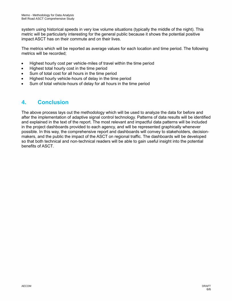
The metrics that are gathered for each project area and time period reflect both the traffic operations and the resulting cost of operations. Travel time, speed, travel time index, and planning time index are provided to assess the operations.
6.2 Results
The following sections present the results of the before and after analysis on an area-by-area basis per the project areas identified in Figure 3Error! Reference source not found.. Within the context of this report, “before” refers to the time period immediately before implementation of ASCT, and “after” refers to the time period after ASCT was implemented. The results presented in the following sections are summarized in tables as user cost saved and as percent reduction in delay and travel time as well as percent increase in speed. Note that a negative value for any of these metrics indicates a trend that is opposite from what is desired. The results within the body of the report represent a summary of the most significant trends seen, as opposed to all data that was parsed for this analysis. Complete details of data comparing before and after conditions are available in Appendix C.
6.2.1 Project Area 1 – Cotton Lane to 114th Avenue
Overall Project Area 1 Results The implementation of ASCT in Project Area 1 resulted in some improvement. Overall, traffic operations improved most significantly during weekday mid-day and PM peak hours and weekend mid-day peak hours, but also showed improvement during weekday AM peak hours and special events at Surprise Stadium. Table 2 presents the results for average weekdays, average weekends, and special events for Project Area 1.
On average, weekday travel times through the project area decreased by 2%, in which the largest improvement occurred during the mid-day peak hours. After the ASCT installation, delay decreased by 1,000 hours on an average weekday, a 20% reduction in delay time, and a cost benefit to roadway users of over $9,000/day. Weekend travel times through the project area decreased by 2.3% and delay decreased by 43.6%. The cost benefit to roadway users during
Bell Road ASCT Comprehensive Study
Prepared for: Maricopa County Department of Transportation
AECOM 24
the weekend is almost $10,000/day. During special events there was a 5% decrease in travel time for users along Project Area 1 and delay decreased by 38.7%.
Table 2: Project Area 1 Results Summary
Average Weekday Average Weekend Special Event
User Cost Saved/Day $9,270.98 $9,758.06 $1,437.36
Reduction in Delay 20.3% 43.6% 38.7%
Reduction in TT 2.0% 2.3% 5.1%
Increase in Speed 2% 2% 5%
Figure 4: Project Area 1 Weekday Travel Time
Bell Road ASCT Comprehensive Study
Prepared for: Maricopa County Department of Transportation
AECOM 25
Figure 5: Project Area 1 Weekend Travel Time
The priority in Project Area 1 was to address special event traffic in addition to improving typical daily travel. Compared to other time periods in this project area, the results during special events show the second largest percent reduction in delay, the highest percent reduction in travel time and the highest increase in speed. These results show that the priority for this segment was met by the ASCT system that was installed.
Crossroad Results – Litchfield Road and Grand Avenue Litchfield Road and Grand Avenue near Project Area 1 were analyzed to gauge the effect of ASCT on crossroads. On Litchfield Road, travel times increased by less than 1% during the weekday and weekends. Delay also increased slightly on Litchfield Road during the weekday and weekends. While the increased travel time is less than ideal, this negative effect is minimal on the crossroad, compared to the improvements seen on Bell Road.
6.2.2 Project Area 2 – 99th Avenue to 73rd Avenue
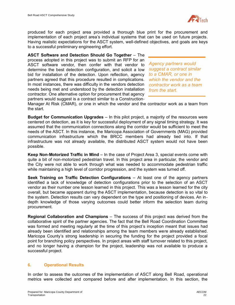
Overall Project Area 2 Results The implementation of ASCT in Project Area 2 resulted in significant improvement, especially from 9:00 AM to 6:00 PM. Overall traffic operations improved most significantly during weekday peak hours, but also showed improvement during weekends and non-peak hours. Special events traffic caused by the Peoria Sports Complex saw a slight increase in travel time but also saw a reduction in overall delay, indicating a more consistent flow through the corridor at a slightly lower speed. Table 3 presents the results for average weekdays, average weekends, and special events for Project Area 2.
On average, weekday travel times through the project area decreased by 11.5%, in which the largest improvement occurred during the PM peak hours. After the ASCT installation, delay decreased by 2,800 hours on an average weekday, a 51% reduction in delay time, and a cost benefit to roadway users of nearly $26,000/day. Weekend travel times through the project area decreased by 1.5%, and delay decreased by 7%. The cost benefit to roadway users during the weekend is around $1,600/day. During special events there was a 21 second increase in travel time for users along Project Area 2, but delay decreased by 18%. This indicates that, though speeds are very slightly slower overall, vehicles make fewer stops.
The results during special
events show the second-largest reduction in delay in this project area.
Bell Road ASCT Comprehensive Study
Prepared for: Maricopa County Department of Transportation
AECOM 26
Table 3: Project Area 2 Results Summary
Average Weekday Average Weekend Special Event
User Cost Saved/Day $25,925.44 $1,639.80 $865.59
Reduction in Delay 51.4% 7.0% 16.7%
Reduction in TT 11.5% 1.5% -5.3%
Increase in Speed 10% 2% 0%
Figure 6: Project Area 2 Weekday Travel Time
Bell Road ASCT Comprehensive Study
Prepared for: Maricopa County Department of Transportation
AECOM 27
Figure 7: Project Area 2 Weekend Travel Time
Between all the project areas, Project Area 2 showed the most improvement on typical weekdays. One factor that may have caused this is that compared to the other project areas, the ASCT system for Project Area 2 uses software that contains the most adaptive and aggressive signal features. This fully adaptive system may prove to be more effective at servicing the needs of the project area based on real-time needs rather than historical data.
In addition to focusing on typical daily travel, the priority in Project Area 2 was to improve traffic flow during special events and holiday shopping. Compared to other time periods for this project area the results for special events show the second highest reduction in delay while travel time actually increased and speeds remain about the same. There may be opportunity to further refine the adaptive system to better meet the goals for this project area.
Crossroad Results – 83rd Avenue 83rd Avenue near Project Area 2 was analyzed to gauge the effects of ASCT on crossroads. On 83rd Avenue, travel times decreased by 1% during the weekday and increased by 2% on during weekends. Delay decreased by 42% on the weekdays and increased by 66% on the weekends. User cost decreased by over $2,000 on weekdays and increased around $1,800 on weekends. In all, the effect on cross road traffic has been minimal, and has been slightly beneficial for weekday travel.
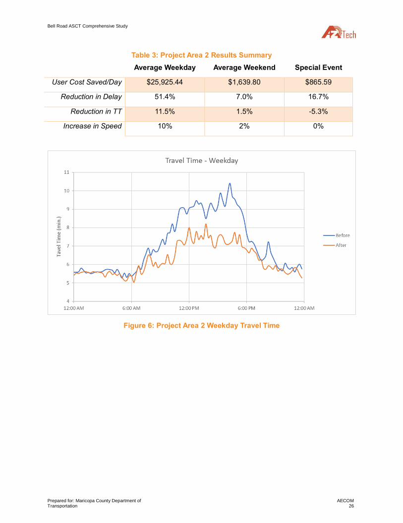
Bell Road and 99th Avenue ATSPM Data Project area 2 has the benefit of continuous Automated Traffic Signal Performance Measures (ATSPM) monitors. Purdue phase coordination diagrams were pulled from the ATSPM network at the representative intersection of Bell Road and 99 th Avenue on a typical weekday (Thursday, Feb. 1, 2018) after the implementation of the ASCT. The diagrams are provided in Figure 8. The diagrams show that in the eastbound direction in the AM and PM peak hours, 92% and 90% of vehicle arrive at the intersection when the phase is green, respectively. In the westbound direction, the arrivals on green in the AM and PM peak hours are 88% and 82%, respectively.
This full adaptive system may prove to be more effective at servicing the needs of the project area based on real-time demand.
Bell Road ASCT Comprehensive Study
Prepared for: Maricopa County Department of Transportation
AECOM 28
The Purdue Coordination diagrams show the adaptive nature of the system, with variations in the phase occurring at each cycle.
Figure 8: Purdue Phase Coordination
6.2.3 Project Area 3 – Scottsdale Road to Thompson Peak Parkway
Overall Project Area 3 Results In Project Area 3, as noted previously, the corridor that is continuous with Bell Road curves slightly to the southeast and is named Frank Lloyd Wright Boulevard. The implementation of the ASCT in Project Area 3 generally improved operations during the weekends and increased travel times during the weekday. Table 3 presents the results for average weekdays, average weekends, and special events for Project Area 3.
The AM and PM peak hours on weekdays both experienced an increase in travel time by 1.5% and 13.4%, respectively. For the average weekday, delay increased by 13% in the AM Peak and
Bell Road ASCT Comprehensive Study
Prepared for: Maricopa County Department of Transportation
AECOM 29
by 86.6% in the PM Peak, but decreased by 2% in the Mid-Day. Overall, delay and the associated user cost both increased for the average weekday and decreased for the average weekend. On the average weekend, delay was decreased by 12.9% during the mid-day peak and by 31.3% for the entire weekend day.
One of the major special events occurring annually along this segment is the Waste Management Open golf tournament The tournament typically hosts events which last one week at the end of January, from Monday through the following Sunday. The majority of spectator activity, however, takes place on the Friday-Sunday of the tournament. The ASCT system in Project Area 3 was initiated in January, 2018. However, the system was suspended during the peak spectator times of the tournament. The special event evaluation for this project area therefore takes place on the Thursday of the 2017 tournament (the “before” evaluation) and the Thursday of the 2018 tournament (the “after” evaluation) from 12:00 to 2:00 PM. Using this time frame as a metric, the ASCT system reduced travel time during special event by 6.6% and reduced overall user by 23.3%.
Table 4: Project Area 3 Results Summary
Average Weekday Average Weekend Special Event
User Cost Saved/Day -$5,924.48 $2,666.35 $1,169.48
Reduction in Delay -42.7% 31.3% 23.6%
Reduction in TT -1.1% 4.0% 6.6%
Increase in Speed 0.3% 3.5% 5.3%
Figure 9: Project Area 3 Weekday Travel Time
Bell Road ASCT Comprehensive Study
Prepared for: Maricopa County Department of Transportation
AECOM 30
Figure 10: Project Area 3 Weekend Travel Time
The priorities for Project Area 3 were to improve flow during heavy vehicle and pedestrian peak weekday travel times, in addition to addressing special event traffic. Although the system was not tested during the largest volume special event traffic, the data that was available showed an improvement in special event traffic flow. On the other hand, the goal of improving vehicle and pedestrian traffic during peak weekday travel times was not met. This system’s reliance on historical data may have been a detriment to its responsiveness to cycle-by-cycle traffic and pedestrian activity changes. The ASCT system in this project area was turned off in order to better address the needs of the corridor. The agency partner in Project Area 3 is currently working with its vendor to improve responsiveness and eventually re-start the system.
Crossroad Results – Greenway-Hayden Loop The Greenway-Hayden Loop road intersections with Frank Lloyd Wright Boulevard in Project Area 3, and is also an access route to the TPC Scottsdale golf course. On this crossroad segment, travel times were generally increased and speeds decreased on typical weekdays by 4.2% and by 3.3%, respectively. The total vehicle-hours of delay on this crossroad segment increased by 120% for the typical weekday. On a typical weekend day, the average travel time and speed remained nearly the same, with very little change to delay and user cost.
6.2.4 Project Area 4 – 35th Avenue to 19th Avenue
Overall Project Area 4 Results The implementation of ASCT in Project Area 4 generally improved traffic operations during the off-peak hours and on weekends, while slightly increasing average travel times during the weekday AM and PM peak hours, as shown in the figures below. For an average weekday, delay increased during the AM and PM peak hours by 36% and 5%, respectively, but was reduced by 27% during the mid-day peak hours. Overall, delay and the associated user cost both increased for the average weekday and decreased for the average weekend after the implementation of ASCT in this project area. Average speed and travel times were improved for both weekdays and weekends. Table 5 summarizes the data for Project Area 4. On the weekday, the overall increase in speed combined with the increase in delay could indicate that vehicles are stopping fewer times than before the ASCT implementation, but waiting longer at
The goal of improving
vehicle and pedestrian traffic flow during peak weekday travel times was not met.
Bell Road ASCT Comprehensive Study
Prepared for: Maricopa County Department of Transportation
AECOM 31
that stop. However, because Project Area 4 is significantly shorter than the other project areas, and travel times are generally less, one small magnitude changes in travel time or delay will reflect larger percentage changes, as compared to the other project areas.
Table 5. Project Area 4 Results Summary
Average Weekday Average Weekend
User Cost Saved/Day -$318.05 $356.94
Reduction in Delay -4.6% 16.1%
Reduction in TT 1.9% 1.9%
Increase in Speed 2.3% 1.9%
Figure 11. Project Area 4 Weekday Travel Time
Bell Road ASCT Comprehensive Study
Prepared for: Maricopa County Department of Transportation
AECOM 32
Figure 12. Project Area 4 Weekend Travel Time
The priority in Project Area 4 was to improve progression of traffic across the I-17 freeway interchange, without negatively impacting the freeway ramps and exerting extra staff resources. The results for this project area show an overall increase in user costs and an increase in delay on the average weekday. The system used in this project area does not appear to be meeting the priority of this project area. Since this data was collected, the Project Area 4 ASCT system has been de-activated, in order to adjust and improve operations, which may improve results in the future.
Crossroad Results – Black Canyon Frontage Road Southbound from I-17 Exit to I-17 Entrance The analysis results for this cross-street segment were the inverse of the results for the main Project Area 4: the frontage road operations improved during the peak hours and degraded during the off-peak and weekend hours after ASCT implementation. Total delay through the segment was reduced by 42% and 43% during the AM and PM weekday peak hours, respectively, and by 27% overall for an average weekday. In contrast, the delay was increased by 68% during the mid-day weekend peak hour and by 113% for the entirety of the average weekend.
The reduction of delay during the average weekday was accompanied by a 10% increase in travel time through the corridor during the same period. This shows that although on average it took 10% longer to traverse this short segment of the frontage road, a smaller number of vehicle hours were spent at more than 5 mph below the free-flow speed. In other words, the implementation of the ASCT system decreased average travel times, but also reduced the amount of severe congestion during an average weekday in the segment.
Crossroad Results – Black Canyon Frontage Road Northbound from I-17 Exit to I-17 Entrance The implementation of the ASCT system in this segment reduced delay most during the PM weekday peak hour and the mid-day weekend peak hour, when delay was reduced by 29% and 79%, respectively. In all other time periods analyzed, delay, travel time and user costs each
On the cross-street, the ASCT implementation decreased average travel times, and also reduced the amount of severe congestion during average weekdays.
Bell Road ASCT Comprehensive Study
Prepared for: Maricopa County Department of Transportation
AECOM 33
increased through this segment while average speeds decreased. The northbound frontage road did not see the same benefits during the average weekday as the southbound frontage road. Delay and user costs for the average weekday on this segment increased by 35%, with a 21% decrease in speed and a 27% increase in travel time. One must note, however, that – like the Bell Road segment itself, this crossroad segment is a short length with shorter travel time as compared to other segments. Small magnitude changes will therefore reflect larger percent changes than the other segments.
7. Conclusion
Segments along the Bell Road corridor had a variety of ASCT systems. Each system yielded some benefits although some provided more board ranging benefits and others were more targeted. Overall, the project resulted in some valuable lessons learned that can be applied to future implementation of ASCT systems.
Each project area had distinct priorities. The system installed in Project Area 1 appears to be meeting the priorities of that project area by demonstrating improvement during typical daily travel as well as special events. Project Area 2’s system resulted in the best overall improvement during the average weekday, but appears to have room for improvement in meeting the special event travel expectations. Some adjustments to the ASCT system in Project Area 2 may allow it to better meet the priorities of that project area. Implementation of event triggering sensors in coordination with the ASCT system to turn on the special event timing considerations may also benefit this area. The system in Project Area 4 was intended to improve progression of traffic across the I-17 freeway interchange, however it does not appear to be meeting that goal during the average weekday.
Overall, the partner agencies expressed satisfaction with the operational outcomes of the ASCT implementation. The data provided here may give some project areas the information needed to further enhance their systems and achieve more desirable results. Each partner agency agrees that they would recommend the implementation of ASCT for other select corridors, both in their own jurisdictions and those of their neighbors. Please note, however, that ASCT systems are not advised to be installed at every traffic signal. A systems engineering process should occur to help determine if an ASCT system can be beneficial on a case-by-case basis.
Moving forward, it is recommended that the signal performance of this pilot program be monitored so that any performance issues can be quickly identified and resolved with the corresponding vendors or detection systems. Aside from the typical daily monitoring that occurs in all agencies to check for major issues, the signals should be evaluated quarterly for performance compared to the respective agency standards. Average travel speed and delay in each project area should be compared against neighboring parallel corridors which do not employ ASCT. If the Bell Road corridor has greater delay per vehicle or much lower travel speeds than the corridor not employing ASCT over a two week time period, then making adjustments to the ASCT system should be considered to enhance performance. Another consideration could include reverting to time-of-day plans. Because ASCT systems are adaptable to seasonal changes in traffic, it is not anticipated that the system will need to be adjusted for every seasonal change.
Each partner agency agrees that they would recommend the implementation of ASCT for other select corridors, both in their own jurisdictions and their neighbors’.
Bell Road ASCT Comprehensive Study
Appendix A Survey Instrument and Reponses
Bell Road Adaptive Signal Control Technology (ASCT) Comprehensive Study
Category Satisfaction Number Additional Comments Procurement of System Installation of System Technology: Detector Technology: Software Technical Support Helpfulness Operation of System ARID Devices Maintenance of System Overall Cost of System
Right-of-way issues limited the ability to install equipment on certain poles.
There were reporting issues between the detection, controller and adaptive software.
After the system was deployed and made active, the corridor was able to recover fromunexpected congestion much quicker than in the past.
Initial tests have shown that travel times and stops have reduced.It has allowed for more of a "hands-off" approach in handling the changing seasonal traffic patterns.
Several parameters are retained. All timing changes, detector usage and AOG/AOR are all kept and available.
Yes, we are currently looking into candidate corridors.
Staff training and knowledge of the system. Since we only have 3 signals running adaptive, staff gets into the system rarely causing knowledge retention issues.
wirea
Typewriter
Detection system upgrade
wirea
Typewriter
Being able to accommodate changes in travel patterns and volumes without having to create new coordination plans.
wirea
Typewriter
Consistent cross jurisdictional signal coordination
wirea
Typewriter
The historical log allows you to see how much time is given each cycle/period.
wirea
Typewriter
Yes - MCDOT plans on adding the 2 signals to the west on Bell Rd in FY 20. There has also been conversations about expanding the ASCT network in the west valley region.
wirea
Typewriter
3
wirea
Typewriter
4
wirea
Typewriter
3
wirea
Typewriter
5
wirea
Typewriter
5
wirea
Typewriter
5
wirea
Typewriter
3
wirea
Typewriter
5
wirea
Typewriter
3
wirea
Typewriter
Long duration - treated like typical construction project with clearances
wirea
Typewriter
The vendor had a sub that did all the installation and setup, including the configuration of the detection.
wirea
Typewriter
Vender's sub installed the detection and configured it.
wirea
Typewriter
Vendor did a great job and going over the details of the software and the values on the user interface. The software is fairly intuitive.
wirea
Typewriter
24-7 support for 5 years as part of the project
wirea
Typewriter
Acyclica was able to provide the region with access to all of the regional data. Devices should have been installed before the system went in.
wirea
Typewriter
24-7 support for 5 years
wirea
Typewriter
All the systems were similar but Rhythm's system included detection which makes it a bit cheaper overall.
10. Was the system engineering process completed before the design/procurement stage helpful for
Some of the system requirements given by FHWA seemed repetative. During the acceptance testing, partners had difficulty remember which each requirement entailed.
wirea
Typewriter
See attached
wirea
Typewriter
How did each system satisfy each agency's goal, in what scenarios would the agency recommend their ASCT system, next steps for the region, matrix of features?
Bell Road Adaptive Signal Control Technology (ASCT) Comprehensive Study
11. What are the biggest lesson(s) learned from this Pilot Project? What should have been done
differently?
The pilot should have used COP technicians not outside parties or vendors to trouble shoot
detection.
12. What information would be most helpful for you to see in the before and after study?
1. Actual travel time reduction during peak traffic
2. Coordination of signals between agencies
3. Arrivals on green
4. Arrivals on red
5. Delay metrics
6. Level of service
7. Environmental impact
8. Cost benefit analysis
9. Evaluation and analysis
10. Lessons learned
Bell Road ASCT Comprehensive Study
Appendix B Methodology Memorandum
DRAFT 1/6
To: Maricopa County Department of Transportation April Wire, P.E., P.T.O.E. Arterial Operations Program Manager Intelligent Transportation System Branch [email protected]
AECOM 7720 North 16th Street Phoenix, AZ 85020 aecom.com
Project name: Bell Road ASCT Comprehensive Study
Date: June 26, 2019
Memo
Subject: Methodology for Data Analysis
1. Introduction
Bell Road is a major arterial corridor traversing across the Phoenix Metropolitan Area in the east-west direction. The roadway crosses several jurisdictions and intersections along the corridor are controlled by several different agencies, including the cities of Surprise, Peoria, Glendale, Phoenix, and Scottsdale, the Arizona Department of Transportation (ADOT), and the Maricopa County Department of Transportation (MCDOT). The length and position of Bell Road makes it an important commuter corridor, and as such it can experience congestion. In fact, Bell Road has the highest traffic volumes of any arterial roadway in Arizona. In order to best serve the Bell Road travelers, the agencies along the corridor collaborated to transition the traffic signals to Adaptive Signal Control Technology (ASCT) in four localized Project Areas. A comprehensive study has been commissioned in order to document the history of the project, the process of transitioning the signals to ASCT, lessons learned, and analysis of performance data both before and after the transition.
The purpose of this memorandum is to detail the process of data analysis for corridor performance both before and after the transition to ASCT.
2. Data Sources
ADOT has contracted with RITIS to receive INRIX analytic data on major roadways in Arizona. ADOT and RITIS have provided access to probe diagnostic data to all interested jurisdictions within Arizona. These probe diagnostics are gathered through smartphone GIS and location-based applications, which can be tracked against time to gather speed and travel time data along the corridor. Several years of past data are available in these diagnostics. In addition, delay can be calculated as the experienced travel time compared to free-flow travel time, and monetary values of time can be applied to this delay to understand the cost savings associated with the project.
In addition to the probe data analytics, volumes along the corridor that were historically collected by the various stakeholder agencies will also be collected to further analyze and correlate how traffic volumes have had an impact on travel time.
Memo - Methodology for Data Analysis Bell Road ASCT Comprehensive Study
AECOM
DRAFT 2/6
3. Data Analysis Methodology
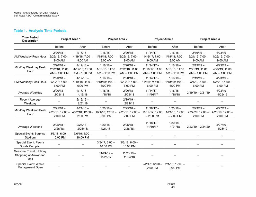
The remainder of the document will be dedicated to detailing the methodology for analyzing the corridor analytic data. Several locations for analysis have been identified, both along Bell Road and on crossing arterials. Days and times for analysis are also identified herein. Lastly, the metrics that will be collected for each specific time and location are identified.
3.1 Analysis Locations
The Bell Road corridor for this project was broken into four project Areas, each corresponding to a different ASCT software vendor and detector system. Each Project Area began operating ASCT at a different time. Analytics will be run for each Project Area as a whole in both the eastbound and westbound directions. In addition, within each Project Area several smaller segments will be identified for diagnostics runs both along the Bell Road corridor and on cross streets with a relatively higher traffic volume demand. The locations chosen are as follows: Project Area 1
Entire project area length ─ Bell Road from Cotton Lane to 114th Avenue
Sub-Area Segments ─ Surprise Stadium area: Bell Road from Reems Road to Litchfield Road ─ Grand Ave area: Bell Road from Litchfield Road to Dysart Road
Cross Street Locations ─ Surprise Stadium area: Litchfield Road from Bell Road to Greenway Road ─ Grand Ave area: Grand Avenue from Litchfield Road to Dysart Road
Project Area 2
Entire project area length ─ Bell Road from 99th Avenue to 73rd Avenue
Sub-Area Segment ─ Peoria Sports Complex and Arrowhead Mall area: Bell Road from SR 101L to 75th Avenue
Cross Street Locations ─ Peoria Sports Complex area: 83rd Avenue from Union Hills Drive to Thunderbird Road
Project Area 31
Entire project area length ─ Frank Lloyd Wright Boulevard from Scottsdale Road to Thompson Peak Parkway
Sub-Area Segment ─ Scottsdale Airport area: Frank Lloyd Wright Boulevard from Greenway-Hayden Loop to
Hayden Road
Cross Street Locations: ─ Greenway-Hayden Loop from Scottsdale Road to Bell Road
Project Area 41
Entire project area length ─ Bell Road from 35th Avenue to 19th Avenue
Sub-Area Segment
1 Note that the Project Areas 3 and 4 adaptive traffic signal systems have been turned off. The memo will outline methodology for assessing
Project Areas 3 and 4, however reported results will not be applicable to the system in use today
Memo - Methodology for Data Analysis Bell Road ASCT Comprehensive Study
AECOM
DRAFT 3/6
─ I-17 and Commercial area: Bell Road from Southbound Black Canyon Freeway to Northbound Black Canyon Freeway
Cross Street Locations ─ I-17 and Commercial area: Black Canyon Freeway Frontage Road Southbound from I-17 Exit
Ramp to I-17 Entrance Ramps ─ I-17 and Commercial area: Black Canyon Freeway Frontage Road Northbound from I-17 Exit
Ramp to I-17 Entrance Ramps
3.2 Analysis Time Periods
The RITIS data is available for any day or time period during a number of years. This allows the analytics to be compiled for a variety of time periods and types. Typical peak hour time periods on weekdays and weekends will be compiled and analyzed for each Project Area. However, additional special event times will be compiled for specific segments. The following time periods in Table 1 will be compiled for data analytics. One should note that at this time, the ASCT for Project Area 3 and Project Area 4 have been disabled. As such, the data that is available for the “after” time period does not necessarily reflect the current operations on the corridor.
For each of the “typical” time period analyses (typical peak hour, typical weekday, etc.) before and after time periods have been selected within a month of each other. This is in order to eliminate any differences in traffic volumes across multiple years or different seasons. One exception to this is Project Area 4, generally located within the City of Phoenix. Project Area 4 began operation in March, 2019, and March is generally considered an irregular time for traffic data collection in the Phoenix Metropolitan Area due to spring break traffic, baseball spring training traffic, and the generally mild weather which attracts tourism. For this reason, the “before” and “after” time periods for Segment 4 are taken from February and April, respectively. An additional exception is Project Area 3, which began service in January 2018. The time period immediately before the implementation of ASCT in Project Area 3 is considered non-typical traffic due to the fall and winter holiday season. Therefore, “before” data for Project Area 3 is taken from mid-November of the previous year.
Because Project Areas 1 and 2 began service more than a year before this report’s completion, and in recognition that operations could have changed as the ASCT operations were refined and matured, a comparison for more recent performance has been added in Segments 1 and 2. This is the “recent average weekday” listed in Table 1.
Memo - Methodology for Data Analysis Bell Road ASCT Comprehensive Study
AECOM
DRAFT 4/6
Table 1. Analysis Time Periods
Time Period Description
Project Area 1 Project Area 2 Project Area 3 Project Area 4
Before After Before After Before After Before After
AM Weekday Peak Hour
2/20/18 –
2/22/18; 7:00 –
9:00 AM
4/17/18 –
4/19/18; 7:00 –
9:00 AM
1/16/18 –
1/18/18; 7:00 –
9:00 AM
2/20/18 –
2/22/18; 7:00 –
9:00 AM
11/14/17 –
11/16/17; 7:00 –
9:00 AM
1/16/18 –
1/18/18; 7:00 –
9:00 AM
2/19/19 –
2/21/19; 7:00 –
9:00 AM
4/23/19 –
4/25/19; 7:00 –
9:00 AM
Mid-Day Weekday Peak
Hour
2/20/18 –
2/22/18; 11:00
AM – 1:00 PM
4/17/18 –
4/19/18; 11:00
AM – 1:00 PM
1/16/18 –
1/18/18; 11:00
AM – 1:00 PM
2/20/18 –
2/22/18; 11:00
AM – 1:00 PM
11/14/17 –
11/16/17; 11:00
AM – 1:00 PM
1/16/18 –
1/18/18; 11:00
AM – 1:00 PM
2/19/19 –
2/21/19; 11:00
AM – 1:00 PM
4/23/19 –
4/25/19; 11:00
AM – 1:00 PM
PM Weekday Peak Hour
2/20/18 –
2/22/18; 4:00 –
6:00 PM
4/17/18 –
4/19/18; 4:00 –
6:00 PM
1/16/18 –
1/18/18; 4:00 –
6:00 PM
2/20/18 –
2/22/18; 4:00 –
6:00 PM
11/14/17 –
11/16/17; 4:00 –
6:00 PM
1/16/18 –
1/18/18; 4:00 –
6:00 PM
2/19/19 –
2/21/19; 4:00 –
6:00 PM
4/23/19 –
4/25/19; 4:00 –
6:00 PM
Average Weekday 2/20/18 –
2/22/18
4/17/18 –
4/19/18
1/16/18 –
1/18/18
2/20/18 –
2/22/18
11/14/17 –
11/16/17
1/16/18 –
1/18/18 2/19/19 – 2/21/19
4/23/19 –
4/25/19
Recent Average
Weekday --
2/19/19 –
2/21/19 --
2/19/19 –
2/21/19 -- -- -- --
Mid-Day Weekend Peak
Hour
2/25/18 –
2/26/18; 12:00 –
2:00 PM
4/21/18 –
4/22/18; 12:00 –
2:00 PM
1/20/18 –
1/21/18; 12:00 –
2:00 PM
2/25/18 –
2/26/18; 12:00 –
2:00 PM
11/18/17 –
11/19/17; 12:00
– 2:00 PM
1/20/18 –
1/21/18; 12:00
– 2:00 PM
2/23/19 –
2/24/29; 12:00 –
2:00 PM
4/27/19 –
4/28/19; 12:00 –
2:00 PM
Average Weekend
2/25/18 –
2/26/18;
2/25/18 –
2/26/18;
1/20/18 –
1/21/18;
2/25/18 –
2/26/18;
11/18/17 –
11/19/17
1/20/18 –
1/21/18
2/23/19 – 2/24/29
4/27/19 –
4/28/19
Special Event: Surprise
Stadium
3/6/18; 6:00 –
10:00 PM
3/6/19; 6:00 –
10:00 PM -- -- -- -- -- --
Special Event: Peoria
Sports Complex -- --
3/3/17; 6:00 –
10:00 PM
3/3/18; 6:00 –
10:00 PM -- -- -- --
Seasonal Travel: Holiday
Shopping at Arrowhead
Mall
-- -- 11/24/17 –
11/25/17
11/23/18 –
11/24/18 -- -- -- --
Special Event: Waste Management Open -- -- -- --
2/2/17; 12:00 –
2:00 PM
2/1/18; 12:00 –
2:00 PM -- --
Memo - Methodology for Data Analysis Bell Road ASCT Comprehensive Study
AECOM
DRAFT 5/6
3.3 Analysis Metrics
The corridor metrics which will be collected are intended to portray both the performance of the corridor, and the potential benefits associated with the project.
The RITIS program will be used to output performance charts for the various segment locations and time periods identified above. These performance charts will be output at a 15-minute granularity, in order to identify any outlier data points. If any unusual data points are identified, they will be noted in the report text and the data for that time period will be adjusted on a case-by-case basis. For each of the performance metrics, a chart including both eastbound and westbound directions of travel will be provided in the report, and average values by direction for the following metrics will be provided:
Speed (MPH)
Travel Time (minutes)
Travel Time Index
Planning Time Index The travel time index and planning time index are metrics recently being reported to understand the level of congestion for roadways being studied. The travel time index is calculated as the ratio of travel time in the peak period to the travel time at free-flow conditions. The planning time index is calculated as the ratio of the 95th percentile peak period travel time to the free flow travel time. Both indices represent the additional time a person would expect to spend on travel in the peak period, compared to travel time calculated simply by distance and speed limit. Additional data will be provided for the cost of delay at the various locations and in the various time periods. The cost of delay calculation is subject to several assumptions and the quality of data available: Volume - For this analysis, the volume will not be directly reported. Rather, other metrics which use the volume as an input, such as the cost per vehicle-miles of travel, and the vehicle-hours of delay will be reported. In order to provide those metrics, the volume used will be only the volume available from INRIX data. As the INRIX data is gathered from smartphone GIS and location-based apps, the volume cannot reflect the entirety of the traffic on the roadway at any given time. It does, however, provide a reliable comparative volume across several days, time periods, and/or seasons. The report will call out this information on metrics which require volume as an input. Because the volume seen by the INRIX data is the same number of cars being used to identify the travel time, delay, and cost savings, the comparative volumes provide a valid before and after look at the system. Value of Time - The value or cost of time can be largely debated. However, RITIS provides default values for the monetary cost of time, which align with the annual hourly cost of time reported by the Texas Transportation institute. For the purpose of this report, the default values of $17.91 per hour for passenger vehicle and $100.49 per hour for freight vehicles will be used across all years and time periods. Keeping this cost of time constant across all years and time periods allows one to compare accurately the effects of implementation of the ASCT project. Percent Freight Vehicles - Cost of delay calculations require a distinction between passenger and freight vehicles. ADOT maintains an online database of traffic counts across several years. Many of the counts available on this database are located along the Bell Road corridor, and many contain vehicle classification information. For this report, this data will be used along with counts taken by member agencies to calculate an average percentage of heavy vehicles, which will be used as a proxy for freight vehicles. The average selected percentage of freight vehicles will be used across the corridor and for all time periods to provide the best comparison of data. Definition of Delay – For the purpose of this report, delay will be calculated as any travel that takes place at a speed 5 mph or more under the free-flow speed. Free-flow speed is calculated by the RITIS
Memo - Methodology for Data Analysis Bell Road ASCT Comprehensive Study
AECOM
DRAFT 6/6
system using historical speeds in very low volume situations (typically the middle of the night). This metric will be particularly interesting for the general public because it shows the potential positive impact ASCT has on their commute and on their lives. The metrics which will be reported as average values for each location and time period. The following metrics will be recorded;
Highest hourly cost per vehicle-miles of travel within the time period
Highest total hourly cost in the time period
Sum of total cost for all hours in the time period
Highest hourly vehicle-hours of delay in the time period
Sum of total vehicle-hours of delay for all hours in the time period
4. Conclusion
The above process lays out the methodology which will be used to analyze the data for before and after the implementation of adaptive signal control technology. Patterns of data results will be identified and explained in the text of the report. The most relevant and impactful data patterns will be included in the project dashboards provided to each agency, and will be represented graphically whenever possible. In this way, the comprehensive report and dashboards will convey to stakeholders, decision-makers, and the public the impact of the ASCT on regional traffic. The dashboards will be developed so that both technical and non-technical readers will be able to gain useful insight into the potential benefits of ASCT.
Bell Road ASCT Comprehensive Study
Appendix C Detailed Project Area Results
Bell Road ASCT AssessmentDetailed Results
Segment 1 Detailed Results 6/18/2019
Before After % Reduced Before After % Reduced Before After % Reduced Before After % ReducedAverage Travel Time (minutes) 13.38 13.11 2.0% 16.39 15.71 4.1% 15.73 14.86 5.5% 13.89 13.61 2.0% 13.46Average Speed (mph) 33.36 34.12 -2.3% 27.29 28.48 -4.4% 28.38 30.05 -5.9% 32.58 33.18 -1.8% 33.66Travel Time Index 1.08 1.06 1.9% 1.32 1.27 3.8% 1.27 1.20 5.5% 1.12 1.10 1.8% 1.08Planning Time Index 1.22 1.19 2.5% 1.56 1.50 3.8% 1.47 1.37 6.8% 1.25 1.21 3.2% 1.20Highest Hourly Cost per VMT $0.08 $0.06 25.0% $0.25 $0.19 24.0% $0.21 $0.16 23.8% $0.25 $0.24 4.0% $0.24Highest Total Hourly Cost $1,435.36 $1,065.07 25.8% $6,390.96 $4,626.11 27.6% $7,567.64 $5,782.68 23.6% $7,567.64 $6,581.30 13.0% $8,449.96Sum of Total Cost for Time Period $1,873.07 $1,533.53 18.1% $9,356.32 $7,722.73 17.5% $10,515.19 $7,031.10 33.1% $45,712.51 $36,441.53 20.3% $35,991.91Highest Hourly Vehicle-Hours Delay 51.53 38.24 25.8% 229.44 166.08 27.6% 271.68 207.60 23.6% 271.68 236.27 13.0% 303.36Sum of Total Vehicle-Hours Delay 67.24 55.05 18.1% 335.90 277.25 17.5% 377.50 252.42 33.1% 1641.11 1308.27 20.3% 1292.13Average Travel Time 3.25 3.40 -4.6% 4.00 3.94 1.5% 3.70 3.56 3.8% 3.49 3.50 -0.3% 3.41Average Speed 37.23 35.51 4.6% 30.30 30.75 -1.5% 32.77 33.90 -3.4% 34.92 34.83 0.3% 35.64Travel Time Index 1.01 1.05 -4.5% 1.24 1.22 1.5% 1.14 1.10 3.7% 1.08 1.08 -0.3% 1.07Planning Time Index 1.10 1.15 -5.3% 1.36 1.35 0.8% 1.26 1.21 4.2% 1.16 1.16 0.1% 1.15Highest Hourly Cost per VMT $0.05 $0.05 0.0% $0.18 $0.20 -11.1% $0.18 $0.13 27.8% $0.29 $0.44 -51.7% $0.17Highest Total Hourly Cost $190.08 $200.84 -5.7% $942.30 $1,010.58 -7.2% $1,455.72 $989.33 32.0% $1,770.09 $3,174.95 -79.4% $1,246.74Sum of Total Cost for Time Period $132.09 $236.34 -78.9% $1,420.68 $1,279.59 9.9% $1,202.28 $709.38 41.0% $6,593.68 $6,486.63 1.6% $5,249.00Highest Hourly Vehicle-Hours Delay 6.82 7.21 -5.7% 33.83 36.28 -7.2% 52.26 35.52 32.0% 63.55 113.98 -79.4% 44.76Sum of Total Vehicle-Hours Delay 4.74 8.48 -78.9% 51.00 45.94 9.9% 43.16 25.47 41.0% 236.72 232.87 1.6% 188.44Average Travel Time 2.99 2.84 5.1% 4.11 4.01 2.6% 3.74 3.61 3.6% 3.28 3.13 4.6% 3.02Average Speed 29.38 30.80 -4.8% 21.44 22.14 -3.3% 23.28 24.08 -3.4% 27.49 28.55 -3.9% 29.55Travel Time Index 1.10 1.04 5.1% 1.51 1.47 2.5% 1.38 1.33 3.6% 1.20 1.15 4.6% 1.13Planning Time Index 1.29 1.21 6.6% 1.87 1.87 0.3% 1.65 1.59 3.6% 1.38 1.31 5.3% 1.28Highest Hourly Cost per VMT $0.14 $0.12 14.3% $0.48 $0.44 8.3% $0.31 $0.29 6.5% $0.65 $0.44 32.3% $0.34Highest Total Hourly Cost $550.69 $468.39 14.9% $2,644.22 $2,392.27 9.5% $2,356.90 $1,966.39 16.6% $3,210.84 $2,392.27 25.5% $2,121.47Sum of Total Cost for Time Period $641.23 $451.11 29.6% $3,912.51 $3,560.42 9.0% $3,456.94 $2,914.06 15.7% $19,261.87 $14,556.02 24.4% $12,663.00Highest Hourly Vehicle-Hours Delay 19.77 16.82 14.9% 94.93 85.88 9.5% 84.61 70.59 16.6% 115.27 85.88 25.5% 76.16Sum of Total Vehicle-Hours Delay 23.02 16.20 29.6% 140.46 127.82 9.0% 124.11 104.62 15.7% 691.51 522.57 24.4% 454.61Average Travel Time 2.05 2.11 -2.8% 2.05 2.17 -6.3% 2.24 2.26 -1.1% 2.06 2.09 -1.7% 2.07Average Speed 30.70 29.77 3.0% 30.66 29.13 5.0% 28.41 28.15 0.9% 30.57 30.21 1.2% 30.46Travel Time Index 1.03 1.05 -2.7% 1.02 1.09 -6.4% 1.12 1.13 -1.2% 1.03 1.05 -1.7% 1.04Planning Time Index 1.08 1.11 -3.2% 1.06 1.18 -11.2% 1.20 1.18 2.2% 1.07 1.09 -2.0% 1.08Highest Hourly Cost per VMT $0.10 $0.10 0.0% $0.01 $0.22 -2100.0% $0.28 $0.27 3.6% $0.28 $0.27 3.6% $0.37Highest Total Hourly Cost $42.09 $41.56 1.3% $7.34 $129.58 -1665.4% $233.12 $225.85 3.1% $233.12 $225.85 3.1% $159.24Sum of Total Cost for Time Period $14.41 $14.97 -3.9% $3.04 $68.75 -2163.9% $124.10 $144.97 -16.8% $280.43 $453.68 -61.8% $404.49Highest Hourly Vehicle-Hours Delay 1.51 1.49 1.3% 0.26 4.65 -1665.5% 8.37 8.11 3.1% 8.37 8.11 3.1% 5.72Sum of Total Vehicle-Hours Delay 0.52 0.54 -3.9% 0.11 2.47 -2163.5% 4.46 5.20 -16.8% 10.07 16.29 -61.8% 14.52
Segm
ent 1
- Be
ll Ro
ad,
Cott
on L
ane
to 1
14th
Aven
ue
Sub-
Segm
ent 1
.1 -
Bell
Road
, Ree
ms R
oad
toLi
tchf
ield
Roa
d
Sub-
Segm
ent 1
.2 -
Bell
Road
, Litc
hfie
ld R
oad
toDy
sart
Roa
d
Cros
s Str
eet 1
.3 -
Litc
hfie
ldRo
ad, B
ell R
oad
toGr
eenw
ay R
oad
Spring 2019Compare
Typical WeekdayPM Peak Period Total WeekdayAM Peak Period Mid-Day Peak Period
Bell Road ASCT AssessmentDetailed Results
Segment 1 Detailed Results 6/18/2019
Average Travel Time (minutes)Average Speed (mph)Travel Time IndexPlanning Time IndexHighest Hourly Cost per VMTHighest Total Hourly CostSum of Total Cost for Time PeriodHighest Hourly Vehicle-Hours DelaySum of Total Vehicle-Hours DelayAverage Travel TimeAverage SpeedTravel Time IndexPlanning Time IndexHighest Hourly Cost per VMTHighest Total Hourly CostSum of Total Cost for Time PeriodHighest Hourly Vehicle-Hours DelaySum of Total Vehicle-Hours DelayAverage Travel TimeAverage SpeedTravel Time IndexPlanning Time IndexHighest Hourly Cost per VMTHighest Total Hourly CostSum of Total Cost for Time PeriodHighest Hourly Vehicle-Hours DelaySum of Total Vehicle-Hours DelayAverage Travel TimeAverage SpeedTravel Time IndexPlanning Time IndexHighest Hourly Cost per VMTHighest Total Hourly CostSum of Total Cost for Time PeriodHighest Hourly Vehicle-Hours DelaySum of Total Vehicle-Hours Delay
Segm
ent 1
- Be
ll Ro
ad,
Cott
on L
ane
to 1
14th
Aven
ue
Sub-
Segm
ent 1
.1 -
Bell
Road
, Ree
ms R
oad
toLi
tchf
ield
Roa
d
Sub-
Segm
ent 1
.2 -
Bell
Road
, Litc
hfie
ld R
oad
toDy
sart
Roa
d
Cros
s Str
eet 1
.3 -
Litc
hfie
ldRo
ad, B
ell R
oad
toGr
eenw
ay R
oad
Before After % Reduced Before After % Reduced Before After % Reduced15.81 14.32 9.4% 13.28 12.98 2.3% 13.61 12.92 5.1%28.38 31.22 -10.0% 33.87 34.49 -1.8% 32.89 34.69 -5.5%
Typical WeekendMid-Day Peak Period Total Weekend Day
Bell Road ASCT AssessmentDetailed Results
Segment 2 Detailed Results 6/18/2019
Before After % Reduced Before After % Reduced Before After % Reduced Before After % ReducedAverage Travel Time (minutes) 6.52 5.99 8.2% 9.08 7.41 18.4% 9.38 7.23 22.9% 7.08 6.26 11.5% 6.34Average Speed (mph) 28.87 31.45 -8.9% 20.77 25.49 -22.7% 20.40 26.05 -27.7% 27.75 30.49 -9.9% 30.10Travel Time Index 1.17 1.07 8.1% 1.63 1.33 18.4% 1.68 1.30 23.0% 1.27 1.12 11.5% 1.13Planning Time Index 1.41 1.25 11.5% 2.02 1.63 19.4% 2.05 1.58 23.0% 1.47 1.28 12.9% 1.29Highest Hourly Cost per VMT $0.19 $0.09 52.6% $0.54 $0.34 37.0% $0.70 $0.26 62.9% $0.70 $0.34 51.4% $0.30Highest Total Hourly Cost $1,725.61 $876.04 49.2% $6,127.67 $3,839.74 37.3% $10,387.73 $3,799.99 63.4% $10,387.73 $3,841.52 63.0% $4,287.79Sum of Total Cost for Time Period $2,262.78 $1,291.36 42.9% $9,474.32 $4,717.97 50.2% $13,340.52 $5,729.01 57.1% $50,422.56 $24,497.12 51.4% $24,075.54Highest Hourly Vehicle-Hours Delay 61.95 31.45 49.2% 219.99 137.85 37.3% 372.93 136.42 63.4% 372.93 137.91 63.0% 153.93Sum of Total Vehicle-Hours Delay 81.24 46.36 42.9% 340.13 169.38 50.2% 478.93 205.68 57.1% 1810.20 879.46 51.4% 864.33Average Travel Time 2.44 2.32 5.2% 3.69 3.12 15.5% 4.20 2.96 29.6% 3.01 2.59 14.0% 2.62Average Speed 27.07 28.39 -4.9% 17.84 21.25 -19.1% 16.71 22.18 -32.8% 22.97 25.70 -11.9% 25.18Travel Time Index 1.04 0.99 4.9% 1.57 1.33 15.4% 1.80 1.26 29.9% 1.28 1.10 14.1% 1.14Planning Time Index 1.27 1.16 9.1% 2.01 1.71 14.8% 2.32 1.59 31.3% 1.53 1.29 16.1% 1.31Highest Hourly Cost per VMT $0.13 $0.13 0.0% $0.73 $0.41 43.8% $1.17 $0.30 74.4% $1.17 $0.64 45.3% $0.48Highest Total Hourly Cost $341.66 $359.57 -5.2% $2,524.42 $1,425.56 43.5% $5,426.16 $1,364.83 74.8% $5,426.16 $2,199.43 59.5% $2,220.04Sum of Total Cost for Time Period $517.80 $295.62 42.9% $3,233.34 $1,830.36 43.4% $5,991.93 $2,038.80 66.0% $20,669.82 $9,121.84 55.9% $9,379.83Highest Hourly Vehicle-Hours Delay 12.27 12.91 -5.2% 90.63 51.18 43.5% 194.80 49.00 74.8% 194.80 78.96 59.5% 79.70Sum of Total Vehicle-Hours Delay 18.59 10.61 42.9% 116.08 65.71 43.4% 215.11 73.19 66.0% 742.06 327.48 55.9% 336.74Average Travel Time 5.80 5.92 -2.0% 6.54 6.48 0.9% 7.30 6.72 8.0% 6.31 6.23 1.3% 6.41Average Speed 31.90 31.33 1.8% 28.43 28.55 -0.4% 25.50 27.62 -8.3% 29.51 29.76 -0.9% 29.16Travel Time Index 0.98 1.00 -2.0% 1.10 1.09 0.8% 1.23 1.13 8.0% 1.07 1.05 1.2% 1.07Planning Time Index 1.03 1.07 -3.9% 1.18 1.17 1.1% 1.35 1.22 9.0% 1.12 1.10 1.8% 1.14Highest Hourly Cost per VMT $0.03 $0.04 -33.3% $0.09 $0.08 11.1% $0.24 $0.15 37.5% $0.24 $0.15 37.5% $0.39Highest Total Hourly Cost $134.01 $155.02 -15.7% $488.72 $422.46 13.6% $1,367.22 $965.17 29.4% $1,367.22 $965.17 29.4% $1,725.85Sum of Total Cost for Time Period $97.31 $95.24 2.1% $578.53 $424.20 26.7% $1,673.81 $675.96 59.6% $5,190.52 $3,031.22 41.6% $4,232.48Highest Hourly Vehicle-Hours Delay 4.81 5.57 -15.7% 17.55 15.17 13.6% 49.08 34.65 29.4% 49.08 34.65 29.4% 61.96Sum of Total Vehicle-Hours Delay 3.49 3.42 2.1% 20.77 15.23 26.7% 60.09 24.27 59.6% 186.34 108.82 41.6% 151.95
Segm
ent 2
- Be
ll Ro
ad, 9
9th
Aven
ue to
73r
d Av
enue
Sub-
Segm
ent 2
.1 -
Bell
Road
, SR
101L
to 7
5th
Aven
ue
Cros
s Str
eet 2
.2 -
83rd
Aven
ue, U
nion
Hill
s Dr
ive
toTh
unde
rbird
Roa
d
Typical WeekdayAM Peak Period Mid-Day Peak Period PM Peak Period Total Weekday Spring 2019
Compare
Bell Road ASCT AssessmentDetailed Results
Segment 2 Detailed Results 6/18/2019
Average Travel Time (minutes)Average Speed (mph)Travel Time IndexPlanning Time IndexHighest Hourly Cost per VMTHighest Total Hourly CostSum of Total Cost for Time PeriodHighest Hourly Vehicle-Hours DelaySum of Total Vehicle-Hours DelayAverage Travel TimeAverage SpeedTravel Time IndexPlanning Time IndexHighest Hourly Cost per VMTHighest Total Hourly CostSum of Total Cost for Time PeriodHighest Hourly Vehicle-Hours DelaySum of Total Vehicle-Hours DelayAverage Travel TimeAverage SpeedTravel Time IndexPlanning Time IndexHighest Hourly Cost per VMTHighest Total Hourly CostSum of Total Cost for Time PeriodHighest Hourly Vehicle-Hours DelaySum of Total Vehicle-Hours Delay
Segm
ent 2
- Be
ll Ro
ad, 9
9th
Aven
ue to
73r
d Av
enue
Sub-
Segm
ent 2
.1 -
Bell
Road
, SR
101L
to 7
5th
Aven
ue
Cros
s Str
eet 2
.2 -
83rd
Aven
ue, U
nion
Hill
s Dr
ive
toTh
unde
rbird
Roa
dBefore After % Reduced Before After % Reduced Before After % Reduced Before After % Reduced
Before After % Reduced Before After % Reduced Before After % Reduced Before After % ReducedAverage Travel Time (minutes) 4.65 4.82 -3.7% 4.68 4.38 6.4% 5.10 5.14 -0.8% 4.35 4.27 1.9%Average Speed (mph) 25.88 25.38 1.9% 25.79 27.45 -6.4% 23.77 23.80 -0.1% 27.80 28.44 -2.3%Travel Time Index 1.15 1.20 -4.2% 1.16 1.09 5.7% 1.26 1.28 -2.0% 1.08 1.06 1.2%Planning Time Index 1.51 1.74 -15.3% 1.50 1.43 4.3% 1.67 1.90 -13.5% 1.30 1.35 -3.3%Highest Hourly Cost per VMT 0.16 0.35 -118.8% 0.24 0.15 37.5% 0.32 0.41 -28.1% 0.32 0.41 -28.1%Highest Total Hourly Cost 635.00 1479.49 -133.0% 1188.83 733.34 38.3% 1905.66 2433.65 -27.7% 1905.66 2433.65 -27.7%Sum of Total Cost for Time Period 921.83 1255.91 -36.2% 997.20 727.74 27.0% 2516.66 2637.43 -4.8% 6877.19 7195.24 -4.6%Highest Hourly Vehicle-Hours Delay 22.80 53.11 -133.0% 42.68 26.33 38.3% 68.41 87.37 -27.7% 68.41 87.37 -27.7%Sum of Total Vehicle-Hours Delay 33.09 45.09 -36.2% 35.80 26.13 27.0% 90.35 94.69 -4.8% 246.90 258.31 -4.6%Average Travel Time 0.62 0.58 6.7% 0.65 0.68 -4.9% 0.66 0.81 -23.1% 0.61 0.58 5.1%Average Speed 21.71 23.26 -7.1% 20.81 20.48 1.6% 20.61 17.35 15.8% 22.33 24.48 -9.6%Travel Time Index 1.12 1.25 -11.0% 1.17 1.46 -24.7% 1.18 1.74 -46.9% 1.10 1.24 -12.8%Planning Time Index 1.65 1.82 -9.8% 1.72 2.27 -32.2% 1.72 3.06 -77.8% 1.51 1.82 -21.1%Highest Hourly Cost per VMT 0.24 0.37 -54.2% 0.37 0.75 -102.7% 0.39 1.11 -184.6% 0.43 1.11 -158.1%Highest Total Hourly Cost 123.67 191.28 -54.7% 186.10 393.57 -111.5% 205.10 645.12 -214.5% 243.06 645.12 -165.4%Sum of Total Cost for Time Period 146.95 225.38 -53.4% 130.49 379.77 -191.0% 216.00 670.32 -210.3% 1072.05 2311.68 -115.6%Highest Hourly Vehicle-Hours Delay 4.44 6.87 -54.7% 6.68 14.13 -111.5% 7.36 23.16 -214.5% 8.73 23.16 -165.4%Sum of Total Vehicle-Hours Delay 5.28 8.09 -53.4% 4.68 13.63 -191.0% 7.75 24.06 -210.3% 38.49 82.99 -115.6%Average Travel Time 0.64 0.61 5.2% 0.61 0.61 0.2% 0.64 0.61 4.5% 0.49 0.54 -9.8%Average Speed 17.91 19.15 -6.9% 19.26 18.66 3.1% 18.06 18.51 -2.5% 24.35 21.68 11.0%Travel Time Index 1.79 1.37 23.5% 1.71 1.37 19.6% 1.78 1.37 23.1% 1.37 1.21 11.5%Planning Time Index 2.77 1.98 28.5% 2.55 2.27 11.1% 2.69 2.19 18.4% 1.96 1.79 8.4%Highest Hourly Cost per VMT 1.08 0.67 38.0% 1.22 1.06 13.1% 1.01 0.79 21.8% 1.22 2.69 -120.5%Highest Total Hourly Cost 164.90 100.92 38.8% 188.88 209.61 -11.0% 289.37 204.51 29.3% 289.37 409.74 -41.6%Sum of Total Cost for Time Period 180.25 105.19 41.6% 216.18 128.24 40.7% 322.41 182.98 43.2% 1290.82 937.13 27.4%Highest Hourly Vehicle-Hours Delay 5.92 3.62 38.8% 6.78 7.53 -11.0% 10.39 7.34 29.3% 10.39 14.71 -41.6%Sum of Total Vehicle-Hours Delay 6.47 3.78 41.6% 7.76 4.60 40.7% 11.57 6.57 43.2% 46.34 33.64 27.4%Average Travel Time 0.54 0.72 -33.3% 0.62 0.81 -31.1% 0.77 0.82 -6.5% 0.56 0.72 -27.4%Average Speed 22.80 16.80 26.3% 19.48 15.58 20.0% 15.79 14.75 6.6% 22.06 17.35 21.4%Travel Time Index 1.14 1.28 -12.1% 1.31 1.45 -10.5% 1.62 1.45 10.6% 1.19 1.27 -7.1%Planning Time Index 1.74 1.99 -14.6% 1.76 2.52 -42.9% 2.45 2.03 17.2% 1.63 1.96 -20.1%Highest Hourly Cost per VMT 0.72 0.71 1.4% 0.60 1.94 -223.3% 1.05 0.84 20.0% 1.05 1.94 -84.8%Highest Total Hourly Cost 1105.07 1086.94 1.6% 882.86 2795.83 -216.7% 1661.75 1329.38 20.0% 1661.75 2795.83 -68.2%Sum of Total Cost for Time Period 492.92 908.03 -84.2% 790.34 1302.25 -64.8% 1949.22 1382.91 29.1% 6770.84 9108.73 -34.5%Highest Hourly Vehicle-Hours Delay 39.67 39.02 1.6% 31.70 100.37 -216.7% 59.66 47.73 20.0% 59.66 100.37 -68.2%Sum of Total Vehicle-Hours Delay 17.70 32.60 -84.2% 28.37 46.75 -64.8% 69.98 49.65 29.1% 243.08 327.01 -34.5%
AM Peak Period Mid-Day Peak Period PM Peak Period Total WeekdaySe
gmen
t 4 -
Bell
Road
, 35t
hAv
enue
to 1
9th
Aven
ue
Sub-
Segm
ent 4
.1 -
Bell
Road
, Sou
thbo
und
Blac
kCa
nyon
Fre
eway
toN
orth
boun
d Bl
ack
Cany
onFr
eew
ay
Cros
s Str
eet 4
.2 -
Blac
kCa
nyon
Fre
eway
Fro
ntag
eRo
ad, S
outh
boun
d
Cros
s Str
eet 4
.3 -
Blac
kCa
nyon
Fre
eway
Fro
ntag
eRo
ad, N
orth
boun
d
Typical Weekday
Bell Road ASCT AssessmentDetailed Results
Segment 4 Detailed Results 6/18/2019
Average Travel Time (minutes)Average Speed (mph)Travel Time IndexPlanning Time IndexHighest Hourly Cost per VMTHighest Total Hourly CostSum of Total Cost for Time PeriodHighest Hourly Vehicle-Hours DelaySum of Total Vehicle-Hours DelayAverage Travel TimeAverage SpeedTravel Time IndexPlanning Time IndexHighest Hourly Cost per VMTHighest Total Hourly CostSum of Total Cost for Time PeriodHighest Hourly Vehicle-Hours DelaySum of Total Vehicle-Hours DelayAverage Travel TimeAverage SpeedTravel Time IndexPlanning Time IndexHighest Hourly Cost per VMTHighest Total Hourly CostSum of Total Cost for Time PeriodHighest Hourly Vehicle-Hours DelaySum of Total Vehicle-Hours DelayAverage Travel TimeAverage SpeedTravel Time IndexPlanning Time IndexHighest Hourly Cost per VMTHighest Total Hourly CostSum of Total Cost for Time PeriodHighest Hourly Vehicle-Hours DelaySum of Total Vehicle-Hours Delay
Typical WeekendMid-Day Peak Period Total Weekend Day
Bell Road ASCT Comprehensive Study
Appendix D Concept of Operations
Version 1.0 Prepared by: Lee Engineering, LLC 9/13/2012
Con Ops Reference Number
Study Area #2: Bell Road and Loop 101from 99th Avenue through 73rd Avenue
Satisfied by System
Requirement
1 Chapter 1: Purpose of Document1.0-1 The scope of this document covers the consideration of adaptive signal control
technology (ASCT) for use on Bell Road in the vicinity of SR 101 Aqua Fria Freeway from 99th Avenue through 73rd Avenue. A map is provided in Exhibit 2A. The operating agencies along this corridor include MCDOT, Peoria, ADOT, and Glendale. A table of intersection characteristics is provided on Exhibit 2B.
1.0-2 This document provides a description of and rationale for the expected operations of the proposed adaptive system.
1.0-3 It documents the outcome of stakeholder discussions and consensus building that has been undertaken to ensure that the system that is implemented is operationally feasible and has the support of stakeholders.
1.0-4 The intended audience of this document includes: system operators, administrators, decision-makers, elected officials, other non-technical readers and other stakeholders who will share the operation of the system or be directly affected by it.
2 Chapter 2: Scope of Project2.0-1 An adaptive traffic signal system is one in which some or all of the signal timing
parameters are modified in response to changes in the traffic conditions, in real time.
2.0-2 The purpose of providing adaptive control in this area is to overcome variable, unpredictable, peak periods, the east-west traffic volume variation, and to minimize queues in the peak hours.
2.0-3 This project will add adaptive capabilities to the existing coordinated signal system.
2.0-5 All the capabilities of the existing coordinated system will be maintained. 2.0-7 Adaptive capability will be provided for all coordinated signals within the Bell
Road corridor from 99th Avenue to 73rd Avenue.2.0-8 The adaptive capability will be provided for signals operated by MCDOT, Peoria,
ADOT, and Glendale.2.0-9 Interfaces will be provided to the signal system operated by MCDOT, Peoria,
ADOT, and Glendale.
3 Chapter 3: Referenced Documents3.0-1 The following documents have been used in the preparation of this Concept of
Operations and stakeholder discussions. Some of these documents provide policy guidance for traffic signal operation in this area, some are standards with which the system must comply, while others report the conclusions of discussions, workshops and other research used to define the needs of the project and subsequently identify project requirements.
Bell Road Systems EngineeringCONCEPT OF OPERATIONS & SYSTEM REQUIREMENTS
ConOps_SysReqs_SA2_MCDOT_Peoria_ADOT_Glendale_v1.0.xlsx Page 1 of 22
Con Ops Reference Number
Study Area #2: Bell Road and Loop 101from 99th Avenue through 73rd Avenue
Satisfied by System
RequirementReferences Specific to the Adaptive Locations * ConSysTec. (2010, June 29). Retrieved July 2012, from Maricopa Association of Governments Regional ITS Architecture: http://www.consystec.com/mag/web/* Bell Road Concept of Operations* Bell Road Operations Plan
Systems Engineering * FHWA and Maricopa Association of Governments. (2006, August 24). Interim Guidance on Systems Engineering Analysis Required for ITS Projects.
* “Systems Engineering Guidebook for ITS,” California Department of Transportation, Division of Research & Innovation, Version 3.0, http://www.fhwa.dot.gov/cadiv/segb/Adaptive Signals* FHWA. (2011, August). Model Systems Engineering Documents for Adaptive Signal Control Technology (ASCT) Systems - Draft Guidance Document. U.S. Department of Tranportation.* NCHRP Synthesis 403: " Adaptive Traffic Control Systems: Domestic and Foreign State of Practice"
4 Chapter 4: Background
4.1 4.1 Network Characteristics
4.1.1.0-5 During the peak periods, the cycle length is generally determined by the needs of one or more critical intersections, including 99th Avenue, 91st Avenue, 84th Avenue, Loop 101 Agua Fria SPUI, 83rd Avenue.
4.1.4 4.1.4 Freeway Interchange
4.1.5 4.1.5 Jurisdictions
3.0-1.0-1
3.0-1.0-2
3.0-1.0-33.0-1.0-4
4.1.1.0-4 The arterial has irregularly spaced signalized intersections, and there is no “natural” cycle length that allows two-way progression.
4.1.2.0-2 The signal phasing in Peoria's jurisdiction is similar at all intersections, and is typically EBLT/1, WB/2, SBLT/3, NB/4, WBLT/5, EB/6, NBLT/7, SB/8
4.1.4.0-2 Queuing from the Loop 101 Agua Fria on-ramps affects the distribution of traffic across the lanes on the arterial.
4.1.4.0-1 The project location has several closely spaced intersections with major turning movements at the Loop 101 Agua Fria freeway interchange. It requires careful management of queue lengths on some approaches.
4.1.5.0-1 The signals are owned and/or operated and/or maintained by Peoria, ADOT, Glendale, and MCDOT. A table of signal characteristics, including operating agency, is provided in Exhibit 2B. There is a break in coordination between 84th Avenue (Peoria) and the Loop 101 Agua Fria interchange (ADOT).
ConOps_SysReqs_SA2_MCDOT_Peoria_ADOT_Glendale_v1.0.xlsx Page 2 of 22
Con Ops Reference Number
Study Area #2: Bell Road and Loop 101from 99th Avenue through 73rd Avenue
Satisfied by System
Requirement
4.2 4.2 Traffic Characteristics
4.2.2 4.2.2 Peak Periods4.2.2.0-1 There are heavily directional commuter peaks east of the L101 Agua Fria
Freeway. During the AM peak, traffic is heavily directional in the east direction. The peak hour volume in the east direction is 2152, while the peak hour volume in the west direction is 1582. During the PM peak, traffic is heavily direction in the west direction. The peak hour voluem in the east direction is 2055, while the peak hour volume in the west direction is 2619.
4.2.2.0-2 Traffic during commuter peaks west of the L101 Agua Fria Freeway. During the AM peak, the volumes in the two directions are similar, with 2152 vehicles per hour in the east direction and 1582 vehicles per hour in the west direction (02/23/12 - 7:00A.M.; with 30785=EB, 31475=WB, total ADT=62260). The station volume data reports are attached in Figures XX and XX.
4.2.3 4.2.3 Business Hours4.2.3.0-2 In midday, business hours volumes in the two directions are balanced between
the peaks. 4.2.3.0-5 During the lunchtime period, the volumes are variable. The corridor section east
of the freeway (Glendale) has high turning movements.
4.2.4 4.2.4 Evenings4.2.4.0-1 During the evenings after the PM peak, the flows are....4.2.4.0-1.0-1 Directional west of the interchange - pipeline westbound (MCDOT/Peoria)
EB=1969, WB=2540 (02/23/12, 5:00 P.M.)4.2.4.0-1.0-2 Balanced east of the interchange (Glendale)4.2.4.0-1.0-3 Heavy retail and dinner trips & westbound to southbound left turns at the
interchange. (Glendale)
4.2.5 4.2.5 Weekends4.2.5.0-1.0-3 Saturday or Sunday peaks (Related to retail, recreation, and other factors.)
4.2.5.0-1.0-4 Weekend retail traffic
4.2.6 4.2.6 Events and Incidents4.2.6.0-1 Heavily directional event traffic is experienced at 83rd Avenue and Bell Road.
There are approximately 3,000 to 10,000 attendees for each Spring Training game. These games typically occur from noon to 5pm. There are more than 25,000 attendees for the annual 4th of July event.
4.2.7 4.2.7 General4.2.7.0-2 At some intersections there is a high proportion of turning traffic due to retail
centers.4.2.7.0-3 Queues often overflow from the westbound left turn bay at 84th Avenue and Bell
and at the eastbound left turn bay at 83rd Avenue and Bell during the PM peak.
4.2.7.0-4 Traffic along the arterial is predominantly through traffic.
ConOps_SysReqs_SA2_MCDOT_Peoria_ADOT_Glendale_v1.0.xlsx Page 3 of 22
Con Ops Reference Number
Study Area #2: Bell Road and Loop 101from 99th Avenue through 73rd Avenue
Satisfied by System
Requirement
4.3 4.3 Signal Grouping4.3.0-1 The locations of signals to be operated under adaptive control are illustrated in
Exhibit 2A. 4.3.0-3 While the signals are relatively close, the traffic conditions are such that they will
normally be coordinated as two (or more) separate and independent groups.
4.4 4.4 Land Use Characteristics4.4.1.0-5 Frontage land uses on the arterial are mainly commercial.4.4.1.0-9 The arterial serves two major event centers: Arrowhead Entertainment Center
and Peoria Sports Complex4.4.1.0-11 Provides access to the Loop 101 Agua Fria freeway interchange.
4.5 4.5 Pedestrians and Public Transit4.5.0-1.0-5 Pedestrian phases are rarely called in the study area. Intersections with the most
pedestrian activity include 99th, 91st, and 84th Avenue.4.5.0-2.0-1 There are 5 bus lines operating near the corridor. Arrowhead Towne Center is a
designated transit center. The bus operation of each route is provided in Bus Route 67 - 67th Avenue.pdf, Bus Route 170 - Bell.pdf, Bus Route 186 - Union Hills.pdf, Express Bus Route 573 - Northwest Valley-Downtown Express.pdf, Express Bus Route 575 - Northwest Valley-Downtown Express.pdf, and Transit Center - Arrowhead Towne Center.pdf.
4.5.0-2.0-2 Bus routes 67, 170, and 186 go through the 73rd Avenue intersection and turn at 75th Avenue to enter/leave Arrowhead Towne Center. Express routes 573 and 575 turn at 83rd Avenue and the Loop 101 Agua Fria interchange.
4.6 4.6 Agencies4.6.0-1 The existing signal system is operated by MCDOT, Peoria, ADOT, and
Glendale. MCDOT coordinates with Peoria. Glendale coordinates with ADOT.
4.7 4.7 Existing Architecture4.7.0-1 The existing system architecture is illustrated in FIGURE XX. 4.7.0-1.0-1 The Peoria TMC is also an ADOT alternate traffic operations center and has
three dedicated workstations. It is located at 9875 N. 85th Avenue, Peoria, AZ. The MCDOT TMC has five dedicated workstations and is located at 2919 W. Durango Street, Phoenix, AZ. The Glendale TMC has four dedicated workstations and is located at 9645 N. 59th Avenue, Glendale, AZ.
4.7.0-1.0-3 Communications infrastructure consist of fiber optic cable, wireless radio, Ethernet communications, and T1 leased line.
4.7.0-1.0-4 Detection locations and technology include video detection for stop line, and advance loop detection at the intersections, in addition to three ITIP mid-block radar detector detection zones at Longitude -112.24479, -112.2458449, and -112.24907.
ConOps_SysReqs_SA2_MCDOT_Peoria_ADOT_Glendale_v1.0.xlsx Page 4 of 22
Con Ops Reference Number
Study Area #2: Bell Road and Loop 101from 99th Avenue through 73rd Avenue
Satisfied by System
Requirement
4.8 4.8 Limitations and Drawbacks4.8.0-1 The existing system cannot recognize the onset of peak periods, so the peak
period coordination plan introduction times are set conservatively to ensure they cover the normal variation in duration and intensity of the peak. This means that the timing is often less efficient during the early and late parts of the peak periods.
4.8.0-2 The peak direction fluctuates during the peak, so the peak period plan is a compromise. An adaptive system would be expected to recognize the direction of heaviest flow in real time and react accordingly, rather than use a plan that is less efficient but can accommodate a range of flows.
5 Chapter 5: Alternative Non-Adaptive Strategies Considered
5.1 5.1 Traffic Responsive Pattern Selection
5.2 5.2 Complex Coordination FeaturesThe following features are currently used in coordination patterns. These features will need to remain available in fallback operation should the ASCT fail.
* Multiple (repeat) phases or phase reservice* Variable phase sequence* Omit phase under some circumstances* Detector switching* Coordinate different phases at different times* Coordinate turning movement phases* Coordinate beginning or end of green* Late phase introduction* Rest-in-walk* Double cycle or half cycle* Advanced walkThe following features have not been used in the current coordination patterns. While they have been considered, they are not suitable in this situation.
* Early release of hold* Hold the position of uncoordinated phases* Dynamic max
6 Chapter 6: Envisioned Adaptive Operations - User PerspectiveThe strategies that will be applied by the adaptive operation include:* Providing a "pipeline" along arterial roads to maximize the throughput during periods of high demand;* Providing coordinated bands along arterial roads to smooth the flow of traffic.
* Distributing the green time among competing movements at each intersection to provide equitable access to the adjacent land uses* Distributing green time among competing movements at critical intersections to provide an equitable distribution of delays* Managing queues in a manner that minimizes the impact of queues on intersection efficiency* Managing the distribution of green time for vehicles and pedestrians in an equitable manner.
5.2.0-2
6.0-1
5.2.0-1
ConOps_SysReqs_SA2_MCDOT_Peoria_ADOT_Glendale_v1.0.xlsx Page 5 of 22
Con Ops Reference Number
Study Area #2: Bell Road and Loop 101from 99th Avenue through 73rd Avenue
Satisfied by System
RequirementExisting stakeholders of the traffic signal system include: * Sponsoring agency - Bell Road Coordination Committee* Neighboring agencies that operate signals - MCDOT, Peoria, ADOT, Glendale
* Regional agency - MCDOT, ADOT* Transit agencies - Valley Metro
6.0-3 The stakeholders who will be affected by or have a direct interest in the adaptive system are: MCDOT, Peoria, ADOT, and Glendale
6.0-4 The activities that will be undertaken by the adaptive system stakeholders include: preparation of timing parameters, implementation and fine tuning, system monitoring and adjustment, system performance monitoring and evaluation.
6.0-5 City of Peoria and City of Glendale Traffic Management staff will work in cooperation with the selected system vendor for operation and maintenance of the adaptive system.
7 Chapter 7: Specific Adaptive System and User Needs7.0-1 The vision of the ASCT system is to provide an advanced traffic control system
that responds to changing traffic conditions, and reduces delays and corridor travel times, while balancing multimodal transportation needs.
7.0-2 The goals of the ASCT system are: 7.0-2.0-1 * Support vehicle, pedestrian and transit traffic mobility.7.0-2.0-2 * Provide measurable improvements in personal mobility7.0-2.0-3 * Support interoperability between agencies7.0-2.0-4 * Support regional systems7.0-2.0-5 * Support environment policy objectives7.0-2.0-6 * Meet a timely project implementation schedule7.0-3 The objectives of the adaptive system that support the stated goals are:
To support vehicle, pedestrian and transit traffic mobility:* Allow effective use of all controller features currently in use or proposed to be used* Minimize adverse effects caused by preemption and unexpected eventsTo support measurable improvements in personal mobility:* Adjust operations to changing conditions* Reduce delays* Reduce travel times* Reduce queue lengths* Provide the same level of safety provided by the existing system to vehicles, pedestrians and transit.To support agency interoperability:* Provide facilities for data exchange and control between systems* Allow remote monitoring and control* Adhere to applicable traffic signal and ITS design standardsTo support regional systems:* Be compliant with the regional ITS architecture* Allow center-to-center and system-to-system communicationTo support environmental objectives:* Reduce vehicle emissions through improvements in appropriate determinants such as vehicle stops and delaysTo support a timely schedule:* Be sufficiently mature and robust that risk is low and little or no development time will be required.* Be ready for full operation based on funding requirements
7.0-3.0-2
7.0-3.0-3
6.0-2
7.0-3.0-1
7.0-3.0-4
7.0-3.0-5
7.0-3.0-6
ConOps_SysReqs_SA2_MCDOT_Peoria_ADOT_Glendale_v1.0.xlsx Page 6 of 22
Con Ops Reference Number
Study Area #2: Bell Road and Loop 101from 99th Avenue through 73rd Avenue
Satisfied by System
Requirement7.0-4 The key system needs are described below.
2.1.3.0-2 When queues are detected at user-specified locations, the ASCT shall execute user-specified timing plan/operational mode.2.1.1.0-5.0-1 The ASCT shall alter the state of the signal controller for all phases at the user-specified intersection.2.1.1.0-5.0-2 When current measured traffic conditions meet user-specified criteria, the ASCT shall alter the state of signal controllers preventing queues from
exceeding the storage capacity.2.1.1.0-5.0-3 When current measured traffic conditions meet user-specified criteria, the ASCT shall alter the state of signal controllers providing equitable
distribution of green times.2.1.1.0-5.0-4 When current measured traffic conditions meet user-defined criteria, the ASCT shall alter the state of signal controllers providing two-way progression
on a coordinated route.2.1.3.0-1 The ASCT shall detect the presence of queues at pre-configured locations.2.1.3.0-3 When queues are detected at user-specified locations, the ASCT shall execute user-specified adaptive strategy in accordance with requirements
2.1.1.0-2 (The ASCT shall operate non-adaptively when adaptive control equipment fails.).2.1.3.0-4
When queues are detected at user-specified locations, the ASCT shall omit a user-specified phase at a user-specified signal controller.2.1.3.0-2 When queues are detected at user-specified locations, the ASCT shall execute user-specified timing plan/operational mode.2.1.1.0-5.0-1 The ASCT shall alter the state of the signal controller for all phases at the user-specified intersection.2.1.1.0-5.0-2 When current measured traffic conditions meet user-specified criteria, the ASCT shall alter the state of signal controllers preventing queues from
exceeding the storage capacity.2.1.1.0-5.0-3 When current measured traffic conditions meet user-specified criteria, the ASCT shall alter the state of signal controllers providing equitable
distribution of green times.2.1.1.0-5.0-4 When current measured traffic conditions meet user-defined criteria, the ASCT shall alter the state of signal controllers providing two-way progression
on a coordinated route.2.1.3.0-3 When queues are detected at user-specified locations, the ASCT shall execute user-specified adaptive strategy in accordance with requirements
2.1.1.0-2 (The ASCT shall operate non-adaptively when adaptive control equipment fails.).2.1.3.0-4
When queues are detected at user-specified locations, the ASCT shall omit a user-specified phase at a user-specified signal controller.13.1.0-1 The ASCT shall take user-specified action in the absence of valid detector data from 1 or more vehicle detectors within a group.13.2-1 The ASCT shall execute user-specified actions when communications to one or more signal controllers fails within a group.13.1.0-3 In the event of a failure, the ASCT shall issue an alarm to user-specified recipients. (This requirement may be fulfilled by sending the alarm to a
designated list of recipients by a designated means, or by using an external maintenance management system.13.3-1 The ASCT shall execute user-specified actions when adaptive control fails:13.2-2
In the event of communications failure, the ASCT shall issue an alarm to user-specified recipients. (This requirement may be fulfilled by sending the alarm to a designated list of recipients by a designated means, or by using an external maintenance management system.
13.3-2In the event of adaptive processor failure, the ASCT shall issue an alarm to user-specified recipients. (This requirement may be fulfilled by sending the alarm to a designated list of recipients by a designated means, or by using an external maintenance management system.
7.0-5 The key user needs are described below. 7.0-5.0-1 Reuse existing equipment where possible without reducing the service life of the
system.7.0-5.0-2 Use a standard database that can be readily accessed and maintained by
multiple users.7.0-5.0-3 Have reliable and efficient vendor support for software, installation,
troubleshooting and training.7.0-5.0-4 Have the ability to generate historic and real-time reports that effectively support
operation, maintenance and reporting of system performance and traffic conditions.
7.0-5.0-6 Users need to control and monitor system functionality from one or more of the participating agency's TMCs.
7.0-5.0-8 Equipment needs to be readily accessible to each responsible maintaining agency.
7.0-5.0-12 Field equipment must operate within standard NEMA cabinet configurations.
7.0-5.0-15 Field equipment must tie in with the central system and collect data with the central system.
7.0-4.0-1 Be able to identify changing traffic conditions
7.0-4.0-2 Be able to adjust operation based on the prevailing traffic conditions
7.0-4.0-3 Be able to notify operations and maintenance staff of equipment and software failures, and automatically adjust the operational mode without disrupting traffic flow.
ConOps_SysReqs_SA2_MCDOT_Peoria_ADOT_Glendale_v1.0.xlsx Page 7 of 22
Con Ops Reference Number
Study Area #2: Bell Road and Loop 101from 99th Avenue through 73rd Avenue
Satisfied by System
Requirement
8 Chapter 8: Envisioned Adaptive System Overview
8.1 8.1 Size and grouping8.1.0-1 The agencies have plans to adaptively control a total of 13 intersections. 1.0-1 The ASCT shall control a minimum of 13 signals concurrently8.1.0-4 During some traffic conditions, there may be separate groups of intersections
operating with different characteristics (e.g., different cycle lengths, some coordinated some not, offsets in different directions).
1.0-2.0-4
Each group shall operate independently1.0-2.0-5.0-1 The boundaries surrounding signal controllers that operate in a coordinated fashion shall be altered by the system according to a time of day
schedule. (For example: this may be achieved by assigning signals to different groups or by combining groups.)1.0-2.0-5.0-2
The boundaries surrounding signal controllers that operate in a coordinated fashion shall be altered by the system according to traffic conditions. (For example: this may be achieved by assigning signals to different groups or by combining groups.)
8.2 8.2 Operational objectives2.1.1.0-5.0-1 When current measured traffic conditions exceed user-specified thresholds, the ASCT shall alter the state of the signal controllers, maximizing the
throughput of the coordinated route.2.2.0-5.0-3 Optimum cycle length shall be calculated according to the user-specified coordination strategy.2.1.2.0-10 The ASCT shall assign unused time from a preceding phase that terminates early to a user-specified phase as follows:
* Next phase;* Next coordinated phase;* User-specified phase.
2.1.2.0-11 The ASCT shall assign unused time from a preceding phase that is skipped to a user-specified phase as follows:* Previous phase;* Next phase;* Next coordinated phase;* User-specified phase.
2.1.1.0-5.0-2 When current measured traffic conditions meet user-specified criteria, the ASCT shall alter the state of signal controllers preventing queues from exceeding the storage capacity.
2.2.0-3 The ASCT shall calculate phase lengths for all phases at each signal controller.2.2.0-5.0-3 Optimum cycle length shall be calculated according to the user-specified coordination strategy.2.1.2.0-10 The ASCT shall assign unused time from a preceding phase that terminates early to a user-specified phase as follows:
* Next phase;* Next coordinated phase;* User-specified phase.
2.1.2.0-11The ASCT shall assign unused time from a preceding phase that is skipped to a user-specified phase as follows:* Previous phase;* Next phase;* Next coordinated phase;* User-specified phase.
2.1.1.0-5.0-1 When current measured traffic conditions exceed user-specified thresholds, the ASCT shall alter the state of the signal controllers, maximizing the throughput of the coordinated route.
2.1.1.0-5.0-2 When current measured traffic conditions meet user-specified criteria, the ASCT shall alter the state of signal controllers preventing queues from exceeding the storage capacity.
2.1.1.0-5.0-3 When current measured traffic conditions meet user-specified criteria, the ASCT shall alter the state of signal controllers providing equitable distribution of green times.
2.1.1.0-5.0-4 When current measured traffic conditions meet user-defined criteria, the ASCT shall alter the state of signal controllers providing two-way progression on a coordinated route.
2.2.0-5.0-3
Optimum cycle length shall be calculated according to the user-specified coordination strategy.
8.2.0-2 The objective of the coordination will be to maximize the throughput along the coordinated route. This may involve a tradeoff that increases delay to cross streets and turning movements in order to maximize the green time provided to coordinated traffic flows.
8.1.0-5 During periods when traffic conditions are similar or operating characteristics (such as cycle length) are similar, or traffic volumes on the coordinated route are heavier, different groups may be formed or specified by the operator.
8.2.0-5 The system, or the operator, will select the appropriate coordination objective, depending on the current traffic conditions. For example, during commuter peaks the primary objective may be to maximize the throughput along the road in the peak direction. Then during the business hours the objective may be to balance delays between traffic associated with the adjacent activity and traffic simply traveling through the system.
8.2.0-4 The objective of the coordination will be to manage the lengths of queues stored at critical locations within the coordinated group so that long queues do not block upstream intersections or otherwise reduce the capacity available during the green phases. This will involve controlling phase lengths so that the size of platoons entering a downstream block do not exceed the storage length if the platoon will be stopped. It will also involve control of offsets and phase lengths so that queues may be stored in locations where they will not adversely affect capacity of the system.
ConOps_SysReqs_SA2_MCDOT_Peoria_ADOT_Glendale_v1.0.xlsx Page 8 of 22
Con Ops Reference Number
Study Area #2: Bell Road and Loop 101from 99th Avenue through 73rd Avenue
Satisfied by System
Requirement2.1.1.0-5.0-1 When current measured traffic conditions exceed user-specified thresholds, the ASCT shall alter the state of the signal controllers, maximizing the
throughput of the coordinated route.2.1.1.0-5.0-2 When current measured traffic conditions meet user-specified criteria, the ASCT shall alter the state of signal controllers preventing queues from
exceeding the storage capacity.2.1.1.0-5.0-3 When current measured traffic conditions meet user-specified criteria, the ASCT shall alter the state of signal controllers providing equitable
distribution of green times.2.1.1.0-5.0-4 When current measured traffic conditions meet user-defined criteria, the ASCT shall alter the state of signal controllers providing two-way progression
on a coordinated route.2.2.0-5.0-3 Optimum cycle length shall be calculated according to the user-specified coordination strategy.
8.3 8.3 Fallback operation
4.0-1.0-1 The ASCT shall alter its operation to minimize interruption of traffic entering the system.4.0-1.0-2 The ASCT shall be based on a fixed cycle length to match an adjacent system.4.0-1
The ASCT shall conform its operation to an external system's operation.4.0-1.0-1 The ASCT shall alter its operation to minimize interruption of traffic entering the system.4.0-1.0-2 The ASCT shall be based on a fixed cycle length to match an adjacent system.4.0-1 The ASCT shall conform its operation to an external system's operation.
8.5 8.5 Operator access5.0-1 The ASCT shall be implemented with a security policy that addresses the following: 5.0-1.0-1 Local access to the ASCT.5.0-1.0-2 Remote access to the ASCT.5.0-1.0-3 System monitoring.5.0-1.0-4 System manual override.5.0-1.0-5 Development5.0-1.0-6 Operations5.0-1.0-7 User login5.0-1.0-8 User password5.0-1.0-9 Administration of the system5.0-1.0-10 Signal controller group access5.0-1.0-11 Access to classes of equipment5.0-1.0-12 Access to equipment by jurisdiction5.0-1.0-13 Output activation5.0-1.0-14 System parameters5.0-1.0-15 Report generation5.0-1.0-16 Configuration5.0-1.0-17 Security alerts5.0-1.0-18 Security logging5.0-1.0-19 Security reporting5.0-1.0-20 Database5.0-1.0-21 Signal controller5.0-1 The ASCT shall be implemented with a security policy that addresses the following: 5.0-1.0-1 Local access to the ASCT.5.0-1.0-2 Remote access to the ASCT.5.0-1 The ASCT shall be implemented with a security policy that addresses the following: 5.0-1.0-2 Remote access to the ASCT.
8.2.0-6 The operator will be able to define for each group of intersections the appropriate operational objective. For example, near the freeway interchange or in a location with heavy turning movements, the queue management strategy may be specified, while on an arterial with long signal spacing the smooth flow objective may be specified.
8.3.0-1 The system will have a fallback state that allows coordination using a common cycle length for all signals within a coordinated group.
8.5.0-1 Operators, traffic engineering and maintenance staff will be assigned different levels of authority, and access to equipment for which they are authorized, based on their roles and responsibilities. This will allow them to control, view, monitor and analyze the operation of the system as appropriate.
8.4.0-2
8.4.0-3 The system will accept data from a neighboring system that allows it to stay in coordination with the adjacent system while still operating in adaptive mode.
The agency needs the adaptive system to maintain coordination with another adjacent system either by sensing arriving traffic or by using constraints on cycle length. No background cycle length will be used.
8.5.0-3 The system will be connected to the agency's LAN, allowing access to all authorized users.
8.5.0-4 The system will allow access by authorized users outside the agency
ConOps_SysReqs_SA2_MCDOT_Peoria_ADOT_Glendale_v1.0.xlsx Page 9 of 22
Con Ops Reference Number
Study Area #2: Bell Road and Loop 101from 99th Avenue through 73rd Avenue
Satisfied by System
Requirement
8.6 8.6 Complex coordination and controller operation8.6.0-1 The agency will use the following complex coordination and controller features:
8.6.0-1.0-1 the ability to repeat a phase, such as running a left turn phase before and after its opposing through movement;
7.0-1When specified by the user, the ASCT shall display a vehicle phase more than once for each time the coordinated phase is served.
2.4.0-3 The ASCT shall calculate phase order of a single intersection, based on current measured traffic conditions. (The calculation is based on the optimization objectives.)
7.0-6 The ASCT shall provide a minimum of 8 different user-defined phase sequences for each signal.7.0-6.0-1 Each permissible phase sequence shall be user-assignable to any signal timing plan.7.0-6.0-2 Each permissible phase sequence shall be executable by a time of day schedule.7.0-6.0-3 Each permissible phase sequence shall be executable based on measured traffic conditions2.1.2.0-6 The ASCT shall omit a user-specified phase when the cycle length is below a user-specified value.2.1.2.0-9 The ASCT shall omit a user-specified phase according to a time of day schedule2.4.0-3 The ASCT shall calculate phase order of a single intersection, based on current measured traffic conditions. (The calculation is based on the
optimization objectives.)2.1.2.0-7 The ASCT shall omit a user-specified phase based on measured traffic conditions.2.1.2.0-8 The ASCT shall omit a user-specified phase based on the state of a user-specified external input.
8.6.0-1.0-5.0-1 the ability to use flashing yellow protected/permissive and permissive only phasing
2.1.2.0-5 The ASCT shall prevent skipping a user-specified phase according to a time of day schedule.2.1.2.0-3 The ASCT shall prevent skipping a user-specified phase when the user-specified phase sequence is operating.2.1.2.0-6 The ASCT shall omit a user-specified phase when the cycle length is below a user-specified value.2.1.2.0-9 The ASCT shall omit a user-specified phase according to a time of day schedule7.0-10 The ASCT shall assign unused time from a preceding phase that terminates early to a user-specified phase as follows:7.0-11 The ASCT shall assign unused time from a preceding phase that is skipped to a user-specified phase as follows:2.1.2.0-4 The ASCT shall prevent skipping a user-specified phase based on the state of a user-specified external input.2.1.2.0-8 The ASCT shall omit a user-specified phase based on the state of a user-specified external input.
8.6.0-2 the ability to designate the certain phases as coordinated phases 7.0-9 The ASCT shall permit the following phases to be designated as coordinated phases, Phases 2 & 67.0-14 The ASCT shall have a minimum of 20 extension/passage timers.7.0-14.0-1 Extension/passage timers shall be assignable to each vehicle detector input channel.7.0-12.0-1 Early release of a coordinated phase shall be based on a user-definable point in the phase or cycle. (User select phase or cycle.)7.0-12 The ASCT shall have the option for a coordinated phase to be released early.
8.6.0-5 the ability to introduce a non-coordinated phase later than its normal starting point within a cycle, if it can be served with minimum green within the remaining time available;
8.0-5The ASCT shall have the option for a phase to start late, when there is not a pedestrian call for that phase, provided the minimum green time is available.
9 Chapter 9: Adaptive Operational Environment Needs Group Discussion for Consensus5.0-1 The ASCT shall be implemented with a security policy that addresses the following: 5.0-1.0-2 Remote access to the ASCT.5.0-1 The ASCT shall be implemented with a security policy that addresses the following: 5.0-1.0-2 Remote access to the ASCT.5.0-1.0-21 Signal controller
8.6.0-1.0-3 the ability to operate different phase sequences based on different traffic conditions or by time-of-day;
8.6.0-3 the ability to separately monitor each lane on an approach and take different action depending on the conditions measured in each lane;
8.6.0-1.0-4 the ability to omit or skip a phase under some traffic conditions or based on external input to allow a shorter cycle length to operate, or to provide additional time to other phases;
8.6.0-1.0-5.0-2 The ability to maintain coordination with external movements by preventing phases from being skipped, or by omitting phases, based on time-of-day, external input or when certain phase sequences are in operation.
8.6.0-4 the ability to allow the coordinated phase to terminate early if the coordinated platoon is short;
9.0-4 An operator will be able to have full access to the system from their own local controller or on-street master.
9.0-3 The system will be operated and monitored from workstations located at any or all of the participating agency's TMC.
ConOps_SysReqs_SA2_MCDOT_Peoria_ADOT_Glendale_v1.0.xlsx Page 10 of 22
Con Ops Reference Number
Study Area #2: Bell Road and Loop 101from 99th Avenue through 73rd Avenue
Satisfied by System
Requirement9.0-5 The central server equipment will be housed at one of the participating agency's
TMCs in an air-conditioned environment.The vendor's adaptive software shall be fully operational within the following platform:* Windows-PC* LinuxThe vendor's adaptive software shall be fully operational within the following platform:* Windows-PC* Linux
10.0-1 The ASCT shall be compatible with the following detector technologies: Video & Loop Detection14.0-3 The system shall interface with detectors from all manufacturers.
9.0-6.0-4 The agency prefers to use the following controller types: TS-2 NTCIP, Econolite ASC/3
14.0-4The system shall interface with TS-2 NTCIP and Econolite ASC/3 controllers.
15.0-1.0-1 The vendor shall provide training on the operations of the adaptive system.15.0-1.0-9 The vendor shall provide a user-specified minimum number of hours training to a user-specified minimum number of staff.15.0-1 The vendor shall provide the following training. 15.0-1.0-2 The vendor shall provide training on trouble-shooting the system.15.0-1.0-3 The vendor shall provide training on preventive maintenance and repair of equipment.15.0-1.0-4 The vendor shall provide training on system configuration.15.0-1.0-5 The vendor shall provide training on administration of the system.15.0-1.0-6 The vendor shall provide training on system calibration.15.0-1.0-7
The vendor's training delivery shall include: printed course materials and references, electronic copies of presentations and references.15.0-1.0-8 The vendor's training shall be delivered at a user-specified location.15.0-1.0-10 The vendor shall provide a user-specified minimum number of training sessions.
9.0-8 The set up and fine tuning of the system will be contracted out. A review of the system's operation will be performed quarterly.
16.0-9The vendor shall set up and fine tune the operation of the ASCT prior to handover to the agency.
9.0-9 Complaints or requests for changes in operation will be handled by the in-house operators on an as-needed basis.
16.0-4 Maintenance to be supplied by the vendor will be determined at a later date.16.0-6 The vendor shall respond to requests for hardware maintenance within a 24-hour period.16.0-1 The vendor shall provide the following maintenance of hardware for 5 years. 16.0-4 Maintenance to be supplied by the vendor will be determined at a later date.16.0-6 The vendor shall respond to requests for hardware maintenance within a 24-hour period.16.0-1 The vendor shall provide the following maintenance of hardware for 5 years.
9.0-15 Replacement or repair of defective or failed equipment will be covered for 5 years by the manufacturers' warranties. The labor cost of replacement during this period will be included in the purchase price.
16.0-3 Vendor shall provide warranty for 5 years, covering parts and labor for all material supplied. Warranty is defined as correcting defects in materials and workmanship (subject to other language included in the purchase documents). Defect is defined as any circumstance in which the material does not perform according to its specification.
16.0-4 Maintenance to be supplied by the vendor will be determined at a later date.16.0-2 The vendor shall provide the following maintenance of software for 10 years. 16.0-7 The vendor shall respond to requests for software maintenance within a 24-hour period.
9.0-18 The agency expects to operate this system using the latest software for a period of 10 years.
16.0-8Acquisition and installation of upgrades of all ASCT software to the latest version for a period of 10 years shall be included in the purchase price.
9.0-19 The agency will seek technical support from the vendor for assistance in using the adaptive software for 10 years.
16.0-5 The vendor shall supply technical support for a period of 10 years. (Specify the different types of support requests and the required period of support.)
9.0-6.0-1 The central server will be a standard platform and able to be replaced independently from the software.
14.0-1
9.0-6.0-3
9.0-7 The operators will already be experienced in setting up and fine tuning traditional coordinated signal systems. They will require training specific to the adaptive system, sufficient to allow them to set up, adjust and fine tune all aspects of the system.
Maintenance of all field equipment will be performed by contract staff
The agencies prefer specific detector technology: Video and Loop Detection .
9.0-17 The agency expects maintenance of all adaptive system software for a period of 10 years will be included in the purchase price.
9.0-11
9.0-12 Maintenance of the following field equipment will be performed by in-house staff: controller cabinet assembly and all typical signal field equipment.
ConOps_SysReqs_SA2_MCDOT_Peoria_ADOT_Glendale_v1.0.xlsx Page 11 of 22
Con Ops Reference Number
Study Area #2: Bell Road and Loop 101from 99th Avenue through 73rd Avenue
Satisfied by System
Requirement9.0-20 Operations and maintenance staff will have the ability to log in to the system
from remote locations via the internet, and have full functionality consistent with their access level.
9.0-21 The ASCT's operation will be able to be customized to suit the different situations that will be experienced in the different areas where it will operate.
9.0-21.0-2 The vendor will be able to provide customized routines that take advantage of the ASCT's API.
10 Chapter 10: Adaptive Support Environment Needs Group Discussion for Consensus
10.1 10.1 Facilities10.1.0-1 The Peoria TMC is also an ADOT alternate traffic operations center and has
three dedicated workstations. It is located at 9875 N. 85th Avenue, Peoria, AZ. The MCDOT TMC has five dedicated workstations and is located at 2919 W. Durango Street, Phoenix, AZ. The Glendale TMC has four dedicated workstations and is located at 9645 N. 59th Avenue, Glendale, AZ.NOTE: Statements made in Chapter 10.1 and 10.7 assume that the system will be operated from the Peoria TMC. The actual operation and monitoring of the system will be decided at a later time.
10.1.0-2 Will there be a satellite TMC? Yes, access will be granted to the Technicians via a workstation at the Peoria MOC and in addition, Peoria Police will be granted access via a workstation at the Peoria Sports Complex for Special Events traffic control management
10.1.0-4 Is air-conditioning required? Yes, in all the TMC, MOC and Peoria Sports Complex only.
10.1.0-5 Describe the location where a separate server will be located. In the TMC computer room of a different TMC.
10.2 10.2 System Architecture Constraints10.2.0-1 The adaptive processor/server will be protected within the agency's firewalls.
The IT/Engineering Department will provide resources, equipment and system management so that operators will have appropriate access to the system locally, from within the agency's LAN and from remote locations.
10.2.0-3 The adaptive system will operate within the local ITS Architecture of MCDOT, Peoria, ADOT, and Glendale. It will interact with the Regional ITS Architecture through the ATMS01-Network Surveillance and ATMS03-Surface Street Control market packages, which are illustrated in Figure XX through Figure XX. (ConSysTec, 2010)
ConOps_SysReqs_SA2_MCDOT_Peoria_ADOT_Glendale_v1.0.xlsx Page 12 of 22
Con Ops Reference Number
Study Area #2: Bell Road and Loop 101from 99th Avenue through 73rd Avenue
Satisfied by System
Requirement
10.7 10.7 Personnel10.7.0-1 Two operators (existing staff) will be available for routine operations. 10.7.0-2 Operators will be available from 6:00 A.M. - 6:00 P.M.
15.0-1.0-1 The vendor shall provide training on the operations of the adaptive system.15.0-1.0-9 The vendor shall provide a user-specified minimum number of hours training to a user-specified minimum number of staff.15.0-1 The vendor shall provide the following training. 15.0-1.0-2 The vendor shall provide training on trouble-shooting the system.15.0-1.0-3 The vendor shall provide training on preventive maintenance and repair of equipment.15.0-1.0-4 The vendor shall provide training on system configuration.15.0-1.0-5 The vendor shall provide training on administration of the system.15.0-1.0-6 The vendor shall provide training on system calibration.15.0-1.0-7
The vendor's training delivery shall include: printed course materials and references, electronic copies of presentations and references.15.0-1.0-8 The vendor's training shall be delivered at a user-specified location.15.0-1.0-10 The vendor shall provide a user-specified minimum number of training sessions.
11 11 Chapter 11: Operational Scenarios
11.1 11.1 OverviewOperational scenarios describe how the system will be operated under various conditions. These scenarios will describe the activities from the viewpoint of each of the participants.An adaptive traffic control system should be able to manage all the operational scenarios and issues envisioned for both the current and future project locations. A possible list of operational conditions is presented below.
* Peak period (unsaturated conditions)* Peak period (oversaturated conditions)* Off-peak* Weekend * Unexpected events (e.g. construction, spring break, holidays)
Timing objectives for the operating conditions could include one of the following:
* Provide a pipeline along coordinated routes, to mainly serve movement along the routes* Equitably serve adjacent land uses* Manage queues, to prevent excessive queuing from reducing efficiency
Operators will need training sufficient for operation of the Adaptive software10.7.0-3
11.1.0-1
ConOps_SysReqs_SA2_MCDOT_Peoria_ADOT_Glendale_v1.0.xlsx Page 13 of 22
Con Ops Reference Number
Study Area #2: Bell Road and Loop 101from 99th Avenue through 73rd Avenue
Satisfied by System
Requirement
11.2 11.2 Peak Conditions
11.2.1 11.2.1 Peak Conditions (Unsaturated conditions)FOR A VARIABLE CYCLE LENGTH SYSTEM 2.2.0-4
The ASCT shall calculate offsets for the user-specified reference point for each signal controller along a coordinated route within a group.The system will identify the critical intersection in the group (or the user will specify the critical intersection), and determine the appropriate signal timing parameters for that intersection (such as cycle length, phase sequence, phase times). The primary determinant of the cycle length will be to accommodate traffic without phase failures on critical movements that would adversely affect the operation of other intersections or the progress in the peak direction. If this cycle length is close to but lower than a "natural" cycle length for the coordinated group, it will select that cycle length. If a higher cycle length is required for the critical intersection, that cycle length will be selected, within a user-specified range.
2.2.0-4.0-1
The ASCT shall apply offsets for the user-specified reference point of each signal controller along a coordinated route.2.2.0-3 The ASCT shall calculate phase lengths for all phases at each signal controller.2.2.0-1 The ASCT shall calculate appropriate cycle length for a group based on existing traffic conditions.2.2.0-5 The ASCT shall calculate a cycle length for each cycle based on its optimization objectives (as required elsewhere, e.g., progression, queue
management, equitable distribution of green).7.0-6 The ASCT shall provide a minimum of 8 different user-defined phase sequences for each signal.2.1.1.0-6 The ASCT shall provide a user-specified maximum value for each phase at each signal controller.2.1.1.0-6.0-1 The ASCT shall not provide a phase length longer that the maximum value.2.1.1.0-7 The ASCT shall provide a user-specified minimum value for each phase at each signal controller.2.1.1.0-7.0-1 The ASCT shall not provide a phase length shorter than the minimum value.2.2.0-5.0-1 The ASCT shall limit cycle lengths to user-specified values.
FOR SYSTEM-SELECTED VARIABLE GROUPING. 1.0-2 The ASCT shall support groups of signals.At the shoulders of the peaks, not all the intersections reach their peak demand at the same time. It is likely that some groups of intersections could operate with different characteristics (e.g., cycle length, direction of offset) for some of the peak period. The system will determine when to operate all intersections with the same coordination, and when to operate them as several different groups based on measured conditions. The user will configure the thresholds the system will use to determine intersection groups and the direction of offsets.
1.0-2.0-1
The boundaries surrounding signal controllers that operate in a coordinated fashion shall be defined by the user.2.1.3.0-2 When queues are detected at user-specified locations, the ASCT shall execute user-specified timing plan/operational mode.2.1.1.0-5.0-2 When current measured traffic conditions meet user-specified criteria, the ASCT shall alter the state of signal controllers preventing queues from
exceeding the storage capacity.2.1.3.0-1 The ASCT shall detect the presence of queues at pre-configured locations.2.1.2.0-7 The ASCT shall omit a user-specified phase based on measured traffic conditions.2.1.3.0-3 When queues are detected at user-specified locations, the ASCT shall execute user-specified adaptive strategy in accordance with requirements
2.1.1.0-2 (The ASCT shall operate non-adaptively when adaptive control equipment fails.).2.1.3.0-4
When queues are detected at user-specified locations, the ASCT shall omit a user-specified phase at a user-specified signal controller.
11.2.1.0-1
11.2.1.0-5
11.2.1.0-9 At the freeway interchange, the capacity of on-ramps and the presence of ramp metering create queues on the ramps. This limits the size of the platoon that can be adequately discharged from the arterial signal onto the ramp without the queue on the ramp affecting the throughput during green. The system will be able to recognize the presence of queues on ramps that affect the throughput of phases feeding the ramp, and take appropriate action to avoid inefficient use of the green time. The system will detect the presence of this condition or the presence of queues and take appropriate action to reduce the volume of traffic joining the queue, such as reducing green time or omitting phases.
ConOps_SysReqs_SA2_MCDOT_Peoria_ADOT_Glendale_v1.0.xlsx Page 14 of 22
Con Ops Reference Number
Study Area #2: Bell Road and Loop 101from 99th Avenue through 73rd Avenue
Satisfied by System
Requirement2.1.3.0-2 When queues are detected at user-specified locations, the ASCT shall execute user-specified timing plan/operational mode.2.1.1.0-5.0-2 When current measured traffic conditions meet user-specified criteria, the ASCT shall alter the state of signal controllers preventing queues from
exceeding the storage capacity.2.1.3.0-1 The ASCT shall detect the presence of queues at pre-configured locations.2.1.3.0-3 When queues are detected at user-specified locations, the ASCT shall execute user-specified adaptive strategy in accordance with requirements
2.1.1.0-2 (The ASCT shall operate non-adaptively when adaptive control equipment fails.).
11.2.2 11.2.2 Peak Conditions (oversaturated conditions)FOR NON-CYCLE-BASED COORDINATION 2.3.0-2 At non-critical intersections within a group, the system shall calculate the time at which a user-specified phase shall be green, relative to a reference
point at the critical intersection.During peak periods when one or more intersections are oversaturated, the primary objective of the system will be to maximize the throughput along the corridor in the peak direction. The period between phases will be the maximum permitted by the operator with demand present. The system will determine the direction with peak flow and provide the maximum bandwidth possible within the period of the critical intersection. This will be subject to user-specified constraints, such as allowable phase sequences, and minimum and maximum phase times.
2.3.0-1
The ASCT shall calculate the appropriate state of the signal at the critical signal controller. (A critical signal controller is defined by the user.)The system will compare the volumes traveling in each direction, and provide coordination in the dominant direction for the other intersections in the group. Should the volumes be balanced, the coordination will be implemented in a manner that provides balanced progression as far as possible in the two directions.
2.3.0-3
When demand is present, the ASCT shall implement a user-specified maximum time between successive displays of each phase at each intersection.The system will determine the optimal order of phases to provide the best coordination. If the green time required for a left turn phase is longer the time required to service a queue fully occupying the left turn bay, and the queue would overflow and block the adjacent lane, the operator will be able to specify the phase to operate twice for each occurrence of the opposing through movement, in order to avoid queue overflow. The user will specify a maximum elapsed time between successive occurrences of a phase when the phase is called.
2.1.1.0-8
The ASCT shall detect repeated phases that do not serve all waiting vehicles. (These phase failures may be inferred, such as by detecting repeated max-out.)
The entire corridor may be set by the operator to operate as one coordinated group. If the corridor is divided into more than one group, the system may have the freedom to operate it as one group subject to user-specified criteria, such as the volume of traffic in the peak direction exceeds a threshold.
2.1.1.0-8.0-1
The ASCT shall adjust operations, to minimize repeated phase failures.2.3.0-4 The ASCT shall detect repeated phases that do not serve all waiting vehicles. (These phase failures may be inferred, such as by detecting repeated
max-out.)2.3.0-4.0-1 The ASCT shall alter operations, to minimize repeated phase failures.
11.2.2.0-2
11.2.1.0-12 At freeway off-ramps, it is undesirable to have queuing from the signal at the end of the ramp extend to a point where it interrupts the flow on the freeway. The system will be able to monitor the extent of queuing on the off-ramp and modify the signal operation to reduce the risk of affecting the freeway operation.
ConOps_SysReqs_SA2_MCDOT_Peoria_ADOT_Glendale_v1.0.xlsx Page 15 of 22
Con Ops Reference Number
Study Area #2: Bell Road and Loop 101from 99th Avenue through 73rd Avenue
Satisfied by System
Requirement
11.4 11.4 Off-Peak HoursFOR A VARIABLE CYCLE LENGTH SYSTEM - Example 1. 1.0-2 The ASCT shall support groups of signals.During early mornings, evenings and parts of the weekends when traffic is light, a lower cycle length may be applicable. If there is a cycle length that would provide good two-way progression and accommodate all movements at all intersections equitably, but cannot accommodate all pedestrian movements on all phases and stay in coordination, the system will allow the lower cycle length through the following actions. The maximum green time may be set lower than the sum of pedestrian walk and clearance times, and still allow the pedestrian phase to operate by extending the green time when necessary without throwing the system out of coordination.
2.2.0-4
The ASCT shall calculate offsets for the user-specified reference point for each signal controller along a coordinated route within a group.During normal weekend traffic conditions, the system may operate in the same manner as the off-peak periods.
2.2.0-4.0-1The ASCT shall apply offsets for the user-specified reference point of each signal controller along a coordinated route.
The entire corridor may be set by the operator to operate as one or more coordinated groups under this condition, or the system may have the freedom to operate it as one or more groups subject to user-specified criteria, such as similar required cycle lengths in different parts of the corridor are similar or the volume of traffic at key locations exceeds a threshold.
2.1.2.0-6
The ASCT shall omit a user-specified phase when the cycle length is below a user-specified value.2.2.0-3 The ASCT shall calculate phase lengths for all phases at each signal controller.2.2.0-1 The ASCT shall calculate appropriate cycle length for a group based on existing traffic conditions.2.2.0-5 The ASCT shall calculate a cycle length for each cycle based on its optimization objectives (as required elsewhere, e.g., progression, queue
management, equitable distribution of green).7.0-6 The ASCT shall provide a minimum of 8 different user-defined phase sequences for each signal.2.1.1.0-6 The ASCT shall provide a user-specified maximum value for each phase at each signal controller.2.1.1.0-6.0-1 The ASCT shall not provide a phase length longer that the maximum value.2.1.1.0-7 The ASCT shall provide a user-specified minimum value for each phase at each signal controller.2.1.1.0-7.0-1 The ASCT shall not provide a phase length shorter than the minimum value.2.2.0-5.0-1 The ASCT shall limit cycle lengths to user-specified values.2.2.0-5.0-2 The ASCT shall limit cycle lengths to a user-specified range.
11.5 11.5 Pedestrian-Related Scenarios11.5.0-1 Pedestrian crossing times must be accommodated. 8.0-2 When the pedestrian phase is called, the ASCT shall accommodate pedestrian crossing times during adaptive operations.
8.0-2 When the pedestrian phase is called, the ASCT shall accommodate pedestrian crossing times during adaptive operations.8.0-6 When specified by the user, the ASCT shall execute pedestrian recall on pedestrian phase adjacent to coordinated phases.
11.5.0-7 When side street traffic is light and no pedestrian is present, a vehicle may arrive on the side street shortly after the point at which its phase would normally be initiated. Typically it would then wait an entire cycle before being served. However, it is often possible to serve one or two side street vehicles within the remaining green time. So the system will be able to start a phase later than normal when there is no pedestrian call for that phase, provided it can be completed before the time the phase would normally end.
8.0-5
The ASCT shall have the option for a phase to start late, when there is not a pedestrian call for that phase, provided the minimum green time is available.
11.7 11.7 Emergency vehicle preemptionEXAMPLE EV SCENARIO The ASCT shall return to normal adaptive operation when preemption of a signal controller is released.When an intersection responds to an EV preemption, other signals within the coordinated group continue to operate adaptively. The preempted signal returns to adaptive control once the preemption is released.
11.4.0-1
11.5.0-4 Pedestrian recall is used for pedestrian phases that are adjacent to the coordinated movements.
11.0-611.7.0-2
ConOps_SysReqs_SA2_MCDOT_Peoria_ADOT_Glendale_v1.0.xlsx Page 16 of 22
Con Ops Reference Number
Study Area #2: Bell Road and Loop 101from 99th Avenue through 73rd Avenue
Satisfied by System
Requirement
11.9 11.9 Unplanned Incident Condition
11.9.1 11.9.1 Incident on coordinated routeWhen an incident occurs on the coordinated route and temporarily reduces the capacity of route (such as emergency vehicles stopped, unscheduled construction/maintenance, or traffic crash), there will typically be congestion upstream of the blockage, and lighter than normal traffic downstream. In such a situation, it is appropriate for the downstream signals to operate with different characteristics from the upstream signals.
If the downstream signals experience lighter traffic as a result of the blockage, those signals should be coordinated as a group, with cycle length, splits and/or offsets that react to the measured traffic. If the blockage is in the peak direction, then it may be appropriate to coordinate in the opposite direction if that traffic is similar to or greater than the normal peak direction. If the blockage is in the non-peak direction, there may be no need to depart from the normal operation.
While intersections upstream from the blockage may register increased congestion, the appropriate response would not be to increase the capacity in the congested direction. On the contrary, the approach should be to match the capacity for phases in the direction towards the bottleneck to the actual capacity of the bottleneck, and prevent this movement from adversely affecting cross street traffic and the flow in the non-affected direction.
The system will recognize the presence of an abnormal obstruction and modify the signal operation to react to the changed traffic conditions in an efficient manner. Include the remote stop time mode of operation for events and incidents.
11.9.1.0-1
ConOps_SysReqs_SA2_MCDOT_Peoria_ADOT_Glendale_v1.0.xlsx Page 17 of 22
Con Ops Reference Number
Study Area #2: Bell Road and Loop 101from 99th Avenue through 73rd Avenue
Satisfied by System
Requirement
11.9.2 11.9.2 Incident causing diversion onto coordinated routeEXAMPLE INCIDENT ON NEARBY FREEWAY - CYCLE LENGTH-BASED SYSTEMWhen a major incident occurs on one of the nearby freeways, the traffic on Bell Road will change in a manner that is difficult to predict, and the response required of the system will vary depending on the time of day, day of week and the current traffic conditions at the time the incident occurs. The system will detect any increase in traffic volume and take one or more of the following actions. If the increased volume needs a higher cycle length (than currently operating) in order to continue to accommodate all movements at all intersections, it will increase the cycle length, but only up to the maximum permitted by the operator. If the diverted traffic results in a change in the balance of the direction of the traffic on the corridor, the progression will be changed to match the traffic. Typically the result of these actions will be to increase the cycle length and provide a wide progression bandwidth in the direction of the diverted traffic. However, if the incident occurs at times of lower overall traffic volumes, and it does not result in oversaturated conditions on the corridor, the result may be that the system mimics a typical peak pattern or business hours pattern.
This type of incident will typically not result in a uniform increase in traffic in one direction for the entire length of the corridor. If traffic diverts from the freeway, it often will turn onto Bell Road then one or more of the important north-south corridors. Therefore, it is expected that the response of the system will be different in the eastern and western parts of the corridor, depending on the location, nature and time of day of the incident. The architecture of the system will allow the western, central and eastern portions of the system to respond independently but in a consistent manner during incidents.
MANUAL OR EXTERNAL SYSTEM INITIATION EXAMPLE. 2.1.1.0-5.0-1 When current measured traffic conditions exceed user-specified thresholds, the ASCT shall alter the state of the signal controllers, maximizing the throughput of the coordinated route.
When operator is advised of an incident that will increase demand, the operator selects an appropriate flush plan. The operator will schedule an ending time for the event. The flush plan will remain in place until either the scheduled end time passes or the operator cancels the plan.
2.1.1.0-5.0-2
When current measured traffic conditions meet user-specified criteria, the ASCT shall alter the state of signal controllers preventing queues from exceeding the storage capacity.
In a similar fashion, a signal may be received from an external decision support system or an Integrated Corridor Management system, commanding the ASCT to initiate a flush plan. This flush plan will remain in operation until the command from the external source is removed.
2.1.1.0-4
The ASCT shall operate non-adaptively when commanded by an external system process.2.1.1.0-3.0-1
The ASCT shall operate non-adaptively when a user manually commands the ASCT to cease adaptively controlling a group of signals.2.1.1.0-3.0-2 The ASCT shall operate non-adaptively when a user manually commands the ASCT to cease adaptive operation.
CHANGE COORDINATED ROUTE 2.1.1.0-5.0-1 When current measured traffic conditions exceed user-specified thresholds, the ASCT shall alter the state of the signal controllers, maximizing the throughput of the coordinated route.
The incident is blocking the interstate and traffic is diverting onto the arterial. The system will adaptively respond and the off-ramp will become the coordinated phase.
2.1.1.0-5.0-2When current measured traffic conditions meet user-specified criteria, the ASCT shall alter the state of signal controllers preventing queues from exceeding the storage capacity.
11.9.2.0-4
11.9.2.0-1
11.9.2.0-7
ConOps_SysReqs_SA2_MCDOT_Peoria_ADOT_Glendale_v1.0.xlsx Page 18 of 22
Con Ops Reference Number
Study Area #2: Bell Road and Loop 101from 99th Avenue through 73rd Avenue
Satisfied by System
Requirement
11.1 11.10 Major ActivitiesSeasonal Holiday Shopping, Spring Training The ASCT shall support groups of signals.During periods of major activity within or close to the ASCT's area of operation, the traffic characteristics are often similar to the peak periods, either oversaturated or unsaturated. The system will behave in a similar fashion to those periods, and the detection system will determine whether unsaturated or oversaturated conditions prevail. If there is heavily directional traffic before or after the activity, the system will determine the predominant direction and coordinate accordingly, with an appropriate cycle length and offset. If the event traffic is not as heavy as peak hours, but the traffic on the corridor is still highly directional, then the system will recognize this and provide coordination predominantly in the heaviest direction, even though the cycle length may be similar to off-peak hours (with balanced flows) cycle lengths.
The entire corridor may be set by the operator to operate as one or more coordinated groups under this condition, or the system may have the freedom to operate it as one or more groups subject to user-specified criteria, such as similar required cycle lengths in different parts of the corridor, or the volume of traffic at key locations exceeds a threshold.
11.11 11.11 Planned Event Condition
11.11.2 11.11.2 Loosely scheduled1.0-2.0-1 The boundaries surrounding signal controllers that operate in a coordinated fashion shall be defined by the user.2.1.1.0-3.0-3
The ASCT shall operate non-adaptively in accordance with a user-defined time-of-day schedule.1.0-2.0-5.0-1 The boundaries surrounding signal controllers that operate in a coordinated fashion shall be altered by the system according to a time of day
schedule. (For example: this may be achieved by assigning signals to different groups or by combining groups.)2.1.1.0-5.0-1 When current measured traffic conditions exceed user-specified thresholds, the ASCT shall alter the state of the signal controllers, maximizing the
throughput of the coordinated route.2.1.1.0-5.0-2 When current measured traffic conditions meet user-specified criteria, the ASCT shall alter the state of signal controllers preventing queues from
exceeding the storage capacity.2.1.1.0-5.0-3 When current measured traffic conditions meet user-specified criteria, the ASCT shall alter the state of signal controllers providing equitable
distribution of green times.2.1.1.0-5.0-4 When current measured traffic conditions meet user-defined criteria, the ASCT shall alter the state of signal controllers providing two-way progression
on a coordinated route.17.0-1 The ASCT shall set the state of external input/output states according to a time-of-day schedule.17.0-2 The ASCT output states shall be settable according to a time-of-day schedule17.0-3 The ASCT operational parameters shall be settable according to a Time of Day schedule2.1.1.0-3.0-3 The ASCT shall operate non-adaptively in accordance with a user-defined time-of-day schedule.1.0-2.0-5.0-3
The boundaries surrounding signal controllers that operate in a coordinated fashion shall be altered by the system when commanded by the user.
11.10.0-1
11.11.2.0-1 The Peoria Sports Complex is located south of Bell Road with access from 83rd Avenue or 75th Avenue. When an event occurs (e.g., baseball game), its start time is scheduled and the end time is not predictable (e.g., a baseball game that may run from two to four hours).
11.11.2.0-2 The agency will program the system to be programmed so that at a scheduled time it begins operation in a mode that accommodates the arrival of patrons to the event. The schedule will allow normal operation while the event is in progress and there is little associated traffic. The schedule will also place the system in an appropriate mode of operation to accommodate patrons leaving the event. An operator will be able to manually implement the appropriate signal operation when the event ends.
1.0-2
ConOps_SysReqs_SA2_MCDOT_Peoria_ADOT_Glendale_v1.0.xlsx Page 19 of 22
Con Ops Reference Number
Study Area #2: Bell Road and Loop 101from 99th Avenue through 73rd Avenue
Satisfied by System
Requirement
11.12 11.12 Failure EventsCOMMUNICATION FAILURE 13.2-1 The ASCT shall execute user-specified actions when communications to one or more signal controllers fails within a group.If a communication failure prevents the adaptive system from continuing to control one or more intersections within a defined group, all signals within the group will revert to an appropriate, user-specified fallback mode of operation, either time-of-day operation or free operation. The fallback mode will be specified by the user based on location and time of day.
13.2-1.0-1
In the event of loss of communication to a user-specified signal controller, the ASCT shall release control of all signal controllers within a user-specified group to local control.
All communication failure alarms will be automatically transmitted to maintenance and operations staff for appropriate attention.
13.2-2In the event of communications failure, the ASCT shall issue an alarm to user-specified recipients. (This requirement may be fulfilled by sending the alarm to a designated list of recipients by a designated means, or by using an external maintenance management system.
2.1.1.0-2.0-4 The ASCT shall operate non-adaptively when a user-defined communications link fails.13.2-1.0-2 The ASCT shall switch to the alternate operation in real time without operator intervention.
DETECTOR FAILURE 13.1.0-2 The ASCT shall use the following alternate data sources for operations in the absence of the real-time data from a detector:The system will recognize a detector failure and take appropriate action to accommodate the missing data. For a local detector failure, the local controller will place a soft recall or maximum recall (to be user-specified) on the appropriate phase, and issue an alarm. For a detector that influences the adaptive operation (e.g., a system detector), the system will use data from an alternate (user-specified) detector, such as in an adjacent lane or at an appropriate upstream or downstream location. If the number of detector failures within a specified group exceeds a user-specified threshold, the system will cease adaptive operation and go to a fallback operation specified by the user (such as time-of-day operation or free operation). The fallback operation will be specified by the user based on location and time of day.
13.1.0-2.0-3
The ASCT shall switch to the alternate source in real time without operator intervention.All detector failure alarms will be automatically transmitted to maintenance and operations staff for appropriate attention.
13.1.0-1The ASCT shall take user-specified action in the absence of valid detector data from 1 or more vehicle detectors within a group.
13.1.0-1.0-1 The ASCT shall release control to central system control.13.1.0-3 In the event of a failure, the ASCT shall issue an alarm to user-specified recipients. (This requirement may be fulfilled by sending the alarm to a
designated list of recipients by a designated means, or by using an external maintenance management system.2.1.1.0-1.0-1 The ASCT shall operate non-adaptively when input data to the adaptive processor is outside a user-defined range.2.1.1.0-2.0-1 The ASCT shall operate non-adaptively when a user-specified detector fails.2.1.1.0-2.0-2
The ASCT shall operate non-adaptively when the number of failed detectors connected to a signal controller exceeds a user-defined value.2.1.1.0-2.0-3 The ASCT shall operate non-adaptively when the number of failed detectors in a group exceeds a user-defined value.13.1.0-2.0-1 * Data from a user-specified alternate detector.13.1.0-1.0-2 The ASCT shall release control to local operations to operate under its own time-of-day schedule.
FAILURE STATE ALARMS 13.1.0-3 In the event of a failure, the ASCT shall issue an alarm to user-specified recipients. (This requirement may be fulfilled by sending the alarm to a designated list of recipients by a designated means, or by using an external maintenance management system.
When a detector fails or communications fail, an alarm will be issued to user-specified recipients.
13.2-2In the event of communications failure, the ASCT shall issue an alarm to user-specified recipients. (This requirement may be fulfilled by sending the alarm to a designated list of recipients by a designated means, or by using an external maintenance management system.
13.1.0-3 In the event of a failure, the ASCT shall issue an alarm to user-specified recipients. (This requirement may be fulfilled by sending the alarm to a designated list of recipients by a designated means, or by using an external maintenance management system.
13.2-2In the event of communications failure, the ASCT shall issue an alarm to user-specified recipients. (This requirement may be fulfilled by sending the alarm to a designated list of recipients by a designated means, or by using an external maintenance management system.
11.12.0-5
11.12.0-2
11.12.0-3
11.12.0-5.0-1 To issue an alarm, the ASCT will send an email, page, etc. to recipients authorized to receive each alarm.
11.12.0-5.0-2 To issue an alarm, the ASCT will send appropriate data to an external maintenance management system.
ConOps_SysReqs_SA2_MCDOT_Peoria_ADOT_Glendale_v1.0.xlsx Page 20 of 22
Con Ops Reference Number
Study Area #2: Bell Road and Loop 101from 99th Avenue through 73rd Avenue
Satisfied by System
RequirementADAPTIVE PROCESSOR FAILURE 2.1.3.0-2 When queues are detected at user-specified locations, the ASCT shall execute user-specified timing plan/operational mode.There are two types of adaptive system failures: failure of the server or equipment that operates the adaptive algorithms; and inability of the adaptive algorithms to accommodate current traffic conditions.
13.3-1
The ASCT shall execute user-specified actions when adaptive control fails:If the equipment that operates the adaptive algorithms fails, the system will recognize the failure and place the operation in an appropriate, user-specified fallback mode, either time-of-day operation or actuated free operation. The fallback mode will be specified by the user based on location and time of day. The presence of the adaptive processor will not inhibit the normal operation of the signal controller when it is in fallback operation.
13.3-1.0-1
The ASCT shall release control to central system control.The adaptive system makes its decisions based largely on detector information. Occasionally, as the result of an incident or other event outside the control of the system and outside the area covered by the system, congestion will propagate back into the adaptive control area and the measured traffic conditions will be outside the range of data that can be processed by the system. In locations where this is likely to occur, the intersection detectors, or queue detectors installed specifically for this purpose, will measure increased occupancy. In such cases, when user-specified signal timing and detector occupancy conditions are met, the system will recognize that its response to the input data may not be appropriate, and it will revert to an appropriate, user-specified fallback mode, either time-of-day operation or free operation. The fallback mode will be specified by the user based on location and time of day.
2.1.3.0-1
The ASCT shall detect the presence of queues at pre-configured locations.All adaptive system failure alarms will be automatically and immediately transmitted to maintenance and operations staff for appropriate attention.
2.1.1.0-1.0-1The ASCT shall operate non-adaptively when input data to the adaptive processor is outside a user-defined range.
2.1.1.0-1.0-2 The ASCT shall operate non-adaptively when state outputs from the adaptive processor are outside a user-defined range.13.3-1.0-2 The ASCT shall release control to local operations to operate under its own time-of-day schedule.13.3-2
In the event of adaptive processor failure, the ASCT shall issue an alarm to user-specified recipients. (This requirement may be fulfilled by sending the alarm to a designated list of recipients by a designated means, or by using an external maintenance management system.
11.13 11.13 Installation
11.12.0-6
11.13-1 During installation and fine tuning, the operator will calibrate all the user-defined values in the system. In order to understand the response of the system to changes in traffic conditions, it is necessary to examine the results of intermediate calculations, in addition to the overall outputs and changes of state commanded by the system. For example, if a cycle length is calculated based on a calculated parameter, such as level of saturation of detectors in critical lanes on critical movements, then the state of that calculated parameter must be available for inspection for each detector. This will allow the operator to properly calibrate each detector, then separately calibrate the parameters in the cycle length calculation or look-up table. This would also allow an operator to identify a faulty detector that is causing an incorrect measure to be calculated, even though the detector has failed; or identify a detector on which traffic behavior is different from other detectors on that phase, such as a left turn lane that has a heavy U-turn volume.
ConOps_SysReqs_SA2_MCDOT_Peoria_ADOT_Glendale_v1.0.xlsx Page 21 of 22
Con Ops Reference Number
Study Area #2: Bell Road and Loop 101from 99th Avenue through 73rd Avenue
Satisfied by System
Requirement
11.14 11.14 Monitoring and ReportingThe agency needs to maintain a complete record of the actions and performance of the adaptive system. This will allow staff to monitor the effectiveness of the system, and also respond to requests for information and review the operation when complaints are received. The system will maintain a complete record of all its calculations, changes of output state, inputs received from other systems and commands to local signal controllers. All calculations that are affected by calibration parameters (including the results of intermediate calculations that are inputs to optimization routines and selection tables) will be reported, to facilitate set-up, fine tuning and trouble-shooting. The log will include a record of all inputs received from external sources, and all external outputs generated by the system. It will also record the actual values of all parameters that are subject to a user-specified maximum, minimum or range.
18.0-1
The ASCT shall report measures of current traffic conditions on which it bases signal state alterations.18.0-2 The ASCT shall report all intermediate calculated values that are affected by calibration parameters.
The log will be maintained on-line in a format able to be queried by a user, for a user specified period. The log will be able to be exported in .csv format for further analysis. The log will be able to be archived in .csv format.
18.0-3
The ASCT shall maintain a log of all signal state alterations directed by the ASCT.18.0-3.0-4 The ASCT shall maintain the records in this ASCT log for a user-defined period.18.0-3.0-5 The ASCT shall archive the ASCT log in a user-defined manner.18.0-3.0-1 The ASCT log shall include all events directed by the external inputs.18.0-3.0-2 The ASCT log shall include all external output state changes.18.0-3.0-3 The ASCT log shall include all actual parameter values that are subject to user-specified values.
11.14.0-1
ConOps_SysReqs_SA2_MCDOT_Peoria_ADOT_Glendale_v1.0.xlsx Page 22 of 22
Version 1.0 Prepared by: Lee Engineering, LLC September 13, 2012
Con Ops Reference Number
Study Area #1: Bell Road and Grand Avenuefrom Cotton Lane through Ave of the Arts/114th Avenue
Satisfied by System Requirement
1 Chapter 1: Purpose of Document1.0-1 The scope of this document covers the consideration of adaptive signal control
technology (ASCT) for use within the City of Surprise on Bell Road in the vicinity of Grand Avenue and Loop 303 (Bob Stump Memorial Parkway) from Cotton Lane through Ave of the Arts/114th Avenue.
1.0-2 This document provides a description of and rationale for the expected operations of the proposed adaptive system.
1.0-3 It documents the outcome of stakeholder discussions and consensus building that has been undertaken to ensure that the system that is implemented is operationally feasible and has the support of stakeholders.
1.0-4 The intended audience of this document includes: system operators, administrators, decision-makers, elected officials, other non-technical readers and other stakeholders who will share the operation of the system or be directly affected by it.
2 Chapter 2: Scope of Project2.0-1 An adaptive traffic signal system is one in which some or all of the signal timing
parameters are modified in response to changes in the traffic conditions, in real time.
2.0-2 The purpose of providing adaptive control in this area is to overcome unpredictable traffic patterns to manage: deficiencies at the Grand Avenue Rail Road Crossing, queue backups at 134th Dr, and special event and holiday traffic.
2.0-3 This project will add adaptive capabilities to the existing coordinated signal system.
2.0-5 All the capabilities of the existing coordinated system will be maintained. 2.0-7 Adaptive capability will be provided for all coordinated signals on Bell Road
from Cotton Lane through Ave of the Arts/114th Avenue.2.0-8 The adaptive capability will be provided for signals operated by the City of
Surprise and the Arizona Department of Transportation (ADOT).2.0-9 Interfaces will be provided to the signal system operated by the City of Surprise
and ADOT.
3 Chapter 3: Referenced Documents3.0-1 The following documents have been used in the preparation of this Concept of
Operations and stakeholder discussions. Some of these documents provide policy guidance for traffic signal operation in this area, some are standards with which the system must comply, while others report the conclusions of discussions, workshops and other research used to define the needs of the project and subsequently identify project requirements.
References Specific to the Adaptive Locations * ConSysTec. (2010, June 29). Retrieved July 2012, from Maricopa Association of Governments Regional ITS Architecture: http://www.consystec.com/mag/web/Systems Engineering
3.0-1.0-1
3.0-1.0-2
Bell Road Systems EngineeringCONCEPT OF OPERATIONS & SYSTEM REQUIREMENTS
ConOps_SysReqs_SA1_Surprise_ADOT_v1.0.xlsx Page 1 of 23
Con Ops Reference Number
Study Area #1: Bell Road and Grand Avenuefrom Cotton Lane through Ave of the Arts/114th Avenue
Satisfied by System Requirement
* FHWA and Maricopa Association of Governments. (2006, August 24). Interim Guidance on Systems Engineering Analysis Required for ITS Projects.
* “Systems Engineering Guidebook for ITS,” California Department of Transportation, Division of Research & Innovation, Version 3.0, http://www.fhwa.dot.gov/cadiv/segb/Adaptive Signals* FHWA. (2011, August). Model Systems Engineering Documents for Adaptive Signal Control Technology (ASCT) Systems - Draft Guidance Document. U.S. Department of Transportation.* NCHRP Synthesis 403: " Adaptive Traffic Control Systems: Domestic and Foreign State of Practice"
4 Chapter 4: Background
4.1 4.1 Network Characteristics
4.2 4.2 Traffic Characteristics4.2.2.0-1 There are heavily directional commuter peaks. During the AM peak, traffic is
heavily directional in the EB direction on Bell Road and southbound on Grand Avenue. During the PM peak, traffic is heavily directional in the WB direction on Bell Road and northbound on Grand Avenue.
4.2.3.0-2 Business hours volumes in the two directions are balanced between the peaks.
4.2.4.0-1 During the evenings, after the PM peak, the flows are directional and heavy.
4.2.5.0-1 During the weekends, the flows are balanced. There is weekend retail traffic.4.2.6.0-1 Heavily directional event traffic is experienced in this area. Spring Training
draws 5,000-10,000 vehicles per game. The games are usually scheduled for 1pm and/or 6pm lasting approximately 3 hours. They can occur on any day of week.
3.0-1.0-3
4.1.1.0-3 The travel time between key intersections allows two-way progression when cycle lengths of 130 seconds are used during the morning and evening peak period. Grand Avenue operates a 130 cycle length for all time periods. Bell Road has a 120 second cycle length during the midday time period.
4.1.3.0-1 There is one critical intersection (Grand Avenue) in the project area, and the timing of adjacent intersections mainly needs to accommodate progression for the platoons serviced by the critical intersection.
4.1.5.0-1 The signals are owned and/or operated and/or maintained by two separate agencies. The City of Surprise controls all of the signals within the study area, except for Grand Avenue, which is controlled by ADOT.
ConOps_SysReqs_SA1_Surprise_ADOT_v1.0.xlsx Page 2 of 23
Con Ops Reference Number
Study Area #1: Bell Road and Grand Avenuefrom Cotton Lane through Ave of the Arts/114th Avenue
Satisfied by System Requirement
4.2.7 4.2.7 General4.2.7.0-2 At some intersections there is a high proportion of turning traffic.4.2.7.0-3 Queues often overflow from the westbound left turn bay at Litchfield during the
midday time period. Litchfield and Dysart westbound left turn movements have queue spillover in the PM Peak. Queuing at Grand in the PM peak blocks 134th. Overall, there are issues will clearing protected only left turns, especially when there are pedestrian calls.
4.2.7.0-4 Traffic along the arterial is predominantly through traffic.4.2.7.0-5 The origin or destination of most traffic lies within the corridor.
4.2.8 4.2.8 Future Traffic Conditions4.2.8.0-1 A grade separation at Grand Ave may be constructed. A traffic interchange is
scheduled to be constructed at Loop 303 in the future.
4.3 4.3 Signal Grouping4.3.0-1 The locations of signals to be operated under adaptive control are illustrated in
Exhibit 1A, 1B, and 1C.4.3.0-2 All the signals are relatively close and are expected to be coordinated as one
group.4.3.0-4 While the signals are relatively close, the traffic conditions vary and sometimes
they would be expected to be coordinated as one group, while at other times they may be coordinated as two (or more) separate and independent groups.
4.4 4.4 Land Use Characteristics4.4.1.0-3 Frontage land uses on the arterial are mainly retail west of Grand Avenue.4.4.1.0-5 Frontage land uses on the arterial are are mainly commercial east of Grand
Avenue. Residential land uses are located west of Sun Village. 4.4.1.0-9 Bell Road in this area serves a major event center - Surprise Stadium.
4.5 4.5 Pedestrians and Public Transit4.5.0-1.0-1 Pedestrian delays are a factor in choosing phasing and timing parameters.
4.5.0-1.0-2 Pedestrians impede turning movements at any pedestrian crossings that cross Bell Road. E.g., Dysart Rd, Westpoint Pkwy, Litchfield Rd, and Bullard Ave.
4.5.0-1.0-4 Pedestrians are present most cycles. This varies depending on the time of year.
4.5.0-2.0-1 There is one bus line operating in this stufy area. The bus operation for the line is provided in Bus Route 571 - Surprise Express.pdf.
4.5.0-2.0-2 Buses enter the coordinated route at Grand and leave via Dysart to serve the Surprise Park and Ride on the south side of Bell Road, one block east of 134th Drive.
4.6 4.6 Agencies4.6.0-1 The existing signal system is operated by the City of Surprise. The signal at
Grand Avenue is controlled by ADOT. The existing signal system is coordinated across jurisdictional boundaries; however, there are concerns with time drift and rail road preemption.
4.7 4.7 Existing Architecture4.7.0-1 The existing system architecture is illustrated in FIGURE XX and Figure XX.
4.7.0-1.0-3 Communications infrastructure is fiber in Surprise and fiber for the ADOT signal.
ConOps_SysReqs_SA1_Surprise_ADOT_v1.0.xlsx Page 3 of 23
Con Ops Reference Number
Study Area #1: Bell Road and Grand Avenuefrom Cotton Lane through Ave of the Arts/114th Avenue
Satisfied by System Requirement
4.7.0-1.0-4 Most of the signalized intersections within the study area operated by the City of Surprise have video detection. They have some advanced detection on Bell Road. ADOT has video detection.
4.8 4.8 Limitations and Drawbacks4.8.0-1 The existing system cannot recognize the onset of peak periods, so the peak
period coordination plan introduction times are set conservatively to ensure they cover the normal variation in duration and intensity of the peak. This means that the timing is often less efficient during the early and late parts of the peak periods.
4.8.0-3 The coordinated signal operation is often disrupted by rail preemption. An adaptive system may be expected to recover from these disruptions more quickly than the existing system.
5 Chapter 5: Alternative Non-Adaptive Strategies Considered
5.1 5.1 Traffic Responsive Pattern Selection5.1.0-1 A TRPS has been used near the Surprise Recreation Campus for event traffic.
Although there were positive results, there were some negative. The TRPS system could only look for one event at this time. It relied solely on the accuracy of the video detection which has been problematic. At this time the TRPS system cannot be controlled by TOD, therefore if there is a failed detector(s) a traffic pattern may be commanded that conflicts with the current traffic pattern. At times the transition period was extremely lengthy.
5.1.0-2 A TRPS system could possibly be used, but the use of any TRPS system would need to be evaluated extensively.
5.2 5.2 Complex Coordination FeaturesThe following features are currently used in coordination patterns. These features will need to remain available in fallback operation should the ASCT fail.* Detector switching at some intersections, primarily on the side street* Stop-in-walkThe following features have not been used in the current coordination patterns.
* Multiple (repeat) phases or phase reservice* Variable phase sequence* Omit phase under some circumstances* Coordinate different phases at different times* Coordinate turning movement phases* Coordinate beginning or end of green* Early release of hold* Hold the position of uncoordinated phases* Late phase introduction* Stop-in-walk* Dynamic max* Double cycle or half cycle
5.2.0-2
5.2.0-1
ConOps_SysReqs_SA1_Surprise_ADOT_v1.0.xlsx Page 4 of 23
Con Ops Reference Number
Study Area #1: Bell Road and Grand Avenuefrom Cotton Lane through Ave of the Arts/114th Avenue
Satisfied by System Requirement
6 Chapter 6: Envisioned Adaptive Operations - User PerspectiveThe strategies that will be applied by the adaptive operation include:* Providing a "pipeline" along arterial roads to maximize the throughput during periods of high demand;* Providing coordinated bands along arterial roads to smooth the flow of traffic.
* Distributing the green time among competing movements at each intersection to provide equitable access to the adjacent land uses* Distributing green time among competing movements at critical intersections to provide an equitable distribution of delays* Managing queues in a manner that minimizes the impact of queues on intersection efficiency* Managing the distribution of green time for vehicles and pedestrians in an equitable manner.Existing stakeholders of the traffic signal system include: * Sponsoring agency - Bell Road Coordination Committee* Neighboring agencies that operate signals - City of Surprise, ADOT* Regional agency - ADOT, MCDOT* Fire departments - City of Surprise Fire Department* Police departments - City of Surprise Police Department* Transit agencies - Valley Metro* Railroad operators - BNSF
6.0-3 The stakeholders who will be affected by or have a direct interest in the adaptive system are: City of Surprise, MCDOT, ADOT, Bell Road Coordination Committee
6.0-4 The activities that will be undertaken by the adaptive system stakeholders include: preparation of timing parameters, implementation and fine tuning, system monitoring and adjustment, system performance monitoring and evaluation.
6.0-5 The organizational structure of the units responsible for installation, operation, maintenance are unknown at this time. The roles, responsibilities and required qualifications and experience are unknown. A local adaptive system may be selected and monitored by both agencies. Details will be identified at a later time.
7 Chapter 7: Specific Adaptive System and User Needs7.0-1 The vision of the ASCT system is to provide an advanced traffic control system
that responds to changing traffic conditions, and reduces delays and corridor travel times, while dealing with conflicting heavy rail traffic.
7.0-2 The goals of the ASCT system are: 7.0-2.0-1 * Support vehicle, pedestrian and transit traffic mobility.7.0-2.0-2 * Provide measurable improvements in personal mobility7.0-2.0-3 * Support interoperability between agencies7.0-2.0-4 * Support regional systems7.0-2.0-5 * Support environment policy objectives7.0-2.0-6 * Meet a timely project implementation schedule7.0-3 The objectives of the adaptive system that support the stated goals are:
To support vehicle, pedestrian and transit traffic mobility:* Allow effective use of all controller features currently in use or proposed to be used* Minimize adverse effects caused by preemption and unexpected eventsTo support measurable improvements in personal mobility:* Adjust operations to changing conditions* Reduce delays
6.0-1
7.0-3.0-2
6.0-2
7.0-3.0-1
ConOps_SysReqs_SA1_Surprise_ADOT_v1.0.xlsx Page 5 of 23
Con Ops Reference Number
Study Area #1: Bell Road and Grand Avenuefrom Cotton Lane through Ave of the Arts/114th Avenue
Satisfied by System Requirement
* Reduce travel times* Provide an improvement of the level of safety provided by the existing system to vehicles, pedestrians and transit.To support agency interoperability:* Provide facilities for data exchange and control between systems* Allow remote monitoring and control* Adhere to applicable traffic signal and ITS design standardsTo support regional systems:* Be compliant with the regional ITS architecture* Allow center-to-center and system-to-system communicationTo support environmental objectives:* Reduce vehicle emissions through improvements in appropriate determinants such as vehicle stops and delaysTo support a timely schedule:* Be sufficiently mature and robust that risk is low and little or no development time will be required.* Be ready for full operation based on funding requirements.
7.0-4 The key system needs are described below. 2.1.3.0-2 When queues are detected at user-specified locations, the ASCT shall execute user-specified timing plan/operational mode.2.1.1.0-5.0-1 The ASCT shall alter the state of the signal controller for all phases at the user-specified intersection.2.1.1.0-5.0-2 When current measured traffic conditions meet user-specified criteria, the ASCT shall alter the state of signal controllers preventing queues from
exceeding the storage capacity.2.1.1.0-5.0-3 When current measured traffic conditions meet user-specified criteria, the ASCT shall alter the state of signal controllers providing equitable
distribution of green times.2.1.1.0-5.0-4 When current measured traffic conditions meet user-defined criteria, the ASCT shall alter the state of signal controllers providing two-way progression
on a coordinated route.2.1.3.0-1 The ASCT shall detect the presence of queues at pre-configured locations.2.1.3.0-3 When queues are detected at user-specified locations, the ASCT shall execute user-specified adaptive strategy in accordance with requirements
2.1.1.0-2 (The ASCT shall operate non-adaptively when adaptive control equipment fails.).2.1.3.0-4
When queues are detected at user-specified locations, the ASCT shall omit a user-specified phase at a user-specified signal controller.2.1.3.0-2 When queues are detected at user-specified locations, the ASCT shall execute user-specified timing plan/operational mode.2.1.1.0-5.0-1 The ASCT shall alter the state of the signal controller for all phases at the user-specified intersection.2.1.1.0-5.0-2 When current measured traffic conditions meet user-specified criteria, the ASCT shall alter the state of signal controllers preventing queues from
exceeding the storage capacity.2.1.1.0-5.0-3 When current measured traffic conditions meet user-specified criteria, the ASCT shall alter the state of signal controllers providing equitable
distribution of green times.2.1.1.0-5.0-4 When current measured traffic conditions meet user-defined criteria, the ASCT shall alter the state of signal controllers providing two-way progression
on a coordinated route.2.1.3.0-3 When queues are detected at user-specified locations, the ASCT shall execute user-specified adaptive strategy in accordance with requirements
2.1.1.0-2 (The ASCT shall operate non-adaptively when adaptive control equipment fails.).2.1.3.0-4
When queues are detected at user-specified locations, the ASCT shall omit a user-specified phase at a user-specified signal controller.
7.0-3.0-3
7.0-4.0-1 Be able to identify changing traffic conditions
7.0-3.0-4
7.0-3.0-5
7.0-4.0-2 Be able to adjust operation based on the prevailing traffic conditions
7.0-3.0-6
ConOps_SysReqs_SA1_Surprise_ADOT_v1.0.xlsx Page 6 of 23
Con Ops Reference Number
Study Area #1: Bell Road and Grand Avenuefrom Cotton Lane through Ave of the Arts/114th Avenue
Satisfied by System Requirement
13.1.0-1 The ASCT shall take user-specified action in the absence of valid detector data from 1 or more vehicle detectors within a group.13.2-1 The ASCT shall execute user-specified actions when communications to one or more signal controllers fails within a group.13.1.0-3 In the event of a failure, the ASCT shall issue an alarm to user-specified recipients. (This requirement may be fulfilled by sending the alarm to a
designated list of recipients by a designated means, or by using an external maintenance management system.13.3-1 The ASCT shall execute user-specified actions when adaptive control fails:13.2-2
In the event of communications failure, the ASCT shall issue an alarm to user-specified recipients. (This requirement may be fulfilled by sending the alarm to a designated list of recipients by a designated means, or by using an external maintenance management system.
13.3-2In the event of adaptive processor failure, the ASCT shall issue an alarm to user-specified recipients. (This requirement may be fulfilled by sending the alarm to a designated list of recipients by a designated means, or by using an external maintenance management system.
7.0-5 The key user needs are described below. (The detailed user needs come from questions on reporting, access, user interface, etc.)
7.0-5.0-1 Reuse existing equipment where possible without reducing the service life of the system.
7.0-5.0-2 Use a standard database that can be readily accessed and maintained by multiple users.
7.0-5.0-3 Have reliable and efficient vendor support for software, installation, troubleshooting and training.
7.0-5.0-4 Have the ability to generate historic and real-time reports that effectively support operation, maintenance and reporting of system performance and traffic conditions.
7.0-5.0-5 Users need to control system functionality from the TMC.7.0-5.0-6 Users need to control system functionality from workstations on the agency's
LAN or WAN.7.0-5.0-7 Users need to control system functionality from the local intersection controller.
7.0-5.0-8 Equipment needs to be readily accessible to the responsible maintaining agency.
7.0-5.0-9 System design needs to support user access configuration.7.0-5.0-12 Field equipment must operate within standard (NEMA or other standard)
cabinet configurations.7.0-5.0-15 Field equipment must tie in with the central system and collect data with the
central system.
8 Chapter 8: Envisioned Adaptive System Overview
8.1 8.1 Size and grouping8.1.0-1 The agency has plans to adaptively control a total of 22 intersections. 1.0-1 The ASCT shall control a minimum of 22 signals concurrently
1.0-2 The ASCT shall support groups of signals.1.0-2.0-2 The ASCT shall control a minimum of 1 groups of signals1.0-2.0-3 The size of a group shall range from 1 to 22 signals.1.0-2.0-4 Each group shall operate independently1.0-2.0-5.0-1 The boundaries surrounding signal controllers that operate in a coordinated fashion shall be altered by the system according to a time of day
schedule. (For example: this may be achieved by assigning signals to different groups or by combining groups.)1.0-2.0-5.0-2 The boundaries surrounding signal controllers that operate in a coordinated fashion shall be altered by the system according to traffic conditions. (For
example: this may be achieved by assigning signals to different groups or by combining groups.)2.2.0-5.0-3 Optimum cycle length shall be calculated according to the user-specified coordination strategy.2.2.0-5 The ASCT shall calculate a cycle length for each cycle based on its optimization objectives (as required elsewhere, e.g., progression, queue
management, equitable distribution of green).1.0-2.0-1 The boundaries surrounding signal controllers that operate in a coordinated fashion shall be defined by the user.
8.1.0-3 A group of intersections may be comprised of simply one intersection, or up to the total number of intersections that are sufficiently close to warrant coordination under the prevailing traffic conditions.
1.0-2.0-3
The size of a group shall range from 1 to 22 signals.
7.0-4.0-3 Be able to notify operations and maintenance staff of equipment and software failures, and automatically adjust the operational mode without disrupting traffic flow.
8.1.0-2 The system will control intersections in groups that are defined by the operator.
ConOps_SysReqs_SA1_Surprise_ADOT_v1.0.xlsx Page 7 of 23
Con Ops Reference Number
Study Area #1: Bell Road and Grand Avenuefrom Cotton Lane through Ave of the Arts/114th Avenue
Satisfied by System Requirement
8.2 8.2 Operational objectives2.1.1.0-5.0-4 When current measured traffic conditions meet user-defined criteria, the ASCT shall alter the state of signal controllers providing two-way progression
on a coordinated route.2.1.2.0-5 The ASCT shall prevent skipping a user-specified phase according to a time of day schedule.2.1.2.0-3 The ASCT shall prevent skipping a user-specified phase when the user-specified phase sequence is operating.2.2.0-5.0-3 Optimum cycle length shall be calculated according to the user-specified coordination strategy.2.1.2.0-4 The ASCT shall prevent skipping a user-specified phase based on the state of a user-specified external input.2.1.2.0-10 The ASCT shall assign unused time from a preceding phase that terminates early to a user-specified phase as follows:2.1.2.0-11 The ASCT shall assign unused time from a preceding phase that is skipped to a user-specified phase as follows:2.1.1.0-5.0-2 When current measured traffic conditions meet user-specified criteria, the ASCT shall alter the state of signal controllers preventing queues from
exceeding the storage capacity.2.2.0-3 The ASCT shall calculate phase lengths for all phases at each signal controller.2.2.0-5.0-3 Optimum cycle length shall be calculated according to the user-specified coordination strategy.2.1.2.0-10 The ASCT shall assign unused time from a preceding phase that terminates early to a user-specified phase as follows:2.1.2.0-11
The ASCT shall assign unused time from a preceding phase that is skipped to a user-specified phase as follows:2.1.1.0-5.0-1 When current measured traffic conditions exceed user-specified thresholds, the ASCT shall alter the state of the signal controllers, maximizing the
throughput of the coordinated route.2.1.1.0-5.0-2 When current measured traffic conditions meet user-specified criteria, the ASCT shall alter the state of signal controllers preventing queues from
exceeding the storage capacity.2.1.1.0-5.0-3 When current measured traffic conditions meet user-specified criteria, the ASCT shall alter the state of signal controllers providing equitable
distribution of green times.2.1.1.0-5.0-4 When current measured traffic conditions meet user-defined criteria, the ASCT shall alter the state of signal controllers providing two-way progression
on a coordinated route.2.2.0-5.0-3 Optimum cycle length shall be calculated according to the user-specified coordination strategy.2.1.2.0-1 The ASCT shall allow protected/permissive left turn phase operation.2.1.2.0-9 The ASCT shall omit a user-specified phase according to a time of day schedule2.1.2.0-7
The ASCT shall omit a user-specified phase based on measured traffic conditions.
8.2.0-1 The objective of the coordination will be to provide for smooth flow along the arterial road, minimizing the number of stops experienced by vehicles traveling along the road. Where two-way progressions are permitted by "natural" cycle lengths, the system will generally operate at one of those cycle lengths unless longer phase lengths are required to accommodate the demand.
8.2.0-6 The operator will be able to define for each group of intersections the appropriate operational objective. For example, in a location with heavy turning movements, the queue management strategy may be specified, while on an arterial with long signal spacing the smooth flow objective may be specified.
8.2.0-4 The objective of the coordination will be to manage the lengths of queues stored at critical locations within the coordinated group so that long queues do not block upstream intersections or otherwise reduce the capacity available during the green phases. This will involve controlling phase lengths so that the size of platoons entering a downstream block do not exceed the storage length if the platoon will be stopped. It will also involve control of offsets and phase lengths so that queues may be stored in locations where they will not adversely affect capacity of the system.
8.2.0-7 During moderate to light traffic conditions, one or more phases may be omitted (e.g., a protected phase if protected/permissive left turns are operated), in order to more efficiently serve other movements, provided it is safe to do so. This may be accomplished through a time of day schedule or based on the measured traffic conditions.
ConOps_SysReqs_SA1_Surprise_ADOT_v1.0.xlsx Page 8 of 23
Con Ops Reference Number
Study Area #1: Bell Road and Grand Avenuefrom Cotton Lane through Ave of the Arts/114th Avenue
Satisfied by System Requirement
2.2.0-5.0-3 When current measured traffic conditions meet user-specified criteria, the ASCT shall alter the state of signal controllers providing equitable distribution of green times.
7.0-11 The ASCT shall assign unused time from a preceding phase that is skipped to a user-specified phase as follows:2.1.2.0-10 The ASCT shall assign unused time from a preceding phase that terminates early to a user-specified phase as follows:2.1.2.0-11
The ASCT shall assign unused time from a preceding phase that is skipped to a user-specified phase as follows:2.2.0-5.0-3 When current measured traffic conditions meet user-specified criteria, the ASCT shall alter the state of signal controllers providing equitable
distribution of green times.2.2.0-1 The ASCT shall calculate appropriate cycle length for a group based on existing traffic conditions.2.4.0-1 The ASCT shall calculate a cycle length of a single intersection, based on current measured traffic conditions. (The calculation is based on the
optimization objectives.)2.4.0-2 The ASCT shall calculate optimum phase lengths of a single intersection, based on current measured traffic conditions. (The calculation is based on
the optimization objectives.)2.4.0-3 The ASCT shall calculate phase order of a single intersection, based on current measured traffic conditions. (The calculation is based on the
optimization objectives.)2.2.0-3 The ASCT shall calculate phase lengths for all phases at each signal controller.2.2.0-5.0-3 Optimum cycle length shall be calculated according to the user-specified coordination strategy.2.2.0-1 The ASCT shall calculate appropriate cycle length for a group based on existing traffic conditions.2.5.0-2 The ASCT shall calculate the time at which a user-specified phase shall be green at an intersection.2.5.0-1 The ASCT shall alter the state of the signal controller for all phases at the user-specified intersection.2.5.0-3
When demand is present, the ASCT shall implement a user-specified maximum time between successive displays of each phase at each intersection.2.5.0-3.0-1 The ASCT shall alter the operation of the non-critical intersections to minimize stopping of traffic released from user-specified phases at the user-
specified critical intersection.2.5.0-3.0-1.0-1 The ASCT shall alter the operation of the non-critical intersections to minimize stopping of traffic arriving at user-specified phases at the user-
specified critical intersection.
8.3 8.3 Fallback operation
8.4 8.4 Crossing routes and adjacent systems4.0-1.0-1 The ASCT shall alter its operation to minimize interruption of traffic entering the system.4.0-1.0-2 The ASCT shall be based on a fixed cycle length to match an adjacent system.4.0-1 The ASCT shall conform its operation to an external system's operation.
8.2.0-9 At an isolated intersection with widely varying traffic patterns and a high degree of saturation during peak times, the system will calculate the optimum cycle length, phase sequence and phase times in real time to match the changing traffic conditions.
8.2.0-10 At a small group of intersections, with the user defining one as being critical, while the adjacent intersections require a lower cycle length or progression must be provided for specific phases to minimize the formation of queues on the approaches to the critical intersection, the phase lengths of the critical intersection will be determined by the system based on the current traffic conditions. The operation of the adjacent intersections will then be set so that platoons departing the critical intersection are progressed through the non-critical intersections, or platoons arriving at the critical intersection do so at a time when they will have little or no delay waiting for the appropriate phase.
8.2.0-8 Within these operational objectives, the ASCT system will change its operation to accommodate the rise and fall of volumes through the peaks and the changing patterns of flow throughout the day and week. However, there is also a stochastic element to traffic in the short term, with the number of arrivals for a phase varying from cycle to cycle, and pedestrians not being present on all phases in all cycles. It is therefore desirable for the system to have some local tactical control. While vehicle-actuated coordination typically allows phases to run longer or shorter from cycle to cycle to match the actual number of vehicles using the phase, the system will also allow the operator to decide where the unused time will be used. If a phase is to be skipped, the operator can specify that the spare time will be added to the existing phase, the following phase or the next coordinated phase.
8.3.0-1 The system will have a fallback state that allows coordination using a common cycle length for all signals within a coordinated group.
8.4.0-3 The system will accept data from a neighboring system that allows it to stay in coordination with the adjacent system while still operating in adaptive mode.
ConOps_SysReqs_SA1_Surprise_ADOT_v1.0.xlsx Page 9 of 23
Con Ops Reference Number
Study Area #1: Bell Road and Grand Avenuefrom Cotton Lane through Ave of the Arts/114th Avenue
Satisfied by System Requirement
8.5 8.5 Operator access5.0-1 The ASCT shall be implemented with a security policy that addresses the following: 5.0-1.0-1 Local access to the ASCT.5.0-1.0-2 Remote access to the ASCT.5.0-1.0-3 System monitoring.5.0-1.0-4 System manual override.5.0-1.0-5 Development5.0-1.0-6 Operations5.0-1.0-7 User login5.0-1.0-8 User password5.0-1.0-9 Administration of the system5.0-1.0-10 Signal controller group access5.0-1.0-11 Access to classes of equipment5.0-1.0-12 Access to equipment by jurisdiction5.0-1.0-13 Output activation5.0-1.0-14 System parameters5.0-1.0-15 Report generation5.0-1.0-16 Configuration5.0-1.0-17 Security alerts5.0-1.0-18 Security logging5.0-1.0-19 Security reporting5.0-1.0-20 Database5.0-1.0-21 Signal controller5.0-1 The ASCT shall be implemented with a security policy that addresses the following: 5.0-1.0-1 Local access to the ASCT.5.0-1.0-2 Remote access to the ASCT.5.0-1 The ASCT shall be implemented with a security policy that addresses the following: 5.0-1.0-2 Remote access to the ASCT.
8.6 8.6 Complex coordination and controller operation8.6.0-1 The agency will use the following complex coordination and controller features:
8.6.0-1.0-1 the ability to repeat a phase, such as running a left turn phase before and after its opposing through movement;
7.0-1When specified by the user, the ASCT shall display a vehicle phase more than once for each time the coordinated phase is served.
7.0-2 The ASCT shall provide a minimum of 8 phase overlaps.7.0-3 The ASCT shall accommodate a minimum of 8 phases at each signal7.0-4 The ASCT shall accommodate a minimum of 3 rings at each signal.7.0-5 The ASCT shall accommodate a minimum of 2 phases per ring2.4.0-3 The ASCT shall calculate phase order of a single intersection, based on current measured traffic conditions. (The calculation is based on the
optimization objectives.)7.0-6 The ASCT shall provide a minimum of 8 different user-defined phase sequences for each signal.7.0-6.0-1 Each permissible phase sequence shall be user-assignable to any signal timing plan.7.0-6.0-2 Each permissible phase sequence shall be executable by a time of day schedule.7.0-6.0-3 Each permissible phase sequence shall be executable based on measured traffic conditions2.1.2.0-6 The ASCT shall omit a user-specified phase when the cycle length is below a user-specified value.2.1.2.0-9 The ASCT shall omit a user-specified phase according to a time of day schedule2.4.0-3 The ASCT shall calculate phase order of a single intersection, based on current measured traffic conditions. (The calculation is based on the
optimization objectives.)2.1.2.0-7 The ASCT shall omit a user-specified phase based on measured traffic conditions.2.1.2.0-8 The ASCT shall omit a user-specified phase based on the state of a user-specified external input.
8.6.0-1.0-5 special features unique to this agency, such as specific ingress/egress plans for events and/or incidents.
8.6.0-1.0-5.0-1 the ability to use flashing yellow protected/permissive and permissive only phasing
2.1.2.0-5 The ASCT shall prevent skipping a user-specified phase according to a time of day schedule.
8.5.0-1 Operators, traffic engineering and maintenance staff will be assigned different levels of authority, and access to equipment for which they are authorized, based on their roles and responsibilities. This will allow them to control, view, monitor and analyze the operation of the system as appropriate.
8.6.0-1.0-2 provision for the required number of rings, phases, phases per ring, and overlap phases;
8.6.0-1.0-3 the ability to operate different phase sequences based on different traffic conditions or by time-of-day;
8.5.0-3 The system will be connected to the agency's LAN, allowing access to all authorized users.
8.5.0-4 The system will allow access by authorized users outside the agency
8.6.0-1.0-4 the ability to omit or skip a phase under some traffic conditions or based on external input to allow a shorter cycle length to operate, or to provide additional time to other phases;
8.6.0-1.0-5.0-2 The ability to maintain coordination with external movements by preventing
ConOps_SysReqs_SA1_Surprise_ADOT_v1.0.xlsx Page 10 of 23
Con Ops Reference Number
Study Area #1: Bell Road and Grand Avenuefrom Cotton Lane through Ave of the Arts/114th Avenue
Satisfied by System Requirement
2.1.2.0-3 The ASCT shall prevent skipping a user-specified phase when the user-specified phase sequence is operating.2.1.2.0-6 The ASCT shall omit a user-specified phase when the cycle length is below a user-specified value.2.1.2.0-9 The ASCT shall omit a user-specified phase according to a time of day schedule7.0-10 The ASCT shall assign unused time from a preceding phase that terminates early to a user-specified phase as follows:7.0-11 The ASCT shall assign unused time from a preceding phase that is skipped to a user-specified phase as follows:2.1.2.0-4 The ASCT shall prevent skipping a user-specified phase based on the state of a user-specified external input.2.1.2.0-8 The ASCT shall omit a user-specified phase based on the state of a user-specified external input.7.0-7 The ASCT shall permit a phase/overlap output by time-of-day.7.0-8 The ASCT shall permit a phase/overlap output based on an external input.
8.6.0-2 the ability to designate the following phases as coordinated phases; East/West Phase 2 & 6
7.0-9The ASCT shall permit the following phases to be designated as coordinated phases, Phases 2 & 6
7.0-14 The ASCT shall have a minimum of 20 extension/passage timers.7.0-14.0-1 Extension/passage timers shall be assignable to each vehicle detector input channel.7.0-12.0-1 Early release of a coordinated phase shall be based on a user-definable point in the phase or cycle. 7.0-12 The ASCT shall have the option for a coordinated phase to be released early.
8.6.0-5 the ability to introduce a non-coordinated phase later than its normal starting point within a cycle, if it can be served with minimum green within the remaining time available;
8.0-5The ASCT shall have the option for a phase to start late, when there is not a pedestrian call for that phase, provided the minimum green time is available.
2.1.2.0-1 The ASCT shall allow protected/permissive left turn phase operation.7.0-13
The ASCT shall display flashing yellow arrow left turn during permitted phase for each protected/permissive turn phase when specified by the user.8.6.0-7 support for flashing yellow protected/permissive and permissive only phasing 7.0-13
The ASCT shall display flashing yellow arrow left turn during permitted phase for each protected/permissive turn phase when specified by the user.8.6.0-8 The agency may operate external devices using discrete signal outputs from
the ASCT including occupancy on a detector, cycle length, and time-of-day.9.0-1
The ASCT shall set a specific state for each special function output based on the occupancy on a user-specified detector.9.0-2 The ASCT shall set a specific state for each special function output based on the current cycle length.
8.7 Non-Adaptive SituationsThere are situations that may lead to sometimes requiring non-adaptive control.The system should deal with these situations adaptively and automatically until such a time that the user/operator overrides the system manually.
8.8 System Responsiveness4.8.8.2 Shifts in demand - Should be able to be user defined4.8.8.3 Response time - Should be able to be user defined9 Chapter 9: Adaptive Operational Environment
5.0-1 The ASCT shall be implemented with a security policy that addresses the following: 5.0-1.0-1 Local access to the ASCT.5.0-1 The ASCT shall be implemented with a security policy that addresses the following: 5.0-1.0-2 Remote access to the ASCT.5.0-1 The ASCT shall be implemented with a security policy that addresses the following: 5.0-1.0-2 Remote access to the ASCT.
9.0-5 The central server equipment will be housed at TMC in an air-conditioned environment.
The vendor's adaptive software shall be fully operational within the following platform: (edit as appropriate)* Windows-PC* Linux
9.0-6.0-2 The agency selection of controller will not be constrained by the adaptive software.
14.0-2The controller shall be independent of the software required to operate adaptively.
10.0-1 The ASCT shall be compatible with the following detector technology: Video Detection14.0-3 The system shall interface with detectors from all manufacturers.
9.0-6.0-4 The agency prefers to use the following controller types - Econolite ASC3. 14.0-4 The system shall interface with Econolite ASC3 controllers.
8.6.0-1.0-6 The agency will permit phases or overlaps by time-of-day schedule or external input.
8.6.0-3 the ability to separately monitor each lane on an approach and take different action depending on the conditions measured in each lane;
phases from being skipped, or by omitting phases, based on time-of-day, external input or when certain phase sequences are in operation.
9.0-1 The system will be operated and monitored from the City of Surprise TMC.
8.6.0-4 the ability to allow the coordinated phase to terminate early if the coordinated platoon is short;
8.6.0-6 protected/permissive and permissive only phasing
9.0-6.0-1 The central server will be a standard platform (maintained by the agency IT Department) and able to be replaced independently from the software.
9.0-2 The system will be operated and monitored from the City of Surprise City Hall & Signal Shop.
9.0-3 The system will be operated and monitored from workstations located at the TMC, City Hall and Signal Shop.
14.0-1
9.0-6.0-3 The agency prefers specific detector technology - Video detection.
ConOps_SysReqs_SA1_Surprise_ADOT_v1.0.xlsx Page 11 of 23
Con Ops Reference Number
Study Area #1: Bell Road and Grand Avenuefrom Cotton Lane through Ave of the Arts/114th Avenue
Satisfied by System Requirement
15.0-1.0-1 The vendor shall provide training on the operations of the adaptive system.15.0-1.0-9 The vendor shall provide a user-specified minimum number of hours training to a user-specified minimum number of staff.15.0-1 The vendor shall provide the following training.15.0-1.0-2 The vendor shall provide training on trouble-shooting the system.15.0-1.0-3 The vendor shall provide training on preventive maintenance and repair of equipment.15.0-1.0-4 The vendor shall provide training on system configuration.15.0-1.0-5 The vendor shall provide training on administration of the system.15.0-1.0-6 The vendor shall provide training on system calibration.15.0-1.0-7
The vendor's training delivery shall include: printed course materials and references, electronic copies of presentations and references.15.0-1.0-8 The vendor's training shall be delivered at a user-specified location.15.0-1.0-10 The vendor shall provide a user-specified minimum number of training sessions.
9.0-8 The set up and fine tuning of the system will be contracted out. A review of the system's operation will be performed quarterly for the first two years and then as needed.
16.0-9
The vendor shall set up and fine tune the operation of the ASCT prior to handover to the agency.9.0-9 Complaints or requests for changes in operation will be handled by the in-
house operators on an as-needed basis.16.0-4 Maintenance to be supplied by the vendor will be determined at a later date.16.0-6 The vendor shall respond to requests for hardware maintenance within a 24 hour period.16.0-1 The vendor shall provide maintenance of hardware for 2 years.
9.0-15 Replacement or repair of defective or failed equipment will be covered for a minimum of 3 years by the manufacturers' warranties. The labor cost of replacement during this period will be included in the purchase price.
16.0-3 Vendor shall provide warranty for a minimum of 3 years, covering parts and labor for all material supplied. Warranty is defined as correcting defects in materials and workmanship (subject to other language included in the purchase documents). Defect is defined as any circumstance in which the material does not perform according to its specification.
16.0-4 Maintenance to be supplied by the vendor will be determined at a later date.16.0-6 The vendor shall respond to requests for hardware maintenance within a 24 hour period.16.0-1 The vendor shall provide maintenance of hardware for 2 years.16.0-4 Maintenance to be supplied by the vendor will be determined at a later date.16.0-2 The vendor shall provide maintenance of software for 3 years.16.0-7 The vendor shall respond to requests for software maintenance within a 24 hour period.
9.0-18 The agency expects to operate this system using the latest software for a period of 15 years.
16.0-8Acquisition and installation of upgrades of all ASCT software to the latest version for a period of 15 years shall be included in the purchase price.
9.0-19 The agency will seek technical support from the vendor for assistance in using the adaptive software for 3 years.
16.0-5The vendor shall supply technical support for a period of 3 years.
9.0-20 Operations and maintenance staff will have the ability to log in to the system from remote locations via the internet, and have full functionality consistent with their access level.
9.0-21 The ASCT's operation will be able to be customized to suit the different situations that will be experienced in the different areas where it will operate.
9.0-21.0-2 The vendor will be able to provide customized routines that take advantage of the ASCT's API.
9.0-7 The operators will already be experienced in setting up and fine tuning traditional coordinated signal systems. They will require training specific to the adaptive system, sufficient to allow them to set up, adjust and fine tune all aspects of the system.
9.0-16 The agency expects maintenance of parts and equipment for a period of 2 years will be included in the purchase price.
9.0-17 The agency expects maintenance of all adaptive system software for a period of 3 years will be included in the purchase price.
9.0-11 Maintenance of all field equipment will be performed by in-house (OR contract) staff
ConOps_SysReqs_SA1_Surprise_ADOT_v1.0.xlsx Page 12 of 23
Con Ops Reference Number
Study Area #1: Bell Road and Grand Avenuefrom Cotton Lane through Ave of the Arts/114th Avenue
Satisfied by System Requirement
10 Chapter 10: Adaptive Support Environment
10.1 10.1 Facilities10.1.0-1 City of Surprise TMC is located on Litchfield Road, south of Bell Road. It is
connected to the ITS network via several fiber optic cables.10.1.0-2 There will be satellite locations at the City of Surprise City Hall and signal shop
located at the maintenance yard located north of Bell Road and 134th Avenue.10.1.0-3 All satellite locations are connected to the LAN10.1.0-4 Air-conditioning is required.10.1.0-5 A separate server will be located on the TMC server racks located adjacent to
the TMC.10.1.0-6 City of Surprise ITS staff is responsible for providing and maintaining staff
facilities.10.1.0-7 City of Surprise Fire is responsible for fire control facilities.10.1.0-8 City of Surprise IT and ITS staff are responsible for secure access to the TMC,
workshop, or office with adaptive system workstations.
10.2 10.2 System Architecture Constraints10.2.0-1 The adaptive processor/server will be protected within the agency's firewalls.
The IT Department will provide resources, equipment and system management so that operators will have appropriate access to the system locally, from within the agency's LAN and from remote locations.
10.2.0-3 The adaptive system will operate within the local ITS Architecture of the City of Surprise and ADOT. It will interact with the Regional ITS Architecture through the ATMS01-Network Surveillance, ATMS03-Surface Street Control, and ATMS13-Standard Railroad Crossing Market Packages, which are illustrated in Figure XX through Figure XX. (ConSysTec, 2010)
10.3 10.3 Utilities10.3.0-1 Utilities are the responsibility of City of Surprise Facilities.
10.7 10.7 Personnel10.7.0-1 One to two operators will be available for routine operations. 10.7.0-2 The operators will be available during business hours, Monday through
Thursday from 7AM to 6PM.15.0-1.0-1 The vendor shall provide training on the operations of the adaptive system.15.0-1.0-9 The vendor shall provide a user-specified minimum number of hours training to a user-specified minimum number of staff.15.0-1 The vendor shall provide the following training.15.0-1.0-2 The vendor shall provide training on trouble-shooting the system.15.0-1.0-3 The vendor shall provide training on preventive maintenance and repair of equipment.15.0-1.0-4 The vendor shall provide training on system configuration.15.0-1.0-5 The vendor shall provide training on administration of the system.15.0-1.0-6 The vendor shall provide training on system calibration.15.0-1.0-7
The vendor's training delivery shall include: printed course materials and references, electronic copies of presentations and references.15.0-1.0-8 The vendor's training shall be delivered at a user-specified location.15.0-1.0-10 The vendor shall provide a user-specified minimum number of training sessions.
10.7.0-3 Operators will require training on all aspects of the ASCT system.
ConOps_SysReqs_SA1_Surprise_ADOT_v1.0.xlsx Page 13 of 23
Con Ops Reference Number
Study Area #1: Bell Road and Grand Avenuefrom Cotton Lane through Ave of the Arts/114th Avenue
Satisfied by System Requirement
15.0-1.0-1 The vendor shall provide training on the operations of the adaptive system.15.0-1.0-9 The vendor shall provide a user-specified minimum number of hours training to a user-specified minimum number of staff.15.0-1 The vendor shall provide the following training.15.0-1.0-2 The vendor shall provide training on trouble-shooting the system.15.0-1.0-3 The vendor shall provide training on preventive maintenance and repair of equipment.15.0-1.0-4 The vendor shall provide training on system configuration.15.0-1.0-5 The vendor shall provide training on administration of the system.15.0-1.0-6 The vendor shall provide training on system calibration.15.0-1.0-7
The vendor's training delivery shall include: printed course materials and references, electronic copies of presentations and references.15.0-1.0-8 The vendor's training shall be delivered at a user-specified location.15.0-1.0-10 The vendor shall provide a user-specified minimum number of training sessions.
10.8 10.8 Operating procedures10.8.0-1 ASCT hardware may be integrated into an existing backup appliance.
10.9 10.9 Maintenance10.9.0-1 Some maintenance and equipment repair is performed in-house while other
tasks are contracted out.
11 11 Chapter 11: Operational Scenarios
11.1 11.1 OverviewOperational scenarios describe how the system will be operated under various conditions. These scenarios will describe the activities from the viewpoint of each of the participants.An adaptive traffic control system should be able to manage all the operational scenarios and issues envisioned for both the current and future project locations. A possible list of operational conditions is presented below.
* Peak period (unsaturated conditions)* Peak period (oversaturated conditions)* Unexpected events (e.g. construction, spring break, holidays, etc.)* Incidents* Planned special events (tightly scheduled)* Planned special events (loosely scheduled)* Preemption* Pedestrian* Failure situations (communications, detection, adaptive processor)
Timing objectives for the operating conditions could include one of the following:
* Provide a pipeline along coordinated routes, to mainly serve movement along the routes* Equitably serve adjacent land uses* Manage queues, to prevent excessive queuing from reducing efficiency
11.1.0-1
10.7.0-5 Maintenance staff will require training on all aspects of the ASCT system.
ConOps_SysReqs_SA1_Surprise_ADOT_v1.0.xlsx Page 14 of 23
Con Ops Reference Number
Study Area #1: Bell Road and Grand Avenuefrom Cotton Lane through Ave of the Arts/114th Avenue
Satisfied by System Requirement
11.2 11.2 Peak Conditions
11.2.1 11.2.1 Peak Conditions (Unsaturated conditions)FOR A VARIABLE CYCLE LENGTH SYSTEM 2.2.0-4
The ASCT shall calculate offsets for the user-specified reference point for each signal controller along a coordinated route within a group.During typical peak periods (and other periods when traffic volumes are high), the system will select appropriate signal timing parameters (such as cycle length, phase sequence, phase times and offsets) that accommodate all movements at all intersections. The primary determinant of the cycle length will be to accommodate traffic without phase failures on critical movements that would adversely affect the operation of other intersections or the progress in the peak direction. It is expected that the cycle length will vary according to the traffic conditions, increasing as the peak period begins and decreasing as it dies down, within a user-specified range.
2.2.0-4.0-1
The ASCT shall apply offsets for the user-specified reference point of each signal controller along a coordinated route.The system will compare the volumes traveling in each direction, and provide coordination in the dominant direction. Should the volumes be balanced, the coordination will be implemented in a manner that provides balanced progression as far as possible in the two directions.
2.1.2.0-2
The ASCT shall allow the protected left turn phase to lead or lag the opposing through phase based upon user-specified conditions.Where leading and lagging left turn phases are used, the system will determine the optimal phase sequence in order to provide the best coordination. This would be linked to the direction of offset, such as providing a lagging left turn in the heavy, coordinated direction. If the green time required for a left turn phase is longer the time required to service a queue fully occupying the left turn bay, and the queue would overflow and block the adjacent lane, the operator will be able to specify the phase to operate twice per cycle in order to avoid queue overflow.
2.2.0-3
The ASCT shall calculate phase lengths for all phases at each signal controller.The entire corridor may be set by the operator to operate as one coordinated group, or the system may have the freedom to operate it as one group subject to user-specified criteria, such as similar required cycle lengths in different parts of the corridor are similar or the volume of traffic in the peak direction exceeds a threshold.
2.2.0-1
The ASCT shall calculate appropriate cycle length for a group based on existing traffic conditions.2.2.0-5 The ASCT shall calculate a cycle length for each cycle based on its optimization objectives (as required elsewhere, e.g., progression, queue
management, equitable distribution of green).2.1.1.0-8 The ASCT shall detect repeated phases that do not serve all waiting vehicles. (These phase failures may be inferred, such as by detecting repeated
max-out.)2.1.1.0-8.0-1 The ASCT shall adjust operations, to minimize repeated phase failures.2.2.0-5.0-2 The ASCT shall limit cycle lengths to a user-specified range.2.3.0-4 The ASCT shall detect repeated phases that do not serve all waiting vehicles. (These phase failures may be inferred, such as by detecting repeated
max-out.)2.3.0-4.0-1 The ASCT shall alter operations, to minimize repeated phase failures.
FOR A FIXED, PRE-SPECIFIED, CYCLE LENGTH SYSTEM. 2.2.0-4 The ASCT log shall include all external output state changes.The cycle length will be selected according to a time of day schedule. The system will determine the appropriate offsets, phase times and phase sequence based on the current traffic conditions.
2.2.0-4.0-1
The ASCT log shall include all actual parameter values that are subject to user-specified values.2.2.0-3 The ASCT shall maintain the records in this ASCT log for a user-defined period.2.2.0-2 The ASCT shall archive the ASCT log in a user-defined manner.
11.2.1.0-4
11.2.1.0-2
ConOps_SysReqs_SA1_Surprise_ADOT_v1.0.xlsx Page 15 of 23
Con Ops Reference Number
Study Area #1: Bell Road and Grand Avenuefrom Cotton Lane through Ave of the Arts/114th Avenue
Satisfied by System Requirement
FOR SYSTEM-SELECTED VARIABLE GROUPING. 1.0-2 The ASCT shall support groups of signals.At the shoulders of the peaks, not all the intersections reach their peak demand at the same time. It is likely that some groups of intersections could operate with different characteristics (e.g., cycle length, direction of offset) for some of the peak period. The system will determine when to operate all intersections with the same coordination, and when to operate them as several different groups based on measured conditions. The user will configure the thresholds the system will use to determine intersection groups and the direction of offsets.
1.0-2.0-1
The boundaries surrounding signal controllers that operate in a coordinated fashion shall be defined by the user.2.1.3.0-2 When queues are detected at user-specified locations, the ASCT shall execute user-specified timing plan/operational mode.2.1.1.0-5.0-2 When current measured traffic conditions meet user-specified criteria, the ASCT shall alter the state of signal controllers preventing queues from
exceeding the storage capacity.2.1.3.0-1 The ASCT shall detect the presence of queues at pre-configured locations.2.1.2.0-7 The ASCT shall omit a user-specified phase based on measured traffic conditions.2.1.3.0-3 When queues are detected at user-specified locations, the ASCT shall execute user-specified adaptive strategy in accordance with requirements
2.1.1.0-2 (The ASCT shall operate non-adaptively when adaptive control equipment fails.).2.1.3.0-4
When queues are detected at user-specified locations, the ASCT shall omit a user-specified phase at a user-specified signal controller.2.1.3.0-2 When queues are detected at user-specified locations, the ASCT shall execute user-specified timing plan/operational mode.2.1.1.0-5.0-2 When current measured traffic conditions meet user-specified criteria, the ASCT shall alter the state of signal controllers preventing queues from
exceeding the storage capacity.2.1.3.0-1 The ASCT shall detect the presence of queues at pre-configured locations.2.1.2.0-7 The ASCT shall omit a user-specified phase based on measured traffic conditions.2.1.3.0-3 When queues are detected at user-specified locations, the ASCT shall execute user-specified adaptive strategy in accordance with requirements
2.1.1.0-2 (The ASCT shall operate non-adaptively when adaptive control equipment fails.).2.1.3.0-4
When queues are detected at user-specified locations, the ASCT shall omit a user-specified phase at a user-specified signal controller.
11.2.2 11.2.2 Peak Conditions (oversaturated conditions)FOR A VARIABLE CYCLE LENGTH SYSTEM 1.0-2 The ASCT shall support groups of signals.During peak periods when one or more intersections are oversaturated, the primary objective of the system will be to maximize the throughput along the corridor in the peak direction. The cycle length chosen by the system will be the maximum permitted by the operator, or determined by a user-specified maximum duration between successively servicing a phase with demand present. The system will determine the direction with peak flow and provide the maximum bandwidth possible within the selected cycle length. This will be subject to user-specified constraints, such as allowable phase sequences, and minimum and maximum phase times.
1.0-2.0-5.0-1
The boundaries surrounding signal controllers that operate in a coordinated fashion shall be altered by the system according to a time of day schedule. (For example: this may be achieved by assigning signals to different groups or by combining groups.)
As described in the unsaturated peak description, phase sequence of lead-lag phases, and the operation of left turn phases twice per cycle, will be determined by the system. The entire corridor may be set by the operator to operate as one coordinated group, or the system may have the freedom to operate it as one group subject to user-specified criteria, such as similar required cycle lengths in different parts of the corridor are similar or the volume of traffic in the peak direction exceeds a threshold.
1.0-2.0-5.0-2
The boundaries surrounding signal controllers that operate in a coordinated fashion shall be altered by the system according to traffic conditions. (For example: this may be achieved by assigning signals to different groups or by combining groups.)
2.2.0-4The ASCT shall calculate offsets for the user-specified reference point for each signal controller along a coordinated route within a group.
2.2.0-4.0-1 The ASCT shall apply offsets for the user-specified reference point of each signal controller along a coordinated route.
11.2.1.0-5
11.2.1.0-8 Beyond the coordinated system, there is a capacity constraint that regularly results in queuing back into the system. This reduces the throughput available during green on the coordinated movement, and increasing congestion is measured within the system. While the normal response to increased congestion within the system would normally be to increase cycle length, phase times and other parameters to increase the capacity for the relevant movements, when the queuing originates outside the system, this will not be the appropriate response. In these circumstances, it is normally more appropriate for the system to reduce the throughput into the bottleneck or reduce the size of platoons, so that the queuing does not block other movements within the system. The system will detect the presence of this condition or the presence of queues and take appropriate action to reduce the volume of traffic joining the queue, such as reducing green time or omitting phases.
11.2.1.0-10 Periodic interruptions to flow on a side street, such as due to a railroad grade crossing, will create queues that may extend back to the coordinated route. The system will detect the presence of this condition or the presence of queues and take appropriate action to reduce the volume of traffic joining the queue, such as reducing green time or omitting phases.
11.2.2.0-1
ConOps_SysReqs_SA1_Surprise_ADOT_v1.0.xlsx Page 16 of 23
Con Ops Reference Number
Study Area #1: Bell Road and Grand Avenuefrom Cotton Lane through Ave of the Arts/114th Avenue
Satisfied by System Requirement
2.1.2.0-2 The ASCT shall allow the protected left turn phase to lead or lag the opposing through phase based upon user-specified conditions.2.2.0-3 The ASCT shall calculate phase lengths for all phases at each signal controller.2.2.0-1 The ASCT shall calculate appropriate cycle length for a group based on existing traffic conditions.2.2.0-5 The ASCT shall calculate a cycle length for each cycle based on its optimization objectives (as required elsewhere, e.g., progression, queue
management, equitable distribution of green).7.0-6 The ASCT shall provide a minimum of 8 different user-defined phase sequences for each signal.2.1.1.0-6 The ASCT shall provide a user-specified maximum value for each phase at each signal controller.2.1.1.0-6.0-1 The ASCT shall not provide a phase length longer that the maximum value.2.1.1.0-7 The ASCT shall provide a user-specified minimum value for each phase at each signal controller.2.1.1.0-7.0-1 The ASCT shall not provide a phase length shorter than the minimum value.2.2.0-5.0-2 The ASCT shall limit cycle lengths to a user-specified range.
FOR NON-CYCLE-BASED COORDINATION 2.3.0-2 At non-critical intersections within a group, the system shall calculate the time at which a user-specified phase shall be green, relative to a reference point at the critical intersection.
During peak periods when one or more intersections are oversaturated, the primary objective of the system will be to maximize the throughput along the corridor in the peak direction. The period between phases will be the maximum permitted by the operator with demand present. The system will determine the direction with peak flow and provide the maximum bandwidth possible within the period of the critical intersection. This will be subject to user-specified constraints, such as allowable phase sequences, and minimum and maximum phase times.
2.3.0-1
The ASCT shall calculate the appropriate state of the signal at the critical signal controller. (A critical signal controller is defined by the user.)The system will compare the volumes traveling in each direction, and provide coordination in the dominant direction for the other intersections in the group. Should the volumes be balanced, the coordination will be implemented in a manner that provides balanced progression as far as possible in the two directions.
2.3.0-3
When demand is present, the ASCT shall implement a user-specified maximum time between successive displays of each phase at each intersection.The system will determine the optimal order of phases to provide the best coordination. If the green time required for a left turn phase is longer the time required to service a queue fully occupying the left turn bay, and the queue would overflow and block the adjacent lane, the operator will be able to specify the phase to operate twice for each occurrence of the opposing through movement, in order to avoid queue overflow. The user will specify a maximum elapsed time between successive occurrences of a phase when the phase is called.
2.1.1.0-8
The ASCT shall detect repeated phases that do not serve all waiting vehicles. (These phase failures may be inferred, such as by detecting repeated max-out.)
The entire corridor may be set by the operator to operate as one coordinated group. If the corridor is divided into more than one group, the system may have the freedom to operate it as one group subject to user-specified criteria, such as the volume of traffic in the peak direction exceeds a threshold.
2.1.1.0-8.0-1
The ASCT shall adjust operations, to minimize repeated phase failures.2.3.0-4 The ASCT shall detect repeated phases that do not serve all waiting vehicles. (These phase failures may be inferred, such as by detecting repeated
max-out.)2.3.0-4.0-1 The ASCT shall alter operations, to minimize repeated phase failures.
11.5 11.5 Pedestrian-Related Scenarios11.5.0-1 Pedestrian crossing times must be accommodated. 8.0-2 When the pedestrian phase is called, the ASCT shall accommodate pedestrian crossing times during adaptive operations.
8.0-2 When the pedestrian phase is called, the ASCT shall accommodate pedestrian crossing times during adaptive operations.8.0-6 When specified by the user, the ASCT shall execute pedestrian recall on pedestrian phase adjacent to coordinated phases.
11.2.2.0-2
11.5.0-4 Pedestrian recall is used for pedestrian phases that are adjacent to the coordinated movements.
ConOps_SysReqs_SA1_Surprise_ADOT_v1.0.xlsx Page 17 of 23
Con Ops Reference Number
Study Area #1: Bell Road and Grand Avenuefrom Cotton Lane through Ave of the Arts/114th Avenue
Satisfied by System Requirement
11.7 11.7 Emergency vehicle preemption11.0-1 The ASCT shall maintain adaptive operation during the following preemption events: 11.0-2 The ASCT shall resume adaptive control of signal controllers when preemptions are released.11.0-4 The ASCT shall operate normally at non-preempted signal controllers when special functions are engaged by a preemption event. (An example of
such a special functions is a phase omit, a phase maximum recall or a fire route.)11.0-7 The ASCT shall preempt a user-specified group of signal controllers when a user-specified preemption is requested.11.0-6 The ASCT shall return to normal adaptive operation when preemption of a signal controller is released.11.0-7.0-1 A user-specified preemption group shall include a minimum of 1 signal controller per preemption group.
EXAMPLE EV SCENARIO The ASCT shall return to normal adaptive operation when preemption of a signal controller is released.When an intersection responds to an EV preemption, other signals within the coordinated group continue to operate adaptively. The preempted signal returns to adaptive control once the preemption is released.
11.8 11.8 Railroad preemption11.0-1 The ASCT shall maintain adaptive operation during the following preemption events: 11.0-2
The ASCT shall resume adaptive control of signal controllers when preemptions are released.EXAMPLE PREEMPTION SCENARIO 11.0-7 The ASCT shall preempt a user-specified group of signal controllers when a user-specified preemption is requested.When an intersection responds to a railroad preemption, other signals specified by the user will also be preempted. Once the preemption is released, all the signals in the coordinated group return to adaptive control.
11.0-7.0-1
A user-specified preemption group shall include a minimum of 1 signal controller per preemption group.
11.9 11.9 Unplanned Incident Condition
11.9.1 11.9.1 Incident on coordinated routeWhen an incident occurs on the coordinated route and temporarily reduces the capacity of route (such as emergency vehicles stopped, unscheduled construction/maintenance, or traffic crash), there will typically be congestion upstream of the blockage, and lighter than normal traffic downstream. In such a situation, it is appropriate for the downstream signals to operate with different characteristics from the upstream signals.
If the downstream signals experience lighter traffic as a result of the blockage, those signals should be coordinated as a group, with cycle length, splits and/or offsets that react to the measured traffic. If the blockage is in the peak direction, then it may be appropriate to coordinate in the opposite direction if that traffic is similar to or greater than the normal peak direction. If the blockage is in the non-peak direction, there may be no need to depart from the normal operation.While intersections upstream from the blockage may register increased congestion, the appropriate response would not be to increase the capacity in the congested direction. On the contrary, the approach should be to match the capacity for phases in the direction towards the bottleneck to the actual capacity of the bottleneck, and prevent this movement from adversely affecting cross street traffic and the flow in the non-affected direction.
The system will recognize the presence of an abnormal obstruction and modify the signal operation to react to the changed traffic conditions in an efficient manner. Include the remote stop time mode of operation for events and incidents.
11.0-6
11.8.0-1 The grade crossing blocks the coordinated routes when the gates are down. The gates are down for two to 10 minutes approximately once per hour. The gates have a history of remaining stuck in the down position four to six times a year. Grand Avenue is currently involved in the railroad preemption, but 134th Drive is not. Vehicles block the 134th Drive intersection with each preemption and requires clearance in both directions once the preemption is released.
11.7.0-1 The current preemption system is actuated by each emergency vehicle independently and only preempts the adjacent signal.
11.7.0-2
11.8.0-6
11.9.1.0-1
ConOps_SysReqs_SA1_Surprise_ADOT_v1.0.xlsx Page 18 of 23
Con Ops Reference Number
Study Area #1: Bell Road and Grand Avenuefrom Cotton Lane through Ave of the Arts/114th Avenue
Satisfied by System Requirement
11.9.2 11.9.2 Incident causing diversion onto coordinated routeNON-ADAPTIVE RESPONSE EXAMPLE 2.1.1.0-5.0-1 When current measured traffic conditions exceed user-specified thresholds, the ASCT shall alter the state of the signal controllers, maximizing the
throughput of the coordinated route.If the diversion of traffic occurs during peak time and the demand exceeds the upper limit of demand that it has been designed to accommodate, the ASCT will recognize the excessive demand and go to a pre-defined flush plan. When demand drops back to within normal bounds, the ASCT will recognize the end of the incident diversion and return to normal adaptive operation.
2.1.1.0-5.0-2
When current measured traffic conditions meet user-specified criteria, the ASCT shall alter the state of signal controllers preventing queues from exceeding the storage capacity.
MANUAL OR EXTERNAL SYSTEM INITIATION EXAMPLE. 2.1.1.0-5.0-1 When current measured traffic conditions exceed user-specified thresholds, the ASCT shall alter the state of the signal controllers, maximizing the throughput of the coordinated route.
When operator is advised of an incident that will increase demand, the operator selects an appropriate flush plan. The operator will schedule an ending time for the event. The flush plan will remain in place until either the scheduled end time passes or the operator cancels the plan.
2.1.1.0-5.0-2
When current measured traffic conditions meet user-specified criteria, the ASCT shall alter the state of signal controllers preventing queues from exceeding the storage capacity.
In a similar fashion, a signal may be received from an external decision support system or an Integrated Corridor Management system, commanding the ASCT to initiate a flush plan. This flush plan will remain in operation until the command from the external source is removed.
2.1.1.0-4
The ASCT shall operate non-adaptively when commanded by an external system process.2.1.1.0-3.0-1
The ASCT shall operate non-adaptively when a user manually commands the ASCT to cease adaptively controlling a group of signals.2.1.1.0-3.0-2 The ASCT shall operate non-adaptively when a user manually commands the ASCT to cease adaptive operation.
ADAPTIVE RESPONSE TO DIVERSION 2.1.1.0-5.0-1 When current measured traffic conditions exceed user-specified thresholds, the ASCT shall alter the state of the signal controllers, maximizing the throughput of the coordinated route.
Outside peak hours, the diverted traffic may not be so severe that a specific flush plan is required. The ASCT will recognize if an increase in demand is within the level accommodated by the adaptive operation. If so, it will then allow adaptive operation to react to the change in demand. If the demand is outside this level, the ASCT will go to appropriate flush plan, and continue operating that plan until demand drops below the maximum acceptable level.
2.1.1.0-5.0-2
When current measured traffic conditions meet user-specified criteria, the ASCT shall alter the state of signal controllers preventing queues from exceeding the storage capacity.
2.1.1.0-5.0-3 When current measured traffic conditions meet user-specified criteria, the ASCT shall alter the state of signal controllers providing equitable distribution of green times.
2.1.1.0-5.0-4 When current measured traffic conditions meet user-defined criteria, the ASCT shall alter the state of signal controllers providing two-way progression on a coordinated route.
11.9.2.0-3
11.9.2.0-4
11.9.2.0-5
ConOps_SysReqs_SA1_Surprise_ADOT_v1.0.xlsx Page 19 of 23
Con Ops Reference Number
Study Area #1: Bell Road and Grand Avenuefrom Cotton Lane through Ave of the Arts/114th Avenue
Satisfied by System Requirement
11.1 11.10 Major ActivitiesSEASONAL SHOPPING The ASCT shall support groups of signals.During periods of major activity within or close to the ASCT's area of operation, the traffic characteristics are often similar to the peak periods, either oversaturated or unsaturated. The system will behave in a similar fashion to those periods, and the detection system will determine whether unsaturated or oversaturated conditions prevail. If there is heavily directional traffic before or after the activity, the system will determine the predominant direction and coordinate accordingly, with an appropriate cycle length and offset. If the event traffic is not as heavy as peak hours, but the traffic on the corridor is still highly directional, then the system will recognize this and provide coordination predominantly in the heaviest direction, even though the cycle length may be similar to business hours (with balanced flows) cycle lengths.
The entire corridor may be set by the operator to operate as one or more coordinated groups under this condition, or the system may have the freedom to operate it as one or more groups subject to user-specified criteria, such as similar required cycle lengths in different parts of the corridor, or the volume of traffic at key locations exceeds a threshold.
11.11 11.11 Planned Event Condition
11.11.1 11.11.1 Tightly Scheduled11.11.1.0-1 Surprise Stadium is located at Bullard Avenue and Tierra Buena Lane, south of
Bell Road. Some events are tightly scheduled while others are not. Events, other than spring training baseball, that occur throughout the year include the 4th of July celebration, an annual holiday celebration, MLS soccer games, high school graduations, and other special events.
2.1.1.0-3.0-3
The ASCT shall operate non-adaptively in accordance with a user-defined time-of-day schedule.
11.11.2 11.11.2 Loosely scheduled1.0-2.0-1 The boundaries surrounding signal controllers that operate in a coordinated fashion shall be defined by the user.2.1.1.0-3.0-3
The ASCT shall operate non-adaptively in accordance with a user-defined time-of-day schedule.1.0-2.0-5.0-1 The boundaries surrounding signal controllers that operate in a coordinated fashion shall be altered by the system according to a time of day
schedule. (For example: this may be achieved by assigning signals to different groups or by combining groups.)2.1.1.0-5.0-1 When current measured traffic conditions exceed user-specified thresholds, the ASCT shall alter the state of the signal controllers, maximizing the
throughput of the coordinated route.2.1.1.0-5.0-2 When current measured traffic conditions meet user-specified criteria, the ASCT shall alter the state of signal controllers preventing queues from
exceeding the storage capacity.2.1.1.0-5.0-3 When current measured traffic conditions meet user-specified criteria, the ASCT shall alter the state of signal controllers providing equitable
distribution of green times.2.1.1.0-5.0-4 When current measured traffic conditions meet user-defined criteria, the ASCT shall alter the state of signal controllers providing two-way progression
on a coordinated route.17.0-1 The ASCT shall set the state of external input/output states according to a time-of-day schedule.17.0-2 The ASCT output states shall be settable according to a time-of-day schedule17.0-3 The ASCT operational parameters shall be settable according to a Time of Day schedule2.1.1.0-3.0-3 The ASCT shall operate non-adaptively in accordance with a user-defined time-of-day schedule.1.0-2.0-5.0-3
The boundaries surrounding signal controllers that operate in a coordinated fashion shall be altered by the system when commanded by the user.
11.10.0-1
11.11.2.0-1 Surprise Stadium is located at Bullard Avenue and Tierra Buena Lane, south of Bell Road. When most events occur, their start time is scheduled and the end time is not predictable (e.g., the end time of spring training baseball games vary greatly).
11.11.2.0-2 The agency will program the system to be programmed so that at a scheduled time it begins operation in a mode that accommodates the arrival of patrons to the event. The schedule will allow normal operation while the event is in progress and there is little associated traffic. The schedule will also place the system in an appropriate mode of operation to accommodate patrons leaving the event. An operator will be able to manually implement the appropriate signal operation when the event ends.
1.0-2
ConOps_SysReqs_SA1_Surprise_ADOT_v1.0.xlsx Page 20 of 23
Con Ops Reference Number
Study Area #1: Bell Road and Grand Avenuefrom Cotton Lane through Ave of the Arts/114th Avenue
Satisfied by System Requirement
1.0-2.0-5.0-2 The boundaries surrounding signal controllers that operate in a coordinated fashion shall be altered by the system according to traffic conditions. (For example: this may be achieved by assigning signals to different groups or by combining groups.)
2.1.1.0-5.0-1 When current measured traffic conditions exceed user-specified thresholds, the ASCT shall alter the state of the signal controllers, maximizing the throughput of the coordinated route.
2.1.1.0-5.0-2 When current measured traffic conditions meet user-specified criteria, the ASCT shall alter the state of signal controllers preventing queues from exceeding the storage capacity.
2.1.1.0-5.0-3 When current measured traffic conditions meet user-specified criteria, the ASCT shall alter the state of signal controllers providing equitable distribution of green times.
2.1.1.0-5.0-4 When current measured traffic conditions meet user-defined criteria, the ASCT shall alter the state of signal controllers providing two-way progression on a coordinated route.
11.12 11.12 Failure EventsCOMMUNICATION FAILURE 13.2-1 The ASCT shall execute user-specified actions when communications to one or more signal controllers fails within a group.If a communication failure prevents the adaptive system from continuing to control one or more intersections within a defined group, all signals within the group will revert to an appropriate, user-specified fallback mode of operation, either time-of-day operation or free operation. The fallback mode will be specified by the user based on location and time of day.
13.2-1.0-1
In the event of loss of communication to a user-specified signal controller, the ASCT shall release control of all signal controllers within a user-specified group to local control.
All communication failure alarms will be automatically transmitted to maintenance and operations staff for appropriate attention.
13.2-2In the event of communications failure, the ASCT shall issue an alarm to user-specified recipients. (This requirement may be fulfilled by sending the alarm to a designated list of recipients by a designated means, or by using an external maintenance management system.
2.1.1.0-2.0-4 The ASCT shall operate non-adaptively when a user-defined communications link fails.13.2-1.0-2 The ASCT shall switch to the alternate operation in real time without operator intervention.
DETECTOR FAILURE 13.1.0-2 The ASCT shall use the following alternate data sources for operations in the absence of the real-time data from a detector:The system will recognize a detector failure and take appropriate action to accommodate the missing data. For a local detector failure, the local controller will place a soft recall or maximum recall (to be user-specified) on the appropriate phase, and issue an alarm. For a detector that influences the adaptive operation (e.g., a system detector), the system will use data from an alternate (user-specified) detector, such as in an adjacent lane or at an appropriate upstream or downstream location. If the number of detector failures within a specified group exceeds a user-specified threshold, the system will cease adaptive operation and go to a fallback operation specified by the user (such as time-of-day operation or free operation). The fallback operation will be specified by the user based on location and time of day.
13.1.0-2.0-3
The ASCT shall switch to the alternate source in real time without operator intervention.All detector failure alarms will be automatically transmitted to maintenance and operations staff for appropriate attention.
13.1.0-1The ASCT shall take user-specified action in the absence of valid detector data from 1 or more vehicle detectors within a group.
13.1.0-1.0-1 The ASCT shall release control to central system control.13.1.0-3 In the event of a failure, the ASCT shall issue an alarm to user-specified recipients. (This requirement may be fulfilled by sending the alarm to a
designated list of recipients by a designated means, or by using an external maintenance management system.2.1.1.0-1.0-1 The ASCT shall operate non-adaptively when input data to the adaptive processor is outside a user-defined range.2.1.1.0-2.0-1 The ASCT shall operate non-adaptively when a user-specified detector fails.2.1.1.0-2.0-2
The ASCT shall operate non-adaptively when the number of failed detectors connected to a signal controller exceeds a user-defined value.2.1.1.0-2.0-3 The ASCT shall operate non-adaptively when the number of failed detectors in a group exceeds a user-defined value.13.1.0-2.0-1 * Data from a user-specified alternate detector.13.1.0-1.0-2 The ASCT shall release control to local operations to operate under its own time-of-day schedule.
FAILURE STATE ALARMS 13.1.0-3 In the event of a failure, the ASCT shall issue an alarm to user-specified recipients. (This requirement may be fulfilled by sending the alarm to a designated list of recipients by a designated means, or by using an external maintenance management system.
When a detector fails or communications fail, an alarm will be issued to user-specified recipients.
13.2-2In the event of communications failure, the ASCT shall issue an alarm to user-specified recipients. (This requirement may be fulfilled by sending the alarm to a designated list of recipients by a designated means, or by using an external maintenance management system.
11.12.0-5
11.12.0-2
11.12.0-3
11.11.2.0-3 The system will recognize the increasing traffic as patrons arrive for the event and adopt an appropriate mode of operation. During the event, when there is little associated traffic, the system will operate normally, then recognize the changing traffic pattern as patrons begin to leave the event and adopt the appropriate mode of operation until the traffic clears. The system will then return to normal operation.
ConOps_SysReqs_SA1_Surprise_ADOT_v1.0.xlsx Page 21 of 23
Con Ops Reference Number
Study Area #1: Bell Road and Grand Avenuefrom Cotton Lane through Ave of the Arts/114th Avenue
Satisfied by System Requirement
13.1.0-3 In the event of a failure, the ASCT shall issue an alarm to user-specified recipients. (This requirement may be fulfilled by sending the alarm to a designated list of recipients by a designated means, or by using an external maintenance management system.
13.2-2In the event of communications failure, the ASCT shall issue an alarm to user-specified recipients. (This requirement may be fulfilled by sending the alarm to a designated list of recipients by a designated means, or by using an external maintenance management system.
ADAPTIVE PROCESSOR FAILURE 2.1.3.0-2 When queues are detected at user-specified locations, the ASCT shall execute user-specified timing plan/operational mode.There are two types of adaptive system failures: failure of the server or equipment that operates the adaptive algorithms; and inability of the adaptive algorithms to accommodate current traffic conditions.
13.3-1
The ASCT shall execute user-specified actions when adaptive control fails:If the equipment that operates the adaptive algorithms fails, the system will recognize the failure and place the operation in an appropriate, user-specified fallback mode, either time-of-day operation or actuated free operation. The fallback mode will be specified by the user based on location and time of day. The presence of the adaptive processor will not inhibit the normal operation of the signal controller when it is in fallback operation.
13.3-1.0-1
The ASCT shall release control to central system control.The adaptive system makes its decisions based largely on detector information. Occasionally, as the result of an incident or other event outside the control of the system and outside the area covered by the system, congestion will propagate back into the adaptive control area and the measured traffic conditions will be outside the range of data that can be processed by the system. In locations where this is likely to occur, the intersection detectors, or queue detectors installed specifically for this purpose, will measure increased occupancy. In such cases, when user-specified signal timing and detector occupancy conditions are met, the system will recognize that its response to the input data may not be appropriate, and it will revert to an appropriate, user-specified fallback mode, either time-of-day operation or free operation. The fallback mode will be specified by the user based on location and time of day.
2.1.3.0-1
The ASCT shall detect the presence of queues at pre-configured locations.All adaptive system failure alarms will be automatically and immediately transmitted to maintenance and operations staff for appropriate attention.
2.1.1.0-1.0-1The ASCT shall operate non-adaptively when input data to the adaptive processor is outside a user-defined range.
2.1.1.0-1.0-2 The ASCT shall operate non-adaptively when state outputs from the adaptive processor are outside a user-defined range.13.3-1.0-2 The ASCT shall release control to local operations to operate under its own time-of-day schedule.13.3-2
In the event of adaptive processor failure, the ASCT shall issue an alarm to user-specified recipients. (This requirement may be fulfilled by sending the alarm to a designated list of recipients by a designated means, or by using an external maintenance management system.
11.12.0-6
11.12.0-5.0-1 To issue an alarm, the ASCT will send an email, page, etc. to recipients authorized to receive each alarm.
11.12.0-5.0-2 To issue an alarm, the ASCT will send appropriate data to an external maintenance management system.
ConOps_SysReqs_SA1_Surprise_ADOT_v1.0.xlsx Page 22 of 23
Con Ops Reference Number
Study Area #1: Bell Road and Grand Avenuefrom Cotton Lane through Ave of the Arts/114th Avenue
Satisfied by System Requirement
11.13 11.13 Installation
11.14 11.14 Monitoring and ReportingThe agency needs to maintain a complete record of the actions and performance of the adaptive system. This will allow staff to monitor the effectiveness of the system, and also respond to requests for information and review the operation when complaints are received. The system will maintain a complete record of all its calculations, changes of output state, inputs received from other systems and commands to local signal controllers. All calculations that are affected by calibration parameters (including the results of intermediate calculations that are inputs to optimization routines and selection tables) will be reported, to facilitate set-up, fine tuning and trouble-shooting. The log will include a record of all inputs received from external sources, and all external outputs generated by the system. It will also record the actual values of all parameters that are subject to a user-specified maximum, minimum or range.
18.0-1
The ASCT shall report measures of current traffic conditions on which it bases signal state alterations.18.0-2 The ASCT shall report all intermediate calculated values that are affected by calibration parameters.
The log will be maintained on-line in a format able to be queried by a user, for a user specified period. The log will be able to be exported in .csv format for further analysis. The log will be able to be archived in .csv format.
18.0-3
The ASCT shall maintain a log of all signal state alterations directed by the ASCT.18.0-3.0-4 The ASCT shall maintain the records in this ASCT log for a user-defined period.18.0-3.0-5 The ASCT shall archive the ASCT log in a user-defined manner.18.0-3.0-1 The ASCT log shall include all events directed by the external inputs.18.0-3.0-2 The ASCT log shall include all external output state changes.18.0-3.0-3 The ASCT log shall include all actual parameter values that are subject to user-specified values.
11.14.0-1
11.13-1 During installation and fine tuning, the operator will calibrate all the user-defined values in the system. In order to understand the response of the system to changes in traffic conditions, it is necessary to examine the results of intermediate calculations, in addition to the overall outputs and changes of state commanded by the system. For example, if a cycle length is calculated based on a calculated parameter, such as level of saturation of detectors in critical lanes on critical movements, then the state of that calculated parameter must be available for inspection for each detector. This will allow the operator to properly calibrate each detector, then separately calibrate the parameters in the cycle length calculation or look-up table. This would also allow an operator to identify a faulty detector that is causing an incorrect measure to be calculated, even though the detector has failed; or identify a detector on which traffic behavior is different from other detectors on that phase, such as a left turn lane that has a heavy U-turn volume.
ConOps_SysReqs_SA1_Surprise_ADOT_v1.0.xlsx Page 23 of 23
Version 1.0 Prepared by: Lee Engineering, LLC September 13, 2012
Con Ops Reference Number
Study Area #4: Bell Road and I-17from 35th Avenue through 19th Avenue
Satisfied by System Requirement
1 Chapter 1: Purpose of Document1.0-1 The scope of this document covers the consideration of adaptive signal control
technology (ASCT) for use within the City of Phoenix on Bell Road in the vicinity of I-17 (Black Canyon Freeway) from 35th Avenue through 19th Avenue.
1.0-2 This document provides a description of and rationale for the expected operations of the proposed adaptive system.
1.0-3 It documents the outcome of stakeholder discussions and consensus building that has been undertaken to ensure that the system that is implemented is operationally feasible and has the support of stakeholders.
1.0-4 The intended audience of this document includes: system operators, administrators, decision-makers, elected officials, other non-technical readers and other stakeholders who will share the operation of the system or be directly affected by it.
2 Chapter 2: Scope of Project2.0-1 An adaptive traffic signal system is one in which some or all of the signal timing
parameters are modified in response to changes in the traffic conditions, in real time.
2.0-2 The purpose of providing adaptive control in this area is to overcome unpredictable traffic patterns to manage queues at the freeway interchange and improve progression along Bell Road across the freeway interchange.
2.0-3 This project will add adaptive capabilities to the existing coordinated signal system.
2.0-5 All the capabilities of the existing coordinated system will be maintained. 2.0-7 Adaptive capability will be provided for all coordinated signals on Bell Road
from 35th Avenue through 19th Avenue.2.0-8 The adaptive capability will be provided for signals operated by the City of
Phoenix and the Arizona Department of Transportation (ADOT).2.0-9 Interfaces will be provided to the signal system operated by the City of Phoenix
and ADOT.
3 Chapter 3: Referenced Documents3.0-1 The following documents have been used in the preparation of this Concept of
Operations and stakeholder discussions. Some of these documents provide policy guidance for traffic signal operation in this area, some are standards with which the system must comply, while others report the conclusions of discussions, workshops and other research used to define the needs of the project and subsequently identify project requirements.
References Specific to the Adaptive Locations * ConSysTec. (2010, June 29). Retrieved July 2012, from Maricopa Association of Governments Regional ITS Architecture: http://www.consystec.com/mag/web/Systems Engineering
Bell Road Systems EngineeringCONCEPT OF OPERATIONS & SYSTEM REQUIREMENTS
3.0-1.0-1
3.0-1.0-2
ConOps_SysReqs_SA4_Phoenix_ADOT_v1.0.xlsx Page 1 of 20
Con Ops Reference Number
Study Area #4: Bell Road and I-17from 35th Avenue through 19th Avenue
Satisfied by System Requirement
* FHWA and Maricopa Association of Governments. (2006, August 24). Interim Guidance on Systems Engineering Analysis Required for ITS Projects.
* “Systems Engineering Guidebook for ITS,” California Department of Transportation, Division of Research & Innovation, Version 3.0, http://www.fhwa.dot.gov/cadiv/segb/Adaptive Signals* FHWA. (2011, August). Model Systems Engineering Documents for Adaptive Signal Control Technology (ASCT) Systems - Draft Guidance Document. U.S. Department of Tranportation.* NCHRP Synthesis 403: " Adaptive Traffic Control Systems: Domestic and Foreign State of Practice"
4 Chapter 4: Background
4.1 4.1 Network Characteristics
4.1.1.0-5 During the peak periods, the cycle length is generally determined by the needs of two critical intersections that comprise the I-17 Diamond Interchange.
It is imperative that queueing on the off-ramp does not back up onto the mainlines of the freeway.
4.2 4.2 Traffic Characteristics4.2.2.0-1 There are heavily directional commuter peaks. During the AM peak, traffic is
heavily directional toward the freeway interchange. During the PM peak, traffic is...
4.2.3.0-1 Business hours volumes are light between the peaks4.2.3.0-2 Business hours volumes in the two directions are balanced between the peaks.
4.2.4.0-1 During the evenings after the PM peak, the flows are balanced and light.4.2.5.0-1 During the weekends, the flows are balanced.
4.2.7 4.2.7 General4.2.7.0-6 There are significant turning movements onto and off the coordinated route at
the I-17 freeway interchange.
4.3 4.3 Signal Grouping4.3.0-1 The locations of signals to be operated under adaptive control are illustrated in
Exhibit 4.
3.0-1.0-3
4.1.1.0-4 The arterial has irregularly spaced signalized intersections, and there is no “natural” cycle length that allows two-way progression.
4.1.4.0-3 Queuing from on-ramps affects the saturation flow of some movements during green.
4.1.4.0-1 The project location has several closely spaced intersections with major turning movements at a freeway interchange. It requires careful management of queue lengths on some approaches.
4.1.5.0-1 The signals are owned and/or operated and/or maintained by two separate agencies. The City of Phoenix controls the Bell Road signals at 35th Avenue, 33rd Avenue, 29th Avenue, 23rd Avenue, 21st Avenue, and 19th Avenue. ADOT controls the Bell Road signals at the I-17 West Ramp and I-17 East Ramp, which are located in the middle of the proposed corridor.
ConOps_SysReqs_SA4_Phoenix_ADOT_v1.0.xlsx Page 2 of 20
Con Ops Reference Number
Study Area #4: Bell Road and I-17from 35th Avenue through 19th Avenue
Satisfied by System Requirement
4.3.0-2 All the signals are relatively close and are expected to be coordinated as one group.
4.4 4.4 Land Use Characteristics4.4.1.0-3 Frontage land uses on the arterial are mainly strip malls and car dealerships
with numerous driveways.4.4.1.0-11 The arterial provides access to a freeway interchange.
4.5 4.5 Pedestrians and Public Transit4.5.0-1.0-1 Pedestrian delays are a factor in choosing phasing and timing parameters.
4.5.0-1.0-2 Pedestrians impede through traffic on Bell at 29th and EB at 21st due to increased time required for minor street.
4.5.0-1.0-5 Pedestrian phases are rarely called.4.5.0-2.0-1 There are five bus lines operating along the route. The bus operation for the
lines are provided in Bus Route 170 - Bell.pdf, Bus Route I-17 RAPID.pdf, Bus Route 19 - 19th Avenue.pdf, Bus Route 27 - 27th Avenue.pdf, and Bus Route 35 - 35th Avenue.pdf.
4.5.0-2.0-2 Bus Route 19, 17, I-17 RAPID, and 35 cross the corridor at their respectively named intersections. Bus Route 170 provides service on Bell Road for several miles east and west of the study area.A Park and Ride located on the southwest corner of the freeway interchange generates southbound through traffic at the west ramp.
4.6 4.6 Agencies4.6.0-1 The existing signal system is operated by the City of Phoenix, except for the
two signals at the I-17 interchange, which are operated by ADOT. The existing signal system is not coordinated across jurisdictional boundaries.
4.7 4.7 Existing Architecture4.7.0-1 The existing system architecture is illustrated in FIGURE XX and Figure XX. 4.7.0-1.0-1 The City of Phoenix TMC and workstations are located at 200 West
Washington Street, Phoenix, AZ 85003. ADOT's TOC is located at 2302 West Durango Street, Phoenix, AZ 85009.
4.7.0-1.0-3 Communications infrastructure is wireless in Phoenix and fiber is currently being installed for the ADOT signals.
4.7.0-1.0-4 The signalized intersections within the study area operated by the City of Phoenix have stop bar loop detection on minor side streets and in left turn bays. ADOT has XXXX detection.
4.8 4.8 Limitations and Drawbacks4.8.0-1 The existing system cannot recognize the onset of peak periods, so the peak
period coordination plan introduction times are set conservatively to ensure they cover the normal variation in duration and intensity of the peak. This means that the timing is often less efficient during the early and late parts of the peak periods.Signals adjacent to the I-17 (operated by the City of Phoenix) are currently not coordinated with the freeway signals (operated by ADOT).
ConOps_SysReqs_SA4_Phoenix_ADOT_v1.0.xlsx Page 3 of 20
Con Ops Reference Number
Study Area #4: Bell Road and I-17from 35th Avenue through 19th Avenue
Satisfied by System Requirement
5 Chapter 5: Alternative Non-Adaptive Strategies Considered
5.1 5.1 Traffic Responsive Pattern Selection5.1.0-1 TRPS has been operated by the City of Phoenix in the past at 44th Street and
Indian School through Autoscope and Transuite using an advanced detector. It did work, but there is not enough time to refine it due to a lack of available, qualified staff.
5.1.0-2 TRPS operation could not be used for this study area due to lack of staff at the City of Phoenix.
5.2 5.2 Complex Coordination FeaturesThe following features are currently used in coordination patterns. These features will need to remain available in fallback operation should the ASCT fail. * Multiple (repeat) phases or phase reservice* Variable phase sequence* Omit phase under some circumstances* Detector switching* Coordinate different phases at different times* Coordinate turning movement phases* Coordinate beginning or end of green* Early release of hold* Hold the position of uncoordinated phases* Late phase introduction* Stop-in-walk* Dynamic max* Double cycle or half cycle
6 Chapter 6: Envisioned Adaptive Operations - User PerspectiveThe strategies that will be applied by the adaptive operation include:* Providing coordinated bands along arterial roads to smooth the flow of traffic.
* Distributing green time among competing movements at critical intersections (I-17 signals) to provide an equitable distribution of delays* Managing the distribution of green time for vehicles and pedestrians in an equitable manner.Existing stakeholders of the traffic signal system include: * Sponsoring agency - Bell Road Coordination Committee* Neighboring agencies that operate signals - City of Phoenix, ADOT* Regional agency - ADOT, MCDOT
6.0-3 The stakeholders who will be affected by or have a direct interest in the adaptive system are: City of Phoenix, ADOT, MCDOT, Bell Road Coordination Committee
6.0-4 The activities that will be undertaken by the adaptive system stakeholders include: preparation of timing parameters, implementation and fine tuning, system monitoring and adjustment, system performance monitoring and evaluation.
6.0-5 City of Phoenix Traffic Management staff will work in cooperation with the selected system vendor for operation and maintenance of the adaptive system.
7 Chapter 7: Specific Adaptive System and User Needs7.0-1 The vision of the ASCT system is to provide an advanced traffic control system
that responds to changing traffic conditions, and reduces delays and corridor travel times, while improving safety.
7.0-2 The goals of the ASCT system are:
6.0-1
5.2.0-1
6.0-2
ConOps_SysReqs_SA4_Phoenix_ADOT_v1.0.xlsx Page 4 of 20
Con Ops Reference Number
Study Area #4: Bell Road and I-17from 35th Avenue through 19th Avenue
Satisfied by System Requirement
7.0-2.0-1 * Support vehicle, pedestrian and transit traffic mobility.7.0-2.0-2 * Provide measurable improvements in personal mobility7.0-2.0-3 * Support interoperability between agencies7.0-2.0-4 * Support regional systems7.0-2.0-5 * Support environment policy objectives7.0-2.0-6 * Meet a timely project implementation schedule7.0-3 The objectives of the adaptive system that support the stated goals are:
To support vehicle, pedestrian and transit traffic mobility:* Allow effective use of all controller features currently in use or proposed to be used* Minimize adverse effects caused by unpredictable traffic flowTo support measurable improvements in personal mobility:* Adjust operations to changing conditions* Reduce delays* Reduce travel times* Provide an improvement of the level of safety provided by the existing system to vehicles, pedestrians and transit.To support agency interoperability:* Provide facilities for data exchange and control between systems of each individual agency (not control between agencies)* Allow remote monitoring and control* Adhere to applicable traffic signal and ITS design standardsTo support regional systems:* Be compliant with the regional ITS architecture* Allow center-to-center and system-to-system communicationTo support environmental objectives:* Reduce vehicle emissions through improvements in appropriate determinants such as vehicle stops and delaysTo support a timely schedule:* Be sufficiently mature and robust that risk is low and little or no development time will be required.* Be ready for full operation based on funding requirements
7.0-4 The key system needs are described below. (The detailed needs come from questions about details of signal operation. Example system needs follow)
7.0-3.0-2
7.0-3.0-3
7.0-3.0-1
7.0-3.0-4
7.0-3.0-5
7.0-3.0-6
ConOps_SysReqs_SA4_Phoenix_ADOT_v1.0.xlsx Page 5 of 20
Con Ops Reference Number
Study Area #4: Bell Road and I-17from 35th Avenue through 19th Avenue
Satisfied by System Requirement
2.1.3.0-2 When queues are detected at user-specified locations, the ASCT shall execute user-specified timing plan/operational mode.2.1.1.0-5.0-1 The ASCT shall alter the state of the signal controller for all phases at the user-specified intersection.2.1.1.0-5.0-2 When current measured traffic conditions meet user-specified criteria, the ASCT shall alter the state of signal controllers preventing queues from
exceeding the storage capacity.2.1.1.0-5.0-3 When current measured traffic conditions meet user-specified criteria, the ASCT shall alter the state of signal controllers providing equitable
distribution of green times.2.1.1.0-5.0-4 When current measured traffic conditions meet user-defined criteria, the ASCT shall alter the state of signal controllers providing two-way progression
on a coordinated route.2.1.3.0-1 The ASCT shall detect the presence of queues at pre-configured locations.2.1.3.0-3 When queues are detected at user-specified locations, the ASCT shall execute user-specified adaptive strategy in accordance with requirements
2.1.1.0-2 (The ASCT shall operate non-adaptively when adaptive control equipment fails.).2.1.3.0-4
When queues are detected at user-specified locations, the ASCT shall omit a user-specified phase at a user-specified signal controller.2.1.3.0-2 When queues are detected at user-specified locations, the ASCT shall execute user-specified timing plan/operational mode.2.1.1.0-5.0-1 The ASCT shall alter the state of the signal controller for all phases at the user-specified intersection.2.1.1.0-5.0-2 When current measured traffic conditions meet user-specified criteria, the ASCT shall alter the state of signal controllers preventing queues from
exceeding the storage capacity.2.1.1.0-5.0-3 When current measured traffic conditions meet user-specified criteria, the ASCT shall alter the state of signal controllers providing equitable
distribution of green times.2.1.1.0-5.0-4 When current measured traffic conditions meet user-defined criteria, the ASCT shall alter the state of signal controllers providing two-way progression
on a coordinated route.2.1.3.0-3 When queues are detected at user-specified locations, the ASCT shall execute user-specified adaptive strategy in accordance with requirements
2.1.1.0-2 (The ASCT shall operate non-adaptively when adaptive control equipment fails.).2.1.3.0-4
When queues are detected at user-specified locations, the ASCT shall omit a user-specified phase at a user-specified signal controller.13.1.0-1 The ASCT shall take user-specified action in the absence of valid detector data from 1 or more vehicle detectors within a group.13.2-1 The ASCT shall execute user-specified actions when communications to one or more signal controllers fails within a group.13.1.0-3 In the event of a failure, the ASCT shall issue an alarm to user-specified recipients. (This requirement may be fulfilled by sending the alarm to a
designated list of recipients by a designated means, or by using an external maintenance management system.13.3-1 The ASCT shall execute user-specified actions when adaptive control fails:13.2-2
In the event of communications failure, the ASCT shall issue an alarm to user-specified recipients. (This requirement may be fulfilled by sending the alarm to a designated list of recipients by a designated means, or by using an external maintenance management system.
13.3-2In the event of adaptive processor failure, the ASCT shall issue an alarm to user-specified recipients. (This requirement may be fulfilled by sending the alarm to a designated list of recipients by a designated means, or by using an external maintenance management system.
7.0-5 The key user needs are described below. 7.0-5.0-1 Reuse existing equipment where possible without reducing the service life of
the system.7.0-5.0-2 Use a standard database that can be readily accessed and maintained by
multiple users.7.0-5.0-3 Have reliable and efficient vendor support for software, installation,
troubleshooting and training.7.0-5.0-4 Have the ability to generate historic and real-time reports that effectively
support operation, maintenance and reporting of system performance and traffic conditions.
7.0-5.0-5 Users need to control system functionality from the Phoenix TMC and ADOT TOC.
7.0-5.0-6 Users need to control system functionality from workstations on the agency's LAN or WAN.
7.0-5.0-8 Equipment needs to be readily accessible to the responsible maintaining agency.
7.0-5.0-9 System design needs to support user access configuration.7.0-5.0-12 Field equipment must operate within standard (NEMA or other standard)
cabinet configurations.
7.0-4.0-1 Be able to identify changing traffic conditions
7.0-4.0-2 Be able to adjust operation based on the prevailing traffic conditions
7.0-4.0-3 Be able to notify operations and maintenance staff of equipment and software failures, and automatically adjust the operational mode without disrupting traffic flow.
ConOps_SysReqs_SA4_Phoenix_ADOT_v1.0.xlsx Page 6 of 20
Con Ops Reference Number
Study Area #4: Bell Road and I-17from 35th Avenue through 19th Avenue
Satisfied by System Requirement
7.0-5.0-15 Field equipment must tie in with the central system and collect data with the central system.
ConOps_SysReqs_SA4_Phoenix_ADOT_v1.0.xlsx Page 7 of 20
Con Ops Reference Number
Study Area #4: Bell Road and I-17from 35th Avenue through 19th Avenue
Satisfied by System Requirement
8 Chapter 8: Envisioned Adaptive System Overview
8.1 8.1 Size and grouping8.1.0-1 The agencies have plans to adaptively control a total of 8 intersections. 1.0-1 The ASCT shall control a minimum of 8 signals concurrently8.1.0-3 A group of intersections may be comprised of simply one intersection, or up to
the total number of intersections that are sufficiently close to warrant coordination under the prevailing traffic conditions.
1.0-2.0-3
The size of a group shall range from 1 to 8 signals.
8.2 8.2 Operational objectives2.1.1.0-5.0-1 When current measured traffic conditions exceed user-specified thresholds, the ASCT shall alter the state of the signal controllers, maximizing the
throughput of the coordinated route.2.1.1.0-5.0-2 When current measured traffic conditions meet user-specified criteria, the ASCT shall alter the state of signal controllers preventing queues from
exceeding the storage capacity.2.1.1.0-5.0-3 When current measured traffic conditions meet user-specified criteria, the ASCT shall alter the state of signal controllers providing equitable
distribution of green times.2.1.1.0-5.0-4 When current measured traffic conditions meet user-defined criteria, the ASCT shall alter the state of signal controllers providing two-way progression
on a coordinated route.2.2.0-5.0-3
Optimum cycle length shall be calculated according to the user-specified coordination strategy.2.1.1.0-5.0-1 When current measured traffic conditions exceed user-specified thresholds, the ASCT shall alter the state of the signal controllers, maximizing the
throughput of the coordinated route.2.1.1.0-5.0-2 When current measured traffic conditions meet user-specified criteria, the ASCT shall alter the state of signal controllers preventing queues from
exceeding the storage capacity.2.1.1.0-5.0-3 When current measured traffic conditions meet user-specified criteria, the ASCT shall alter the state of signal controllers providing equitable
distribution of green times.2.1.1.0-5.0-4 When current measured traffic conditions meet user-defined criteria, the ASCT shall alter the state of signal controllers providing two-way progression
on a coordinated route.2.2.0-5.0-3 Optimum cycle length shall be calculated according to the user-specified coordination strategy.2.1.2.0-1 The ASCT shall allow protected/permissive left turn phase operation.2.1.2.0-9 The ASCT shall omit a user-specified phase according to a time of day schedule2.1.2.0-7
The ASCT shall omit a user-specified phase based on measured traffic conditions.2.2.0-5.0-3 When current measured traffic conditions meet user-specified criteria, the ASCT shall alter the state of signal controllers providing equitable
distribution of green times.2.2.0-1 The ASCT shall calculate appropriate cycle length for a group based on existing traffic conditions.2.4.0-1 The ASCT shall calculate a cycle length of a single intersection, based on current measured traffic conditions. (The calculation is based on the
optimization objectives.)2.4.0-2 The ASCT shall calculate optimum phase lengths of a single intersection, based on current measured traffic conditions. (The calculation is based on
the optimization objectives.)2.4.0-3 The ASCT shall calculate phase order of a single intersection, based on current measured traffic conditions. (The calculation is based on the
optimization objectives.)
8.2.0-5 The system, or the operator, will select the appropriate coordination objective, depending on the current traffic conditions. For example, during commuter peaks the primary objective may be to maximize the throughput along the road in the peak direction and at accommodate the turning movements at the freeway interchange. Then during the business hours the objective may be to balance delays between traffic associated with the adjacent activity and traffic simply traveling through the system.
8.2.0-6 The operator will be able to define for each group of intersections the appropriate operational objective. For example, near a freeway interchange or in a location with heavy turning movements, the queue management strategy may be specified, while on an arterial with long signal spacing the smooth flow objective may be specified.
8.2.0-9 At the freeway intersections, with widely varying traffic patterns and a high degree of saturation during peak times, the system will calculate the optimum cycle length, phase sequence and phase times in real time to match the changing traffic conditions.
8.2.0-7 During moderate to light traffic conditions, one or more phases may be omitted (e.g., a protected phase if protected/permissive left turns are operated), in order to more efficiently serve other movements, provided it is safe to do so. This may be accomplished through a time of day schedule or based on the measured traffic conditions. This operation shall not occur at freeway interchange signals.
ConOps_SysReqs_SA4_Phoenix_ADOT_v1.0.xlsx Page 8 of 20
Con Ops Reference Number
Study Area #4: Bell Road and I-17from 35th Avenue through 19th Avenue
Satisfied by System Requirement
2.2.0-3 The ASCT shall calculate phase lengths for all phases at each signal controller.2.2.0-5.0-3 Optimum cycle length shall be calculated according to the user-specified coordination strategy.2.2.0-1 The ASCT shall calculate appropriate cycle length for a group based on existing traffic conditions.2.5.0-2 The ASCT shall calculate the time at which a user-specified phase shall be green at an intersection.2.5.0-1 The ASCT shall alter the state of the signal controller for all phases at the user-specified intersection.2.5.0-3
When demand is present, the ASCT shall implement a user-specified maximum time between successive displays of each phase at each intersection.2.5.0-3.0-1 The ASCT shall alter the operation of the non-critical intersections to minimize stopping of traffic released from user-specified phases at the user-
specified critical intersection.2.5.0-3.0-1.0-1 The ASCT shall alter the operation of the non-critical intersections to minimize stopping of traffic arriving at user-specified phases at the user-
specified critical intersection.
8.3 8.3 Fallback operation
8.4 8.4 Crossing routes and adjacent systems2.1.1.0-5.0-1 When current measured traffic conditions exceed user-specified thresholds, the ASCT shall alter the state of the signal controllers, maximizing the
throughput of the coordinated route.2.1.1.0-5.0-2 When current measured traffic conditions meet user-specified criteria, the ASCT shall alter the state of signal controllers preventing queues from
exceeding the storage capacity.2.1.1.0-5.0-3 When current measured traffic conditions meet user-specified criteria, the ASCT shall alter the state of signal controllers providing equitable
distribution of green times.2.1.1.0-5.0-4 When current measured traffic conditions meet user-defined criteria, the ASCT shall alter the state of signal controllers providing two-way progression
on a coordinated route.4.0-1.0-1 The ASCT shall alter its operation to minimize interruption of traffic entering the system.4.0-1.0-2 The ASCT shall be based on a fixed cycle length to match an adjacent system.4.0-1 The ASCT shall conform its operation to an external system's operation.4.0-1.0-1 The ASCT shall alter its operation to minimize interruption of traffic entering the system.4.0-1.0-2 The ASCT shall be based on a fixed cycle length to match an adjacent system.4.0-1 The ASCT shall conform its operation to an external system's operation.
8.5 8.5 Operator access5.0-1 The ASCT shall be implemented with a security policy that addresses the following:5.0-1.0-1 Local access to the ASCT.5.0-1.0-2 Remote access to the ASCT.5.0-1.0-3 System monitoring.5.0-1.0-4 System manual override.5.0-1.0-5 Development5.0-1.0-6 Operations5.0-1.0-7 User login5.0-1.0-8 User password5.0-1.0-9 Administration of the system5.0-1.0-10 Signal controller group access5.0-1.0-11 Access to classes of equipment5.0-1.0-12 Access to equipment by jurisdiction5.0-1.0-13 Output activation5.0-1.0-14 System parameters5.0-1.0-15 Report generation5.0-1.0-16 Configuration5.0-1.0-17 Security alerts5.0-1.0-18 Security logging
8.2.0-10 At a small group of intersections, with the user defining one as being critical, while the adjacent intersections require a lower cycle length or progression must be provided for specific phases to minimize the formation of queues on the approaches to the critical intersection, the phase lengths of the critical intersection will be determined by the system based on the current traffic conditions. The operation of the adjacent intersections will then be set so that platoons departing the critical intersection are progressed through the non-critical intersections, or platoons arriving at the critical intersection do so at a time when they will have little or no delay waiting for the appropriate phase.
8.4.0-1 A coordinated group will be able to include more than one coordinated route, such as two crossing arterials. The system will be able to maintain coordination along both roads. The crossing arterials in this area are 19th Avenue and 35th Avenue.
8.3.0-1 The system will have a fallback state that allows coordination using a common cycle length for all signals within a coordinated group.
8.5.0-1 Operators, traffic engineering and maintenance staff will be assigned different levels of authority, and access to equipment for which they are authorized, based on their roles and responsibilities. This will allow them to control, view, monitor and analyze the operation of the system as appropriate.
8.4.0-2 The agency needs the adaptive system to maintain coordination with another adjacent system either by sensing arriving traffic or by using constraints on cycle length.
8.4.0-3 The system will accept data from a neighboring system that allows it to stay in coordination with the adjacent system while still operating in adaptive mode.
ConOps_SysReqs_SA4_Phoenix_ADOT_v1.0.xlsx Page 9 of 20
Con Ops Reference Number
Study Area #4: Bell Road and I-17from 35th Avenue through 19th Avenue
Satisfied by System Requirement
5.0-1.0-19 Security reporting5.0-1.0-20 Database5.0-1.0-21 Signal controller5.0-1 The ASCT shall be implemented with a security policy that addresses the following:5.0-1.0-1 Local access to the ASCT.5.0-1.0-2 Remote access to the ASCT.5.0-1 The ASCT shall be implemented with a security policy that addresses the following:5.0-1.0-2 Remote access to the ASCT.
8.6 8.6 Complex coordination and controller operation8.6.0-1 The agency will use the following complex coordination and controller features:
8.6.0-1.0-1 the ability to repeat a phase, such as running a left turn phase before and after its opposing through movement;
7.0-1When specified by the user, the ASCT shall display a vehicle phase more than once for each time the coordinated phase is served.
7.0-2 The ASCT shall provide a minimum of 8 phase overlaps.7.0-3 The ASCT shall accommodate a minimum of 8 phases at each signal7.0-4 The ASCT shall accommodate a minimum of 3 rings at each signal.7.0-5 The ASCT shall accommodate a minimum of 2 phases per ring2.4.0-3 The ASCT shall calculate phase order of a single intersection, based on current measured traffic conditions. (The calculation is based on the
optimization objectives.)7.0-6 The ASCT shall provide a minimum of 8 different user-defined phase sequences for each signal.7.0-6.0-1 Each permissible phase sequence shall be user-assignable to any signal timing plan.7.0-6.0-2 Each permissible phase sequence shall be executable by a time of day schedule.7.0-6.0-3 Each permissible phase sequence shall be executable based on measured traffic conditions2.1.2.0-6 The ASCT shall omit a user-specified phase when the cycle length is below a user-specified value.2.1.2.0-9 The ASCT shall omit a user-specified phase according to a time of day schedule2.4.0-3 The ASCT shall calculate phase order of a single intersection, based on current measured traffic conditions. (The calculation is based on the
optimization objectives.)2.1.2.0-7 The ASCT shall omit a user-specified phase based on measured traffic conditions.2.1.2.0-8 The ASCT shall omit a user-specified phase based on the state of a user-specified external input.2.1.2.0-5 The ASCT shall prevent skipping a user-specified phase according to a time of day schedule.2.1.2.0-3 The ASCT shall prevent skipping a user-specified phase when the user-specified phase sequence is operating.2.1.2.0-6 The ASCT shall omit a user-specified phase when the cycle length is below a user-specified value.2.1.2.0-9 The ASCT shall omit a user-specified phase according to a time of day schedule7.0-10 The ASCT shall assign unused time from a preceding phase that terminates early to a user-specified phase as follows:7.0-11 The ASCT shall assign unused time from a preceding phase that is skipped to a user-specified phase as follows:2.1.2.0-4 The ASCT shall prevent skipping a user-specified phase based on the state of a user-specified external input.2.1.2.0-8 The ASCT shall omit a user-specified phase based on the state of a user-specified external input.7.0-7 The ASCT shall permit a phase/overlap output by time-of-day.7.0-8 The ASCT shall permit a phase/overlap output based on an external input.7.0-12.0-1 Early release of a coordinated phase shall be based on a user-definable point in the phase or cycle. (User select phase or cycle.)7.0-12 The ASCT shall have the option for a coordinated phase to be released early.
8.6.0-5 the ability to introduce a non-coordinated phase later than its normal starting point within a cycle, if it can be served with minimum green within the remaining time available;
8.0-5The ASCT shall have the option for a phase to start late, when there is not a pedestrian call for that phase, provided the minimum green time is available.
2.1.2.0-1 The ASCT shall allow protected/permissive left turn phase operation.7.0-13
The ASCT shall display flashing yellow arrow left turn during permitted phase for each protected/permissive turn phase when specified by the user.
8.6.0-1.0-2 provision for the required number of rings, phases, phases per ring, and overlap phases;
8.6.0-1.0-3 the ability to operate different phase sequences based on different traffic conditions or by time-of-day;
8.5.0-3 The system will be connected to the agency's LAN, allowing access to all authorized users.
8.5.0-4 The system will allow access by authorized users outside the agency
8.6.0-1.0-6 The agency will permit phases or overlaps by time-of-day schedule or external input.
8.6.0-1.0-4 the ability to omit or skip a phase under some traffic conditions or based on external input to allow a shorter cycle length to operate, or to provide additional time to other phases;
8.6.0-1.0-5.0-2 The ability to maintain coordination with external movements by preventing phases from being skipped, or by omitting phases, based on time-of-day, external input or when certain phase sequences are in operation.
8.6.0-4 the ability to allow the coordinated phase to terminate early if the coordinated platoon is short;
8.6.0-6 protected/permissive and permissive only phasing
ConOps_SysReqs_SA4_Phoenix_ADOT_v1.0.xlsx Page 10 of 20
Con Ops Reference Number
Study Area #4: Bell Road and I-17from 35th Avenue through 19th Avenue
Satisfied by System Requirement
8.7 Non-Adaptive SituationsIf a non-recurring congestion event requires implementation of plans that cannot be accommodated by the system, then ADOT would require non-adaptive control at the freeway interchange.
8.8 System Responsiveness4.8.8.1 Small shifts in demand4.8.8.2 Large shifts in demand4.8.8.3 Response time - gradual8.11 Performance Reporting
The following MOEs will be supported: * Wait time / delay on side streets* Stops* Lack of citizen complaints* Travel times* Productivity (activity vs. speed limit)* Reliability of travel time* Number of Crashes (type & severity)* Throughput* Queue Overflows* Stop Delay* Phase Failure* Number of Violations* Arrivals on green/red* Green Utilization* Emissions
8.12 Failure NotificationIf the system fails, the fallback state is coordination.
9 Chapter 9: Adaptive Operational Environment5.0-1 The ASCT shall be implemented with a security policy that addresses the following:5.0-1.0-1 Local access to the ASCT.5.0-1 The ASCT shall be implemented with a security policy that addresses the following:5.0-1.0-2 Remote access to the ASCT.
9.0-5 The central server equipment will be housed at Phoenix TMC in an air-conditioned environment.
The vendor's adaptive software shall be fully operational within the following platform:* Windows-PC* Linux
9.0-6.0-2 The agency selection of controller will not be constrained by the adaptive software.
14.0-2The controller shall be independent of the software required to operate adaptively.
9.0-6.0-4 The agency prefers to use the controller that is in use at time of implementation.
14.0-4The system shall interface with controllers in use at time of implementation.
15.0-1.0-1 The vendor shall provide training on the operations of the adaptive system.15.0-1.0-9 The vendor shall provide a user-specified minimum number of hours training to a user-specified minimum number of staff.15.0-1 The vendor shall provide the following training.15.0-1.0-2 The vendor shall provide training on trouble-shooting the system.15.0-1.0-3 The vendor shall provide training on preventive maintenance and repair of equipment.15.0-1.0-4 The vendor shall provide training on system configuration.
9.0-1 The system will be monitored and/or operated from the City of Phoenix and/or ADOT TMC.
9.0-6.0-1 The central server will be a standard platform (maintained by the agency IT Department) and able to be replaced independently from the software.
9.0-3 The system will be operated and monitored from workstations located at the TMC by signal system specialists.
14.0-1
9.0-7 The operators will already be experienced in setting up and fine tuning traditional coordinated signal systems. They will require training specific to the adaptive system, sufficient to allow them to set up, adjust and fine tune all aspects of the system.
ConOps_SysReqs_SA4_Phoenix_ADOT_v1.0.xlsx Page 11 of 20
Con Ops Reference Number
Study Area #4: Bell Road and I-17from 35th Avenue through 19th Avenue
Satisfied by System Requirement
15.0-1.0-5 The vendor shall provide training on administration of the system.15.0-1.0-6 The vendor shall provide training on system calibration.15.0-1.0-7
The vendor's training delivery shall include: printed course materials and references, electronic copies of presentations and references.15.0-1.0-8 The vendor's training shall be delivered at user-specified locations.15.0-1.0-10 The vendor shall provide a user-specified minimum number of training sessions.
9.0-8 The set up and fine tuning of the system may be contracted out. 16.0-9 The vendor shall set up and fine tune the operation of the ASCT prior to handover to the agency.9.0-9 Complaints or requests for changes in operation will be handled by the in-
house operators on an as-needed basis.9.0-15 Replacement or repair of defective or failed equipment will be covered for 5
years by the manufacturers' warranties. The labor cost of replacement during this period will be included in the purchase price.
16.0-3 Vendor shall provide warranty for 5 years, covering parts and labor for all material supplied. Warranty is defined as correcting defects in materials and workmanship (subject to other language included in the purchase documents). Defect is defined as any circumstance in which the material does not perform according to its specification.
16.0-4 The user will specify maintenance to be supplied by the vendor.16.0-6 The vendor shall respond to requests for hardware maintenance within a 24 hour period.16.0-1 The vendor shall provide the following maintenance of hardware for 5 years.16.0-4 The user will specify maintenance to be supplied by the vendor.16.0-2 The vendor shall provide the following maintenance of software for 5 years.16.0-7 The vendor shall respond to requests for software maintenance within a 24 hour period.
9.0-18 The agency expects to operate this system using the latest software for a period of 5 years.
16.0-8Acquisition and installation of upgrades of all ASCT software to the latest version for a period of 5 years shall be included in the purchase price.
9.0-19 The agency will seek technical support from the vendor for assistance in using the adaptive software for 5 years.
16.0-5The vendor shall supply technical support for a period of 5 years.
9.0-20 Operations and maintenance staff will have the ability to log in to the system from remote locations via the internet (VPN), and have full functionality consistent with their access level.
9.0-21 The ASCT's operation will be able to be customized to suit the different situations that will be experienced in the different areas where it will operate.
10 Chapter 10: Adaptive Support Environment
10.1 10.1 Facilities10.1.0-1 The City of Phoenix TMC and workstations are located at 200 West
Washington Street, Phoenix, AZ 85003. ADOT's TOC is located at 2302 West Durango Street, Phoenix, AZ 85009.
10.1.0-3 A location elsewhere within the agency, such as on a LAN or WAN, from which access to the system will be required includes the City of Phoenix traffic signal shop.
10.1.0-4 Air-conditioning is required.10.1.0-5 A separate server will be located in the TMC back room.
10.2 10.2 System Architecture Constraints10.2.0-1 The adaptive processor/server will be protected within the agency's firewalls.
The IT Department will provide resources, equipment and system management so that operators will have appropriate access to the system locally, from within the agency's LAN and from remote locations.
10.2.0-3 The adaptive system will operate within the local ITS Architecture of the City of Phoenix and ADOT. It will interact with the Regional ITS Architecture through the ATMS01-Network Surveillance and ATMS03-Surface Street Control Market Packages, which are illustrated in Figure XX through Figure XX. (ConSysTec, 2010)
9.0-16 The agency expects maintenance of parts and equipment for a period of 5 years will be included in the purchase price.
9.0-17 The agency expects maintenance of all adaptive system software for a period of 5 years will be included in the purchase price.
ConOps_SysReqs_SA4_Phoenix_ADOT_v1.0.xlsx Page 12 of 20
Con Ops Reference Number
Study Area #4: Bell Road and I-17from 35th Avenue through 19th Avenue
Satisfied by System Requirement
10.3 10.3 Utilities10.3.0-1 Utilities are the responsibility of the operating group
10.7 10.7 Personnel10.7.0-1 Describe how many operators will be available for routine operations.
Will this be provided by existing staff or will additional staff be required?10.7.0-2 Describe what hours operators will be available.11 11 Chapter 11: Operational Scenarios
11.1 11.1 OverviewOperational scenarios describe how the system will be operated under various conditions. These scenarios will describe the activities from the viewpoint of each of the participants.An adaptive traffic control system should be able to manage all the operational scenarios and issues envisioned for both the current and future project locations. A possible list of operational conditions is presented below.
* Peak period (unsaturated conditions)* Peak period (oversaturated conditions)* Off-peak* Weekend * Unexpected events (e.g. construction, spring break, holidays, etc.)* Incidents* Planned special events (tightly scheduled)* Planned special events (loosely scheduled)* Preemption* Pedestrian* Failure situations (communications, detection, adaptive processor)
Timing objectives for the operating conditions includes the following:* Provide a pipeline along coordinated routes, to mainly serve movement along the routes* Equitably serve adjacent land uses* Manage queues, to prevent excessive queuing from reducing efficiency
The ASCT shall calculate offsets for the user-specified reference point for each signal controller along a coordinated route within a group.The cycle length will be selected according to a time of day schedule. The system will determine the appropriate offsets, phase times and phase sequence based on the current traffic conditions.
2.2.0-4.0-1
The ASCT shall apply offsets for the user-specified reference point of each signal controller along a coordinated route.2.2.0-3 The ASCT shall calculate phase lengths for all phases at each signal controller.2.2.0-2 The ASCT shall select cycle length based on a time of day schedule.2.1.3.0-2 When queues are detected at user-specified locations, the ASCT shall execute user-specified timing plan/operational mode.2.1.1.0-5.0-2 When current measured traffic conditions meet user-specified criteria, the ASCT shall alter the state of signal controllers preventing queues from
exceeding the storage capacity.2.1.3.0-1 The ASCT shall detect the presence of queues at pre-configured locations.2.1.3.0-3 When queues are detected at user-specified locations, the ASCT shall execute user-specified adaptive strategy in accordance with requirements
2.1.1.0-2 (The ASCT shall operate non-adaptively when adaptive control equipment fails.).
11.2.2 11.2.2 Peak Conditions (oversaturated conditions)FOR A VARIABLE CYCLE LENGTH SYSTEM 1.0-2 The ASCT shall support groups of signals.
11.1.0-1
11.2.1.0-4
11.2.1.0-12 At freeway off-ramps, it is undesirable to have queuing from the signal at the end of the ramp extend to a point where it interrupts the flow on the freeway. The system will be able to monitor the extent of queuing on the off-ramp and modify the signal operation to reduce the risk of affecting the freeway operation.
11.2.2.0-1
ConOps_SysReqs_SA4_Phoenix_ADOT_v1.0.xlsx Page 13 of 20
Con Ops Reference Number
Study Area #4: Bell Road and I-17from 35th Avenue through 19th Avenue
Satisfied by System Requirement
During peak periods when one or more intersections are oversaturated, the primary objective of the system will be to maximize the throughput and I-17 and along the corridor in the peak direction. The cycle length chosen by the system will be the maximum permitted by the operator, or determined by a user-specified maximum duration between successively servicing a phase with demand present, and otherwise determined by traffic demand at I-17. The system will determine the direction with peak flow and provide the maximum bandwidth possible within the selected cycle length. This will be subject to user-specified constraints, such as allowable phase sequences, and minimum and maximum phase times.
1.0-2.0-5.0-1
The boundaries surrounding signal controllers that operate in a coordinated fashion shall be altered by the system according to a time of day schedule. (For example: this may be achieved by assigning signals to different groups or by combining groups.)
As described in the unsaturated peak description, phase sequence of lead-lag phases, and the operation of left turn phases twice per cycle, will be determined by the system. The entire corridor may be set by the operator to operate as one coordinated group, or the system may have the freedom to operate it as one group subject to user-specified criteria, such as similar required cycle lengths in different parts of the corridor are similar or the volume of traffic in the peak direction exceeds a threshold.
1.0-2.0-5.0-2
The boundaries surrounding signal controllers that operate in a coordinated fashion shall be altered by the system according to traffic conditions. (For example: this may be achieved by assigning signals to different groups or by combining groups.)
2.2.0-4The ASCT shall calculate offsets for the user-specified reference point for each signal controller along a coordinated route within a group.
2.2.0-4.0-1 The ASCT shall apply offsets for the user-specified reference point of each signal controller along a coordinated route.2.1.2.0-2 The ASCT shall allow the protected left turn phase to lead or lag the opposing through phase based upon user-specified conditions.2.2.0-3 The ASCT shall calculate phase lengths for all phases at each signal controller.2.2.0-1 The ASCT shall calculate appropriate cycle length for a group based on existing traffic conditions.2.2.0-5 The ASCT shall calculate a cycle length for each cycle based on its optimization objectives (as required elsewhere, e.g., progression, queue
management, equitable distribution of green).7.0-6 The ASCT shall provide a minimum of 8 different user-defined phase sequences for each signal.2.1.1.0-6 The ASCT shall provide a user-specified maximum value for each phase at each signal controller.2.1.1.0-6.0-1 The ASCT shall not provide a phase length longer that the maximum value.2.1.1.0-7 The ASCT shall provide a user-specified minimum value for each phase at each signal controller.2.1.1.0-7.0-1 The ASCT shall not provide a phase length shorter than the minimum value.2.2.0-5.0-2 The ASCT shall limit cycle lengths to a user-specified range.
11.4 11.4 Off-Peak HoursFOR A VARIABLE CYCLE LENGTH SYSTEM 1.0-2 The ASCT shall support groups of signals.During early mornings, evenings and parts of the weekends when traffic is lighter than during the business hours a lower cycle length may be applicable. If there is a cycle length that would provide good two-way progression and accommodate all movements at all intersections equitably, but cannot accommodate all pedestrian movements on all phases and stay in coordination, the system will allow the lower cycle length through the following actions. If protected/permitted left turn phasing is in operation, the protected phase can be omitted under user-specified conditions, such as very light volume or short queue lengths (determined by detector logic). The maximum green time may be set lower than the sum of pedestrian walk and clearance times, and still allow the pedestrian phase to operate by extending the green time when necessary without throwing the system out of coordination.
2.2.0-4
The ASCT shall calculate offsets for the user-specified reference point for each signal controller along a coordinated route within a group.During normal weekend traffic conditions, the system may operate in the same manner as the off-peak periods.
2.2.0-4.0-1The ASCT shall apply offsets for the user-specified reference point of each signal controller along a coordinated route.
11.4.0-1
ConOps_SysReqs_SA4_Phoenix_ADOT_v1.0.xlsx Page 14 of 20
Con Ops Reference Number
Study Area #4: Bell Road and I-17from 35th Avenue through 19th Avenue
Satisfied by System Requirement
The entire corridor may be set by the operator to operate as one or more coordinated groups under this condition, or the system may have the freedom to operate it as one or more groups subject to user-specified criteria, such as similar required cycle lengths in different parts of the corridor are similar or the volume of traffic at key locations exceeds a threshold.
2.1.2.0-6
The ASCT shall omit a user-specified phase when the cycle length is below a user-specified value.2.2.0-3 The ASCT shall calculate phase lengths for all phases at each signal controller.2.2.0-1 The ASCT shall calculate appropriate cycle length for a group based on existing traffic conditions.2.2.0-5 The ASCT shall calculate a cycle length for each cycle based on its optimization objectives (as required elsewhere, e.g., progression, queue
management, equitable distribution of green).7.0-6 The ASCT shall provide a minimum of 8 different user-defined phase sequences for each signal.2.1.1.0-6 The ASCT shall provide a user-specified maximum value for each phase at each signal controller.2.1.1.0-6.0-1 The ASCT shall not provide a phase length longer that the maximum value.2.1.1.0-7 The ASCT shall provide a user-specified minimum value for each phase at each signal controller.2.1.1.0-7.0-1 The ASCT shall not provide a phase length shorter than the minimum value.2.2.0-5.0-1 The ASCT shall limit cycle lengths to user-specified values.2.2.0-5.0-2 The ASCT shall limit cycle lengths to a user-specified range.
11.5 11.5 Pedestrian-Related Scenarios11.5.0-1 Pedestrian crossing times must be accommodated. 8.0-2 When the pedestrian phase is called, the ASCT shall accommodate pedestrian crossing times during adaptive operations.
8.0-2 When the pedestrian phase is called, the ASCT shall accommodate pedestrian crossing times during adaptive operations.8.0-4 The ASCT shall execute pedestrian recall on user-defined phases in accordance with a time of day schedule.8.0-2 When the pedestrian phase is called, the ASCT shall accommodate pedestrian crossing times during adaptive operations.8.0-6 When specified by the user, the ASCT shall execute pedestrian recall on pedestrian phase adjacent to coordinated phases.
11.5.0-7 When side street traffic is light and no pedestrian is present, a vehicle may arrive on the side street shortly after the point at which its phase would normally be initiated. Typically it would then wait an entire cycle before being served. However, it is often possible to serve one or two side street vehicles within the remaining green time. So the system will be able to start a phase later than normal when there is no pedestrian call for that phase, provided it can be completed before the time the phase would normally end.
8.0-5
The ASCT shall have the option for a phase to start late, when there is not a pedestrian call for that phase, provided the minimum green time is available.
11.7 11.7 Emergency vehicle preemption11.0-1 The ASCT shall maintain adaptive operation during the following preemption events: 11.0-2 The ASCT shall resume adaptive control of signal controllers when preemptions are released.11.0-4 The ASCT shall operate normally at non-preempted signal controllers when special functions are engaged by a preemption event. (An example of
such a special functions is a phase omit, a phase maximum recall or a fire route.)11.0-7 The ASCT shall preempt a user-specified group of signal controllers when a user-specified preemption is requested.11.0-6 The ASCT shall return to normal adaptive operation when preemption of a signal controller is released.11.0-7.0-1 A user-specified preemption group shall include a minimum of 1 signal controller per preemption group.
EXAMPLE EV SCENARIO The ASCT shall return to normal adaptive operation when preemption of a signal controller is released.When an intersection responds to an EV preemption, other signals within the coordinated group continue to operate adaptively. The preempted signal returns to adaptive control once the preemption is released.
11.5.0-4 Pedestrian recall is used for pedestrian phases that are adjacent to the coordinated movements.
11.5.0-3 At crosswalks with high pedestrian volumes, a pedestrian recall is used during the periods when the pedestrian volumes are high.
11.0-6
11.7.0-1 The City of Phoenix and ADOT use intersection-based preemption. The request is received at the controller directly from the emergency vehicle.
11.7.0-2
ConOps_SysReqs_SA4_Phoenix_ADOT_v1.0.xlsx Page 15 of 20
Con Ops Reference Number
Study Area #4: Bell Road and I-17from 35th Avenue through 19th Avenue
Satisfied by System Requirement
11.9 11.9 Unplanned Incident Condition
11.9.1 11.9.1 Incident on coordinated routeWhen an incident occurs on the coordinated route and temporarily reduces the capacity of route (such as emergency vehicles stopped, unscheduled construction/maintenance, or traffic crash), there will typically be congestion upstream of the blockage, and lighter than normal traffic downstream. In such a situation, it is appropriate for the downstream signals to operate with different characteristics from the upstream signals.
If the downstream signals experience lighter traffic as a result of the blockage, those signals should be coordinated as a group, with cycle length, splits and/or offsets that react to the measured traffic. If the blockage is in the peak direction, then it may be appropriate to coordinate in the opposite direction if that traffic is similar to or greater than the normal peak direction. If the blockage is in the non-peak direction, there may be no need to depart from the normal operation.While intersections upstream from the blockage may register increased congestion, the appropriate response would not be to increase the capacity in the congested direction. On the contrary, the approach should be to match the capacity for phases in the direction towards the bottleneck to the actual capacity of the bottleneck, and prevent this movement from adversely affecting cross street traffic and the flow in the non-affected direction.
The system will recognize the presence of an abnormal obstruction and modify the signal operation to react to the changed traffic conditions in an efficient manner. Include the remote stop time mode of operation for events and incidents
11.9.2 11.9.2 Incident causing diversion onto coordinated routeEXAMPLE INCIDENT ON NEARBY FREEWAY - CYCLE LENGTH-BASED SYSTEMWhen a major incident occurs on one of the nearby freeways, the traffic on Bell Road will change in a manner that is difficult to predict, and the response required of the system will vary depending on the time of day, day of week and the current traffic conditions at the time the incident occurs. The system will detect any increase in traffic volume and take one or more of the following actions. If the increased volume needs a higher cycle length (than currently operating) in order to continue to accommodate all movements at all intersections, it will increase the cycle length, but only up to the maximum permitted by the operator. If the diverted traffic results in a change in the balance of the direction of the traffic on the corridor, the progression will be changed to match the traffic. Typically the result of these actions will be to increase the cycle length and provide a wide progression bandwidth in the direction of the diverted traffic. However, if the incident occurs at times of lower overall traffic volumes, and it does not result in oversaturated conditions on the corridor, the result may be that the system mimics a typical peak pattern or business hours pattern.
11.9.1.0-1
11.9.2.0-1
ConOps_SysReqs_SA4_Phoenix_ADOT_v1.0.xlsx Page 16 of 20
Con Ops Reference Number
Study Area #4: Bell Road and I-17from 35th Avenue through 19th Avenue
Satisfied by System Requirement
This type of incident will typically not result in a uniform increase in traffic in one direction for the entire length of the corridor. If traffic diverts from the freeway, it often will turn onto one or more of the important north-south corridors. Therefore, it is expected that the response of the system will be different in the eastern and western parts of the corridor, depending on the location, nature and time of day of the incident. The architecture of the system will allow the western, central and eastern portions of the system to respond independently but in a consistent manner during incidents.
NON-ADAPTIVE RESPONSE EXAMPLE 2.1.1.0-5.0-1 When current measured traffic conditions exceed user-specified thresholds, the ASCT shall alter the state of the signal controllers, maximizing the throughput of the coordinated route.
If the diversion of traffic occurs during peak time and the demand exceeds the upper limit of demand that it has been designed to accommodate, the ASCT will recognize the excessive demand and go to a pre-defined flush plan. When demand drops back to within normal bounds, the ASCT will recognize the end of the incident diversion and return to normal adaptive operation.
2.1.1.0-5.0-2
When current measured traffic conditions meet user-specified criteria, the ASCT shall alter the state of signal controllers preventing queues from exceeding the storage capacity.
MANUAL OR EXTERNAL SYSTEM INITIATION EXAMPLE. 2.1.1.0-5.0-1 When current measured traffic conditions exceed user-specified thresholds, the ASCT shall alter the state of the signal controllers, maximizing the throughput of the coordinated route.
When operator is advised of an incident that will increase demand, the operator selects an appropriate flush plan. The operator will schedule an ending time for the event. The flush plan will remain in place until either the scheduled end time passes or the operator cancels the plan.
2.1.1.0-5.0-2
When current measured traffic conditions meet user-specified criteria, the ASCT shall alter the state of signal controllers preventing queues from exceeding the storage capacity.
In a similar fashion, a signal may be received from an external decision support system or an Integrated Corridor Management system, commanding the ASCT to initiate a flush plan. This flush plan will remain in operation until the command from the external source is removed.
2.1.1.0-4
The ASCT shall operate non-adaptively when commanded by an external system process.2.1.1.0-3.0-1
The ASCT shall operate non-adaptively when a user manually commands the ASCT to cease adaptively controlling a group of signals.2.1.1.0-3.0-2 The ASCT shall operate non-adaptively when a user manually commands the ASCT to cease adaptive operation.
ADAPTIVE RESPONSE TO DIVERSION 2.1.1.0-5.0-1 When current measured traffic conditions exceed user-specified thresholds, the ASCT shall alter the state of the signal controllers, maximizing the throughput of the coordinated route.
Outside peak hours, the diverted traffic may not be so severe that a specific flush plan is required. The ASCT will recognize if an increase in demand is within the level accommodated by the adaptive operation. If so, it will then allow adaptive operation to react to the change in demand. If the demand is outside this level, the ASCT will go to appropriate flush plan, and continue operating that plan until demand drops below the maximum acceptable level.
2.1.1.0-5.0-2
When current measured traffic conditions meet user-specified criteria, the ASCT shall alter the state of signal controllers preventing queues from exceeding the storage capacity.
2.1.1.0-5.0-3 When current measured traffic conditions meet user-specified criteria, the ASCT shall alter the state of signal controllers providing equitable distribution of green times.
2.1.1.0-5.0-4 When current measured traffic conditions meet user-defined criteria, the ASCT shall alter the state of signal controllers providing two-way progression on a coordinated route.
CHANGE COORDINATED ROUTE 2.1.1.0-5.0-1 When current measured traffic conditions exceed user-specified thresholds, the ASCT shall alter the state of the signal controllers, maximizing the throughput of the coordinated route.
The incident is blocking the interstate and traffic is diverting onto the arterial. The system will adaptively respond and the off-ramp will become the coordinated phase.
2.1.1.0-5.0-2When current measured traffic conditions meet user-specified criteria, the ASCT shall alter the state of signal controllers preventing queues from exceeding the storage capacity.
11.9.2.0-3
11.9.2.0-4
11.9.2.0-7
11.9.2.0-5
ConOps_SysReqs_SA4_Phoenix_ADOT_v1.0.xlsx Page 17 of 20
Con Ops Reference Number
Study Area #4: Bell Road and I-17from 35th Avenue through 19th Avenue
Satisfied by System Requirement
11.12 11.12 Failure EventsCOMMUNICATION FAILURE 13.2-1 The ASCT shall execute user-specified actions when communications to one or more signal controllers fails within a group.Communication is lost between a central server and some or all intersections. The system will revert to a user-specified fallback mode of operation (either TOD coordination or free operation) under the control of the local controllers.
13.2-1.0-1In the event of loss of communication to a user-specified signal controller, the ASCT shall release control of all signal controllers within a user-specified group to local control.
All communication failure alarms will be automatically transmitted to maintenance and operations staff for appropriate attention.
2.1.1.0-2.0-4The ASCT shall operate non-adaptively when a user-defined communications link fails.
13.2-1.0-2 The ASCT shall switch to the alternate operation in real time without operator intervention.DETECTOR FAILURE 13.1.0-2 The ASCT shall use the following alternate data sources for operations in the absence of the real-time data from a detector:The system will recognize a detector failure and take appropriate action to accommodate the missing data. For a local detector failure, the local controller will place a soft recall or maximum recall (to be user-specified) on the appropriate phase, and issue an alarm. For a detector that influences the adaptive operation (e.g., a system detector), the system will use historical data from the failed detector, from a period that can reliably be expected to be similar to the current period. If the number of detector failures within a specified group exceeds a user-specified threshold, the system will cease adaptive operation and go to a fallback operation specified by the user (such as time-of-day operation or free operation). The fallback operation will be specified by the user based on location and time of day.
13.1.0-2.0-3
The ASCT shall switch to the alternate source in real time without operator intervention.All detector failure alarms will be automatically transmitted to maintenance and operations staff for appropriate attention.
13.1.0-1.0-1The ASCT shall release control to central system control.
13.1.0-3 In the event of a failure, the ASCT shall issue an alarm to user-specified recipients. (This requirement may be fulfilled by sending the alarm to a designated list of recipients by a designated means, or by using an external maintenance management system.
2.1.1.0-1.0-1 The ASCT shall operate non-adaptively when input data to the adaptive processor is outside a user-defined range.2.1.1.0-2.0-1 The ASCT shall operate non-adaptively when a user-specified detector fails.2.1.1.0-2.0-2
The ASCT shall operate non-adaptively when the number of failed detectors connected to a signal controller exceeds a user-defined value.2.1.1.0-2.0-3 The ASCT shall operate non-adaptively when the number of failed detectors in a group exceeds a user-defined value.13.1.0-2.0-2 * Stored historical data from the failed detector.13.1.0-1.0-2 The ASCT shall release control to local operations to operate under its own time-of-day schedule.
FAILURE STATE ALARMS 13.1.0-3 In the event of a failure, the ASCT shall issue an alarm to user-specified recipients. (This requirement may be fulfilled by sending the alarm to a designated list of recipients by a designated means, or by using an external maintenance management system.
When a detector fails or communications fail, an alarm will be issued to user-specified recipients.
13.2-2In the event of communications failure, the ASCT shall issue an alarm to user-specified recipients. (This requirement may be fulfilled by sending the alarm to a designated list of recipients by a designated means, or by using an external maintenance management system.
13.1.0-3 In the event of a failure, the ASCT shall issue an alarm to user-specified recipients. (This requirement may be fulfilled by sending the alarm to a designated list of recipients by a designated means, or by using an external maintenance management system.
13.2-2In the event of communications failure, the ASCT shall issue an alarm to user-specified recipients. (This requirement may be fulfilled by sending the alarm to a designated list of recipients by a designated means, or by using an external maintenance management system.
11.12.0-1
11.12.0-4
11.12.0-5
11.12.0-5.0-1 To issue an alarm, the ASCT will send an email, page, etc. to recipients authorized to receive each alarm.
11.12.0-5.0-2 To issue an alarm, the ASCT will send appropriate data to an external maintenance management system.
ConOps_SysReqs_SA4_Phoenix_ADOT_v1.0.xlsx Page 18 of 20
Con Ops Reference Number
Study Area #4: Bell Road and I-17from 35th Avenue through 19th Avenue
Satisfied by System Requirement
ADAPTIVE PROCESSOR FAILURE 2.1.3.0-2 When queues are detected at user-specified locations, the ASCT shall execute user-specified timing plan/operational mode.There are two types of adaptive system failures: failure of the server or equipment that operates the adaptive algorithms; and inability of the adaptive algorithms to accommodate current traffic conditions.
13.3-1
The ASCT shall execute user-specified actions when adaptive control fails:If the equipment that operates the adaptive algorithms fails, the system will recognize the failure and place the operation in an appropriate, user-specified fallback mode, either time-of-day operation or actuated free operation. The fallback mode will be specified by the user based on location and time of day. The presence of the adaptive processor will not inhibit the normal operation of the signal controller when it is in fallback operation.
13.3-1.0-1
The ASCT shall release control to central system control.The adaptive system makes its decisions based largely on detector information. Occasionally, as the result of an incident or other event outside the control of the system and outside the area covered by the system, congestion will propagate back into the adaptive control area and the measured traffic conditions will be outside the range of data that can be processed by the system. In locations where this is likely to occur, the intersection detectors, or queue detectors installed specifically for this purpose, will measure increased occupancy. In such cases, when user-specified signal timing and detector occupancy conditions are met, the system will recognize that its response to the input data may not be appropriate, and it will revert to an appropriate, user-specified fallback mode, either time-of-day operation or free operation. The fallback mode will be specified by the user based on location and time of day.
2.1.3.0-1
The ASCT shall detect the presence of queues at pre-configured locations.All adaptive system failure alarms will be automatically and immediately transmitted to maintenance and operations staff for appropriate attention.
2.1.1.0-1.0-1The ASCT shall operate non-adaptively when input data to the adaptive processor is outside a user-defined range.
2.1.1.0-1.0-2 The ASCT shall operate non-adaptively when state outputs from the adaptive processor are outside a user-defined range.13.3-1.0-2 The ASCT shall release control to local operations to operate under its own time-of-day schedule.13.3-2
In the event of adaptive processor failure, the ASCT shall issue an alarm to user-specified recipients. (This requirement may be fulfilled by sending the alarm to a designated list of recipients by a designated means, or by using an external maintenance management system.
11.13 11.13 Installation
11.12.0-6
11.13-1 During installation and fine tuning, the operator will calibrate all the user-defined values in the system. In order to understand the response of the system to changes in traffic conditions, it is necessary to examine the results of intermediate calculations, in addition to the overall outputs and changes of state commanded by the system. For example, if a cycle length is calculated based on a calculated parameter, such as level of saturation of detectors in critical lanes on critical movements, then the state of that calculated parameter must be available for inspection for each detector. This will allow the operator to properly calibrate each detector, then separately calibrate the parameters in the cycle length calculation or look-up table. This would also allow an operator to identify a faulty detector that is causing an incorrect measure to be calculated, even though the detector has failed; or identify a detector on which traffic behavior is different from other detectors on that phase, such as a left turn lane that has a heavy U-turn volume.
ConOps_SysReqs_SA4_Phoenix_ADOT_v1.0.xlsx Page 19 of 20
Con Ops Reference Number
Study Area #4: Bell Road and I-17from 35th Avenue through 19th Avenue
Satisfied by System Requirement
11.14 11.14 Monitoring and ReportingThe agency needs to maintain a complete record of the actions and performance of the adaptive system. This will allow staff to monitor the effectiveness of the system, and also respond to requests for information and review the operation when complaints are received. The system will maintain a complete record of all its calculations, changes of output state, inputs received from other systems and commands to local signal controllers. All calculations that are affected by calibration parameters (including the results of intermediate calculations that are inputs to optimization routines and selection tables) will be reported, to facilitate set-up, fine tuning and trouble-shooting. The log will include a record of all inputs received from external sources, and all external outputs generated by the system. It will also record the actual values of all parameters that are subject to a user-specified maximum, minimum or range.
18.0-1
The ASCT shall report measures of current traffic conditions on which it bases signal state alterations.18.0-2 The ASCT shall report all intermediate calculated values that are affected by calibration parameters.
The log will be maintained on-line in a format able to be queried by a user, for a user specified period. The log will be able to be exported in .csv format for further analysis. The log will be able to be archived in .csv format.
18.0-3
The ASCT shall maintain a log of all signal state alterations directed by the ASCT.18.0-3.0-4 The ASCT shall maintain the records in this ASCT log for a user-specified period.18.0-3.0-5 The ASCT shall archive the ASCT log in a user-specified manner.18.0-3.0-1 The ASCT log shall include all events directed by the external inputs.18.0-3.0-2 The ASCT log shall include all external output state changes.18.0-3.0-3 The ASCT log shall include all actual parameter values that are subject to user-specified values.
11.14.0-1
ConOps_SysReqs_SA4_Phoenix_ADOT_v1.0.xlsx Page 20 of 20
Bell Road ASCT Comprehensive Study
Appendix E Operations Plan
DRAFT
OPERATIONS PLAN PROJECT AREA #2: BELL ROAD AND LOOP 101
FROM 99TH AVENUE THROUGH 73RD AVENUE
Bell Road Adaptive Signal Control Technology (ASCT) Deployment in Surprise, Glendale, Peoria,
Phoenix, and Scottsdale, AZ Federal Aid Project No. CM-MMA-0(246)D
Maricopa County Department of Transportation Traffic Management Division, ITS Branch
2901 West Durango Street Phoenix, AZ 85009
MAY 2014 Prepared By:
TABLE OF CONTENTS A. Overview ............................................................................................................................. 1
B. Traffic Signal System Conditions ........................................................................................ 4
E. Performance Monitoring and Reporting ..............................................................................18
F. Conducting Validation ........................................................................................................20
G. Validation Identification ......................................................................................................21
H. Referenced Documents .....................................................................................................21
BELL ROAD ADAPTIVE SIGNAL CONTROL TECHNOLOGY DEPLOYMENT
A. Overview
The Bell Road Adaptive Signal Control Technology (ASCT) Deployment in Surprise, Glendale, Peoria, Phoenix, and Scottsdale, AZ project will install vehicle detectors, purchase hardware, and acquire software licenses to deploy one to four different real time Adaptive Signal Control Technology (ASCT) systems at four specific areas along 15.6 miles (52 signalized intersections) of Bell Road. The project consists of four project areas:
1. Bell Road, from Cotton Lane through Avenue of the Arts/114th Avenue (including the Loop 303 and Grand Avenue intersections).
2. Bell Road, from 99th Avenue through 73rd Avenue (including the Loop 101 Agua Fria interchange).
3. Frank Lloyd Wright Boulevard, from Scottsdale Road through Thompson Peak Parkway (including the Loop 101 Pima intersection).
4. Bell Road, from 35th Avenue to 19th Avenue (including the I-17 intersections).
This project will add adaptive capabilities to the existing signal system and offer signal coordination between agencies that currently does not exist in each area. All the capabilities of the existing system will be maintained. Anonymous re-identification (ARID) sensors will also be installed to calculate the travel time of motor vehicles on Bell Road in real time. This data will be used to monitor changes in congestion and as a performance measure. At signalized intersections outside of the project area, the partnering agencies will continue to effectively manage traffic operations using existing signal timing and ITS strategies.
The vision of the ASCT system is to provide an advanced traffic control system that automatically responds to changing traffic conditions, and reduces delays and corridor travel times, while managing queues and improving safety on the corridor.
The signalized intersections employ fixed signal timing that is preset according to the time of day. ASCT is an operations strategy with great potential to reduce congestion and improve safety. An adaptive traffic signal system is one in which some or all of the signal timing parameters are modified in response to changes in the traffic conditions, in real time. The purpose of providing adaptive control in these areas is to overcome variable, unpredictable traffic patterns and to minimize queues during periods of congestion. By employing traffic signal timing that adapts to actual traffic conditions, the partnering agencies seek to:
• Provide coordination across jurisdictions at key locations on Bell Road. • Reduce recurring and non-recurring congestion on Bell Road and intersecting roadways. • Mitigate the effects of non-recurring congestion on Bell Road, intersecting roadways,
and intersecting freeways. • Improve freeway and arterial operations at traffic interchanges and ramps.
Project Area #2: Bell Road and Loop 101 1 OPERATIONS PLAN
BELL ROAD ADAPTIVE SIGNAL CONTROL TECHNOLOGY DEPLOYMENT
The benefits of this project to the partnering agencies are significant. Day-to-day commutes, incidents, and special events define the traffic condition volume that will be used to determine signal timing cycles and allocation of green time. Traffic signals will adapt their timings to these volumes, therefore maximizing traffic flow. Another benefit of improved signal coordination is the associated reductions in emissions which may improve air quality and help the region adhere to national air quality standards. Reduction in fuel consumption may also be experienced, along with associated reductions in delay and congestion.
This Operations Plan focuses on the project segment referred to as “Project Area #2” which consists of 13 signalized intersections along a 3.4 mile segment of Bell Road between 99th Avenue and 73rd Avenue. The ASCT system for this segment will improve traffic operations in Maricopa County, City of Peoria, and City of Glendale. The ADOT interchange at Bell Road and Loop 101 within this area will also be included. Figures 1 and 2 illustrate the general location of the segment. The locations of the ASCT system and the AZTech™ member jurisdiction of the intersection location are listed in Table 1.
Figure 1: Vicinity Map
Project Area #2: Bell Road and Loop 101 2 OPERATIONS PLAN
BELL ROAD ADAPTIVE SIGNAL CONTROL TECHNOLOGY DEPLOYMENT
Figure 2: Project Area #2: Bell Road and Loop 101 from 99th Avenue through 73rd Avenue
Table 1: ASCT Locations for Project Area #2
Intersection ID Intersection Jurisdiction
2-1 Bell Road and 99th Avenue* Maricopa County
2-2 Bell Road and 98th Avenue Maricopa County
2-3 Bell Road and Lindgren Avenue Maricopa County
2-4 Bell Road and 92nd Avenue City of Peoria
2-5 Bell Road and 91st Avenue* City of Peoria
2-6 Bell Road and 87th Avenue City of Peoria
2-7 Bell Road and 84th Avenue City of Peoria
2-8 Bell Road and L101 (Agua Fria Freeway) Arizona Department of Transportation
2-9 Bell Road and 83rd Avenue* City of Glendale
2-10 Bell Road and 79th Avenue City of Glendale
2-11 Bell Road and 77th Avenue City of Glendale
2-12 Bell Road and 75th Avenue* City of Glendale
2-13 Bell Road and 73rd Avenue City of Glendale *Proposed ARID Locations
Project Area #2: Bell Road and Loop 101 3 OPERATIONS PLAN
BELL ROAD ADAPTIVE SIGNAL CONTROL TECHNOLOGY DEPLOYMENT
B. Traffic Signal System Conditions
B.1 Network Characteristics
The arterial has irregularly spaced signalized intersections, and there is no cycle length that allows two-way progression.
During the peak periods, the cycle length is generally determined by the needs of one or more critical intersections, including 99th Avenue, 91st Avenue, 84th Avenue, Loop 101 Agua Fria single point interchange, and 83rd Avenue.
The project location has several closely spaced intersections with major turning movements at the Loop 101 Agua Fria freeway interchange. It requires careful management of queue lengths to the Loop 101 Agua Fria on-ramps which affects the distribution of traffic across the lanes on the arterial.
The signals are owned and/or operated and/or maintained by Peoria, ADOT, Glendale, and MCDOT. The existing signal system has emergency vehicle preemption (EVP).
B.2 Traffic Characteristics
The arterial serves two major event centers: Arrowhead Entertainment Center and Peoria Sports Complex. Heavily directional event traffic is experienced at 83rd Avenue and Bell Road. There are approximately 3,000 to 10,000 attendees for each Spring Training Baseball game. These games typically occur from noon to 5 PM. There are also more than 25,000 attendees for the annual 4th of July event. In addition to the counted attendees, there are many other uncounted attendees that are parked in vacant lots and shopping center parking lots.
During the PM peak, queues often overflow from the westbound left turn bay at 84th Avenue and Bell, and from the eastbound left turn bay at 83rd Avenue and Bell.
B.3 Pedestrians and Public Transit
Intersections with the most pedestrian activity in the project area include 99th, 91st, and 84th Avenue.
Arrowhead Towne Center is a designated transit center. There are 5 bus lines operating near the corridor:
• Bus Route 67 - 67th Avenue • Bus Route 170 – Bell • Bus Route 186 - Union Hills • Express Bus Route 573 - Northwest Valley-Downtown Express • Express Bus Route 575 - Northwest Valley-Downtown Express
Project Area #2: Bell Road and Loop 101 4 OPERATIONS PLAN
BELL ROAD ADAPTIVE SIGNAL CONTROL TECHNOLOGY DEPLOYMENT
Bus routes 67, 170, and 186 go through the 73rd Avenue intersection and turn at 75th Avenue to enter/leave Arrowhead Towne Center. Express routes 573 and 575 turn at 83rd Avenue and the Loop 101 Agua Fria interchange. The project area does not have transit signal priority.
B.4 Existing Architecture
The Peoria TMC is also an ADOT alternate traffic operations center and has three dedicated workstations. It is located at 9875 N. 85th Avenue, Peoria, AZ. The MCDOT TMC has five dedicated workstations and is located at 2919 W. Durango Street, Phoenix, AZ. The Glendale TMC has six dedicated workstations and is located at 9658 N. 59th Avenue, Glendale, AZ.
Communications infrastructure consists of fiber optic cable, wireless radio, Ethernet communications, and T1 leased line connected signal to signal in daisy chain or point to point. The traffic management centers and traffic operation centers of the partnering agencies are connected to the Regional Communications Network (RCN).
C. User-Oriented Operational Description
The Bell Road Coordination Committee consists of representatives from Surprise, MCDOT, ADOT, Peoria, Glendale, Phoenix, and Scottsdale. Each stakeholder agency representative for this project is a member of the Bell Road Coordination Committee to jointly manage the operation of Bell Road by using ITS technologies to provide for safe and efficient traffic flows. Formed in 2000, this group meets regularly to address all traffic issues dealing with the safe and efficient movement of vehicles and pedestrians along the Bell Road corridor. Each agency will continue with operations and maintenance of their respective intersection equipment.
The stakeholders who will be affected by or have a direct interest in the ASCT and ARID system are:
• Maricopa County Department of Transportation o XXXXX Division o o o Roles & Responsibilities are provided in Table 2. o
• City of Peoria o Public Works Department o Fire Department o Police Department o Roles & Responsibilities are provided in Table 3. o
• City of Glendale o Public Works Department o Fire Department o Police Department o Roles & Responsibilities are provided in Table 4.
Project Area #2: Bell Road and Loop 101 5 OPERATIONS PLAN
BELL ROAD ADAPTIVE SIGNAL CONTROL TECHNOLOGY DEPLOYMENT
o • Arizona Department of Transportation (ADOT)
o ADOT owns and operates the Bell Road / L101 interchange o Transportation Technology Group (TTG)
Arizona 5-1-1 travel information alerting system o Traffic Group, Phoenix Region Traffic Engineer o Traffic Group, Traffic Operations Section o Roles & Responsibilities are provided in Table 5. o
• AZTechTM Regional Archive Data Server (RADS) o Provides and maintains valid, classified ITS-derived data for use in transportation
system planning, modeling, and real-time operation applications. o Records measures of effectiveness for the ASCT and ARID systems
• Agencies that operate adjacent signals o
• Metropolitan Planning Organization (MPO) o Maricopa Association of Governments (MAG)
Plans and finances the regional transportation system Responsible for the Transportation Improvement Program (TIP)
• Transit that affects signal operation o None
• Roadway users
Project Area #2: Bell Road and Loop 101 6 OPERATIONS PLAN
BELL ROAD ADAPTIVE SIGNAL CONTROL TECHNOLOGY DEPLOYMENT
Table 2: Roles and Responsibilities for Maricopa County Department of Transportation
MCDOT XXXXX Division Traffic Management Center L – Lead S – Support
Traf
fic S
igna
l Sys
tem
s An
alys
t Pa
ul P
orel
l 6
02.5
06.7
174
paul
pore
ll@m
ail.m
ario
cpa.
gov
ITS
Eng
inee
r [N
ame
of c
urre
nt in
divi
dual
] [D
irect
Pho
ne] [
Emai
l]
ITS
Net
wor
k/C
omm
. Adm
inis
trato
r [N
ame
of c
urre
nt in
divi
dual
] [D
irect
Pho
ne] [
Emai
l]
ITS
Com
m. T
echn
icia
n [N
ame
of c
urre
nt in
divi
dual
] [D
irect
Pho
ne] [
Emai
l]
Publ
ic In
form
atio
n O
ffice
r [N
ame
of c
urre
nt in
divi
dual
] [D
irect
Pho
ne] [
Emai
l]
Special Event Traffic Monitoring L Work Zone Monitoring L S Incident Response Management L S Signal Timing Adjustments L After Incident Briefing and Analysis L Communications with Neighboring Agencies L Public Information Dissemination L
Maintenance & Troubleshooting – Field Equipment and Communications S L Maintenance & Troubleshooting – Software System L
Long-Term Performance Monitoring L Installation / Validation S S L User Access Configuration L Regional ITS Network Integration L
Project Area #2: Bell Road and Loop 101 7 OPERATIONS PLAN
BELL ROAD ADAPTIVE SIGNAL CONTROL TECHNOLOGY DEPLOYMENT
Table 3: Roles and Responsibilities for City of Peoria
City of Peoria XXXXX Department Traffic Management Center L – Lead S – Support
Assi
stan
t City
Tra
ffic
Eng
inee
r R
onal
d Am
aya
623
.773
.760
2 ro
nald
.am
aya@
peor
iaaz
.gov
ITS
Eng
inee
r [N
ame
of c
urre
nt in
divi
dual
] [D
irect
Pho
ne] [
Emai
l]
ITS
Net
wor
k/C
omm
. Adm
inis
trato
r [N
ame
of c
urre
nt in
divi
dual
] [D
irect
Pho
ne] [
Emai
l]
ITS
Com
m. T
echn
icia
n [N
ame
of c
urre
nt in
divi
dual
] [D
irect
Pho
ne] [
Emai
l]
Publ
ic In
form
atio
n O
ffice
r [N
ame
of c
urre
nt in
divi
dual
] [D
irect
Pho
ne] [
Emai
l]
Special Event Traffic Monitoring L Work Zone Monitoring L S Incident Response Management L S Signal Timing Adjustments L After Incident Briefing and Analysis L Communications with Neighboring Agencies L Public Information Dissemination L
Maintenance & Troubleshooting – Field Equipment and Communications S L Maintenance & Troubleshooting – Software System L
Long-Term Performance Monitoring L Installation / Validation S S L User Access Configuration L Regional ITS Network Integration L
Project Area #2: Bell Road and Loop 101 8 OPERATIONS PLAN
BELL ROAD ADAPTIVE SIGNAL CONTROL TECHNOLOGY DEPLOYMENT
Table 4: Roles and Responsibilities for City of Glendale
City of Glendale XXXXX Department Traffic Management Center L – Lead S – Support
[Titl
e]
Alla
n G
alic
ia
623.
688.
8579
ag
alic
ia@
glen
dale
az.c
om
ITS
Eng
inee
r [N
ame
of c
urre
nt in
divi
dual
] [D
irect
Pho
ne] [
Emai
l]
ITS
Net
wor
k/C
omm
. Adm
inis
trato
r [N
ame
of c
urre
nt in
divi
dual
] [D
irect
Pho
ne] [
Emai
l]
ITS
Com
m. T
echn
icia
n [N
ame
of c
urre
nt in
divi
dual
] [D
irect
Pho
ne] [
Emai
l]
Publ
ic In
form
atio
n O
ffice
r [N
ame
of c
urre
nt in
divi
dual
] [D
irect
Pho
ne] [
Emai
l]
Special Event Traffic Monitoring L Work Zone Monitoring L S Incident Response Management L S Signal Timing Adjustments L After Incident Briefing and Analysis L Communications with Neighboring Agencies L Public Information Dissemination L
Maintenance & Troubleshooting – Field Equipment and Communications S L Maintenance & Troubleshooting – Software System L
Long-Term Performance Monitoring L Installation / Validation S S L User Access Configuration L Regional ITS Network Integration L
Project Area #2: Bell Road and Loop 101 9 OPERATIONS PLAN
BELL ROAD ADAPTIVE SIGNAL CONTROL TECHNOLOGY DEPLOYMENT
Table 5: Roles and Responsibilities for ADOT
Arizona Department of Transportation Transportation Technology Group Traffic Operations Center 2302 West Durango Street Phoenix, AZ 85009 L – Lead S – Support Tr
affic
Sig
nal C
oord
inat
ion
Engi
neer
An
n Ph
illips
60
2.71
2.70
04
aphi
llips@
azdo
t.gov
ITS
Eng
inee
r [N
ame
of c
urre
nt in
divi
dual
] [D
irect
Pho
ne] [
Emai
l]
ITS
Net
wor
k/C
omm
. Adm
inis
trato
r [N
ame
of c
urre
nt in
divi
dual
] [D
irect
Pho
ne] [
Emai
l]
ITS
Com
m. T
echn
icia
n [N
ame
of c
urre
nt in
divi
dual
] [D
irect
Pho
ne] [
Emai
l]
Publ
ic In
form
atio
n O
ffice
r [N
ame
of c
urre
nt in
divi
dual
] [D
irect
Pho
ne] [
Emai
l]
Special Event Traffic Monitoring L Work Zone Monitoring L S Incident Response Management L S Signal Timing Adjustments L After Incident Briefing and Analysis L Communications with Neighboring Agencies L Public Information Dissemination L
Maintenance & Troubleshooting – Field Equipment and Communications S L Maintenance & Troubleshooting – Software System L
Long-Term Performance Monitoring L Installation / Validation S S L User Access Configuration L Regional ITS Network Integration L
Project Area #2: Bell Road and Loop 101 10 OPERATIONS PLAN
BELL ROAD ADAPTIVE SIGNAL CONTROL TECHNOLOGY DEPLOYMENT
C.1 Operator Access
• Operators, traffic engineering and maintenance staff will be assigned different levels of authority, and access to equipment for which they are authorized, based on their roles and responsibilities. This will allow them to control, view, monitor, and analyze the operation of the system as appropriate.
• The system will be connected to the agency’s LAN, allowing access to all authorized users.
• The system will allow access by authorized users outside the agency.
C.2 Operational Environment
• The system will be operated and monitored from the MCDOT TMC, City of Peoria TMC, City of Glendale TMC and ADOT TOC.
• The system will be operated and monitored from workstations located at each TMC. • The central server equipment will be housed at the TMC in an air-conditioned
environment. • The central server will be a standard platform (maintained by the agency IT Department)
and able to be replaced independently from the software. • The operators will require training specific to the ASCT and ARID systems, sufficient to
allow them to set up, adjust, and fine tune all aspects of the system. • Complaints or request for changes in operation will be handled by the in-house
operators on an as-needed basis. • Maintenance of all field equipment will be performed by in house or contract staff. • Funding for maintenance of the systems will come from the ITS operating budget. • Replacement or repair of defective or failed equipment will be covered for 1 year by the
manufacturers’ warranties. The labor cost of replacement during this period will be included in the purchase price.
• The agency expects maintenance of all system-related software for a period of 5 years will be included in the purchase price. Cost for additional maintenance years shall be requested in the bid.
• The agency expects to operate this system using the latest software for a period of at least 15 years.
• The agency will seek technical support from the vendor for assistance in using the system-related software for the life of the system.
• Operations and maintenance staff will have the ability to log in to the system from remote locations via the internet, and have full functionality consistent with their access level.
C.3 Personnel
MCDOT
• XX staff members in the TMC and XX field technicians are available for routine operations. No additional staff will be required.
• Hours of operation: Monday through Thursday from 7am to 6pm.
Project Area #2: Bell Road and Loop 101 11 OPERATIONS PLAN
BELL ROAD ADAPTIVE SIGNAL CONTROL TECHNOLOGY DEPLOYMENT
City of Peoria
• XX staff members in the TMC and XX field technicians are available for routine operations. No additional staff will be required.
• Hours of operation: Monday through Thursday from 7am to 6pm.
City of Glendale
• XX staff members in the TMC and XX field technicians are available for routine operations. No additional staff will be required.
• Hours of operation: Monday through Thursday from 7am to 6pm.
ADOT
• XX staff members in the TMC and XX field technicians are available for routine operations. No additional staff will be required.
• Hours of operation: Monday through Thursday from 7am to 6pm.
D. Operational Scenarios
Operational scenarios describe how the system will be operated under various conditions. These scenarios will describe the activities from the viewpoint of each stakeholder.
D.1 Normal (no incident)
Most of the time, the ASCT system will operate under normal traffic conditions with no incidents or events. All operators would be able to access the software and be able to query a complete record of the actions and performance of the adaptive system. The automated display of charts and summary tables is desired.
Peak Conditions (Unsaturated conditions)
For a Variable Cycle Length System The system will identify the critical intersection in the group (or the user will specify the critical intersection), and determine the appropriate signal timing parameters for that intersection (such as cycle length, phase sequence, phase times). The primary determinant of the cycle length will be to accommodate traffic without phase failures on critical movements that would adversely affect the operation of other intersections or the progress in the peak direction. If this cycle length is close to but lower than a "natural" cycle length for the coordinated group, it will select that cycle length. If a higher cycle length is required for the critical intersection, that cycle length will be selected, within a user-specified range.
For System-Selected Variable Grouping At the shoulders of the peaks, not all the intersections reach their peak demand at the same time. It is likely that some groups of intersections could operate with different characteristics (e.g., cycle length, direction of offset) for some of the peak period. The system will determine
Project Area #2: Bell Road and Loop 101 12 OPERATIONS PLAN
BELL ROAD ADAPTIVE SIGNAL CONTROL TECHNOLOGY DEPLOYMENT
when to operate all intersections with the same coordination, and when to operate them as several different groups based on measured conditions. The user will configure the thresholds the system will use to determine intersection groups and the direction of offsets.
At the freeway interchange, the capacity of on-ramps and the presence of ramp metering create queues on the ramps. This limits the size of the platoon that can be adequately discharged from the arterial signal onto the ramp without the queue on the ramp affecting the throughput during green. The system will be able to recognize the presence of queues on ramps that affect the throughput of phases feeding the ramp, and take appropriate action to avoid inefficient use of the green time. The system will detect the presence of this condition or the presence of queues and take appropriate action to reduce the volume of traffic joining the queue, such as reducing green time or omitting phases.
At freeway off-ramps, it is undesirable to have queuing from the signal at the end of the ramp extend to a point where it interrupts the flow on the freeway. The system will be able to monitor the extent of queuing on the off-ramp and modify the signal operation to reduce the risk of affecting the freeway operation.
Peak Conditions (oversaturated conditions)
During peak periods when one or more intersections are oversaturated, the primary objective of the system will be to maximize the throughput along the corridor in the peak direction. The period between phases will be the maximum permitted by the operator with demand present. The system will determine the direction with peak flow and provide the maximum bandwidth possible within the period of the critical intersection. This will be subject to user-specified constraints, such as allowable phase sequences, and minimum and maximum phase times.
The system will compare the volumes traveling in each direction, and provide coordination in the dominant direction for the other intersections in the group. Should the volumes be balanced, the coordination will be implemented in a manner that provides balanced progression as far as possible in the two directions.
The system will determine the optimal order of phases to provide the best coordination. If the green time required for a left turn phase is longer the time required to service a queue fully occupying the left turn bay, and the queue would overflow and block the adjacent lane, the operator will be able to specify the phase to operate twice for each occurrence of the opposing through movement, in order to avoid queue overflow. The user will specify a maximum elapsed time between successive occurrences of a phase when the phase is called.
The entire corridor may be set by the operator to operate as one coordinated group. If the corridor is divided into more than one group, the system may have the freedom to operate it as one group subject to user-specified criteria, such as the volume of traffic in the peak direction exceeds a threshold.
Project Area #2: Bell Road and Loop 101 13 OPERATIONS PLAN
BELL ROAD ADAPTIVE SIGNAL CONTROL TECHNOLOGY DEPLOYMENT
Off-Peak Hours
During early mornings, evenings and parts of the weekends when traffic is light, a lower cycle length may be applicable. If there is a cycle length that would provide good two-way progression and accommodate all movements at all intersections equitably, but cannot accommodate all pedestrian movements on all phases and stay in coordination, the system will allow the lower cycle length through the following actions. The maximum green time may be set lower than the sum of pedestrian walk and clearance times, and still allow the pedestrian phase to operate by extending the green time when necessary without throwing the system out of coordination.
During normal weekend traffic conditions, the system may operate in the same manner as the off-peak periods. The entire corridor may be set by the operator to operate as one or more coordinated groups under this condition, or the system may have the freedom to operate it as one or more groups subject to user-specified criteria, such as similar required cycle lengths in different parts of the corridor are similar or the volume of traffic at key locations exceeds a threshold.
Pedestrian Accommodation
Pedestrian crossing times must be accommodated. Pedestrian recall is used for pedestrian phases that are adjacent to the coordinated movements. When side street traffic is light and no pedestrian is present, a vehicle may arrive on the side street shortly after the point at which its phase would normally be initiated. Typically it would then wait an entire cycle before being served. However, it is often possible to serve one or two side street vehicles within the remaining green time. So the system will be able to start a phase later than normal when there is no pedestrian call for that phase, provided it can be completed before the time the phase would normally end.
Emergency Vehicle Preemption
When an intersection responds to an EV preemption, other signals within the coordinated group continue to operate adaptively. The preempted signal returns to adaptive control once the preemption is released.
ARID System
Most of the time, the ARID system will operate under normal traffic conditions with no incidents or events. During this operational scenario the ARID sensors will be collecting reads from the traffic passing within its detection zone. This data will be anonymized in the field and sent in real time to the central processing software, which matches the data and calculates real time travel time and speed between each sensor. The central processing software would archive the data.
All operators would be able to access the software and be able to query real time and historical travel time and speed for any segment (shortest distance between two sensors), route
Project Area #2: Bell Road and Loop 101 14 OPERATIONS PLAN
BELL ROAD ADAPTIVE SIGNAL CONTROL TECHNOLOGY DEPLOYMENT
(segments pieced together), or super segment (distance between two sensors with one or more sensor in between, i.e. corridor of multiple segments). Additional queries include reads per sensor, matches per segment, matches per super segment, aggregated match rates, and reader performance statistics. All queries would be available for download in .csv file format. The automated display of charts and summary tables is desired.
D.2 Planned Event (construction or major activities or special event)
Construction
Major Activities (Seasonal Shopping & Spring Training)
During periods of major activity within or close to the ASCT's area of operation, the traffic characteristics are often similar to the peak periods, either oversaturated or unsaturated. The system will behave in a similar fashion to those periods, and the detection system will determine whether unsaturated or oversaturated conditions prevail. If there is heavily directional traffic before or after the activity, the system will determine the predominant direction and coordinate accordingly, with an appropriate cycle length and offset. If the event traffic is not as heavy as peak hours, but the traffic on the corridor is still highly directional, then the system will recognize this and provide coordination predominantly in the heaviest direction, even though the cycle length may be similar to off-peak hours (with balanced flows) cycle lengths.
The entire corridor may be set by the operator to operate as one or more coordinated groups under this condition, or the system may have the freedom to operate it as one or more groups subject to user-specified criteria, such as similar required cycle lengths in different parts of the corridor, or the volume of traffic at key locations exceeds a threshold.
The Peoria Sports Complex is located south of Bell Road with access from 83rd Avenue or 75th Avenue. When an event occurs (e.g., baseball game), its start time is scheduled and the end time is not predictable (e.g., a baseball game that may run from two to four hours).
The agency will program the system to be programmed so that at a scheduled time it begins operation in a mode that accommodates the arrival of patrons to the event. The schedule will allow normal operation while the event is in progress and there is little associated traffic. The schedule will also place the system in an appropriate mode of operation to accommodate patrons leaving the event. An operator will be able to manually implement the appropriate signal operation when the event ends.
Project Area #2: Bell Road and Loop 101 15 OPERATIONS PLAN
BELL ROAD ADAPTIVE SIGNAL CONTROL TECHNOLOGY DEPLOYMENT
ARID System
When staff is aware of planned events, such as construction activities and special events, they should be able to schedule ARID system alerts to be shut off and be able to change the threshold for when the alerts are sent.
D.3 Non-Recurring Event (incident)
Incident on ASCT coordinated route
When an incident occurs on the coordinated route and temporarily reduces the capacity of route (such as emergency vehicles stopped, unscheduled construction/maintenance, or traffic crash), there will typically be congestion upstream of the blockage, and lighter than normal traffic downstream. In such a situation, it is appropriate for the downstream signals to operate with different characteristics from the upstream signals.
If the downstream signals experience lighter traffic as a result of the blockage, those signals should be coordinated as a group, with cycle length, splits and/or offsets that react to the measured traffic. If the blockage is in the peak direction, then it may be appropriate to coordinate in the opposite direction if that traffic is similar to or greater than the normal peak direction. If the blockage is in the non-peak direction, there may be no need to depart from the normal operation.
While intersections upstream from the blockage may register increased congestion, the appropriate response would not be to increase the capacity in the congested direction. On the contrary, the approach should be to match the capacity for phases in the direction towards the bottleneck to the actual capacity of the bottleneck, and prevent this movement from adversely affecting cross street traffic and the flow in the non-affected direction.
The system will recognize the presence of an abnormal obstruction and modify the signal operation to react to the changed traffic conditions in an efficient manner. Include the remote stop time mode of operation for events and incidents.
When a major incident occurs on one of the nearby freeways, the traffic on Bell Road will change in a manner that is difficult to predict, and the response required of the system will vary depending on the time of day, day of week and the current traffic conditions at the time the incident occurs. The system will detect any increase in traffic volume and take one or more of the following actions. If the increased volume needs a higher cycle length (than currently operating) in order to continue to accommodate all movements at all intersections, it will increase the cycle length, but only up to the maximum permitted by the operator. If the diverted traffic results in a change in the balance of the direction of the traffic on the corridor, the progression will be changed to match the traffic. Typically the result of these actions will be to increase the cycle length and provide a wide progression bandwidth in the direction of the diverted traffic. However, if the incident occurs at times of lower overall traffic volumes, and it Project Area #2: Bell Road and Loop 101 16 OPERATIONS PLAN
BELL ROAD ADAPTIVE SIGNAL CONTROL TECHNOLOGY DEPLOYMENT
does not result in oversaturated conditions on the corridor, the result may be that the system mimics a typical peak pattern or business hours pattern.
This type of incident will typically not result in a uniform increase in traffic in one direction for the entire length of the corridor. If traffic diverts from the freeway, it often will turn onto Bell Road then one or more of the important north-south corridors. Therefore, it is expected that the response of the system will be different in the eastern and western parts of the corridor, depending on the location, nature and time of day of the incident. The architecture of the system will allow the western, central and eastern portions of the system to respond independently but in a consistent manner during incidents.
When operator is advised of an incident that will increase demand, the operator selects an appropriate flush plan. The operator will schedule an ending time for the event. The flush plan will remain in place until either the scheduled end time passes or the operator cancels the plan.
In a similar fashion, a signal may be received from an external decision support system or an Integrated Corridor Management system, commanding the ASCT to initiate a flush plan. This flush plan will remain in operation until the command from the external source is removed.
The incident is blocking the interstate and traffic is diverting onto the arterial. The system will adaptively respond and the off-ramp will become the coordinated phase.
D.4 Failure Events
All communication failure alarms will be automatically transmitted to maintenance and operations staff for appropriate attention. To issue an alarm, the ASCT will send an email, page, etc. to recipients authorized to receive each alarm. To issue an alarm, the ASCT will send appropriate data to an external maintenance management system.
Communication Failure
If a communication failure prevents the adaptive system from continuing to control one or more intersections within a defined group, all signals within the group will revert to an appropriate, user-specified fallback mode of operation, either time-of-day operation or free operation. The fallback mode will be specified by the user based on location and time of day.
Detector Failure
The system will recognize a detector failure and take appropriate action to accommodate the missing data. For a local detector failure, the local controller will place a soft recall or maximum recall (to be user-specified) on the appropriate phase, and issue an alarm. For a detector that influences the adaptive operation (e.g., a system detector), the system will use data from an alternate (user-specified) detector, such as in an adjacent lane or at an appropriate upstream or downstream location. If the number of detector failures within a specified group exceeds a user-specified threshold, the system will cease adaptive operation and go to a fallback operation
Project Area #2: Bell Road and Loop 101 17 OPERATIONS PLAN
BELL ROAD ADAPTIVE SIGNAL CONTROL TECHNOLOGY DEPLOYMENT
specified by the user (such as time-of-day operation or free operation). The fallback operation will be specified by the user based on location and time of day.
Adaptive Processor Failure
There are two types of adaptive system failures: failure of the server or equipment that operates the adaptive algorithms; and inability of the adaptive algorithms to accommodate current traffic conditions.
If the equipment that operates the adaptive algorithms fails, the system will recognize the failure and place the operation in an appropriate, user-specified fallback mode, either time-of-day operation or actuated free operation. The fallback mode will be specified by the user based on location and time of day. The presence of the adaptive processor will not inhibit the normal operation of the signal controller when it is in fallback operation.
The adaptive system makes its decisions based largely on detector information. Occasionally, as the result of an incident or other event outside the control of the system and outside the area covered by the system, congestion will propagate back into the adaptive control area and the measured traffic conditions will be outside the range of data that can be processed by the system. In locations where this is likely to occur, the intersection detectors, or queue detectors installed specifically for this purpose, will measure increased occupancy. In such cases, when user-specified signal timing and detector occupancy conditions are met, the system will recognize that its response to the input data may not be appropriate, and it will revert to an appropriate, user-specified fallback mode, either time-of-day operation or free operation. The fallback mode will be specified by the user based on location and time of day.
ARID System
The ARID system would send an alert when a threshold in travel time is met. The threshold shall be based on historic data. Recurring congestion should not trigger an alert.
Various alert levels are desired. These levels would be information only, message of importance, and high importance alert. The alerts should be configurable where recipients and alert format is user defined. The system should maintain an incident log.
E. Performance Monitoring and Reporting
This section documents the desired performance metrics and reporting standards for the Bell Road Coordination Committee. A review of the systems’ operation for each Project Area will be performed quarterly and distributed to the Bell Road Coordination Committee. Individual agencies may monitor and report on additional performance metrics within their own agency.
The agencies need to maintain a complete record of the actions and performance of the ASCT and ARID systems. This will allow staff to monitor the effectiveness of the systems for daily operations, reporting, and future modeling/planning. Performance metrics are used to monitor
Project Area #2: Bell Road and Loop 101 18 OPERATIONS PLAN
BELL ROAD ADAPTIVE SIGNAL CONTROL TECHNOLOGY DEPLOYMENT
daily operations to establish basic parameters, achieve coordination, identify detection problems, respond to complaints, mitigate changing traffic patterns due to events, incidents, weather, and construction, and to send alerts for detector health and operational problems. Performance metrics are reported to prioritize signal needs and communicate system status to the Bell Road Coordination Committee to jointly manage the operation of Bell Road. High-level performance metrics may also be shared with regional leaders, elected officials, and the public to convey whether Bell Road traffic signal operations are improving, degrading, or staying the same.
The Performance Measures for Traffic Signal Systems – An Outcome-Oriented Approach 1 report will be the primary reference for the Bell Road ASCT performance monitoring and reporting standards. Published in 2014, this work was supported in part by Pooled Fund Study TPF-5(258) led by the Indiana Department of Transportation (INDOT) and supported by the state transportation agencies of California, Georgia, Kansas, Minnesota, Mississippi, New Hampshire, Texas, Utah, and Wisconsin, and the Chicago Department of Transportation. The report is a synthesis of research carried out on traffic signal performance measures based on high-resolution controller event data, assembled into a methodology for performance evaluation of traffic signal systems. High-resolution data consist of a log of discrete events such as changes in detector and signal phase state. A discussion is provided on the collection and management of the signal event data and on the necessary infrastructure to collect these data. A portfolio of performance measures is then presented, focusing on several different topics under the umbrella of traffic signal systems operation. System maintenance and asset management is one focus. Another focus is signal operations, considered from the perspectives of vehicle capacity allocation and vehicle progression. Performance measures are also presented for nonvehicle modes, including pedestrians, and modes that require signal preemption and priority features. Finally, the use of travel time data is demonstrated for evaluating system operation and assessing the impact of signal retiming activities.
Bell Road Coordination Committee members – Please review the Purdue Performance Measures document and list your suggested Performance Metrics. Keep in mind that these metrics will be used for every project segment and reported regularly to the Bell Road Coordination Committee. (You may choose to monitor and report on additional metrics within your agency.) Input from all committee members will be compiled in the Draft Final Operations Plan for discussion at the July 14th meeting.
Here is an example of how UDOT is monitoring and reporting Signal Performance Metrics. They have chosen to focus on 8 metric types. http://udottraffic.utah.gov/signalperformancemetrics/
1 Day, C. M., D. M. Bullock, H. Li, S. M. Remias, A. M. Hainen, R. S. Freije, A. L. Stevens, J. R. Sturdevant, and T. M. Brennan. Performance Measures for Traffic Signal Systems: An Outcome-Oriented Approach. Purdue University, West Lafayette, Indiana, 2014. doi: 10.5703/1288284315333. Project Area #2: Bell Road and Loop 101 19 OPERATIONS PLAN
BELL ROAD ADAPTIVE SIGNAL CONTROL TECHNOLOGY DEPLOYMENT
Table 6: Bell Road Performance Metrics
Performance Metric Table or Figure Example # Notes
F. Conducting Validation
These remaining Validation sections to be prepared by the Adaptive System Vendor.
This chapter provides details on how validation is accomplished. It defines: who does the validation; when and where it is to be done; the responsibilities of each participant before, during, and after validation; the deployed hardware and software configuration; and the documents to be prepared as a record of the validation activity. This chapter defines how anomalies are to be handled (that is, what to do when an unexpected situation or a failure occurs during validation).
In general, the following information should be included in this chapter:
• A description of the participating organizations and personnel and identification of their roles and responsibilities. This may include for example, a validation conductor, validation recorder, operators, and/or engineering support.
• Identification of the location of the validation effort, that is, the place, or places, where the validation must be observed.
• The deployed hardware and software configuration for all of the validation cases, including hardware and software under validation and any supporting equipment, software, or external systems. Several configurations may be necessary.
• Identification of the documents to be prepared to support the validation, including Validation Procedures, a Validation Report and descriptions of special equipment and software.
• Details on the actual conduct of Validation, including: o Notification of participants o Emphasis on the management role of the validation conductor o Procedures for approving last minute changes to the procedures.
Project Area #2: Bell Road and Loop 101 20 OPERATIONS PLAN
BELL ROAD ADAPTIVE SIGNAL CONTROL TECHNOLOGY DEPLOYMENT
The processes for handling a failure, including recording of critical information, determination of whether to stop the validation, restart, or skip a procedure, resolution of the cause of a failure (e.g. fix the software, reset the system, and/or change the requirements), and determination of the re-validation activities necessary as a result of the failure.
G. Validation Identification
This chapter identifies the specific validation cases to be performed. A validation case is a logical grouping of functions and performance criteria (all from the Concept of Operations Documents) that are to be validated together. For instance, a specific validation case may cover all the control of traffic during the AM peak hour. There may be several individual objectives and associated performance measures that define this capability, and they all are validated in one case. The actual grouping of objectives into a case is arbitrary. They should be related and easily combined into a reasonable set of procedure actions.
Each case should contain at least the following information:
• A description name and a reference number. • A complete list of needs and scenarios to be validated. For ease of tracing of needs and
scenarios into the Validation Plan and other documents, the needs and scenarios are given numbers. They can be accurately and conveniently referenced without repetition.
• A description of the objective of the validation case, usually taken from the wording of the need or scenario, to aid the reader understanding the scope of the case.
• Any data to be recorded or noted during Validation, such as expected results of a step. Other data, such as a recording of a digital message sent to an external system, may be required to validate the performance of the system.
• A statement of the pass/fail criteria. Often, this is just a statement that the system operates per the need or scenario.
• A description of the validation configuration. That is a list of the hardware and software items needed for validation and how they should be connected (this should be in most cases the deployed system configuration). Often, the same configuration is used for several validation cases.
• A list of any other important assumptions and constraints necessary for conduct of the validation case.
H. Referenced Documents
To be completed in detail in Draft Final Operations Plan.
• IGAs / JPAs • Design Concept Report • Concept of Operations (may not need to include as everything is included in DCR and
Sys Reqs and Operations Plan) • System Requirements
Project Area #2: Bell Road and Loop 101 21 OPERATIONS PLAN
Bell Road ASCT Comprehensive Study
Appendix F Bell Road ASCT DCR
Table of Contents
A. Overview ............................................................................................................................. 1
G.2 Complex Coordination Features ..................................................................................25
G.3 “No-Build” Alternative ..................................................................................................26
H. Administration ....................................................................................................................27
Exhibit A – Current Project Programming Insert (from MAG TIP) ..............................................28
Exhibit B – Project Vicinity Map .................................................................................................29
Exhibit C – Project Area #1: Bell Road and Grand Avenue from Cotton Lane through Avenue of the Arts/114th Avenue ................................................................................................................30
Exhibit D – Project Area #2: Bell Road and Loop 101 from 99th Avenue through 73rd Avenue ..31
Exhibit E – Project Area #3: Frank Lloyd Wright Boulevard and Loop 101 from Scottsdale Road through Thompson Peak Parkway ............................................................................................32
Exhibit F – Project area #4: Bell Road and I-17 from 35th Avenue through 19th Avenue ...........33
Exhibit G – ADOT System Engineering Checklist for ITS .......................................................... 34
BELL ROAD ADAPTIVE SIGNAL CONTROL TECHNOLOGY DEPLOYMENT
A. Overview
A.1 Authorization
This Design Concept Report is authorized by the Traffic Engineer and ITS/AZTechTM Program Manager of Maricopa County Department of Transportation (MCDOT).
A.2 Project Summary
This project will install vehicle detectors, purchase hardware, and acquire software licenses to deploy one to four real time Adaptive Signal Control Technology (ASCT) systems at specific locations along 15.6 miles (52 signalized intersections) of Bell Road to improve traffic operations in the Cities of Surprise, Peoria, Glendale, Phoenix and Scottsdale. MCDOT and ADOT intersections within these areas will also be included.
This project will add adaptive capabilities to the existing signal system and offer signal coordination between agencies that currently does not exist in each area. Adaptive capability will be provided for all of the signals within the Bell Road corridor for four areas as described below which are operated by Surprise, ADOT, Maricopa County, Peoria, Glendale, Scottsdale, and Phoenix. All the capabilities of the existing system will be maintained. Anonymous re-identification sensors will also be installed to detect travel time, a performance metric, and monitor congestion.
The Project Location Maps included as Exhibit B through Exhibit F at the end of this document illustrate the general location of the project. The project consists of four project areas:
1. Bell Road, from Cotton Lane through Avenue of the Arts/114th Avenue (including the Loop 303 and Grand Avenue intersections).
2. Bell Road, from 99th Avenue through 73rd Avenue (including the Loop 101 Agua Fria intersection).
3. Frank Lloyd Wright Boulevard, from Scottsdale Road through Thompson Peak Parkway (including the Loop 101 Pima intersection).
4. Bell Road, from 35th Avenue to 19th Avenue (including the I-17 intersections).
The vision of the ASCT system is to provide an advanced traffic control system that automatically responds to changing traffic conditions, and reduces delays and corridor travel times, while managing queues and improving safety for each of the four (4) sections mentioned above. At signalized intersections outside of the project area, the partnering agencies will continue to effectively manage traffic operations using existing signal timing and ITS strategies.
ASCT is an operations strategy with great potential to reduce congestion and improve safety. An adaptive traffic signal system is one in which some or all of the signal timing parameters are modified in response to changes in the traffic conditions, in real time. The purpose of providing adaptive control in these areas is to overcome variable, unpredictable traffic patterns and to minimize queues during periods of congestion.
1
BELL ROAD ADAPTIVE SIGNAL CONTROL TECHNOLOGY DEPLOYMENT
A.3 Status in TIP
This project is part of the list of projects found in the Five-Year Maricopa Association of Governments (MAG) Transportation Improvement Plan (TIP). It is listed as project MMA15-431 for Federal Fund obligation in 2015. An excerpt sheet from the MAG TIP showing this project is included at the end of this report.
The federal funds which will be used are from the Congestion Management and Air Quality (CMAQ) program.
The estimated design cost for this project is $318,134. The estimated construction cost for this project is $2,455,000.
A.4 Overall Schedule
MCDOT anticipates that the installation design for this project will be completed in April 2015, with the Federal-aid funding obligation request before June 30, 2015. A contractor bid process would follow in August 2015.
MCDOT will complete the environmental, right-of-way, and utility clearances prior to the obligation request; however, gaining the necessary clearance relies, in part, upon the work completion schedules of agencies other than MCDOT.
Table 1: Design Schedule
B. Existing Conditions
Bell Road is classified as a six-lane principal arterial with an east-west alignment. The eastern end of the continuous Bell Road alignment is named Frank Lloyd Wright Boulevard. The posted speed limit along the corridor is typically 45 mph with a few areas posted at 40 mph. The existing average traffic speeds of the corridor fall in the range of 31 to 36 miles per hour. This data was obtained from floating car travel time and delay runs conducted primarily during Saturday peak hours as part of various 2012 Bell Road signal timing studies.
Traffic volumes vary along the corridors, as shown in the following table. Special events held at TPC Scottsdale Champions Golf Course, Westworld of Scottsdale, spring training facilities for
AUGOCT NOV DEC JAN FEB MAR APR MAY JUN JUL MAR APR MAY JUNSEPT OCT NOV DEC JAN FEB
100% PS&E
2013 2014 2015
15% 30% 60% 95%
2
BELL ROAD ADAPTIVE SIGNAL CONTROL TECHNOLOGY DEPLOYMENT
Major League Baseball, and Arrowhead Towne Center contribute to major seasonal increases in traffic volumes along Bell Road and adjacent roadways. Table 1 summarized the average daily traffic (ADT) volumes for Bell Road. Traffic volumes were obtained from the MAG Transportation Data Management System unless otherwise noted.
Table 2: Bell Road ADTs
Roadway ADT Year
Bell Road, between Reems Road and Bullard Avenue 35,470 2011
Bell Road, between 115th Avenue and El Mirage Road 65,460 2011
Bell Road, between 84th Avenue and 94th Avenue 62,300* 2012
Frank Lloyd Wright, between Scottsdale Road and Greenway-Hayden Loop 29,083** 2012
Frank Lloyd Wright, between Greenway-Hayden Loop and Loop 101 Pima 43,421** 2012
Frank Lloyd Wright, between Loop 101 Pima and Thompson Peak Parkway 38,870** 2012
Bell Road, between 35th Avenue and 31st Avenue 38,995 2012
Bell Road, between 31st Avenue and I-17 41,275 2012
Bell Road, between I-17 and 23rd Avenue 47,855 2011
* Information provided by City of Peoria ** Information provided by City of Scottsdale
B.1 Project area 1
Network Characteristics
Project Area 1 has 21 signalized intersections along a 7.0 mile segment of Bell Road between Cotton Lane and Ave of the Arts/114th Avenue. The critical intersection in the project area is Grand Avenue, and the timing of adjacent intersections mainly needs to accommodate progression for the platoons serviced by the critical intersection. The Loop 303 intersection is expected to be a critical intersection when ultimate construction is complete, as development increases, and traffic volumes rise.
The signals are owned and/or operated and/or maintained by two separate agencies. The City of Surprise controls all of the signals within the project area, except for Grand Avenue, which is controlled by ADOT. The existing signal system is coordinated across jurisdictional boundaries; however, there are concerns with time drift in the traffic signal controller equipment and railroad preemption disruptions. Signal coordination requires all controllers in a coordinated group to have a common time reference, so that the start-of-cycle offsets are applied accurately. All controllers in a coordination group can be configured to use the same time of day (say midnight) as the reference point for offset calculation. The common background cycle is assumed to start at this time of day, and each controller can time its own offset from this common reference point. The controller’s clock will drift and will typically be reset to standard time once a day. Since the existing signal system does not communicate across jurisdictional boundaries and the time reference used by each jurisdiction may be different, there are concerns with the common background cycle of the Grand Avenue/Bell Road signal not starting at the same time as the remaining signals in the project area.
3
BELL ROAD ADAPTIVE SIGNAL CONTROL TECHNOLOGY DEPLOYMENT
The existing City of Surprise signal system has emergency vehicle preemption (EVP). The Grand Avenue/Bell Road signal does not currently have EVP.
Traffic Characteristics
There are heavy directional commuter peaks. During the AM peak, traffic is heavily directional in the EB direction on Bell Road and southbound on Grand Avenue. During the PM peak, traffic is heavily directional in the WB direction on Bell Road and northbound on Grand Avenue.
Heavy directional event traffic from Surprise Stadium is experienced in this area. Spring Training Baseball draws 5,000-10,000 vehicles per game. The games are usually scheduled for 1 PM and/or 6 PM lasting approximately 3 hours. They can occur on any day of week.
Some intersections have a high proportion of turning traffic. Queues often overflow and block the adjacent thru lane from the westbound left turn bay at Litchfield Road during the midday time period. Litchfield Road and Dysart Road westbound left turn movements have queue spillover in the PM Peak. Queuing at Grand in the PM peak blocks 134th Drive. Overall, there are issues will clearing protected only left turns, especially when there are pedestrian calls.
A grade separated interchange at Bell Road and Grand Avenue (US 60) is identified for construction in 2015 (DOT15-140C). The ADOT Project Manager is Mohammad Zaid. Right-of-way acquisition for this project is underway. A public hearing for this project is scheduled in March 2014. The DCR will be completed before June 30, 2014. ADOT will advertise this project for design before June 30, 2014. After the grade separation the City of Surprise will operate and maintain the signal through an IGA which will be executed during the design phase.
ASCT would be beneficial for traffic operations during construction and is proposed to be implemented prior to the start of the interchange construction and adjusted once the grade separation is completed.
Pedestrians and Public Transit
Pedestrian delays are a factor in choosing phasing and timing parameters. Pedestrians impede turning movements at any pedestrian crossings that cross Bell Road (e.g., Dysart Rd, Westpoint Pkwy, Litchfield Rd, and Bullard Ave). Pedestrians are present most cycles; however, this varies depending on the time of year.
Bus Route 571 - Surprise Express operates in this project area. Buses enter the coordinated route at Grand and leave via Dysart to serve the Surprise Park and Ride on the south side of Bell Road, one block east of 134th Drive.
The project area does not have transit signal priority.
4
BELL ROAD ADAPTIVE SIGNAL CONTROL TECHNOLOGY DEPLOYMENT
Existing Architecture
The signal system is operated and monitored from workstations located at the Surprise traffic management center (TMC), City Hall, and Signal Shop. Communications infrastructure is fiber in Surprise connected signal to signal in daisy chain or point to point and wireless for the ADOT signal. The traffic management centers and traffic operation centers of the partnering agencies are connected to the Regional Communications Network (RCN).
Most of the signalized intersections within the project area operated by the City of Surprise utilize video detection. ADOT utilizes video detection.
Accident Data
The number and severity of motor vehicle crashes at the signalized intersections are shown in the following table for the years 2010, 2011, and 2012.
Table 3: Accident Data for Project area #1
Intersection Avg. Crashes Per Year
Avg. Incapacitating
Crashes Per Year
Avg. Fatal Crashes Per Year
Predominant Crash Type - % Total
Bell Road and Cotton Lane 7.3 0.3 0 Left Turn - 50%
Bell Road and Eastern Parkway 0 0 0 -
Bell Road and 168th Drive 0 0 0 - Bell Road and L303 (Bob Stump Memorial Parkway) 10.0 0 0.3 Rear End - 50%
Fatal Crash - Left Turn Bell Road and 165th Avenue 0 0 0 -
Bell Road and Sarival Road 2.3 0 0 Rear End - 57%
Bell Road and Sunrise Boulevard 5.3 0 0 Rear End - 63%
Bell Road and Mountain Vista Boulevard 3.7 0 0 Rear End - 64%
Bell Road and Reems Road 12.7 0.3 0 Left Turn - 29% Rear End - 26%
Bell Road and Parkview Place 8.7 1.0 0 Rear End - 50%
Bell Road and Bullard Avenue 7.7 0 0 Rear End - 74%
Bell Road and Sun Village Parkway 4.3 0.3 0 Rear End - 54%
Bell Road and Litchfield Road 24.0 0.3 0 Rear End - 50%
Bell Road and West Point Parkway 22.0 0 0 Rear End - 42%
Bell Road and Grand Avenue 15.7 0 0 Rear End - 70%
Bell Road and 134th Drive 7.7 0.3 0 Rear End - 70%
Bell Road and Dysart Road 15.0 0.3 0 Rear End - 51%
Bell Road and R H Johnson Boulevard 17.3 0.3 0.3 Rear End - 48% Fatal Crash - Left Turn
Bell Road and El Mirage Road 17.7 0.3 0.7 Rear End - 38% Fatal Crashes - Left Turn
Bell Road and Coyote Lake Parkway 3.3 0.3 0 Rear End - 60% Bell Road and Avenue of the Arts/114th Avenue 12.0 0.3 0 Rear End - 39%
5
BELL ROAD ADAPTIVE SIGNAL CONTROL TECHNOLOGY DEPLOYMENT
B.2 Project area 2
Network Characteristics
Project Area 2 has 13 signalized intersections along a 3.4 mile segment of Bell Road between 99th Avenue and 73rd Avenue. The arterial has irregularly spaced signalized intersections, and there is no cycle length that allows two-way progression.
During the peak periods, the cycle length is generally determined by the needs of one or more critical intersections, including 99th Avenue, 91st Avenue, 84th Avenue, Loop 101 Agua Fria single point interchange, and 83rd Avenue.
The project location has several closely spaced intersections with major turning movements at the Loop 101 Agua Fria freeway interchange. It requires careful management of queue lengths to the Loop 101 Agua Fria on-ramps which affects the distribution of traffic across the lanes on the arterial.
The signals are owned and/or operated and/or maintained by Peoria, ADOT, Glendale, and MCDOT. There is a break in existing coordination between 84th Avenue (City of Peoria) and the Loop 101 Agua Fria interchange (ADOT). Thus, the signal timing cycle lengths may not be the same for both intersections. During hours of the day when signal timing cycle lengths are not the same or a multiple of one another (e.g. 60 secs and 120 secs), synchronization across intersections cannot be achieved.
The existing signal system has emergency vehicle preemption (EVP).
Traffic Characteristics
The arterial serves two major event centers: Arrowhead Entertainment Center and Peoria Sports Complex. Heavily directional event traffic is experienced at 83rd Avenue and Bell Road. There are approximately 3,000 to 10,000 attendees for each Spring Training Baseball game. These games typically occur from noon to 5 PM. There are also more than 25,000 attendees for the annual 4th of July event. In addition to the counted attendees, there are many other uncounted attendees that are parked in vacant lots and shopping center parking lots.
During the PM peak, queues often overflow from the westbound left turn bay at 84th Avenue and Bell, and from the eastbound left turn bay at 83rd Avenue and Bell.
Pedestrians and Public Transit
Intersections with the most pedestrian activity in the project area include 99th, 91st, and 84th Avenue.
Arrowhead Towne Center is a designated transit center. There are 5 bus lines operating near the corridor:
• Bus Route 67 - 67th Avenue • Bus Route 170 – Bell • Bus Route 186 - Union Hills
6
BELL ROAD ADAPTIVE SIGNAL CONTROL TECHNOLOGY DEPLOYMENT
• Express Bus Route 573 - Northwest Valley-Downtown Express • Express Bus Route 575 - Northwest Valley-Downtown Express
Bus routes 67, 170, and 186 go through the 73rd Avenue intersection and turn at 75th Avenue to enter/leave Arrowhead Towne Center. Express routes 573 and 575 turn at 83rd Avenue and the Loop 101 Agua Fria interchange.
The project area does not have transit signal priority.
Existing Architecture
The Peoria TMC is also an ADOT alternate traffic operations center and has three dedicated workstations. It is located at 9875 N. 85th Avenue, Peoria, AZ. The MCDOT TMC has five dedicated workstations and is located at 2919 W. Durango Street, Phoenix, AZ. The Glendale TMC has six dedicated workstations and is located at 9658 N. 59th Avenue, Glendale, AZ.
Communications infrastructure consists of fiber optic cable, wireless radio, Ethernet communications, and T1 leased line connected signal to signal in daisy chain or point to point. The traffic management centers and traffic operation centers of the partnering agencies are connected to the Regional Communications Network (RCN).
Accident Data
The number and severity of motor vehicle crashes at the signalized intersections are shown in the following table for the years 2010, 2011, and 2012.
Table 4: Accident Data for Project area #2
Intersection Avg. Crashes Per Year
Avg. Incapacitating
Crashes Per Year
Avg. Fatal Crashes Per Year
Predominant Crash Type - % Total
Bell Road and 99th Avenue 23.7 0 0 Rear End - 48%
Bell Road and 98th Avenue 9.0 0 0 Rear End - 63%
Bell Road and Lindgren Avenue 5.0 0.3 0.3 Rear End - 60% Fatal Crash - Angle
Bell Road and 92nd Avenue 0 0 0 -
Bell Road and 91st Avenue 29.3 1.3 0 Rear End - 55%
Bell Road and 87th Avenue 18.7 0.7 0 Rear End - 73%
Bell Road and 84th Avenue 17.3 0.3 0 Rear End - 75% Bell Road and L101 (Agua Fria Freeway) 22.7 0.3 0 Rear End - 57%
Bell Road and 83rd Avenue 61.0 0.7 0.3 Rear End - 57% Fatal Crash - Left Turn
Bell Road and 79th Avenue 31.0 0.3 0 Rear End - 49%
Bell Road and 77th Avenue 21.0 0.7 0 Rear End - 68%
Bell Road and 75th Avenue 35.0 0.3 0 Rear End - 56%
Bell Road and 73rd Avenue 13.0 0.3 0 Rear End – 49%
7
BELL ROAD ADAPTIVE SIGNAL CONTROL TECHNOLOGY DEPLOYMENT
B.3 Project area 3
Network Characteristics
Project Area 3 has 10 signalized intersections along a 3.2 mile segment of Frank Lloyd Wright between Scottsdale Road and Thompson Peak Parkway. The arterial has irregularly spaced signalized intersections, and there is no cycle length that allows two-way progression. There are also several closely spaced intersections with major turning movements at a freeway interchange (Loop 101 Pima). It requires careful management of queue lengths on some approaches.
ADOT owns the Frank Lloyd Wright /L101 interchange but the City of Scottsdale maintains and operated the traffic signal at this location, under JPA04-103 with ADOT.
During the peak periods, the cycle length is generally determined by the needs of two critical intersections – Frank Lloyd Wright/Hayden Road and Frank Lloyd Wright /L101 - due to their proximity to one another.
Several intersections have multi-phase intersections that require a higher cycle length than most intersections. The timing of adjacent intersections mainly needs to accommodate progression for the platoons serviced by the Loop 101 Pima single point interchange. The weekday AM directional split at the interchange is 55% westbound and 45% eastbound. The weekday PM directional split at the interchange is 40% westbound and 60% eastbound.1
The existing signal system has emergency vehicle preemption (EVP).
Traffic Characteristics
Traffic conditions vary during the commuter peaks. At the Loop 101 Pima single point interchange, the northbound left turn and westbound through movements are heavy. Progression is needed to prevent back up on Frank Lloyd Wright Boulevard into the interchange. The northbound right turn movement is heavy at Hayden Road in addition to the eastbound left turn at the Loop 101.
Heavily directional event traffic is experienced in this area. The arterial serves two major event centers - TPC Scottsdale Champions Golf Course and Westworld of Scottsdale, and provides access to a freeway interchange.
As an example, a few major events that impact the corridor are described here. The Phoenix Open golf tournament, held at the Stadium Course at the Tournaments Players Club of Scottsdale in January, spans seven days with total attendance of more than 500,000 in 2012. (wmphoenixopen.com) The largest attendance in a single day was 173,210 on the Saturday of the 2012 tournament. The Barrett-Jackson Arizona auction at West World of Scottsdale spans eight days in January with more than 270,000 attendees in 2012. (news.barrett-jackson.com) The Scottsdale Arabian Horse Show spans 11 days with approximately 250,000 in attendance.
1 Volume data collected Thursday, March 22, 2012
8
BELL ROAD ADAPTIVE SIGNAL CONTROL TECHNOLOGY DEPLOYMENT
Pedestrians and Public Transit
There are 2 bus lines operating along the corridor: Bus Route 72 - Scottsdale and Bus Route 170 – Bell. Bus Route 72 crosses the corridor at Scottsdale Road. Bus Route 170 enters and leaves the corridor at Hayden Road. Bus Route 170 provides service on Bell Road/Frank Lloyd Wright Boulevard west of Hayden Road.
The project area does not have transit signal priority.
Existing Architecture
The City of Scottsdale TMC and workstations are located at 7447 East Indian School Road, Scottsdale, AZ 85251. The communications infrastructure within the project area is fiber optic cable, wireless, and T1 leased line connected signal to signal in daisy chain or point to point.
Accident Data
The number and severity of motor vehicle crashes at the signalized intersections are shown in the following table for the years 2010, 2011, and 2012.
Table 5: Accident Data for Project area #3
Intersection Avg. Crashes Per Year
Avg. Incapacitating
Crashes Per Year
Avg. Fatal Crashes Per Year
Predominant Crash Type - % Total
Frank Lloyd Wright Boulevard and Scottsdale Road 23.3 0.3 0 Rear End - 64%
Frank Lloyd Wright Boulevard and Promenade 0 0 0
Frank Lloyd Wright Boulevard and 76th Street 4.0 0 0 Rear End - 33%
Angle - 33% Frank Lloyd Wright Boulevard and Greenway Hayden Loop 36.7 0.3 0 Rear End - 80%
Frank Lloyd Wright Boulevard and Northsight Boulevard 3.3 0.3 0 Angle - 30%
Frank Lloyd Wright Boulevard and Hayden Road 54.7 0.7 0 Rear End - 70%
Frank Lloyd Wright Boulevard and L101 (Pima Freeway) 44.7 0 0 Rear End - 66%
Frank Lloyd Wright Boulevard and 90th Street 8.0 0 0 Rear End - 29%
Frank Lloyd Wright Boulevard and 92nd Street / 100th Street 2.7 0 0 Angle - 50%
Frank Lloyd Wright Boulevard and Thompson Peak Parkway 14.3 1.3 0 Angle – 30%
B.4 Project area 4
Network Characteristics
Project Area 4 has 8 signalized intersections along a 2.0 mile segment of Bell Road between 35th Avenue and 19th Avenue. The arterial has irregularly spaced signalized intersections, and there is no cycle length that allows two-way progression. During the peak periods, the cycle length is generally determined by the needs of two critical intersections that comprise the I-17 Diamond Interchange. This interchange is operating with two signal controllers, Bell Road East
9
BELL ROAD ADAPTIVE SIGNAL CONTROL TECHNOLOGY DEPLOYMENT
and Bell Road West, due to the large separation between the ramps. This is atypical for most signalized diamond interchanges in Arizona.
The project location has a few closely spaced intersections with major turning movements at a freeway interchange. It requires careful management of queue lengths on some approaches. Queuing on the on-ramps affects the saturation flow of some movements during green. It is imperative that queuing on the off-ramp does not back up onto the mainlines of the freeway.
The signals are owned and/or operated and/or maintained by two separate agencies. The City of Phoenix controls the Bell Road signals at 35th Avenue, 33rd Avenue, 29th Avenue, 23rd Avenue, 21st Avenue, and 19th Avenue. ADOT controls the Bell Road signals at the I-17 West Ramp and I-17 East Ramp, which are located in the middle of the proposed corridor.
The existing signal system has emergency vehicle preemption (EVP).
Traffic Characteristics
There are heavy directional commuter peaks. There are significant turning movements onto and off the coordinated route at the I-17 freeway interchange.
Pedestrians and Public Transit
Pedestrian delays are a factor in choosing phasing and timing parameters. Pedestrians impede through traffic on Bell Road at 29th Avenue and eastbound at 21st Avenue due to the increased time required parallel to the minor street.
There are five bus lines operating in this project area:
• Bus Route 170 - Bell • Bus Route I-17 RAPID • Bus Route 19 - 19th Avenue • Bus Route 27 - 27th Avenue • Bus Route 35 - 35th Avenue
Bus Route 19, 17, I-17 RAPID, and 35 cross the corridor at their respectively named intersections. Bus Route 170 provides service on Bell Road for several miles east and west of the project area. A Park and Ride located on the southwest corner of the freeway interchange generates southbound through traffic at the west ramp. The project area does not have transit signal priority.
Existing Architecture
The City of Phoenix TMC and workstations are located at 200 West Washington Street, Phoenix, AZ 85003. ADOT's TOC is located at 2302 West Durango Street, Phoenix, AZ 85009.
Communications infrastructure is wireless in Phoenix connected signal to signal in daisy chain or point to point and fiber for the ADOT signals. The traffic management centers and traffic operation centers of the partnering agencies are connected to the Regional Communications Network (RCN).
10
BELL ROAD ADAPTIVE SIGNAL CONTROL TECHNOLOGY DEPLOYMENT
Accident Data
The number and severity of motor vehicle crashes at the signalized intersections are shown in the following table for the years 2010, 2011, and 2012.
Table 6: Accident Data for Project area #4
Intersection Avg. Crashes Per Year
Avg. Incapacitating
Crashes Per Year
Avg. Fatal Crashes Per Year
Predominant Crash Type - % Total
Bell Road and 35th Avenue 29.33 2.00 0.00 Rear End - 33% Left Turn - 33%
Bell Road and 33rd Avenue 5.00 0.33 0.00 Angle - 33% Bell Road and 29th Avenue / Holmes Boulevard 10.33 0.33 0.00 Left Turn - 35%
Rear End - 32% Bell Road and I-17 (West Intersection & East Intersection) 44.00 0.67 0.00 Rear End - 69%
Bell Road and 23rd Avenue 8.00 0.33 0.00 Rear End - 58%
Bell Road and 21st Avenue 4.67 1.00 0.00 Angle - 43%
Bell Road and 19th Avenue 28.33 1.33 0.00 Rear End - 40% Left Turn - 36%
C. Description and Objectives of Project
C.1 General
The goal of this project is to improve the overall traffic flow efficiency and safety of Bell Road. The signalized intersections in this area employ fixed signal timing that is preset according to the time of day. Implementing adaptive signal control technology is an operations strategy with great potential to reduce congestion and improve safety. By employing traffic signal timing that adapts to actual traffic conditions, the partnering agencies seek to:
• Provide coordination across jurisdictions at key locations on Bell Road. • Reduce recurring and non-recurring congestion on Bell Road and intersecting roadways. • Mitigate the effects of non-recurring congestion on Bell Road, intersecting roadways,
and intersecting freeways. • Improve freeway and arterial operations at traffic interchanges and ramps.
The benefits of this project to the partnering agencies are significant. Day-to-day commutes, incidents, and special events define the traffic condition volume that will be used to determine signal timing cycles and allocation of green time. Traffic signals will adapt their timings to these volumes, therefore maximizing traffic flow. Another benefit of improved signal coordination is the associated reductions in emissions which may improve air quality and help the region adhere to national air quality standards. Reduction in fuel consumption may also be experienced, along with associated reductions in delay and congestion.
11
BELL ROAD ADAPTIVE SIGNAL CONTROL TECHNOLOGY DEPLOYMENT
C.2 This Project
This project will implement adaptive traffic signal control systems, vehicle detection, and anonymous re-identification (ARID) sensors within four project areas on Bell Road / Frank Lloyd Wright Boulevard. The project will be located on the Bell Road corridor between (1) Cotton Lane and Ave of the Arts/114th Avenue, (2) 99th Avenue and 73rd Avenue, (3) Scottsdale Road and Thompson Peak Parkway, and (4) 35th Avenue and 19th Avenue.
The ARID system will calculate the travel time of motor vehicles on Bell Road in real time. This data will be used to monitor changes in congestion and as a performance measure. ARID sensors will be installed at a limited number of selected locations as identified in tables 7 through 10.
This project will involve the addition of adaptive traffic controller hardware and ARID sensors in existing traffic control cabinets, and installation of additional vehicle detection equipment at 52 signalized intersections as described in the following sections for each project area.
Project Area 1
This project will implement an adaptive traffic control system at 21 signalized intersections for a 7.0 mile segment of Bell Road between Cotton Lane and Ave of the Arts/114th Avenue. The project limits for Area 1 will extend 500 feet west of Cotton Lane and 500 feet east of Avenue of the Arts as well as 500 feet north and south of Bell Road on the intersecting, coordinated arterials. Grand Avenue is especially critical in the project area, and the timing of adjacent intersections mainly needs to accommodate progression for the platoons serviced by the critical intersection.
The proposed Project area #1 locations of the ASCT system and the AZTech™ member jurisdiction of the intersection location are listed in the table below. A map of the currently proposed ASCT system locations is shown at the end of this report. Proposed locations are in the jurisdictions of Arizona Department of Transportation and the City of Surprise.
12
BELL ROAD ADAPTIVE SIGNAL CONTROL TECHNOLOGY DEPLOYMENT
Table 7: Proposed ASCT Locations for Project area #1
Intersection ID Intersection Jurisdiction
1-1 Bell Road and Cotton Lane* City of Surprise
1-2 Bell Road and Eastern Parkway City of Surprise
1-3 Bell Road and 168th Drive City of Surprise
1-4 Bell Road and L303 (Bob Stump Memorial Parkway)* City of Surprise
1-5 Bell Road and 165th Avenue City of Surprise
1-6 Bell Road and Sarival Road City of Surprise
1-7 Bell Road and Sunrise Boulevard City of Surprise
1-8 Bell Road and Mountain Vista Boulevard City of Surprise
1-9 Bell Road and Reems Road* City of Surprise
1-10 Bell Road and Parkview Place City of Surprise
1-11 Bell Road and Bullard Avenue* City of Surprise
1-12 Bell Road and Sun Village Parkway City of Surprise
1-13 Bell Road and Litchfield Road* City of Surprise
1-14 Bell Road and West Point Parkway City of Surprise
1-15 Bell Road and Grand Avenue* Arizona Department of Transportation
1-16 Bell Road and 134th Drive City of Surprise
1-17 Bell Road and Dysart Road* City of Surprise
1-18 Bell Road and R H Johnson Boulevard City of Surprise
1-19 Bell Road and El Mirage Road* City of Surprise
1-20 Bell Road and Coyote Lake Parkway City of Surprise
1-21 Bell Road and Avenue of the Arts/114th Avenue* City of Surprise *Proposed ARID Locations
Connections of the ASCT system and anonymous re-identification sensors will be made to the existing trunk line fiber optic communication cable, where available. At locations where trunk line fiber optic communication cable does not exist, other technologies, including wireless connections, will be considered to connect the ASCT system to the traffic operations center. All vehicle detection and system interface equipment will be located within the existing public right-of-way. Penetration/drilling into existing poles will be required. Construction of the systems, for all 21 locations, will reflect a maximum total ground disturbance area of approximately 17,850 square feet (13,200 sq. ft. of trenching in landscape and 4,650 sq. ft of loops in pavement advance of the intersection). The project scope consists of the following work:
• Furnish and install new traffic-control cabinets on existing foundations, as needed. • Furnish and install interface devices in existing traffic-control cabinets. • Furnish and install additional over-roadway sensors (i.e., video image processor,
microwave radar, infrared) placed on existing City-owned and ADOT-owned poles. • Furnish and install additional in-roadway sensors placed into the asphalt (i.e., inductive
loop detectors, magnetic sensors), at a maximum depth of 2 inches.
13
BELL ROAD ADAPTIVE SIGNAL CONTROL TECHNOLOGY DEPLOYMENT
• Trench or bore (less than one foot in width) to a depth of 24–48 inches to install new conduit and install pull boxes, as needed.
• Furnish and install radios, banded to existing city-owned poles, for wireless communications, as needed
• Furnish and install anonymous re-identification sensors on signal cabinets, poles or mast arms at various intersections.
• Connecting the new vehicle-detection equipment, communication equipment, and anonymous re-identification sensors to hardware in the existing traffic signal cabinets, through existing conduit.
• Furnish and install new system hardware and software at Traffic Management Centers.
Project Area 2
This project will implement an adaptive traffic control system at 13 signalized intersections for a 3.4 mile segment of Bell Road between 99th Avenue and 73rd Avenue. The project limits for Area 2 will extend 500 feet west of 99th Avenue and 500 feet east of 73rd Avenue as well as 500 feet north and south of Bell Road on the intersecting, coordinated arterials.
The proposed Project area #2 locations of the ASCT system and the AZTech™ member jurisdiction of the intersection location are listed in the table below. A map of the currently proposed ASCT system locations is shown at the end of this report. Proposed locations are in the jurisdictions of Arizona Department of Transportation, Maricopa County, and the Cities of Peoria and Glendale.
Table 8: Proposed ASCT Locations for Project area #2
Intersection ID Intersection Jurisdiction
2-1 Bell Road and 99th Avenue* Maricopa County
2-2 Bell Road and 98th Avenue Maricopa County
2-3 Bell Road and Lindgren Avenue Maricopa County
2-4 Bell Road and 92nd Avenue City of Peoria
2-5 Bell Road and 91st Avenue* City of Peoria
2-6 Bell Road and 87th Avenue City of Peoria
2-7 Bell Road and 84th Avenue City of Peoria
2-8 Bell Road and L101 (Agua Fria Freeway) Arizona Department of Transportation
2-9 Bell Road and 83rd Avenue* City of Glendale
2-10 Bell Road and 79th Avenue City of Glendale
2-11 Bell Road and 77th Avenue City of Glendale
2-12 Bell Road and 75th Avenue* City of Glendale
2-13 Bell Road and 73rd Avenue City of Glendale *Proposed ARID Locations
14
BELL ROAD ADAPTIVE SIGNAL CONTROL TECHNOLOGY DEPLOYMENT
Connections of the ASCT system and anonymous re-identification sensors will be made to the existing trunk line fiber optic communication cable, where available. At locations where trunk line fiber optic communication cable does not exist, other technologies, including wireless connections, will be considered to connect the ASCT system to the traffic operations center. All vehicle detection and system interface equipment will be located within the existing public right-of-way. Penetration/drilling into existing poles will be required. Construction of the systems, for all 13 locations, will reflect a maximum total ground disturbance area of approximately 22,000 square feet (9,600 sq. ft. of trenching in landscape and 3,550 sq. ft of loops in pavement advance of intersection and 8,850 sq. ft. of loops in pavement at stop bars). The project scope consists of the following work:
• Furnish and install new traffic-control cabinets on existing foundations, as needed. • Furnish and install interface devices in existing traffic-control cabinets. • Furnish and install additional over-roadway sensors (i.e., video image processor,
microwave radar, infrared) placed on existing City-owned and ADOT-owned poles. • Furnish and install additional in-roadway sensors placed into the asphalt (i.e., inductive
loop detectors, magnetic sensors), at a maximum depth of 2 inches. • Trench or bore (less than one foot in width) to a depth of 24–48 inches to install new
conduit and install pull boxes, as needed. • Furnish and install radios, banded to existing city-owned poles, for wireless
communications at each intersection location. • Furnish and install anonymous re-identification sensors on signal cabinets, poles or mast
arms at various intersections. • Connecting the new vehicle-detection equipment, communication equipment, and
anonymous re-identification sensors to hardware in the existing traffic signal cabinets through existing conduit.
• Furnish and install new system hardware and software at Traffic Management Centers.
Project Area 3
This project will implement an adaptive traffic control system at 10 signalized intersections for a 3.2 mile segment of Frank Lloyd Wright between Scottsdale Road and Thompson Peak Parkway. The project limits for Area 3 will extend 500 feet west of Scottsdale Road and 500 feet east of Thompson Peak Parkway as well as 500 feet north and south of Frank Lloyd Wright Blvd on the intersecting, coordinated arterials. There is one critical intersection in the project area (L101), and the timing of adjacent intersections mainly needs to accommodate progression for the platoons serviced by the critical intersection.
The proposed Project area #3 locations of the ASCT system and the AZTech™ member jurisdiction of the intersection location are listed in the table below. A map of the currently proposed ASCT system locations is shown at the end of this report. Proposed locations are in the City of Scottsdale jurisdiction.
15
BELL ROAD ADAPTIVE SIGNAL CONTROL TECHNOLOGY DEPLOYMENT
Table 9: Proposed ASCT Locations for Project area #3
Intersection ID Intersection Jurisdiction
3-1 Frank Lloyd Wright Boulevard and Scottsdale Road* City of Scottsdale
3-2 Frank Lloyd Wright Boulevard and Promenade City of Scottsdale
3-3 Frank Lloyd Wright Boulevard and 76th Street City of Scottsdale
3-4 Frank Lloyd Wright Boulevard and Greenway Hayden Loop* City of Scottsdale
3-5 Frank Lloyd Wright Boulevard and Northsight Boulevard City of Scottsdale
3-6 Frank Lloyd Wright Boulevard and Hayden Road City of Scottsdale
3-7 Frank Lloyd Wright Boulevard and L101 (Pima Freeway)* City of Scottsdale
3-8 Frank Lloyd Wright Boulevard and 90th Street City of Scottsdale
3-9 Frank Lloyd Wright Boulevard and 92nd Street / 100th Street City of Scottsdale
3-10 Frank Lloyd Wright Boulevard and Thompson Peak Parkway* City of Scottsdale *Proposed ARID Locations
Connections of the ASCT system and anonymous re-identification sensors will be made to the existing trunk line fiber optic communication cable, where available. At locations where trunk line fiber optic communication cable does not exist, other technologies, including wireless connections, will be considered to connect the ASCT system to the traffic operations center. All vehicle detection and system interface equipment will be located within the existing public right-of-way. Penetration/drilling into existing poles will be required. Construction of the systems, for all 10 locations, will reflect a maximum total ground disturbance area of approximately 20,700 square feet (6,900 sq. ft. of trenching in landscape and 2,550 sq. ft of loops in pavement advance of intersection and 11,250 sq. ft. of loops in pavement at stop bars).. The project scope consists of the following work:
• Furnish and install new traffic-control cabinets on existing foundations, as needed. • Furnish and install interface devices in existing traffic-control cabinets. • Furnish and install additional over-roadway sensors (i.e., video image processor,
microwave radar, infrared) placed on existing City-owned and ADOT-owned poles. • Furnish and install additional in-roadway sensors placed into the asphalt (i.e., inductive
loop detectors, magnetic sensors), at a maximum depth of 2 inches. • Trench or bore (less than one foot in width) to a depth of 24–48 inches to install new
conduit and install pull boxes, as needed. • Furnish and install radios, banded to existing city-owned poles, for wireless
communications, as needed • Furnish and install anonymous re-identification sensors on signal cabinets, poles or mast
arms at various intersections. • Connecting the new vehicle-detection equipment, communication equipment, and
anonymous re-identification sensors to hardware in the existing traffic signal cabinets, through existing conduit.
• Furnish and install new system hardware and software at Traffic Management Centers.
16
BELL ROAD ADAPTIVE SIGNAL CONTROL TECHNOLOGY DEPLOYMENT
Project Area 4
This project will implement an adaptive traffic control system at 8 signalized intersections for a 2.0 mile segment of Bell Road between 35th Avenue and 19th Avenue. The project limits for Area 4 will extend 500 feet west of 35th Avenue and 500 feet east of 19th Avenue as well as 500 feet north and south of Bell Road on the intersecting, coordinated arterials. The project location has some closely spaced intersections with major turning movements at a freeway interchange (I-17). It is imperative that queuing on the off-ramp does not back up onto the mainlines of the freeway.
The proposed Project area #4 locations of the ASCT system and the AZTech™ member jurisdiction of the intersection location are listed in the table below. A map of the currently proposed ASCT system locations is shown at the end of this report. Proposed locations are in the jurisdictions of Arizona Department of Transportation and the City of Phoenix.
Table 10: Proposed ASCT Locations for Project area #4
Intersection ID Intersection Jurisdiction
4-1 Bell Road and 35th Avenue* City of Phoenix
4-2 Bell Road and 33rd Avenue City of Phoenix
4-3 Bell Road and 29th Avenue / Holmes Boulevard City of Phoenix
4-4 Bell Road and I-17 West Ramp* Arizona Department of Transportation
4-5 Bell Road and I-17 East Ramp Arizona Department of Transportation
4-6 Bell Road and 23rd Avenue City of Phoenix
4-7 Bell Road and 21st Avenue City of Phoenix
4-8 Bell Road and 19th Avenue* City of Phoenix *Proposed ARID Locations
Connections of the ASCT system and anonymous re-identification sensors will be made to the existing trunk line fiber optic communication cable, where available. At locations where trunk line fiber optic communication cable does not exist, other technologies, including wireless connections, will be considered to connect the ASCT system to the traffic operations center. All vehicle detection and system interface equipment will be located within the existing public right-of-way. Penetration/drilling into existing poles will be required. Construction of the systems, for all 8 locations, will reflect a maximum total ground disturbance area of approximately 14,500 square feet (5,400 sq. ft. of trenching in landscape and 1,950 sq. ft of loops in pavement advance of intersection and 7,150 sq. ft. of loops in pavement at stop bars).. The project scope consists of the following work:
• Furnish and install new traffic-control cabinets on existing foundations, as needed. • Furnish and install interface devices in existing traffic-control cabinets. • Furnish and install additional over-roadway sensors (i.e., video image processor,
microwave radar, infrared) placed on existing City-owned and ADOT-owned poles.
17
BELL ROAD ADAPTIVE SIGNAL CONTROL TECHNOLOGY DEPLOYMENT
• Furnish and install additional in-roadway sensors placed into the asphalt (i.e., inductive loop detectors, magnetic sensors), at a maximum depth of 2 inches.
• Trench or bore (less than one foot in width) to a depth of 24–48 inches to install new conduit and install pull boxes, as needed.
• Furnish and install radios, banded to existing city-owned poles, for wireless communications, as needed
• Furnish and install anonymous re-identification sensors on signal cabinets, poles or mast arms at various intersections.
• Connecting the new vehicle-detection equipment, communication equipment, and anonymous re-identification sensors to hardware in the existing traffic signal cabinets, through existing conduit.
• Furnish and install new system hardware and software at Traffic Management Center.
C.3 System Selection
Contracting mechanisms available for Federal-aid projects are determined by the scope of work and type of services being provided. Maricopa County will administer this contract as a Certification Acceptance Agency. It is proposed that the work be divided by type of work and then procured appropriately. The work would be divided as follows: 2
Design and Procurement of an ASCT system - This would primarily be an engineering services contract and the hardware/software and other field services would be incidental to the engineering services work. In this scenario, 1 to 4 RFPs may be issued depending of the similarity of the requirements for the four segments. The selection evaluation would be based on the engineering qualifications, and weights assigned to various selection criteria. One of the criteria will be associated to number of detectors needed (could be on a per mile, per segment type of basis) for the proposers’ system, which would give a relative factor for level of cost and effort of the installation and maintenance of the detector portion of the construction project(s).
Installation of detection or other field devices required by the selected ASCT system – This would be a construction project and would be handled accordingly based on low bid. This may be 1 to 4 individual construction projects, depending of the similarity of the requirements for the four project areas.
It is anticipated that the construction project would be let once the design determines the detection and other field equipment. An overlap between the projects is expected since final systems acceptance testing could not be completed until the detection is in place.
C.4 Construction/Installation Objectives
The objectives of the adaptive system that support the stated goal are:
To support vehicle traffic mobility:
• Allow effective use of all controller features currently in use or proposed to be used
2 Aryan Lirange, FHWA email to Paul Porell, MCDOT on August 15, 2013:
18
BELL ROAD ADAPTIVE SIGNAL CONTROL TECHNOLOGY DEPLOYMENT
• Minimize adverse effects caused by unpredictable traffic flow
To support measurable improvements in personal mobility:
• Adjust operation to changing conditions. • Reduce delays. • Reduce travel times. • Provide the same level of or improvements in safety provided by the existing system to
vehicles, pedestrians, transit, and emergency services.
To support regional systems:
• Be compliant with the regional ITS Architecture. • Be part of the overall reduction of delays and travel time on the Bell Road corridor.
To support environmental objectives:
• Reduce vehicle emissions through improvements in appropriate determinants such as vehicle stops and delays.
To support a timely schedule:
• Be sufficiently mature and robust that risk is low and little or no development time will be required.
• Be ready for full operation based on Federal Aid requirements.
C.5 Project Milestones
Project milestones and deliverables are shown in the following table:
Installation Plans and Cost Estimates April 30, 2015
Environmental, Utility, and Right-of-Way Clearances April 30, 2015
Construction and Construction Administration August 31, 2015
System Integration May 31, 2016
Final Testing and Project Acceptance July 31, 2016
Overall Project Management Throughout
19
BELL ROAD ADAPTIVE SIGNAL CONTROL TECHNOLOGY DEPLOYMENT
D. Design Features
D.1 General
As referenced above, 52 intersections along Bell Road / Frank Lloyd Wright Boulevard will be equipped with adaptive signal control technology (ASCT) and anonymous re-identification device (ARID) sensors in Maricopa County. MCDOT has worked closely with members of the other agencies having jurisdiction along the corridor, and will continue to involve these agencies during the project’s design and deployment of the new systems. After installation is completed, testing of all systems and data transmission capabilities will be conducted as part of the project.
Connections of the ASCT system and ARID sensors will be made to the existing trunk line fiber optic communication cable, where available. At locations were trunk line fiber optic communication cable does not exist, other technologies, including wireless connections, will be considered to connect the systems to the traffic management center.
Existing drainage contours will not be altered as a result of system hardware, sensors, vehicle detectors or other related equipment installation work associated with the project.
D.2 Major Equipment and Operational Elements
ASCT Interface Devices
The adaptive signal control technology hardware installation locations for this project will be inside traffic-control cabinets at existing signalized intersections. Some ASCT systems are integrated within the existing signal controller. In this case, no additional ASCT interface hardware would be required inside the traffic-control cabinets. Adaptive signal control technology hardware and software for this project will also be installed at the respective Traffic Management Center.
ARID Sensors
The anonymous re-identification equipment installation locations for this project will be at existing signalized intersections approximately one mile apart within each project area. The installation of this equipment will be both inside and externally mounted to existing traffic-control cabinets, poles or mast arms, and does not require ground disturbance.
Traffic-Control Cabinet
Existing traffic-control cabinets may not have sufficient space to accommodate the connections of new ASCT system hardware, ARID sensors, and vehicle detection equipment. New, larger traffic-control cabinets will be installed on the existing cabinet foundations, as needed, and do not involve ground disturbance.
Vehicle Detection
Over-roadway vehicle detection sensors (i.e., video image processor, microwave radar, infrared) will be installed on existing city-, county-, or state-owned poles and do not require ground disturbance.
20
BELL ROAD ADAPTIVE SIGNAL CONTROL TECHNOLOGY DEPLOYMENT
In-roadway vehicle detection sensors (i.e., inductive loop detectors, magnetic sensors) will be installed in the asphalt, at a maximum depth of 2 inches. New conduit and pull boxes will be installed as needed by trenching (less than one foot in width) to a depth of 24 to 48 inches.
Electrical Power Source and Connections
No utility relocation conflicts or costs are anticipated for this project. This project does not include any new power service installations for any installed devices. Utility clearance will be handled by Maricopa County. The vehicle detection equipment will be installed at each intersection location and powered by the traffic control cabinets or at City managed poles, depending on final installation.
Trunk line Connection
Connections of the systems will be made to the existing trunk line fiber optic communication cable, where available. At locations where trunk line fiber optic communication cable does not exist, other technologies, including wireless connections, will be considered to connect the signs to the traffic operations center. Wireless communications involve installing radios, banded to existing city- or county-owned poles.
D.3 Right-of-way and Utility Clearances
It is expected that additional right-of-way or temporary construction easements will not be needed for this project. The expectation will be evaluated and confirmed during the design process.
During the conceptual and preliminary design of the project, utility companies with utility line ownership at or near the specific location sites will be identified; any potential conflicts with existing or planned utilities will be determined. If conflicts do appear, they will be either avoided or mitigated through design modification. At the time of actual construction, the construction contractor will be responsible for confirming utility locations in accordance with the ARS blue stake provisions, and that conflicts do not exist.
D.4 Construction Traffic Control Plan
A traffic control plan will be developed by the contractor and will be approved by the MCDOT Project Management Office, Traffic Management Division, and the respective jurisdictional owners, before any construction work begins. Traffic diversion during construction is not expected, but the need for additional traffic control will be re-evaluated at the time of construction, and if closures or diversion is required, the necessary components will be incorporated into the plan.
D.5 Construction Staging Area/Permits
Normally, for this type of project, a staging area for construction equipment is not needed; however, a final decision will be made during the pre-construction meeting between the contractor and MCDOT. Any permits needed for construction will be acquired by the contractor.
21
BELL ROAD ADAPTIVE SIGNAL CONTROL TECHNOLOGY DEPLOYMENT
D.6 Certification of Standards/Design Exceptions
The design standards and safety requirements of this project will be in compliance, to the extent applicable, with those set forth in standards of the Cities of Surprise, Peoria, Glendale, Phoenix, or Scottsdale, the MCDOT Roadway Design Manual, Manual on Uniform Traffic Control Devices (MUTCD) 2009 Edition, Arizona Supplement to the MUTCD, and AASHTO “Geometric Design Guide for Local Roads and Streets” as modified. All construction specifications and details will follow the latest published and referenced MAG Standard Specifications and Details for Public Works Construction, along with the MCDOT Supplement to this document, and applicable specifications and details of the Arizona Department of Transportation and Cities of Surprise, Peoria, Glendale, Phoenix, or Scottsdale. No design exceptions are expected.
D.7 Intergovernmental Agreement
The Bell Road Coordination Committee consists of representatives from Surprise, MCDOT, ADOT, Peoria, Glendale, Phoenix, and Scottsdale. Each stakeholder agency representative for this project is a member of the Bell Road Coordination Committee to jointly manage the operation of Bell Road by using ITS technologies to provide for safe and efficient traffic flows. Formed in 2000, this group meets regularly to address all traffic issues dealing with the safe and efficient movement of vehicles and pedestrians along the Bell Road corridor.
Interagency agreements for cost sharing and accepting and operating installed equipment are anticipated for this project. The sponsoring and partnering agencies will contribute to the 5.7% local match for construction based on the number of intersections they operate within the project area that are implemented with adaptive signal control technology. Each agency will continue with operations and maintenance of their respective intersection equipment.
As a self certification agency, Maricopa County will pay the $5,000 ADOT local projects review fee which is not eligible for federal reimbursement. Maricopa County will pay the local match for design which will also be used to offset their portion of the local match for construction.
Existing agreements (fiber optic sharing with other AZTechTM members) or operational memoranda already in place or expected to be in place (e.g. Concept of Operations) will be used to guide overall operations after the project installation is complete.
E. Preliminary Cost Estimate
The estimated design cost for this project is $318,134. The estimated construction cost for this project is $2,455,000. The project is eligible for federal funds for design (FFY 2013) and construction (FFY 2015) and a portion ($300,000 and $2,315,065, respectively, or approximately 94.3%) of the cost will be financed by those federal dollars. An itemized cost estimate will be developed and refined at various points in the project design process. The federal funds which will be used are from the Congestion Management and Air Quality (CMAQ) program.
22
BELL ROAD ADAPTIVE SIGNAL CONTROL TECHNOLOGY DEPLOYMENT
Table 11: Cost Estimate
ADOTItem No. ITEM DESCRIPTION UNIT QTY
UNITPRICE AMOUNT
7370600Furnish, Deliver and Install (Adaptive Traffic Control System) L. Sum 4 168,000$ 672,000$
7370600Furnish, Deliver and Install (Vehicle Detection) Each 52 25,000$ 1,300,000$
7370600Furnish, Deliver and Install (ARID Central Processing Software) Each 4 2,782$ 11,126$
9240127 Miscellaneous Work (Bluetooth Sensor) Each 20 2,500$ 50,000$ TOTAL BID ITEMS: 2,033,126$
Construction Contingencies @ 5% 101,656$ Construction Engineering @ 14% 298,870$ Post Design Services @ 1% 21,348$
TOTAL: 2,455,000$
F. Social, Economic, and Environmental Considerations
Preliminary investigations would indicate that due to the nature of the project, little to no environmental impact to the surrounding area is anticipated because:
• No habitat exists for protected or special status species. • The area is primarily urban in nature with natural desert present on undeveloped lots as
well as near/within the rivers/washes in the project area. • Vegetation is primarily ornamental by nature and associated with commercial and
residential development (Lantana, Mexican bird of paradise, palm trees, and other non-native plant species). Some native vegetation is present on undeveloped lots and in the vicinity of washes/rivers but should not be impacted.
• No invasive species appear to be present. • There are no riparian areas or wetlands. • Farmlands are not present and therefore Prime or Unique Farmland will not be
impacted. • Archaeological/historical resources are not expected to be impacted. • Work associated with this project is expected to take place within the existing right of
way. • It is anticipated that socioeconomic impacts may be expected but temporary in nature
and occur during construction only. • It is not anticipated that Section 4(f) Resources within a ¼ mile radius of the project area
will be impacted due to the nature of the project. • No hazardous materials are expected to be encountered due to the nature of this
project.
23
BELL ROAD ADAPTIVE SIGNAL CONTROL TECHNOLOGY DEPLOYMENT
• Although there are noise receptors in the area, noise generated from the project will be isolated to construction only, and therefore will not impact the surrounding neighborhoods.
• Air quality/mobile source air toxics will not be negatively altered by this project because this project will not result in increases in traffic volumes, vehicle mix, or any other factor that would cause an increase in emissions impacts relative to the no-build alternative.
Early in the design process, the level of public involvement needed for the Bell Road Adaptive Signal Control Technology Deployment project will be addressed. The purpose of public involvement is to inform the public of the objectives of the project, introduce the preliminary design, and to provide the opportunity for public comment. Those comments could then be incorporated into the project development process. It is anticipated that press releases about the project’s objectives and progress will also be developed and distributed. In addition to public involvement, agency scoping with those affected and interested will be part of the project design and environmental analysis provided by MCDOT. The purpose of agency scoping is to receive feedback from all interested parties and to incorporate any concerns into the design. The Federal Highway Administration (FHWA), Arizona Department of Transportation (ADOT), and the Maricopa Association of Governments (MAG) are aware of the project.
The types of technical reports to be anticipated are as follows:
• Biological Resources – an Urban Biological Evaluation (BE) Form would be appropriate to determine any potential impacts to sensitive species as a result of this project due to the urban setting.
• Hazardous Materials – A preliminary Initial Site Assessment (PISA) would be appropriate to determine if any hazardous materials concerns are present in the project area. Any painted feature that will be impacted, i.e. cabinet drilled into, etc, will be mitigated by instructing the contractor to tape the area before drilling so that any paint residue from the drilling process would adhere to the tape. The tape would then be removed. Using this process, the tape would not be considered hazardous waste and would not require special disposal.
• Cultural Resources – A Cultural Resources evaluation will be prepared to determine the presence of cultural resources (archaeological and architectural) within the project area. This evaluation will undergo consultation pursuant to Section 106 of the National Historic Preservation Act of 1966.
• Final Environmental Determination – It is anticipated that a Categorical Exclusion will be the appropriate level of environmental documentation for this project. It will be submitted by MCDOT and – like the environmental technical reports – will be subject to the ADOT/FHWA review and approval process.
The environmental analysis must include all scope of work items, project footprint, new right of way, and all temporary disturbance areas associated with the project (including any utility work, underground borings, TCEs and any designated staging areas).
24
BELL ROAD ADAPTIVE SIGNAL CONTROL TECHNOLOGY DEPLOYMENT
G. Alternatives
G.1 Traffic Responsive Pattern Selection (TRPS)
It is common for a coordinated traffic signal to operate different timing plans at different times of the day and days of the week. This is done by utilizing a predetermined timing plan that best suits the current traffic conditions. For example, at different times, a signal may operate an a.m. Peak, a p.m. Peak, or an Off Peak plan. It may also operate in free (uncoordinated) mode at other various times, such as overnight. The most common means of determining when to change timing plans is to use a time-of-day and day-of-week schedule. This is referred to as time-of-day (TOD) plan selection and is the existing implemented strategy in the project area.
Time-of-day plan selection works well when traffic conditions are consistent and predictable – that is, similar traffic patterns generally occur during the same times each day. When an incident, a planned event (e.g., construction, county fair, football game, etc.), extreme weather, or any other unusual occurrence causes a significant change in the normal traffic conditions, the timing plan selected by the time-of-day method may not be the plan best suited to current conditions. To address this situation, the Traffic Responsive Pattern Selection (TRPS) method uses data from traffic detectors, rather than time of day, to automatically select the timing plan best suited to current conditions.3
A TRPS strategy has been used near the Surprise Recreation Campus for event traffic. Although there were positive results, there were also some negative results. The TRPS system could only look for one event at a time. It relied solely on the accuracy of the video detection, which has been problematic. At this time, a TRPS system cannot be controlled by time-of-day (TOD), therefore if there is a failed detector(s), a traffic pattern strategy may be commanded that conflicts with the current traffic pattern. Also, at times the transition period was extremely lengthy.
TRPS has been operated by the City of Phoenix in the past at 44th Street and Indian School through video detection and TransSuite, using an advanced detector. It did work, but there was not enough time to refine it due to a lack of available, qualified staff.
A TRPS system could possibly be used in some of the Project areas, but the use of any TRPS system would need to be evaluated extensively and additional staff may be required.
G.2 Complex Coordination Features
The City of Scottsdale currently maintains 18 signal timing plans that they are able to manually implement. Eight of the plans are extreme, for directional flushing of vehicles.
Extensive resources are expended to develop and maintain 18 signal timing plans. Frequent traffic volume data collection and refinement of these signal timing plans is required to maintain their effectiveness. Manual implementation of the plans requires staff resources, which may not be available in every jurisdiction, and is reactive to changing traffic conditions. An adaptive
BELL ROAD ADAPTIVE SIGNAL CONTROL TECHNOLOGY DEPLOYMENT
system would be expected to recognize in real-time, and in some cases, predict changing traffic conditions and implement appropriate signal timing accordingly.
G.3 “No-Build” Alternative4
The U.S. Department of Transportation Federal Highway Administration (FHWA) identifies adaptive signal control technology as an innovation to deploy as part of the Every Day Counts initiative. The Every Day Counts initiative is designed to identify and deploy innovation aimed at reducing the time it takes to deliver highway projects, enhance safety, and protect the environment.
Poor traffic signal timing contributes to traffic congestion and delay. The existing, conventional signal systems use pre–programmed, daily signal timing schedules. The variability and unpredictability of traffic demand on arterial systems often outpace the ability of each agency to update signal timings so that signalized intersections operate efficiently and do not cause congestion and delays to motorists and pedestrians. Adaptive signal control technology adjusts the timing of red, yellow and green lights to accommodate changing traffic patterns and ease traffic congestion.
The existing system cannot recognize the onset of peak periods, so the peak period coordination plan introduction times are set conservatively to ensure they cover the normal variation in duration and intensity of the peak. This means that the timing is often less efficient during the early and late parts of the peak periods.
The coordinated signal operation for Project area #1 is often disrupted by rail preemption. An adaptive system would recover from these disruptions more quickly than the existing system.
The peak direction of traffic flow fluctuates during peak hours of the day, so the peak period plan is a compromise. An adaptive system would be expected to recognize the direction of heaviest flow in real time and react accordingly, rather than use a plan that is less efficient but can accommodate a range of flows.
The main benefits of adaptive signal control technology over conventional signal systems are that it can:
• Automatically adapt to unexpected changes in traffic conditions. • Improve travel time reliability. • Reduce congestion and fuel consumption. • Prolong the effectiveness of traffic signal timing. • Reduce the complaints that agencies receive in response to outdated signal timing. • Make traffic signal operations proactive by monitoring and responding to gaps in
BELL ROAD ADAPTIVE SIGNAL CONTROL TECHNOLOGY DEPLOYMENT
Studies indicate that crashes could be reduced by up to 15 percent through improved signal timing.5 Adaptive signal control technology can reduce the intersection congestion that causes many crashes.
Adaptive signal control technologies also provide value directly to signal operators. By extending the effectiveness of traffic signal timing plans, implementing adaptive signal control technologies can yield direct savings by reducing the frequency of manually retiming signals.
Safety enhancements and traffic management efficiencies, necessary to keep pace with increasing traffic, along with diminishing budgets for capital improvements, clearly point to ITS solutions as a cost-saving, effective improvement addition. A critical component in that ITS solution is deployment of an adaptive signal control technology at strategically selected intersections.
H. Administration
MCDOT, a Certification Acceptance Agency, will administer the design of the project and will manage the construction of it through a staff Project Manager who has many years of construction management experience. MCDOT may also establish a Technical Working Group (TWG) and/or internal Design Team, with members drawn from various project development specialties (right-of-way, utilities, and environmental assessments, agreements), in order to provide advice during design and overall project construction. Billing will take place during design and construction of the project as milestones are reached and deliverables are completed.
Location maps, along with a MAG project insert and ADOT System Engineering Checklist, are found on the following pages.
5 www.fhwa.dot.gov/everydaycounts/technology/adsc/ accessed 1/21/14 and 4/22/14
BELL ROAD ADAPTIVE SIGNAL CONTROL TECHNOLOGY DEPLOYMENT
Exhibit A – Current Project Programming Insert (from MAG TIP)
28
BELL ROAD ADAPTIVE SIGNAL CONTROL TECHNOLOGY DEPLOYMENT
Exhibit B – Project Vicinity Map
29
BELL ROAD ADAPTIVE SIGNAL CONTROL TECHNOLOGY DEPLOYMENT
Exhibit C – Project Area #1: Bell Road and Grand Avenue from Cotton Lane through Avenue of the Arts/114th Avenue
30
BELL ROAD ADAPTIVE SIGNAL CONTROL TECHNOLOGY DEPLOYMENT
Exhibit D – Project Area #2: Bell Road and Loop 101 from 99th Avenue through 73rd Avenue
31
BELL ROAD ADAPTIVE SIGNAL CONTROL TECHNOLOGY DEPLOYMENT
Exhibit E – Project Area #3: Frank Lloyd Wright Boulevard and Loop 101 from Scottsdale Road through Thompson Peak Parkway
32
BELL ROAD ADAPTIVE SIGNAL CONTROL TECHNOLOGY DEPLOYMENT
Exhibit F – Project area #4: Bell Road and I-17 from 35th Avenue through 19th Avenue
33
Bell Road ASCT Comprehensive Study
i Systems Engineering “V” Diagram, Figure 7 (page 11); Systems Engineering for Intelligent Transportation Systems: An Introduction for Transportation Professionals; U.S Department of Transportation, Federal Highway Administration, Federal Transit Administration; January 2007