Form Approved
REPORT DOCUMENTATION PAGE OMB No. 0704-0188
Public reporting burden for this collect=on of information is estimated to average 1 hour per response, including the time for reviewing instructions, searching existing data sources,
gathering and maintaining the data needed, and completing and reviewing the collection of information. Send comments regarding this burden estimate or any other aspect of this
collection of information, including suggestions for reducing this burden. to Washington Headquarters Services. Directorate for Information Operations and Reports. 1215 Jefferson
Davis Highway. Suite 1204, Arlington, VA 22202-4302. and to the Office of Management and Budget. Paperwork Reduction Project (0704-0188). Washington, DC 20503.
1. AGENCY USE ONLY (Leave blank) 2. REPORT DATE 3. REPORT TYPE AND DATES COVERED05/00/77
4. TITLE AND SUBTITLE 5. FUNDING NUMBERSMETHODOLOGY FOR THE VALIDATION OF COLLECTION HANDLING AND PRESERVATION
OF WATER AND SOIL SAMPLES
6. AUTHOR(S)
PATTERSON, J.
7. PERFORMING ORGANIZATION NAME(S) AND ADDRESS(ES) 8. PERFORMING ORGANIZATIONREPORT NUMBER
PATTERSON ASSOCIATES
CHICAGO, IL81266R31
9. SPONSORING/MONITORING AGENCY NAME(S) AND D IE (E10. SPONSORING/MONITORINGSCAGENCY REPORT NUMBER
ROCKY MOUNTAIN ARSENAL (CO.)
COMMERCE CITY , CO J0\ 2'
11. SUPPLEMENTARY NOTES
12a. DISTRIBUTION/AVAILABILITY STATEMENT 12b. DISTRIBUTION CODE
APPROVED FOR PUBLIC RELEASE; DISTRIBUTION IS UNLIMITED
13. ABSTRACT (Maximum 200 words)THE BASIC OBJECTIVE OF THIS STUDY WAS TO RECOMMEND INTERIM PROTOCOLS FOR THELABORATORY VALIDATION OF SAMPLE COLLECTION, HANDLING AND PRESERVATION METHODSDURING THE INSTALLATION RESTORATION INTERIM GEOHYDROLOGICAL PILOT SOIL/WATERSAMPLING PROGRAM. THE PROTOCOLS WERE INTENDED TO INCORPORATE METHODS OF SAMPLEEXTRACTION, CLEAN UP AND ANALYSIS. THE SCOPE OF WORK ORIGINALLY STATED TO
"Z ACHIEVE THE OBJECTIVES OF THIS STUDY WAS DIVIDED INTO 4 GENERAL AREAS AND WASI STATED AS FOLLOWS: 1) REVIEW OF LITERATURE ON ENVIRONMENTAL FATE AND ANALYTICAL
TECHNIQUE 2) RECOMMENDED INTERIM VALIDATION PROTOCOLS, 3) 'VALIDATION OFSAMPLING, HANDLING AND PRESERVATION METHODOLOGY AND 4) EVALUATION OF PILOT
r FIELD PROCEDURES. THE PROJECT EVOLVED, AS NECESSARY, MEETING THE DEMANDS ANDlqr- CAPABILITIES OF THE MATERIAL ANALYSIS LABORATORY DIVISION AND THE REQUIREMENTS
OF THE INTERIM-qr GEOHYDROLOGICAL PILOT PROGRAM. THIS PROJECT IS CONSIDERED PHASE II OF PATTERSON
CO> ASSOCIATES' INVOLVEMENT AND IS DESIGNED TO SUPPLEMENT PHASE I (METHODS FOR
LC•..
T- 14. SUBJECT TERMS 15. NUMBER OF PAGESDCPD, DIMP, ALDRIN, DIELDRIN, ENDRIN, ARSENIC, CONTAMINATION, PRIORITY
POLLUTANTS 16. PRICE CODE
17. SECURITY CLASSIFICATION 18. SECURITY CLASSIFICATION 19. SECURITY CLASSIFICATION 20. LIMITATION OF ABSTRACT
OF REPORTI OF THIS PAGE! OF ABSTRACTUNCLASSIFIED I I
NSN 7540-01-280-5500 Standard Form 298 (Rev. 2-89)Prescribeo by ANSI Std. Z39-18
DISCLAIMER NOTICE
THIS DOCUMENT IS BEST
QUALITY AVAILABLE. THE COPY
FURNISHED TO DTIC CONTAINED
A SIGNIFICANT NUMBER OF
PAGES WHICH DO NOT
REPRODUCE LEGIBLY.
812661R31
original
MEITHODOLOGY
FOR
:....... THE VALIDATION OF COLLECTION, HANDLING
AND PRESERVATION
OF
WATER AND SOIL SAMPLES C)
-- )
-CD
Installation Restoration -IT
May, 1977
FIEcop
Accesion For
NTIS CRA&I
DTIC TAB
PATTERSON ASSOCIATES, INC. Unannounced E]Justification
By _ ............................. .. ..... ........
Distribution I
Availability Codes
Avail and orDist Special
&L-.
1540 N. State, 10-DChicago, IL 60610June 17, 1977
Mr. Irwin Glassman,DirectorInstallation RestorationRocky Mountain ArsenalDenver, Colorado 80240
Dear Mr. Glassman:
In accordance with the agreement between Rocky Mountain Arsenaland Patterson Associates, Inc., we transmit herewith our finalreport on Methodology for the Validation of Collection, Handlingand Preservation of Water and Soil Samples. As you are aware,this report has been delayed sixty days beyond the original dateof submittal in order to provide maximum opportunity for inter-action between MALD and our staff, thus allowing the report toincorporate final recommendations based upon the most recentresults of MALD in assessing methodologies of concern in theIR Interim Geohydrological Pilot Program.
In preparation for this project and during its course, fivejoint meetings were held between representatives of RMA andPatterson Associates, for project planning and coordination.In addition, there was one meeting held with the AnalyticalSystems Committee (3 March 1977). These meetings are listedb4low:
Date Location Represented
12 December 1976 Chicago IR-MALD, PAI
19-20 February 1977 RMA Edgewood, IR, PAI
2-3 March 1977 RMA Edgewood, IR, PAI3 March 1977 RMA ASC, PAI
29 April 1977 RMA Edgewood, IR, PAI
27 May 1977 Chicago Edgewood, IR-MALD, PAI
These meetings were invaluable in allowing proper planning andliaison in support of the project goals.
1540 N. State, 10-DChicago, IL 60610June 17, 1977
Mr. Irwin Glassman,DirectorInstallation RestorationRocky Mountain ArsenalDenver, Colorado 80240
Dear Mr. Glassman:
In accordance with the agreement between Rocky Mountain Arsenaland Patterson Associates, Inc., we transmit herewith our finalreport on Methodology for the Validation of Collection, Handlingand Preservation of Water and Soil Samples. As you are aware,this report has been delayed sixty days beyond the original dateof submittal in order to provide maximum opportunity for inter-action between MALD and our staff, thus allowing the report toincorporate final recommendations based upon the most recentresults of MALD in assessing methodologies of concern in theZR Interim Geohydrological Pilot Program.
In preparation for this project and during its course, fivejoint meetings were held between representatives of RMA andPatterson Associates, for project planning and coordination.In addition, there was one meeting held with the AnalyticalSystems Committee (3 March 1977). These meetings are listedbelow:
Date Location Represented
12 December 1976 Chicago IR-MALD, PAI
19-20 February 1977 RMA Edgewood, IR, PAI
2-3 March 1977 RMA Edgewood, IR, PAI3 March 1977 RMA ASC, PAI
29 April 1977 RMA Edgewood, IR, PAI
27 May 1977 Chicago Edgewood, IR-MALD, PA3
These meetings were invaluable in allowing proper planning andliaison in support of the project goals.
Page 2Mr. Irwin GlassmanRocky Mountain Arsenal
The project has been dynamic in nature, evolving as necessaryto meet the demands and capabilities of the Material AnalysisLaboratory Division, and the requirements of the InterimGeohydrological Pilot Program. As a result of this evolution,various recommendations submitted during the project weremodified at the discretion of MALD, and the results of thosemodified procedures are incorporated into and discussed inthis report.
Sections III.C and IV.B of this report contain our finalrecommendations, based upon our experience with and assessmentof MALD efforts since project initiation. These recommenda-tions are presented and discussed in the cited report sections.However, I wish to particularly call your attention toRecommendation No. 3, page 31. As documented in the report,it is our recommendation that until such time as adequatemethodology has been developed under the auspices of theAnalytical Systems Committee, or developed by MALD with theconcurrence of ASC, soil analyses for DCPD should not beconducted. Further (see page 32), due to uncertaintiesassociated with soil core storage, we strongly urge that allsoil samples be immediately extracted. As noted in our re-port this requires that the rate of drilling be closelycoordinated with MALD extraction activities.
Cordially yours,
JWP:mk * James W. Patterson, Ph.D.Encl.
METHODOLOGY FOR THE VALIDATION OF COLLECTION, HANDLINGAND PRESERVATION OF WATER AND SOIL SAMPLES
Rocky Mountain Installation Restoration
TABLE OF CONTENTS
page
Letter of Transmittal ................. .*. iList of Tables . . . . . . . . . . . . . . . . . ..... iii
I. Genera!l. . . . . . . . . . . . . . . . . . . 1A. Background. . . . . . . . . . . . . . . . . . . . . 1B. Scope-'of Work . . . . . . . . . . . . . . . . . . . .
II. Review of Literature on Environmental Fates andAnalytical Techniques......... . . . . . . . . . . 4A. Intdoduction ...................... 4B. Results .. .. .. .. .. .. .. a.. .. .. ... s
II!. Recommended Interim Validation Protocols . . . . . . . . 15A. Initial Recommendations. . . . . . . . . . . . . . . 15B. Results Based on Initial Recomnendations .... ...... 20C. Additional Recommendations... . . . . . . ... . . 26
IV. Validation of Sampling, Handling and PreservationMethodology. . . . . . . . . . . . . . .......... 32A. Initial Recommendations ... ..... .... .. . 32B. Final Recommendations. . . . ............. 32
V. Evaluation of Pilot Program Field Procedures .... ...... 33
APPEWDIX A
Sampling and Analysis Procedures for Surveyof Industrial Effluents for Priority Pollutants
LIST OF TABLES
Table page
III-1. Compound Recoveries from Clay Soil Columns . 23
111-2. Soil Spiking Experimental Results ..... ......... 25
111-3. Summary of Extraction Recoveryfrom CompositeSpiked Soil . . . . . . . . . . . . . . . . . .. 27
111-4. Azeotrope Distillation Studies with Hexane .... 28
II-S. Azeotrope Distillation Studies with Iso-Octane . 29
iii
1. nT.D-IN
A. Mzring FY77 the DECON TECH, Task of the IR pi:ogra focused on
development of a pilot system to contain and treat contaminated ground
waters crossing the north boundary of Rocky Mountain Arsenal. The final
design for this pilot has been developed and the system should become
operational in mid-FY76. The data from this pilot will be used to
develop a final treatment systex. Program emphasis in late rY77 turned
to development of mechanisms to eliminate or contain the pollution
sources at PMA. This work will increase in FT7B. The boundary work
is not being discontinued but rather it is being complimented by the
pollution source control work. Without control of polluticn sources,
the boundary system would have to operate for an extended period of time.
R. During FY78 the DECON TLCH program will be operating on two
* broad fronts: first, the development of processes'to control the
pollution sources; and second, the implementation of test syste.s to
contain and treat contaminants in the ground waters of RIft. Zz the
beginning of FY78 the process development work will be the largest effort.
Tovard the end of the fiscal year, however, a large program effort wi•l
develop in systems implementation.
C% Process Development. The various efforts within process system
development have been divided into discrete but interrelated research
areas. These areas are:
- Water Treatment technology (includes surface and ground water treatmer
- Process wastes and sludge treatment.
- Soil treatment.
(1) The water treatment process development research area is the
most advanced of all the areas at this time. Through the studies con-
ducted in this area, processes are being developed to remove contaminants
from surface and ground waters. The developemnt of the granular carbon
process for the north boundary pilot system was a part of this work.
Studies are now being' oriented to develop a process svstem-for-the .more
concentrated amounts of contaminants found in the ground water at and
near the pollution sources. Establishment and operation of a ground-.
water treatment system at the pollution source in conjunction with a
pollution source control mechanism (treatment/contaminant) would reduce
the time of operation for the boundary contaminant system.
(2) Studies in process waste and sludge treatment will be emphasized
in the FY78 program. These studies will be oriented toward treatment
and ultimate disposal or reuse of the water treatment process side stream
wastes and -sludges. Some work has been accomplished in this area with
the conduct of the granular carbon regeneration study done by Calgon
Corporation, and the powdered carbon disposal/regeneration study by the
Cnemical Systems Laboratory. The FY78 program will pursue the investigation
of the fate of pollutants absorbed onto the carbon during regeneration
and will also look into methods of disposal for sludges derived fro
other developing processes (i.e., inorganic treatment processes).
(3) Soil treatment studies will be initiated in FY78. These studies
will investigate both insitu and excavated methods of .treat.ing con-
taminated soil. From this research the methods and systems for treatment
of the pollution sources will be developed.
2
(4) Process systems developed for the MAA program will have a
* broader application than just one installation. The process concepts
will be developed with an eye toward broad application. As other IR
program treatment requirements are identified, these methods can be reviewed
and, if applicable, implemented with a much reduced developmental effort.
D. Process Implementation. The implementation phase of the developed
processes started during FY77 with the design of the RMhA north boundary
pilot contaminant and treatment system. Process implementation includes
establishment of the pilot, as well as the testing associated with
pilot expansion, and is broken down into the following work areas:
- Water management and contaminant systems analysis (includes
both ground and surface water).
- Treatment process system analysis (includes both pilot and final
process implementation and orientation).
Cl) The water management and contaminant studies axe oriented
toward investigation of es that can be t-ken to prevent a
specific pollution source from contaminating ground or surface water.
This area of work also includes investigation of mechanisms by which
water can be withdrawn and resupplied to the water system without
detremental effects on water supplies of downstream users. Some work
in this area was done in preparation of the design for the north boundary
pilot systems. Some preliminawork haalsp•.•een done on, evaluating.
methods to totally contain the pollution sources,
3
preventing further contamination migration from these sources. During FY78
this work will be expanded and methods for pollution source contain=ent will
be further investigated as will the available methods to flush for treatment th.
already contaminate round water moving toward the P{A boundary.
2. The treatment process implementation work will commence in FY78
with the installation of the process for the north boundary pilot system.
This work will co ence in the first quarter of FY78. Additional work is
anticpated in this area toward the end of FY78 when combinations of unit
processes will be tested to determine the best process for the final
north boundary system.
3. Programs .and Schedules.
a. Water treatment technology development.
(1) During FY78 water treatment will be pursued for removal of both
organic and. inorganic contaminants. The organic removal processes are at a
more advanced stage of development than the inorganic due to the work
completed in FY77. The processes being studied are granular carbon adsorption
and ultraviolet light ozone.
(a) Ultraviolet light ozone.
Planned Work
The ultraviolet light ozone work will be pursued on a bench scale as
well as a field scale (1-5 gpm) level. The bench work will be oriented
toward determining the best reactor design for treatment of contaminated ground
water across the Arsenal. Water samples from the north boundary, well 118
(Basin F area), and well 11 (Basin F area) will be processed. The results
of these studies will be compared to the field scale test results; initially 0
the. field scale tests will be done on a reactor leased from Ultrox Corp in
4
r"
* California. The initial tests wiil be used to determine and verify scale-up
requirements for the process. Once this testing is complete, a modified desit
reactor will be procured. The design of this unit will be based on the
results of the bench scale work and will be able to accommodate the varing
quality *of ground water requiring treatment. This work was started in the
last quarter of FY77 and will continue through FY78. A schedule of planned
UV-O work is shown at Figure 1. The FY78 work will initially be oriented3
toward treatment. of ground waters north of Basin F (north boundary to well ll1
These results will be reviewed with respect to implementation of a final uortf
boundary treatment system. The testing will continue and move into treatment
of water south of Basin F into the Basin A area (well 11). Time has been
allowed in the schedule shown to evaluate treatment of ground water at
sources other than Basins A and F should additional sources be discovered.
The "combined results of these studies will provide information from which a I
03 process could be designed to remove organic contaminants from ground watei
at the sources of any point along the contaminant migration route. The UV-O.
testing should be complete in FY79 for all sources.
Checkpoints:
The UV-0 3 work will be continually evaluated for applicability andI3
cost effectiveness. Certain specific key checkpoints for program have been
identified; however, at these checkpoints the completed results for that po0
of the testing program will be reviewed and a decision will be made as to ti4
continuation of testing. The identified points are at the end of F`Y77 test:
and at the completion of north boundary and well no. 118 testing. At the ei
FY77 testing, the evaluation of the efficiency of the leased unit, as well
some insight into scale-up requirements, should be known. If the test
5
results at this time show that the process is not cost effective or that the
process is not applicable to the given problem, the test prokram will be
discontinued. At the completion of testing on the north boundary and Basin F
area samples, the test results-. will again be reviewed. These results should
show specific process requirements. for removal of organic contaminants in
the area north of Basin F to the north boundary. Again, cost effectiveness
and treatment applicability will be evaluated with respect to continuation of
the program.
(b) The granular carbon bench and field study work for the north
bdundary were completed in FY77. Based on this information, the design for
a treatment process in conjunction with the north boundary pilot has been
developed. This process will be constructed during the first quarter of FY78.
(2) The inorganic treatability studies were initiated in late FY77 and
will continue in FY78. These studies will be pursued at the bench scale
and field scale during FY78. The initial bench work will be oriented toward
treatment of ground water in the Basin F to north boundary area. As these
tests are completed, testing will begin in the Basin A and other identified
pollution source areas.- After sufficient data has been gathered on the bench
level, field testing of the processes will start. This testing is currently
targeted for initiation in January of 1978. By the end of the third quarter
of FY78 sufficient process information should be available for the north
Tioundary to Basin F area. This information will be coordinated with the organic
process data to develop a finalized treatment scheme on the north boundary
system. Field studies with, the inorganic processes will continue on the
-Basin A area and other identified pollution sources into FY79. After
impletion of these studies, all process information will be reviewed and a
ground-w•ater source processing system developed.
I."
The same type of decision points are planned for these inorganic studies a
for the organic treatability studies. The program will be checked for cost
effectiveness and applicability at the initiation of field studies, and after
the results of the well 118 to thbe north boundary portion of the study are
complete. The results of the north boundary pilot monitoring will also be
compared to the proposed and existing standards for inorganics if the
operation of the system sufficiently averages the concentration of these
contaminants and reduces them below the required levels, the treatment
development effort for inorganics will be reduced. The effort could not be
toally terminated because of the requirements for treatment in the source
areas.
E.- Implementation of Developed Water Treatment Processes.
1. Granular Carbon
.• As noted before, the developmental work on the granular carbon process
• complete. A carbon adsorption process will be installed as part of the nort
boundary- pilot system. This construction will be constructed during the first
quarter of FY78 and used to treat construction waste waters from the
dewatering and recharge well testing during the second quarter of FY78. The"
total system will become operational in mid-FY78. The data from this
operating pilot will be monitored to assist in development of a final north
boundary treatment complex. The operating facility will also provide
information on the flow of ground water to the system and the resultant average
concentration of contaminants requiring treatment. There is a possibility
tYat if conditions are favorable the north boundary system will have minimum
expansion requirements. These conditions will be watched closely to insure
that only the required expansion is done..
7
I ___________
2. Combination Process Testing.
a. After completion of developmental work for the organic and inorganic
treatment processes for the north boundary area of R1A (Basin F to the north
boundary), the processes will be tested in combinations to determine the
most effective systemization. These tests will start in the last quarter
of FY78 and be completed by the end of the first quarter FY79. After
completion of these tests, design criteria will be developed for the
expanded treatment system for north boundary contaminant mgration control.
The decision as to what processes will be tested in combination will be
based upon the results of the lab and field studies and the treatment requirement.
identified by monitoring the influent water quality of the operating pilot
system. Only the required treatment process will be tested for integration
Into the final system design criteria development.
.b. A similar type combination process study will be conducted at the
completion of the source treatment process studies. These studies are
currently targeted to start in the fourth quarter FY79. If no sources
other than Basins F and A are found, these studies might start sooner in FY79.
These studies should be completed with design criteria developed at least by
the end of FYS0. Again, the field testing results will be closely monitored
and only the applicable processes will be integrated into the final system
combination tests.
3. Design Procurement and Construction.
It is estimated that design, procurement, and construction will take
approximately 12-15 months after design criteria is complete. Based on this
timing, the final north boundary system would be complete and operating during
FY80 and pollution source water processign could be operative in FY_82. Again,
8
S if no additional pollution sources (other than Basins F and A) are
discovered, this system might be operational in FY81. The operation of
these systems could be done in conjunction with source soil treatment or
source containment.
4. Water Treatment Process Waste Side Stream and Sludge Studies.
a. In conjunction with the development of the water treatment processes,
waste process systems will also be developed. These waste processes are
needed so that *as a sludge on side stream waste is delivered from a
treatment unit, it can be processed for reuse or ultimate disposal. To
date some work has been done in this area; namely, the powdered carbon
regeneration testing from the Calgon granular carbon system. This work,
however, was short term. In the case of the granular carbon only regeneratic
furnace emission testing was done to determine if any compounds were present
that would preclude une of the regeneration process'ý The comments on the
Draft fLS for this process stressed the need to know how the adsorbed
compbunds -interacted and what their fate was as a result of regeneration. T
type of information will be developed by this study area.b. During FY78 the regeneration of glanul r -rbon will be st die&.in
more detail as will disposal/regeneration systems for the inorganic treatmen
processes. In line with the schedule (Figure 2) a review of all processes
under study will be made and the type wastes expected from the processes wil
defined. From this evaluation a study plan will. be prepared and forwarded t
the Office of the PM CDTR for review prior to commencement of work. The
"actual conduct of the work will be split into two phases as is the treatment
process development work. The initial effort will be oriented toward
development of disposal/reuse processes for the wastes developed by the
.• " ' 9
North Boundary treatment processes. This york will include the granular
carbon regeneration study. This work will be conducted on a laboratory
and field study scale as it is applicable for the proc'esses under review.
The second phase of this work will be oriented toward disposal/reuse of
waste products delivered by the pollution source treatment unit, The
results of both phases of this study will be coordinated with the
combination water treatment process testing discussed in para - above.
C. The schedule for completion of this disposal/reuse process development
work is largely dependent upon water treatment process development. It is
estimated, however, that laboratory work on disposal/reuse processes will
be complete by the end of FY78 and field studies will be completed by 4QFY79.
The results of all these studies will be used in the combination process
testing and design criteria development for a final treatment system.
5. Soail Treatment Studies.
a. The primary cause of ground-water pollution at RMA is the leaching
of contaminants from waste disposal areas into the ground-water system. These
* waste disposal areas are referred to as the pollution sources. The leaching
from these sources may be from a point source of disposed waste, but more
likely it is believed that the long term and continuing source is from the
leaching of soils heavily ladden with contaminants. These contaminated soils
must therefore be evaluated and treated if the migration of this pollution
* Us to be stopped.
b. The development of sol treatment pro--" s will be pursued on two
fronts: namely, 'insitu and excavated soil treatment work. The insitu work
will investigate processes such as chemical fixation, vegetative uptake,
10
.and bio-transformation of contaminants. The ex.cavated soil treatment work
will investigate processes such as thermal and chemical neutralization. The
Basin F source area is largely a unique liquids and sludge problem that will
be handled under a separate area (this area will be discussed later).
c. Starting in the lQFY7, an evaluation of all pollution source soils dat
will be made. It is expected that the bulk of this data will be from the
Basin A area and derived from the ongoing pilot comprehensive survey work. Als
information will be available on the ground water quality in tl: : area. This
data will come from the comprehensive survey work as well as the znIgoing
pollution source and water treatment study being done by the CheL-•cal
Systems Laboratory at Aberdeen Proving Ground, ED. After review of these
data, a study plan will be developed.-for both insitu and excavated soil
* treatment. The study plan will provide for as quantitative a review as is
possible of applicable treatment schemes. It is recognized that it is not
cost effective nor affordable to develop all or possibly even many methods of
soil detoxification. Therefore, the 1st quarter evaluation "should include a
qualitative assessment of all potential processes and only the most promising
technologies should be quantitatively evaluated during the remainder of the
fiscal year. Heavy consideration should be given to cost effectiveness and
process applicability when the section of processes for quantitative study is
made. The results of this FY77 work should show the costs of the various
processes, both for such development and implementation, as wel-l as the
advantages and disadvantages of each process. Based on this work, the FY79
and FY80 process work can be finally determined and developed. These studies
should be complete with the development of final system design criteria by the
end of FY80-
11
6. Containment Systems Evaluation.
a. The development of treatment processes will progress rapidly in FY78
and by the end of the year, a good synopsis of complete treatment requirements,
developmental and implementation costs, and operating costs will be available.
These treatment requirements, costs, and time estimates will be compared to the
requirements, costs, and times for total containment of the pollution sources.
The containment data will be developed wnder this portion of the decontamination
technology program.
b. During FY77 Basin F and Basin A qualitative containment studies were
completed. These studies identify specific areas of work for quantitative
evaluation and design criteria development for the containment types
specified. In FY78 these quantitative studies will be pursued. At the end
of these studies, quantitative data as to design, procurement, and
construction" costs and times will be available. This information
Vill be compared to the treatment information and a decision wi32l:be.tmade
as to the types of containment, and/or treateat schemes to be employed. Of
course, if treatment is chosen over containment, the planned treatment work
schedules discussed previously will be employed. If, however, the treatment
effort is reduced or eliminated, the work schedules and costs for treatment
works be altered accordingly. The work schedule for containment implementation
in FY79 is dependent upon the results ofzthe FY78 studies. It is presently
estimated, however, that if containment is employed at any level, it could be
completely installed by the end of FY79.
c. In the first quarter of FY78, a study plan for conduct of the
quantitative studies will be developed. This plan will be reviewed by the
Office of the PM CDIR prior to commencement of the studies. The studies
12
themselves should be complete and design criteria developed for the type(s)
. of containment system(s) recommended for implementation. Any treatment
requirements for the containment systems presented should be identified.
Cost effectiveness and applicability of a system to the given field conditions
at RMA should be evaluated and only the most feasible system(s) should
have design criteria developed. If containment is found to be.infeasible,
the reasons why should be- stated. Aft-er-design-crite•ria is developed, a
recommended approach to FY79 design, procurement, and implementation should
be presented.
" 7. Water ManagementStudies.
a. The water management studies involve study of the water systems and tI
methods by which water can be pumped and/or piped in conjunction with a
containment and/or treatment system such that the original water conditions
S are maintained and minimal water loss occurs. Some work of this nature has
been done in conjunction with the north boundary pilot system. In order to
expand this system, however, and in order to support some of the insitu soil
treatment studies, additional -work will have to be done in this study area.
work would be done primarily between the north boundary and Basin F, in the
Basin F area, and in the Basin A area.
* b. In the 1st quarter of FY78 the available geo-tech data and ground-wat,
data on the areas of. concern would be evaluated and from this evaluation a st
/ plan should be oriented toward developing quantitative data as to the quantit
of flows and aquifed characteristics in the study areas selected. Also, the
plan should include provisions for field testing of various pumping and
recharge well arrays --on a small scale. This plan would be forwarded to the. Office of the PM CDIR for approval prior to implementation. The data gained
the field testing should be such that quan:itative estimates of water managee
systems requirements and costs can be made for the north boundary system
expansion and for source water treatment/containment systems. The total
term of these tests is dependent upon the schedule of treatment development
and requirements. It is estimated however that these 'type tests will continue
through FY79.
BASIN F.
a. The treatment and elimination of Basin F is being worked on as a
separate study area. The above listed study areas could be applied in whole
or part to installations other than RMA but the Basin F problem is unique to R
b. The treatment of Basin F is being approached in four phases. These
are:
Phase I - Problem Definition
Phase II - Basin Characterization and Pretreatment development
Phase III - Treatment System Development
Phase IV - Construction of Treatment System.
Also," the containment studies discussed in para wi__ wll -run concurrent
"v•ith. *Phases I1. and 1TI.
c.. Phase I was initiate•d'in FY77 and will be complete with a final
-repbrt written by October 1977. This report will include a comprehensive
history of the Basin and also the analytical results of samples taken across
the basin.- The samples were not only taken at the surface but also through
the depth of the basin and include samples of the basin's bottom sludge.
The results7 of:.the Phase I work will define the *requirements of Phase II
and IlI actions. Based on the sampling results of Phase I, it is hoped that
.a 14
4 . 7
only minimal additional characterization work will have to be done in
Phase II and that pre-treatmnent work can be emphasized. Pre-treatment
testing is scheduled to start in the beginning of FY78. From the pre-
treatment work, the Phase I1 treatment studies will be quickly picked up. It
is estimated that these studiec 411 ce in mid-FY78 and are targeted
for completion.by the end of FY79. These studies will form the base from
which a final treatment system is designed, procured, and constructed. This
implementation work is estimated at 15-18 months and treatment would begin
in Fy861.
d. Concurrent with Phase II treatment studies, a commercial industrial
survey will be conducted. This survey will be oriented toward determining
if a commercial firm is interested in processing Basin F for recovery of metals
or other compounds. Also, commercial disposal contracts will be evacuated. Th
results of this survey will be used to determine if it is more cost effective
* for the Government to go commercial contract for disposal of the basin
rather than developing a treatment scheme.
e. Basin F containment studies will also be conducted during FY78. These
types of studies are discussed in para _. At the end of FY the estimated tre
ment requirements, costs, and timing will be compared to the containment.
study results, and a decision will be made as to the containment and/or
treatment approach to be pursued.
9. Funding.
The funding for the RHA R&D program discussed above is shown in Table 1.
This funding distribution assumes full funding in FY78. If FY78 funding is
cut, some of the above described work will have to be decreased in scope or
eliminated. The exact reduction of work cannot be determined until the amount
of the budget cut is known.
15
kTHODOLOGY FOR THE VALIDATION OF COLLECTION, HANDLING
AND PRESERVATION OF WATER AND SOIL SAMPLES
Rocky oiuntain Arsenal Installation Restoration
I. General
A. Background
The basic objective of this study was to recommend interim pro-
tocols for the laboratory validation of sample collection, handling and
preservation methods during the Installation Restoration Interim
Geohydrological Pilot Soil/Water Sampling Program. The protocols were
intended to incorporate methods of sample extraction, clean up and
analysis. Statistical evaluation methods were to be proposed to ascer-
tain the impact on precision and accuracy of sample collection, handling
and preservation procedures. These results when incorporated with the
existing quality control program developed by the RY-4IAD personnel
concerning extraction and analysis were to provide overall precision and
accuracy limits for the I R Interim Geohydrological Pilot Program.
The project, considered Phase II of Patterson Associates', Inc.
involvement with the Rocky Mountain Arsenal Installation Restoration
Program was designed to supplement Phase I (Methods for Collection, Hand-
ling, Preservation and Storage of Water and Soil Samples, Final Report
April 1977, Patterson Associates, Inc.) and coincide with the preliminary
development of the pilot field studies to allow meaningful data acquisition
during the pilot studies.
B. Scope of Work
The scope of work originally stated to achieve the objectives of
this study was divided into four (4) general areas and was stated as
f ollows:
1. Review of Literature on Environmental Fate and AnalyticalTechnique
A critical review of pertinent information on environmental fate
and analysis will be conducted. The review will consider information on
the potential loss of material from core soil and interstitial water
samples by volatilization, adsorption, hydrolysis, biodegradation and
other mechanisms. The main objective of the literature review will be
to review procedures for handling core and water samples and for contam-
inant extraction. Alternative methods of chemical analysis will be sug-
gested where appropriate, to validate sample collection and preservation
procedures. Literature references and copies of key articles will be
provided.
2. Recommended Interim Validation Protocols
In order to expedite the validation of the sampling, handling
and preservation techniques employed in the Pilot Soil/1Water Sampling
Program, protocols for analysis of core soil and interstitial water -sam-
ples will be recommended. These protocols will incorporate considera-
tion of potential analytical interferences and degradation of materials.
The extent of protocols to be provided will correspond to the anticipated
'high priority" contaminants requiring analysis during the Pilot Program,
as listed below:
DCPDDIMPAldrinDieldrinEndrinArsenic Compounds
3
Mercury and Mercury Saltsp-Chlorophenyl methyl Sulfidep-Chlorophenyl methyl Sulfoxidep-Chlorophenyl methyl Sulfone
In the event that analytical techniques are developed by the
Analytical Systems Committee in conjunction with the RN3A NILD person-
nel on the additional contaminants tabulated below, further protocols
will be provided where possible within the time frame and budgetary
constraints of the proposed project.
NemagonTetrachloroethyleneHexachloronobornadieneHexachl orobutadiene1, 4 - DithianeTetrachlorobenzene1, 4 - ThioxaneIsodrinTrichloroethylene
0 Contact will be maintained with RIMA MALD personnel to assure the
ability to utilize these protocols by virtue of availability of MALD
facilities, equipment and personnel. Procedures for extraction, sep-
aration, concentration and analysis operations will be referenced.
By isolating these operations, both individual component and overall
accuracies can be established. In order to incorporate boundaries on
precision and accuracy of analytical methodologies into the validation
protocols, internal ýMAD procedures and analytical results will be
reviewed in cooperation with MALD personnel.
3. Validation of Sampling, Handling and PreservationMethodology.
Following the determination of valid analytical procedures, it
will be possible to validate the sampling, handling and preservation
methodology. This will be accomplished concurrent with the Pilot Soil/
4
Water Sampling Program. Procedures to determine the extent of sample
contamination or loss of constituents associated with field operations
will be proposed. Protocols to determine influence of storage time
and storage conditions on the validity of results will be recommended.
4. Evaluation of Pilot Program Field Procedures.
As all field collection of samples will be conducted on site by
ZIA personnel, it is proposed to serve as reviewers of and advisers to
RMA on field techniques and to recommend modifications as indicated by
the results of the validation study. The purpose of this activity is
to assure that field techniques utilized will not adversely impact overall
program quality control requirements.
C. Scope Modification
As a result of a joint meeting between RMA-IR and MALD, Edgewood
Arsenal and Patterson Associates, Inc. personnel on January 19/20, 1977,
eleven (11) specific compounds were designated for study in the proposed
project. These were:
DCPD p-Chlorophenyl methyl SulfideDIMP p-Chlorophenyl methyl SulfoxideAldrin p-Chlorophenyl methyl SulfoneEndrin 1, 4 - DithianeIsodrin 1, 4 - ThioxaneDi eldrin
II. Review of Literature on Environmental Fates and AnalyticalTechniques
A. Introduction. A review of the recent literature was conducted,
including chemical and analytical abstracts from 1967, for the specif-
ic compounds of interest exclusive of the chlorinated pesticides. The
selective nature of this review was agreed upon in light of extensive
work and established procedures for the soil analysis of these pesticides.
The end result of this activity was the acquisition of extremely limited
information on the specific compounds of interest (DIMP, DCPD, p-chloro-
phenylmethyl sulfide, p-chlorophenylmethyl sulfixide, p-chlorophenymethyl
sulfone, dithiane and oxathiane (thioxane) with regard to soil and water
behavior and analysis.
Furthermore, little information regarding compounds of similar
chemical nature upon which one could extrapolate to the compounds of
interest was found in these sources.
That information which was available resided principally in
unpublished reports emmanating from contract or in-house studies under
the direction of the U.S. Army. Still, minimal attention has been direc-
ted to the chemistry and analytical methodology for soils. Additional
information has been obtained through direct communication with U.S.
Army personnel and their contractors. This information has confirmed
the absence of published literature, and limited information in unpub-
lished literature, some of which may be unavailable due to security
classification.
B. Results. A summary of the information obtained is presented below
for each of the compounds.
1. Diisopropylmethylphosphonate (DIMP). No new references
beyond those contained in USAMRDC Technical Report 7509, "Problem Defi-
nition Studies on Potential Environmental Pollutants II. Physical,
Chemical, Toxicological and Biological Properties of 16 Substances," or
their branching references were located. Other information is contained
in the progress reports submitted to the U.S. Army, Fort Detrick, Maryland,
by Aerojet Ordinance and Manufacturing Company under Contract DAMD-17-75-
C-5069 by Dr. P. A. O'Donovan, personal communication with Dr. James Spigari
6
of Midwest Research Institute and apparently classified documents pre-
pared by Midwest Research Institute under contract with an unidentified
sponsor.
The essence of available information is that analysis of DIMP
is without major problems and that its extraction from soils and plants
appears to yield high recoveries. Aerojet researchers have found 90%
recovery from spiked soil with a single methanol extraction. One gram
of soil is contacted directly with methanol, agitated and centrifuged
followed by direct solvent injection. Similar results have been
indicated by Midwest Research Institute where other polar organic sol-
vents such as iso-propanol, acetone and methanol have been used. No
mention is made in either case regarding chloroform as the extractant,
the solvent employed by RMA for extraction of water samples. The latter
procedure has been found to yield essentially 100% recovery of DII.P at
ppm levels (aqueous) with a volume ration of 67:1 (H2 0:CHC13 ).
The expected hydrolysis products, isopropylmethylphosphonic acid
(or its salt), iso-propanol and methlyphosphonic acid (or its salt) may be
of importance. While DIM!Y is estimated to be stable at neutral pH
(t• = 687 years @ 100 C) this observation resulted from extrapolation of
kinetic data obtained at elevated temperatures (800 - 98°Q. However,
at pH extremes, hydrolysis is significantly more rapid. No information
was available regarding possible catalysis of the hydrolysis by metals
or other constituents which may be present in the soil, : including
enzymatic mediation.
To delineate hydrolytic loss from other mechanisms resulting in
low DIA.P recovery from soil would necessitate specific analysis for the
hydrolysis products. Communication with Mdidwest Research Institute
indicates that extraction with polar solvents should provide appreciable
recovery of IMP and 11PA. Extraction with lleOH:H20 (97:3) yielded 50%
recovery on a single contact with spiked soil. Repeated extraction
would likely enhance recovery. Furthermore, acidification may improve
extraction efficiency but caution should be directed toward possible
hydrolysis of IMP to MPA. MPA on the other hand would be expected to be
stable to acidic conditions.
Analysis of extracted IMP and NPA has been reported by Midwest
Research Institute to be readily achieved by sample evaporation, addition
of ether and methylation by diazomethane. It should be noted that in
this procedure, evaporative loss of DIMP is possible and analysis should
be conducted on an aliquot of solvent directly for DIMP. Problems with
this procedure have been noted and relate to the direct injection of the
non-volatiles onto the column. MRI did not mention another potential
problem, failure of the method to differentiate between the IMP and MPA
species by GC.
Finally, tracer studies with C methyl DIMP and DCPD are
reportedly in progress at Aerojet. Greater detail is presented in the
DCPD section below.
2. Dicyclopentadiene (DCPD). No information beyond that con-
tained in USANRDC Technical Report 7509, 'Problem Definition Studies
on Potential Environmental Pollutants II. Physical, Chemical, Toxi-
logical and Biological Properties of 16 Substances," had been found
in the published literature. The only other information relating to
those aspects of this compound is contained in the Progress Reports
8
submitted to the U.S. Army, Fort Detrick, Frederick, Maryland, by Aero-
jet Ordinance and Manufacturing Company under Contract DAM-17-75-C-
5069, by Dr. P. A. O'Donovan.
Of particular note in this work are those studies pertaining to
extraction from soils and gas chromatographic analysis. Based upon the
results in reports 1953-01 (08), (15), (17), (18) MP, the following
observations have been made:
Extraction Studies. Soils spiked with 340 ppm DCPD were ex-
tracted using I ml of hexane per gram of soil. Recoveries of DCPD
averaged 52% for 8 samples. Lower recoveries were obtained with aqueous
extractions (acidic, basic and neutral). It was reported that various
solvents (unspecified) yielded a range of 18 to 80% of theoretical
recovery.
Evaporation Studies. Decreased amounts of DCPD were found (re-
covered) after various periods of soil exposure to the atmosphere. These
results were interpreted as indicating loss due to volatilization.
Radioactive Tracing. General14C labelled DCPD was introduced
(homogeneously) into soil at 20 ppm and the soil was placed into pyrex
test tubes to a depth of 4 inches. Dry air was passed over the soil
surface at 100 ml/minute and then through two solvent traps in series
(solvents unspecified) which were immersed in a dry ice/alcohol bath.
Traps were removed after 8 and 50 hours (and longer, unspecified and
assumed to be continuing at time of report). The traps and soil seg-
ments at 1 inch intervals were shipped to New England Nuclear (labelled
compound supplier) for extraction and 1 4 C activity analysis. Preliminary
results (reported in 1953-01 (19) MP, March 1977) from the Aerojet work
9
have failed to yield definitive conclusions due to loss in activity be-
tween stock soil and working soil matrix. However, no further loss is
indicated under test conditions. While the contractor does not wish
to draw conclusions at this time, in the author's opinion the data are
not supportive of volatilization loss of DCPD.
Gas Chromatography. While the specific analysis reported demon-
strated linear relationships between DCPD and peak area, a dependency of
sensitivity (AResponse/AConcentration) upon carrier gas flow rate
(reported as inlet pressure) was found. Lower sensitivity was found at
the lower inlet pressure. Since the flame ionization detector (FID)
used is a mass flow rate detector, its response should be essentially
independent of carrier gas flow rate. An implication is that partial
degradation or conversion of the DCPD is occurring in the system, which
would be expected to depend upon residence time. At least two causes
for this could be projected. First, the column used was metal (stain-
less steel) which could catalyze reaction of the DCPD. The RMA procedure
reported employs pyrex columns. Secondly, decomposition may occur in-
dependent of the column material, resulting from contact with the station-
ary phase. Either situation may produce an accumulation of degradation
products on the column which may further enhance the breakdown of DCPD.
In this case, the extent of breakdown could be a function of the period
of column use and may be reversible or diminish upon period of non-use.
Decomposition due to this process could greatly contribute to irreprodu-
cibility or results e.g. apparent erratic recoveries.
3. p-Chlorophenylmethyl Sulfide, Sulfoxide, Sulfone. The
complete absence of literature on the aqueous and soil chemistry and
10
analysis of environmental samples for these compounds in the published
literature was reported in personal communication by Dr. David Rosenblatt
of Fort Detrick. This confirmed our experience in searching the literature.
Dr. Rosenblatt is currently assembling an information base on the
chemical, physical, toxicological, and biological properties of these
compounds.
4. Dithiane, Oxathiane (Thioxane). Our experience in searching
the literature, for pertinent information on these compounds reveals an
absence of such information.
5. Related Compounds. While a significant body of literature
exists for the extraction, analysis and environmental fate of compounds
containing sulfur and phosphorus and compounds of general carbon skeleton
similarity to DCPD, it is felt that dissimilarities in the absence of
supporting information are sufficient to obviate extrapolation to compounds
under study.
By the way of example, organophosphorus pesticides are phosphate
esters rather than phosphonate esters and many of the phosphate esters
contain sulfur in place of oxygen. Similarly, where sulfide, sulfoxide
and sulfone functionality is encountered, e.g. Fenthian and its metabolites
and degradation products, the presence of other functionalities precludes
extrapolation of data for these compounds a priori to that of the compounds
of concern.
For these reasons it was deemed necessary that an interim evalua-
tion of the analytic methodologies be undertaken for each of the compounds
to be studied in the pilot phase of the RMA comprehensive survey for the
purpose of interim validation of sampling, handling and preservation
11
methodology. This is necessary to ensure that the pilot phase of the
Interim Geohydrological Pilot Program can proceed according to the time
table established.
The development of final protocols is underway at Edgewood
Arsenal. Interim protocols, based upon the recommendations below, are
intended to be considered in conjunction and consultation with personnel
from Edgewood Arsenal and Fort Detrick, and should be replaced where
appropriate' upon validation of final protocols for the subject compounds.
Additional Literature. Other selected articles obtained in the
course of the specific literature that were deemed appropriate to the
general nature of the problem were selected and transmitted to the RMA
MALD personnel. A number of these articles were discussed with the ASC
at the March 3 meeting and copies provided for the members. A list of
these articles immediately follows this section.
The Environmental Protection Agency has just recently assembled
a draft volume entitled Sampling and Analysis Procedures for Survey of
Industrial Effluents for Priority Pollutants (March 1977). While not
specifically germame to the compounds of interest, this document does
contain recommended procedures for extraction, storage and emulsion
breaking that may be of value to RMA personnel.
A copy of that document is appended to this report with the
advisement that it is a preliminary document.
1. J. P. Mieure. A Rapid and Sensitive Method for Deter-mining Volatile Organohalides in Water. J. AWWA60-61 (1977).
2. J.J. Richard and G.A. Junk. Liquid Extraction for theRapid Determination of Halomethanes in Water. J.AW1A62-64 (1977).
12
3. T.A. Bellar and J.J. Lichtenberg. Determining VolatileOrganics at Microgram-per-Litre Levels by Gas Chroma-tography. J.AWWA 739-744 (1974).
4. J.E. Henderson, G.R. Peyton and W.H. Glaze. A Con-venient Liquid-Liquid Extraction Method for the Deter-mination of Chloroform and Other Halomethanes in Water.Trace Analysis Laboratory, Institute of Applied Sciences,North Texas State University, Denton, Texas 76203.
5. E.A. Woolson. Extraction of Chlorinated HydrocarbonInsecticides from Soil: Collaborative Study. J.AOACVol. 57, 604-609 (1974).
6. E..A. Woolson, and P.C. Kearney. Survey of ChlorinatedInsecticide Residue Analyses in Soils. J.AOAC Vol. 52,1202-1206 (1969).
7. J.G. Saha, Bharati Bhavaraju and Y.W. Lee. Validity ofUsing Soil Fortification with Dieldrin to MeasureSolvent Extraction Efficiency. J. Agr. Food Chem.Vol. 17, 874-876 (1969).
8. J.H. Saha, Bharati Bhavaraju, Y.W. Lee anf 4 R.L. Randell.Factors Affecting Extraction of Dieldrin- C from Soil.J. Agr. Food Chem. Vol. 17, 877-882 (1969).
9. W.F. Tully. A Capillary Column for the Gas Chromato-graphic Analysis of Dicyclopentadiene. J. ChromatographicSci. Vol. 9, 635-638 (1971).
10. R.R. Watts, R.W. Storherr, J.R. Pardue and T. Osgood.Charcoal Column Cleanup Method for Many Organo-phosphorus Pesticide Residues in Crop Extracts. J.AOACVol. 52, 522-526 (1969).
11. D.E. Coffin and G. Savary. Procedure for Extractionand Cleanup of Plant Material Prior to Determinationof Organophosphate Residues. J.AOAC Vol. 47,875-881 (1964).
12. L. Keay. The Preparation and Hydrolysis of AlkylHydrogen Methylphosphonates. Canad. J. of Chem.Vol. 43, 2637-2639 (1965).
13. F.C.G. Hoskin. Some Observations Concerning the Bio-chemical Inertness of Methylphosphonic and IsopropyeMethylphosphonic Acids. Canad. J. of Biochem. andPhysiol. Vol. 34, 743-746 (1956).
14. R.F. Hudson and L. Keay. The Hydrolysis of PhosphonateEsters. J. Chem. Soc. 2463-2469 (1956).
15. A. Bevenue, T.W. Kelley and J.W. Hylin. Problems inWater Analysis for Pesticide Residues. J. of Chromatog.Vol. 54, 71-76 (1971).
16. A. Hubaux and G. Vos. Decision and Detection Limitsfor Linear Calibration Curves. Anal. Chem. Vol. 42,849-855 (1970).
17. W.L. Dilling, N.B. Tefertiller and G.J. Kallos.Evaporation Rates and Reactivities of MethyleneChloride, Chloroform, 1,1, 1-Trichloroethane,Trichloroethylene, Tetrachloroethylene, and OtherChlorinated Compounds in Dilute Aqueous Solutions.Env. Sci. Tech. Vol. 9, 833-387 (1975).
18. N.M. Karayannis, C. Owens, L.L. Pytlewski and M.M.Labes. Diisopropyl Methylphosphonate Complexes ofMetal Perchlorates. J. Inorg. Nuc1. Chem. Vol. 31,2059-2071 (1969).
19. N.M. Karayannis, C. Owens, L.L. Pytlewski and M.M.Labes. Complexes of Diisopropyl Methylphosphonatewith Metal Salts Containing Complexing AnionicGroups. J. Inorg. Nucl. Chem. Vol. 32, 83-90 (1970).
20. R.G. Nash, W.G. Harris, P.D. Ensor and E.A. Woolson,Comparative Extraction of Chlorinated HydrocarbonInsecticides from Soils 20 Years after Treatment.J.AOAC Vol. 56, 728-732 (1973).
21. R.N. Dietz, E.A. Cote and J.D. Smith. New Methodfor Calibration of Permeation Wafer and DiffusionDevices. Anal. Chem. Vol. 46, 315 (1974).
22. W.E. Harris and B. Kratochvil. Sampling Variance inAnalysis for Trace Components in Solids. Anal. Chem.Vol. 46, 313-314 (1974).
23. C.M. Menzie. Metabolism of Pesticides. SpecialScientific Report--Wildlife No. 127, Washington,D.C. (1969).
24. C.M. Menzie. Metabolism of Pesticides. SpecialScientific Report--Wildlife No. 184, Washington,D.C. (1974).
i5
III. Recommended Interim Validation Protocols
As a result of preliminary evaluation and subsequent meeting
with RMA., Fort Detrick, Edgewood Arsenal and other members of the Analyt
ical Systems Committee on March 2 and 3, 1977, a set of recommendations
were made and an experimental sequence was designed to develop and assess
an analytical methodology for the eleven compounds selected. This initial
recommendation is presented below.
A. Initial Recommendations
While assessment of mass balances using radioactively tagged
compounds would be the method of choice, such studies are not feasible
within the time frame of the project and appear to be prohibitively
expensive based upon the work of Dr. O'Donovan of Aerojet.
The validity of spiking soil samples to assess extraction ef-
ficiencies is of constant concern. Any procedure that does not represent
the natural uptake mechanism of a compound onto the soil is of question-
able reliability in the evaluation of solvent extraction efficiency for
recovery of soil contaminants. In spite of these potential problems, some
assessment of soil extraction efficiency is necessary and the following
recommended procedures are intended to screen potentially useful extrac-
tion procedures with well-defined soils deemed likely to represent the
worst conditions likely to occur at RMA and provide some measure of the
recovery under conditions closely approximating those of actual field
samples.
There are three aspects to this study, each designed to yield
information about the potential utility of solvents to be used for
16
extraction of the individual compounds from the pilot study program soil
samples. Close control of methodology and full characterization of each
phase is intended in order to provide retroactive comparison of interim
methodologies with procedures ultimately developed by Edgewood Arsenal.
Phase 1. Solvent Screening. The intent of the following pro-
cedures is to evaluate the potential loss of the individual compounds
irreversibly onto the study soils directly from extraction solvents.
While this procedure will not differentiate between irreversible binding
and compound transformation if less than 100% recovery is achieved, it
will serve as a firsi step in assessing solvent acceptability and will
thus diminish the effort required in the following phases.
Two separate soil types will be utilized, one of high clay
content and one of high organic content. It is felt that these two soil
types represent the worst expected conditions. The clay soil selected
should be that most likely to present difficulty in compound recovery and
should by finally selected in concert with Dr. Timofeeff and representa-
tives of the Analytical Systems Committee, especially those from Edgewood
Arsenal.
Sufficient quantities of soil should be acquired and processed to
allow complete conduct of the tests outlined under this section (III),
studies of sampling, handling and preservation methodology validation
(Section IV) and future studies with final methodologies emmanating
from Edgewood Arsenal to allow comparison of interim procedures results
with the results of final methods. From these latter undertakings,
significant differences in the two methods can at least yield data correc-
tion factors to be applied retroactively.
17
Details of specific homogenization methods to ensure uniformity
of the study soils and individual sub-sample removal procedures to ensure
representation of the whole sample in each study phase should be in har-
mony with accepted procedures and be approved by the ASC. Soil samples
are to be sieved to provide full information regarding particle size
distribution and the smallest particle size compatible with acceptable
solvent flow through soil columns should be utilized. Alternatively,
small particle sizes are to be used but blended with material of low
compound uptake of sufficient size to yield manageable flow rates through
the columns.
Samples of the final soil systems should have surface area per
unit mass evaluations made. Availability of these determinations through
Edgewood Arsenal was indicated at the March 3rd ASC meeting.
For each soil, each of the following compounds:
Aldrin p-chlorophenylmethyl sulfideDieldrin p-chlorophenylmethyl sul foxideEndrin p-chl orophenylmethyl sulfoneIsodrin DithianeDCPD Oxathiane (Thioxane)DIMP
will be dissolved in the solvent under study in concentration sufficient
to assure easy and reproducible analytical detection. A known volume of
the solvent/compound solution will be applied to the surface of a 5-inch
column of soil (known moisture content, to be determined separately) as
a lense. Pure solvent is then to be passed through the column at a slow
flow rate (measured) and 6 fractions of 20 ml each are to be collected
and analyzed for the individual compound by gas chromatography. A blank,
control column for each soil and solvent system should be run to evaluate
18
extraction of substances from the soil that might interfer with compound
analysis.
If interfering substances are eluted, clean-up procedures must
be developed and conventional techniques could be evaluated directly on
the blank or control column eluents. A cross check of the clean-up
procedures on pure compound solutions (not applied to columns) should then
also be made to assure no compound loss through clean-up.
Rapid and essentially complete passage of the individual compounds
through the column should strongly indicate the potential utility of
the solvent system for field soil sample extraction and be subjected to
Phase 3 studies for final evaluation.
Tentative solvents are as follow:
Chlorinated Pesticides (a) hexane/acetone (1:1)(b) chloroform/metbanol (1:1)
DIMP (a) methanol(b) chloroform
DCPD (a) methylene chloride(b) carbon disulfide
Sulfur Compounds (a) chloroform(b) acetone
Phase 2. Aqueous Uptake Assessment
It is intended that spiked soil samples for direct extraction
efficiency assessment be prepared by the uptake of compound directly
from aqueous solution, thereby simulating natural uptake. Quantitation
of the individual compound loading on the study soils (those of Phase 1
above) is fundamental to evaluation of extraction recoveries.
19
9 To evaluate the feasibility of this method of spiking, small
scale studies for each compound for each of the soil types will be
conducted as follow:
Aqueous solutions of known concentration for each compound (near
saturation for those compounds of low solubility) will be contacted with
known weights of soil (Sg soil to 250 ml of solution) for 24 hours with
agitation. Minimal head space conditions are to be maintained with
sealed flasks. After appropriate solids separation, the residual concen-
tration in the aqueous phase will be determined. High losses to the soli
phase are sought and expected for most compounds and if achieved, additio
solution contact will be made to achieve adequate loadings on the soil.
"Failure to obtain significant transfer to the soil would imply
that field samples would be expected to have low uptake of the materials
from solution (directly but not as the result of interstitial water
evaporation). Under this condition, evaporative spiking might be better
justified.
Given adequate uptake, a mechanism for spiking has been achieve
that likely reflects the actual field samples and allows quantitation c
the soil content of the individual compounds. Additionally, informatioii
regarding the partitioning of the compound between the aqueous phase anc
the soil will have been obtained which will be of value in transport
assessment and modelling.
To obtain sufficient spiked soil for extraction efficiency evali
ation, the procedures would be repeated on large volumes of soil and
solution in mechanically stirred carboys. These soil samples would als
be employed in SectionIV upon successful extraction solvent evaluation.
20
Phase 3. Solvent Extraction Efficiency Assessment
Soils spiked by procedures of Phase 2 and thus of known compound
content should be drained by gravity to essentially field capacity.
Actual moisture content is to be evaluated for each sample. Known wet
weights of soil for each compound will be subjected to batch extraction
with the solvents of Phase 1 (or their replacements if not suitable) to
evaluate recovery efficiency. If efficiencies are less than 90% ad-
ditional extractions should be undertaken to determine if low recovery
is due to poor partitioning into the solvent or loss of the compound onto
the soil (irreversible binding or compound degradation). Up to three
batch extractions should be made (assuming satisfactory detection limits).
SFor repeated extractions yielding reproducible stepwise recoveries
of* appreciable amount but total recovery of less than 90%, soxhlet
extractions should be evaluated for enhanced recovery.
It is to be noted that if acceptable recoveries are obtained,
actual processing of samples may be undertaken by column elution of
samples rather than batch extraction or soxhlet pending the results of the
above studies.
B. Results Based on Initial Recommendations
1. Background
The studies outlined in the initial recommendations (A. above)
had not been completed at the time of this report. In some instances,
discontinuation and/or modification of these recommendations was instituted.
Implementation of recommended interim analytical protocols required exten-
sive analytical development which has not been completed within the pro-
jected time frame of this project. A combination of factors is responsible
21
"for this problem. These include:
(a) Manpower. Originally projected increases in MALD
staffing which were intended in part to support the methods of develop-
ment at work, did not occur. Furthermore, while MALD has not undergone
any direct manpower reduction, RMA has undergone and is continuing to
undergo a reduction in force exceeding 50% of total personnel. Such
processes and attendent perturbations are always accompanied by reductions
in work efficiency related to personnel morale even among those not
directly affected.
(b) Priorities Establishment. Within existing manpower
availability, other activities such as analysis of routine samples for
water monitoring, Quality Control Assessment and special short term
intensive studies have been given higher priority than the Validation
Program. The large analytical load required for these projects has
limited analyses of samples for the Validation Program Studies and con-
sequently has contributed to the delay in achieving the original ob-
jectives. Other nonanalytical delays, related to man power have occurred,
including soil acquisition and processing, and have also contributed to
this delay.
Acquisition of additional staff, as originally planned, would
have allowed achievement of the original project goals without interfer-
ing with laboratory priorities, therefore problems 1 & 2 are interrelated
in their impact on the project.
(c) Analytical Difficulties. Further aggravation of the
problem in achieving the goals of the proposed Validation program and main
taining the projected timetable relates to specific difficulties in routin
analytical procedures caused by instrumentation unreliabilities and
inadequacies. The former, potentially an interface problem between GC and
22
the computer system which should be resolved by the vendor. The latter,
lack of adequate gas flow control on the flame photometric sulfur de-
tector, is being resolved by installation of constant flow controllers.
The end result of these analytical problems has been to greatly
increase the time and manpower required per analysis and therefore to
decrease the rate of attainment of the Validation results.
2. MALD Study Results
Those results from the 3 phases originally recommended are pre-
sented below in conjunction with indications as to where procedures
differed from initial experimental design.
(a) Phase 1. Solvent Screening. Only results from the clay
soils have been received formally but verbal communication indicated
I (that similar behavior occurred. For the clay soil, columns of clay soil
were loaded with 60 Ug/ 6 0g of the individual compounds in a particular
solvent as a lense and then flushed through the column. Fractions
collected were analyzed for the compound and mass recovery was computed.
Results of this work, as reported to the contractor, are given in
Table IIl-1. MALD personnel speculate that low recoveries for some of
the chlorinated pesticides relate to analytical interferences since the
collected solvent had not been subjected to clean up procedures prior to
analysis. Additional comment relative to the high recoveries suggested
solvent evaporation during sample collection as a concentration factor
leading to slightly high values.
MALD has indicated that clean up procedures are to be inves-
tigated for all compounds to be extracted from soils.
Based upon preliminary results in clay soil and heavy analytical
demands, further solvent screening was not conducted.
23
TABLE III-1. COMPOUND RECOVERIES FROM CLAY SOIL COLUMNS.
Compound Solvent % Recovered
Aldrin Hexane/Acetone 52
Isodrin Hexane/Acetone 94
Dieldrin Hexane/Acetone 72
Endrin Hexane/Acetone >100
DIMP Chloroform 104
DCPD Methylene Chloride 113
Thioxane Chloroform 97
Dithiane Chloroform 106
p-Chlorophenyl methyl Sulfide Chloroform 110
p-Chlorophenyl methyl Sulfoxide Chloroform 102
p-Chlorophenyl methyl Solfone Chloroform 103
Compound loadings were lvjg per gram of soil in the column.
24
Nb) Phase 2. Aqueous Uptake Assessment. Rather than
work individually with the eleven compounds, MULD elected to work
directly with the Carboy scale and all eleven compounds combined.
For preparation of the spiked water, excess quantities of
each compound were added to 19 liters of distilled water and the system
was then stirred for 24 hours. Gravity filtration and compound analysis
by established water analysis procedures yielded the results in Table
111-2, (first column). Duplicate analyses were performed.
Two soil samples, Cl organic & I clay), were contacted with an 8-
liter portion of the aqueous solution for 24 hours and the aqueous phase
was analyzed after gravity separation of the suspended soil. These
results are also given in Table 111-2.
Significant uptakes of the chlorinated pesticides by both soils
is indicated. Little uptake of DIMP was observed. Similar observations
apply to thioxane on both soils and dithiane on clay.
While high uptake of p-chlorophenyl methyl sulfide is indicated
upon initial examination, low uptakes of the sulfone and sulfoxide in
most cases and much greater than 100% recovery from solution in one
case suggest oxidation is occurring in solution or at the soil surface.
Additional study was implemented for these compounds.
Following similar procedures, the individual compounds were
spiked in aqueous solution yielding concentrations of 84.5, 102.7 and
105.0 vg/l respectively for the sulfide, sulfoxide and sulfone. Contact
with soil at 31.25 g/l distilled water (125g/4 liter for sulfide, 25g/
800 ml for sulfoxide and sulfone) for 24 hours has been conducted. No
data have been supplied.
The existing data indicate first that adsorption from aqueous
solution is not likely to be an effective spiking procedure for the
sulfoxide and the sulfone.
25
TABLE 111-2. SOIL SPIKING EXPERIMENTAL RESULTS.(All concentrations in vg/l).
Water Concentration AfterContact with Soil.
Initial WaterConcentrations Clay Organic
Compound Raw Avg. Raw Avg. Raw Avg.
Aldrin 4.57 5.28 N.D. N.D. 1.17 1.395.98 1.56
Isodrin 3.18 3.32 0.42 0.42 1.24 1.323.45 0.43 1.39
Dieldrin 6.77 6.74 2.05 2.10 N.D. N.D.6.70 2.14
Endrin 11.3 11.6 3.54 3.56 N.D. N.D.11.9 3.59
DIMP 105 106 103 99.5 97.1 103107 96.0 110
DCPD 60.3 65.7 Concentrations too low to71.1 allow reproducible results.
1,4-Thioxane .126 126 109 107 106 107127 105 108
1,4-Dithiane 95 95 72 76 55 5595 95 80 55
p-chlorophenyl 106 106 26 27 N.D. N.D.methyl sulfide 107 28
p-chlorophenyl 117 118 115 114 153 154methyl solfoxide 118 114 156
p-chlorophenyl il ill 108 i11 103 105methyl sulfone il1 114 107
26
While initial examination of the sulfide behavior would sug-
gest that effective spiking was achieved, other evidence (phase 3)
indicates that the compound is converted to the sulfoxide and/or
sulfone in solution.
(c) Phase 3. Solvent Extraction Efficiency Assessment.
The original 11 compound "spiked soil" was subjected to initial recovery
studies. These data are summarized in Table 111-3. At the time of
report preparation, exact details of the extraction procedures had not
been supplied for this table. However, because of the phase 2 results
and problems associated therewith, the results in Table 111-3 are of
diminished importance at this time. Especially since there are clear
indications of interferences in the analytical procedure for chlorinated
organics with the organic soils and general recovery problems with all
of the sulfur containing compounds.
(d) Additional Studies. Attempts to develop a single soil
extraction solvent for all compound analyses using chloroform with sub-
sequent azeotope distillation with a suitable alkane were attempted.
Results for standard water samples containing only the chlorinated
pesticides are presented in Tables 111-4 and III-5. These results would
tend to favor use of dual extraction, expecially if the polytron
method to be mentioned below proves effective. The azeotrope does not
seem to sufficiently eliminate the chloroform to the point of not
interfering with the electron capture detector.
C. Additional Recommendations
Based on results obtained to date for the development of Interim
Validation Protocols, the following are recommended.
LM '.0 Lfl uf) Lcc 0 0 = 0 0) 0 C) 0 0x - .4 .* - -1 -4 0 -f -4
o xX x x 1 4 0> x x C X 4 0>.. 4 %0 'C Im C4 qtr 0 %0~ -4 m~
a) LF) Lfl Lr U, U, U,
r- 0 0 0 0 li 0Q 0 "40 0
96 0-4 V. t- V4 1-4 V-4 V -4 P-4 P-4 0
-XX X X , x xN x 9 C 0
%D V-4 C) U, P-4 le Ln C4 U
. -4 V *-4
~ 0 0D 00 0o "4 V.4 V-4 V -4 V- V-4
4. x O x I 0 xX 0 x oQ x 0
-4X . -
U,) C
-0 U, U, U, %D0
0 q * 0 0 0 00 P.4
L K X - C- ".- 4 V 0 0C".4 V-4
0.4
- n gn IcU Lfl in
0 0 'V-4 V-4 V.4 N 0"4 0 ' -
4-4 inn m~ N V n ". n m.
".4 00 "40 0 .
L. 4 * 4 4 04 I 0 ". 4
0 C) CD x x Q x
S0 00 0 0l 0z .4". 4 0-4 0 P-4 V-4 -
0, Ch 0 00- 0 0 1-0 i
~~C 0- m ~ 1,N - n "4'~1- V-4 *-
000 c.4 0 00D 0V. -4 4V -4 4 - P-4
0 m x x X K K'
kn x 0 x N C4 C4
- 0 0 0000 0- " "
V-4 -
E-
fn co "4 U, U,'.O 0
W 00 0 00 * 0 00n ".4 0 0 V.4 N fn0 - 0 -."4 N 0
W0 v. XX *r > U' 0'. K KI-I f i = '0 U, r .0 i' 0 N 6
00 0w1ncdW 0 k
as Q-4oP4 -: ,
L4 -41 -. d - 0q V-4 -4
4- ) 0 k) 01 o4J C
". 0 4 044 k, I., rq U *i k
-4 U, in 0 . 0s ~Up Cjr. 0Ui-
.0L00 $.44Z* )
28
TABLE 111-4 AZEOTROPE DISTILLATION STUDIES WITH HEXANE.
AVG ng/ml % recoverySample Al area conc. based on Std.
Aldrin 256481 427 90.1
Isodrin 115270 209 38.8
Dieldrin 232868 418 81.5
Endrin 94227 309 61.7
Sample A2
Aldrin 238908 398 84.0
Isodrin 101909 185 34.3
Dieldrin 196378 359 70.0
Endrin 95146 311 62.1
Sample A3
Aldrin 240379 401 84.7
Isodrin 121350 220 40.9
Dieldrin 208681 379 73.9
Endrin 107870 346 69.1
average area of CHC13 in samples was 3x10⁷ .
29
TABLE III-S AZEOTROPE DISTILLATION STUDIES WITH ISO-OCTANE
AVG % recoverySample HS-700 area Conc. ng/ml based on HS-700
Aldrin 298552 461
Isodrin 274182 461
Dieldrin 269956 458
Endrin 131830 453
Sample HI-700
Aldrin 233278 360 78.1
Isodrin 215616 362 78.5
Dieldrin 204976 348 76.0
Endrin 101774 349 77.0
Sample H2-700
Aldrin 237393 367 79.6
Isodrin 219153 368 79.8
Dieldrin 207760 353 77.1
Endrin 104800 360 79.5
CHC1 present in the extracts.
0
30
1. In light of the previously discussed low uptake from
aqueous solution of compounds by soil and the attendant uncertainty
in the loading of these compounds on soil, the percent extraction
recovery as determined by MALD is subject to a large propagated error.
Consequently, although it is not the most desireable methodology,
it is recommended that direct spiking of soil be accomplished by ad-
dition of compound(s) in a suitable organic solvent. Subsequent
extraction of such soil samples will provide a value for the maximum
extraction efficiency. These spiking studies should utilize both wet
and dry soil samples as indicated in Reference 8 of Section II, page 12.
Based on results of comparative Soxhlet and Polytron extraction efficiency,
'the use of the polytron is recommended. Data from these studies can be
compared with those which have been obtained on the samples for which the
compounds had been supplied from aqueous solution.
2. Based on the results of the analysis of soil samples, in
particular those for pesticides in which there were apparent recoveries
in excess of 100%, it is recommended that clean-up procedures be adopted.
A primary reason for such clean-up is the removal of interfering com-
pounds from the sample. In the development of clean-up procedures, the
recovery of the compounds to be analyzed must be determined to validate
the appropriateness of the cleanup procedure. Another important reason
for the utilization of clean-up procedures is the reduction of possible
degradation or reaction of the compounds of interest in the inlet or on
the column due to catalysis by or reaction with other compounds. To
establish the significance of such reaction in the absence of clean-up
and their elimination by appropriate clean-up measures, it is recommended
31
that analysis of extracts and of extracts which have been spiked with a
known amount of compound be conducted. If the analytical sensitivity
(slope of calibration curve or response factor) is found to be the same
for spiked samples as it is for standards, this is indicative that no
interference has been encountered. Finally, if an appropriate internal
standard can be found, its use in the analytical procedure should be
adopted. An appropriate internal standard it a compound of similar
physicochemical characteristics to the analytes but which is absent in
the environmental samples. It must produce a unique chromotographic
peak. The internal standard should be added to the soil sample prior
to extraction.
These comments apply particularly to the sulfur species but
cannot be overlooked for DIMP.
3. Conflicting experiences by RMA-MA.LD and Aerojet personnel
as to the stability of DCPD ammended soils and solutions and the pre-
liminary results of this study with regard to uptake of DCPD by soil and
its subsequent recovery from the soil casts doubt on the meaningfulness
of DCPD analyses on soils. Until such time as adequate methodology has
been developed it is recommended that analysis of DCPD in soil not be
conducted.
4. If clean up procedures and standards additions do not
resolve the recovery problems with the sulfur compounds, the p-chloro-
phenyl methyl compounds should be reported as a lumped value in weight of
sulfur. For the Thioxane and Dithiane, if low recoveries can not be
attributed to analytical interferences, the current time limitations
I
32
preclude further developmental work. Values determined with existing
methodology will simply have to be recorded for the pilot study with
future reevaluation based on final methods development from Edgewood
Arsenal.
5. Evaluation of the polytron system should be made with the spiked
soils since this system will be essential to sample processing re-
quirements in light of section IV recommendations.
IV. Validation of Sampling, Handling and Preservation Methodology
A. Initial Recommendations
Subsequent to establishing the required extraction, clean-up
"and analysis interim protocols as described above, Section B, these
protocols will be used in the validation of sampling, handling and
preservation methods for the Pilot Soil/Water Sampling Program. Of
paramount importance is the determination of the time course for recovery
of compounds from stored soil samples. Both spiked soil samples and
homogenized core sample horizons should be studied. Storage periods
of up to 90 days, under refrigerated and ambient temperature conditions
should be used and fractions of the soils should be taken for extrac-
tion and analysis after 1, 3, 7, 14, 28, 60 and 90 days. The samples
should be stored in sealed containers. In addition, samples should be
stored in trays to evaluate the effect of maximum atmospheric exposure.
B. Final Recommendations
In light of problems discussed in the previous section, the
recommendations of A above cannot be accomplished. Therefore, it is
recommended that immediate extraction of soil samples be practiced,
33
commensurate with EPA recommendations. Solvent solutions after
extraction should be stored at -15 0 C until analysis can be
accomplished.
Quite clearly, this will necessitate that the rate of drilling
in the study be regulated by MALD's ability to process samples through
the extraction stage. While not desireable, in the absence of information
to the contrary, the soil cores must be assumed to be unstable with
respect to the compounds of interest.
V. Evaluation of Pilot Program Field Procedures
In light of program delays and failure of the original time
.table relative to interim methods development, activity in this task
could not be addressed even after a 60 day extention of the original
contract duration, as no cores had been drilled to that time.
APPENDIX A
SANPLING AND ANALYSIS PROCEDURES FOR
SURVEY OF INDUSTRIAL EFFLUENTS FOR PRIORITY POLLUTANTS
S
WTLING AND ANALYSIS PRCCE-DUTEU. FOR
S-r.V'EY OF INDUSTRIAL EFFLIUEITS FOR PRIORITY POLLUTAITS
I%*. l.-
U.S. EV~~~TLPROTECTI1ON 'AGENICY
MIMIRONMIIENTAI X'CONITO RINNG AD SUPPORT IAMORATORY
CINCTINI ATI, OiRIO 45268
MIRC 1977
* -
FOREWORD
These guidelines for sampling and analysis of industrial wastes
have -been prepared by the staff of the Environmental Monitoring and
"Support Laboratory, at the request of the Effluent Guidelines Division,
Office of Water and Hazardous Wastes, and with the cooperation of the
Environmental Research Laboratory, Athens, Georgia. The procedures
represent the current state-of-the-art but improvements are anticipated
as more experience with a wide variety of industrial wastes is obtained.
' UsertVf these methods are encouraged to-identify problems-encountered and
-assist in updating the test procedures by contacting the Environmental
Monitoring and Support Laboratory, EPA, Cincinnati, Ohio 45268.
I
Collection of Samiles
1. Collection of ComDosite Samples for Liquid-Liauid Extraction
Collect a 72 hour composite sample. The maximum time
S-interval between aliquot samples shall be no longer than 30.
minutes. The minimum aliquot size shall be 50 ml. The
sample must be collected with an automatic sampler using
the equipment and methods outlined below. Mlinimum composite
volie must be 2 1/2 gallons.
Autamatic Sample Collection
Sampler - A peristaltic pump automatic sampler with
timer and a single -glass cmpositing tag. is required. The
2 1/2 - 3 gallon compositing bottle must be glass and cleaned
as outlined below. New unused tubing must be used for the
sampling line and for the pump for each individual outfall
or sample location. Vacuum type automatic samplers may be
used provided that the sample chambers are glass and that
they are cleaned after every use as outlined for glass' com-
posite containers. For raw discharges, the velocities in
the sample line should approach 2 feet per second. Place
the sampler or composite sample container in an insulated
chest and ice. Maintain the sanple at 4°C during the corn-
positing procedure. At the conpletion of the compositing
period seal the 2 1/2 - 3 gallon compositing container with
2r
a tef1on lined cap. Place the compositirg container
in an insulated shipping container, ice, and seal according
to chain of custody procedures, then ship to the analytical
laboratory.. Maintain at 4"C during transport and storage
prior to analysis.
When more than one laboratory is involved in the analysis
of the various parameters, the sample shoald be divided in
the field.. For purposes of this survey, divide the composite
sample into three parts: one fr metals analysis, one for
pesticide analysis, and one for GC/MS compound survey.
Directions for the Field Division of the Composite Sample -
Blend the composite sample to provide a homogeneous mixture
including a representative suspension of any solids in the
" contia'iner. No specific method. is required, hand. stirring
with clean glass or Teflon rods, mechanical paddles or magnetic
mixing with Teflon coated stirring bars .may be used. Metal
mixing devices may not be used.
Metals - Withdraw a well blende aliquot of the composite
sample. Using a glass funnel, rinse the sample container
with a small portion of the sample, then transfer 1-liter ofsample to the bottle. Preserve with l.ml of concentrated
r6.tric acid. Seal and prepare for shipment as described abovE
Pesticides - Withdraw three liters of well-blended
sample, then using a glass funnel transfer the sample to a
narrow mouth one-gallon glass bottCle that has been prepared
in-the s=.e manner as the composite samnlc containcr. Seal
-with a-Teflon lined cap and prcare for ship•-cnt as described
above.
GC/IS Sample - Seal the remaining sample in the composite
container. or other appropriate size glass bottle and prepare/
for ship-nent as described above.
Field Blank Procedure for Automatic Samplers
Blar'- Water - Blank water must be as free from organic
interferences as possible. The analytical laboratbry should
supply this water in bulk qlass containers (minimum of five lii
for field'use. The supplying-laboratory shall analyze the
blarb water to determine the organic background that may be
presen It.
Procedure - All tubing and other parts of the sampling
system must be scrubbed with hot detergent water and thorough
rinsedwith tap water and blank water prior to use. Further
rinsing with interference free acetone and methylene chloridE
is advised when tubing and Other parts permit, i.e., are not
susceptible to dissolution by the solvent. [Note: Tygon
plastic tubing is a source of phthalate ester contamination.
Where its use is required, i.e., in the peristaltic pump,
the length must be kept as short as possible. Teflon is
acceptable and may be used in other parts of the sampling
system as required.] Cut the sampler tubing to length at
the laboratory, but do not insoall on the equipment. In-t'neI -
-- field, ý ..F two liters of -blank .w.'ater throu•h the sampling...
line and pump tubing and discard. Then pump three liters
of blank water through the systan and collect as a blank
in al-gallon sample bottle.-that has been prepared as described
below. Seal the bottle with a Teflon lined cap. Irm.ediately
ice the blank (4*C) .and maintain at (4*C) during transport
and storage prior to analysis.
Composite Container - Prepare narrow-mouth 3 -gallon
glass sample bottles for use by washing with hot detergent
water and thoroughly rinsing with tap water and blank water.
Heat the bottles at 4000 C in a muffle-furnace or dry heat
sterilizer for 30 minutes or alternatively, rinse with inter-@
-f.erence free acetone and methylene chloride- and air dry at
room temperature protected from atmospheric or other sources
of contamination. Caps for the bottles must be lined with
Teflon which has been solvent rinsed as above.
2. Collection of Grab Samoles
Collect grab samples (a minimum of one per day) for the
analysis of phenol, cyanide, mercury and volatile organics
(purgable). Collect samples from the raw process discharge,the treated effluent, and the treated effluent after chlorin-
ation, when chlorination is practiced. It is recommended
that the samples be collected from mid-channel at mid-depth.
5
-* Samnles-_hould be collected at a turbulent, well mi-:o•
section of the channel ..
Cyanide (Tota!)
Container - Use new one-liter plastic bottles that
will not contaminate the sample; Wash the bottles and caps
with hot detergent water and thoroughly rinse with tap water
and blank vater.
SCollect a 1-liter sample.
Preservation - At the time of collection, add 2 ml
of 10 N sodium hydroxide per liter (pH <12). Oxidizing agent
such as chlorine decompose most of the cyanides. Test a dro-
..of the sample at the time of collection with potassium iodid,
starch test paper (KI-starch paper); a blue color indicates
the need for treatment. Add ascorbic acid, a few crystals
at a time, until a drop of the sample produces no color on
the indicator paper. Then add an additional 0.6 g of ascorb.
acid for each liter of sample volume.
Seal the sample bottles and place in an insulated
chest and ice (4°). Seal the chest and ship to the analytic
laboratory. Maintain at 4*C during transport and storage
(out of light) prior to analysis.
1Mercurv
Container - Use new 1-liter plastic bottles cleaned
- 6 -
before use as described in "ethods -for Gh-ica]. Analysis"of'later and "astes," paragraph 4.1, page -2 1974 (see
Appendix IV). Rinse the bottle with a portion of sample
prior to filling with sample.
Collect a one-liter sample.
Preservation - At time of collection, acidify the sample
by addition of redistilled, concentrated nitric acid (5 m1/1).
After acid addition, mix and check pH with pH paper having a
range of 1 to 12.. If pH is not 2 or below, add more acid
until pH 2 is reached. The volume of additional acid should
be noted on the sample tag. (Maximum 'holding time under
these conditions is six months.) Seal the sample bottles,
place in- shipping container;- seal and ship to the analytical
laboratory.
Phenols
Container- Use new one-liter glass bottles. Wash the
bottle and Teflon cap liner with hot detergent water and
thoroughly rinse with tap water and blank water.
Collect a 1-liter sample.
Preservation - At time of collection, acidify the
sample by addition of phosphoric acid or sulfuric to pH 4.
Note volume of acid added on sample .ta. Seal bottle, place
A n insulated chest and ice (4°C). Scal chest-- and ship to
Snalyical laboratory. -Ia intain at 4 "C during transpoor -t
-and storage (out of light) prior to analysis. -
Volatile Organics (Purqe and TraD Method).
Containers - Use 45 ml screw cap glass vials with .Teflon/"
faced silicone septa:
Vials(a) - Pierce E13074 or equivalent
Septa (a) Pierce #12722 c equivalent
• -- r'ash the bottles, septa,--and caps with hot detergent
w ... ater a:Ka thoroughly rinse -with tap water and blank water.
Beat the bottles and septa at 105*C for one ho.ur, cool to
room terpe'rature in an enclosed contaminant free area.
When cool, seal bottles with septa (Teflon side down) and.:.scr-ca. .aintain the bottles in this condition until just
prior to filling with blank water or sample.
Collect duplicate 45 ml samples each time samples are
collected, i.e., once during each day for three days. Two
blank water samples, sealed in 45 ml vials, are to accompany
the sample bottles during shipment to and from the. sampling
site. If preservation is to be used, collect four samples duz
each sampling period. Two should be preserved and two not
preserved. Two preserved and two non-preserved blanks are
to be provided.
(a) Availablefron Pierce, Inc., Box 117, RoCkford, IL 61105
Filling and Sea!:Lng D.ottles - Slowl!y fill each contai.-nCr
... o7-rflowing. Carefully 1set-t~hl container on a level
. surface. Place the sentum (Teflon side down) on the conve:x
samDle meniscus. Seal the sample with the screw cap. To
""-. d-insure that the sample has been-properly seialed, invert
the sample and lightly tap the lid on a m!id surface. The
absence of entrapped air bubbles indicates a proper seal.
If air bubbles are present, open the bottle, add additional
"-"smple, and reseal. The-sa•,Lpte-.must remain hermetically-
*-sealed until it is analyzE.
Preservation - Preservative (sodium thiosulfate or
sodium bisulfite) is used to stabilize samples containing
.. residual chlorine. The production of chloroform and other_
. .haloforns continues in such samples if they arenot- stabilize.
Waste streams that have been treated with chlorine should be
tested on site to determine whether. or not preservative is
needed. If preservation is required, collect both preserved
and non-preserved samples. Wrap the samples with water proof
packing material, place in an insulated chest and ice at 4*C.
Maintain at 4°C durirg transport ard storae prior to analysis.
3. Identification of Samples
All samples and blanks must be carefully identified
using water proof labels and waterproof ink. Include the
following information on th!-.lzŽel: sample number, date and
hour.of...sampling, completht information as to sourcc and
.gadded -t c , if any, and nare of pcrsorP 1.• Zj pon Irsrvtv ade - -1
collecting the sample (include address an:I/or phone number).
• > @ -. ° -. L .
Volatile Organics (Purce an Traa i5Qthod)
i. Scope
This methbd is designed to determine those "unambiguous
priority pollutants", associated with-the Consent Decree,
that are amenable to the purge and trap method. These conl-
pounds are listed in Table I of this section. It is a gas
chromatographic/mass spectrometric method intended for quali-
.tative and semi-quantitative determination of these compounds
during the survey phase of the industrial effluent study.
Certain compounds, acrolein and acrylonitrile, are not
efficiently recovered by this method and should be determined
by direct aqueous injection gas chromatography. Direct aqueot
injection GC is recommended for all compounds that exceed
1000 Vg/l.
2. Special Apparatus and Materials
Sample extraction apparatus (minimum requirements):
5-ml glass syringes with Luer-Lok - 3 e ach
2-way syringe va)&es (Teflon or Kel-F) - 3 each
8 inch, 20 gauge syringe needle - 2 each
5-rnl glass, gas-tight syringe, pressure-lok (a)
or equivalent - 1 eadc
Tekmar Liquid Sample Concentrator, model LSC-l
or equivalent'b). Inch'des a sorbent trap
.(a) Available from Precision Sarplin; Corp., P.O. Box 15119,
Baton Rouge, LA 70815
(b) Available from Tek-ar Company, P.O. Box 37202,
Ciicinnalii, OH. 45222.
con•-sting of 1/8 in. O.D. (0.05 to 0.105
in. I.D.) x 6 in. longs1 •taines s--el tube
packed with 4 inches of Tenax-GC (60/0O mesh)
and 2 inches of Davison Type-!5 silica gel
(35/60 mesh).
3. Gas Chromatogranhic Colum-in Materials
Stainless steel tubing 1/8 in. O.D. (0.09 to 0-105 in.
I.D.). Carbopack C (60/80 mesh) coated with 0.2% Carbowax
1500: Supelco stock No. l-I826(C)Chramosorb-W (60-80 mesh)
coated with 3% Carbowax 1500.
4. Procedure
"Preparation of Standards -- Prep are standard stock .
solutions (approximately 2 pg/pl) by adding, from a 100 1i
syringe, 1 to 2 drops of the 99+% pure reference standard
to methanol (9.8 ml) contained in a tared 10 ml volumetric
flask (weighed to nearest 0.1 mg). Add the compound so that
the two drops fall into the almD'h-l and do not contact the
neck of the flask. Use the weight gain to calculate the
concentration of the standard. Prepare gaseous standards,
i.e., vinyl chloride, in a similar manner using a 5 ml valved
gas-tight syringe with a 2 in. needle. Fill the syringe
(5.0 ml) with the gaseous compound. Weight the 10 ml velu-
metric flask containing 9.8 ml of methyl alcohol. Lower
*the syrI.inge needle to about 5 m.i above the methyl alcohol
D--al f-rom Su.elco, Supelco Park-, Dellcfont.P
meniscus. Slowly inject the standard into the flask. The
g 'pid~v dissolves in the-methy! alcohol. Reweigh the
fla'sk, dilute to volume, mix, tightly stopper, and store in
a freezer. Such standards are generally stable for at least
. one week when maintained at less than 0°C. Stock standards
of compounds which boil above room tanperature are generally
stable for at least four weeks when stored at 4°C.
[Safety Caution: Because of the tox:icity of most organo-
halides; primary dilutions must be prepared in a hood. FurthhE
it is advisable to use an approved respirator when handling
high concentration of such materials.]
From the primary dilution prepare a secondary dilution
"mixba-re in methyl alcohol so.that 20.0 4i of the sta.dard,.
diluted to 100.0 ml in organic free water, will give a standae
which produces a response close to that of the unknown. Also
prepare a complex test mixture at a concentration of 100 ng/p
containing each of the comp-ounds to be determined. Prepare
a 20 vg/l quality check sample from the 100 ng/ul standard by
dosing 20.0 4! into 100.0 ml of organic' free water.
Internal Standard Dosing Solution - From stock standard
solutions prepared as above, add a volume to give 1000 ug eac
of bromochloromethane, 2-bromo-l-chlorop-opane, and 1,4-
dichilorobutane to 45 m. of organic free (blank water) contair
in a 50 ml volumetric flask, mix and dilute to volume. Prep;
-4-
fres;h internal standardi on a -=ee.ak3y basis. Dose the internal
"S'a'lndýrd mixture into every sanpie and refeecnce st. r-dard
analyzed.
Preliminary Treatment of Sample - Remove samples from
cold storage (approximately an hour prior to analysis) and
bring to room terperature by placing in a -arrm water bath
at 20-25°C.
Purging and Trapping Procedure - Adjust the helium purge
gas flow to 40 ml/min. Set the Tehmar 2-way valve to the
purge position and open the purging device inlet. Remove
the plungers from two 5-ml syringes and attach a closed 2-way
syringe valve to each. Open thn sample bottle and carefully
- "u9 the samnle into one of the. syringes until it.overflows.-
Replace the syringe plunger and compress the sample. Open
. -... the- syringe valve and vent .any residual air while carefully
adjusting the volume to 5.0 ml. Then close the valve. Fill
the second syringe in an identical manner from the same
sample bottle. Use the second syringe for a duplicate analysi:
as needed. Open the syringe valve, and introduce 5.0 pl ofthe internal standard mixture through the val%- bore, then
close the valve. Attach the 8 inch needle to the syringe
val%_ and inject the sample into the purging device. Seal
the purging device and purge the sample for 12 minutes. The
purged organics are sorbed on the Tenax-s-ilica gel trap at @
"roo. temDerature (20-25°C).
- .hile the sample is being purged., cool -he gas chromato-
-.r.. t'ghic"umn oven to near .roon tc,.-erature (20-30TC). To..
do this, turn heater off and ope:l column oven door.. -
At the completion of the 12 minute purge time, inject
.-the sample into the gas chromatograph by turning. the:..valve./
to the desorb position. Hold in this position for four minut,
while rapidly heating the trap oven to 1800 C, then return the
valve to the parge position, close the GC column oven door,
-and rapidly heat the GC oven to 60 0 C. Hold at 60°C for
fourminutes, then program at 8 /minute to 1700 C and hold---
until all comrnpounds have eluted. Begin collecting GC/rmS
data as soon as the GC/.S vacuum system has stabilized (<10-!
torr).
- • --. '...While the sample is being.'chrbmatogzphed, flush .the.-
purging device with two 5-ml volumes of organic free water.
Then bake mnat the -trap to minimize the amount of water desorl
into the GC/MS system during the succeeding injection step.
[Note: If this bake out step is omitted, the amount of watei
entering the GC/MS system will progressively increase causinc
deterioration of and potential shut down of the system.]
GCA/S Determination - The analytical conditions for
determination of the volatile 1iority pollutants amenable
to purge and trap, using the Tekmar LSC-l and the computi
ized Finnigan 1015 GC/MS are given below:
-6-
Purge Paramet ers
Purge gaz - elium., high purity grae.2
Purge time - 12 minutes
Purge flow- 40 ml/min..
"Trap dimensions - 1/8 in. -O.D.D; (0.09 to -0.105 in. 1.D-.)/
x 6 in. long
Trap sorbent - Tenax-GC 60/80 mesh (4 in.) plus Type 15
silica gel (35/60 mesh)
Desorption flow - 20 ml/min.
Desorption time - 4 min.
Desorption temperature - 180' C
Gas Chromatographis Parameters
• Coli.nn - Stainless steel, S ft. long x 1/8 in. O.D.
(0.09 to 0.105 in. I.D.) packed with Carbopack C
(60/80 mesh) coated with 0.2. Carbowax 1500, pre-
ceded by a 1 ft. x 1/8 in. O.D. (0.09 to 0.105 in.
I.D.) packed with Chromosorb-W coated with 3%
Carbowax 1500.
Carrier gas - Helium at 33 ml/min.
Oven temperature - Roan temperature during trap desorption,
then rapidly heat to "600 C, hold at 60C C for four minutes, then
program to 170 'C at 8 Ininute. Hold at 170'C for 12 minutes
or until all compounds have eluted.
-7-
Mass Soectrometer Parameters
Data System - System Industries Syst-n 150
Separator - glass jet
Electron energy - 70 ev
Emission current - 500 ua
Ion energy - 6 volts
Lens voltage - (-)100 volts
Extractor voltage - 8 volts
Mass range - 20-27, 33-260 amu
Integration time/amu - 17 milliseconds
Samples/amu - 1
Gas Chro.matographic Column Conditioning Procedure -
:Attach the Carbowax 150 0-Cnromosorb end of the column to the
inlet system of the gas chramatograph. Do not, at this time,
. ... attach.the column exit to the detector. Adjust the helium
flow rate through the column to 33 ml/minute. Allow the
colu-an to flush with helium for ten minutes at room temperati
then program the oven from room temperature to 190*C at
4*/minute. Maintain the oven at 1900 C overnight (16 hours).
Handle the coluimn with extreme care once it has been
conditioned because the Carbopack is fragile and easily fract
Once fractured, active sites are exposed resulting in poor
peak geometry (loss of theoretical plates). Reconditioning, generally, revitalizes the analytical column.
*Once properly conditioned, the precolumn ma,' be removed.
qI
The retention d.•Cta listed in Table I was collected w;ith
"the precoluTn in t1-2 syst-n. . . .. ... . ..
.. --- Quality Assurance - The analysis bf blank.s is most
imp~tant in the purge and trap technique since the purging
device and the trap can-be contaminated by residues from very
concentrated samples or by vapors in the laboratory. Prepare
blanks by filling a sample bottle with low-organic water
(blank water). that has been prepared by passing distilled -
water through a pretested activated carbon coluxra. Blanks
should be sealed, stored at 4*C, and analyzed with each group
of samples.
After each sa-mple analysis, thoroughly, flush the purging
• device with blank water and bake out the system. Subsequently.,-:-•analyze:. a._samxple blank (one.:that has been transported.".to and,
..from the .sampling site). If. positive interferences are noted,
analyze a fresh laboratory sample of blank water. If positive
interference still occurs, repeat the laboratory blank
analysis. If interference persists, dismantle the system,
thoroughly, clean all parts that the sample comes into contact
with and replace or repack the sorbent txap and change
carrier gas.
Precision - Determine the precision of the method by
dosing blank water with the compounds- selected as internal
standards - bromochloromethane, 2-bran.o-l-chloropropane,
-9
-and 1,4-dichloromethane a-nd running replicate analyses.
"' These- co-ounds represent.early,-riddlc, and late retention-.-
*.. .times over the range of the Consent Decree compounds and
are not, themselves, included on the list. Construct
-. Quality Control charts from"the data obtained according to.I
directions in Appendix VI.*
The sample matrix: can affect the purging efficiencies
of individual compounds, therefore, each sample must be
-dosed with the internal standards .and analyzed in a-manner
". identical. to the internal .standards in blank water.- When-the
results of the dosed sample analyses show a deviation greater
than two sigma, repeat the dosed sample analysis. If the
deviation is again greater than two sigma, dose another
-_ ::aliiuot of the sa-me sample. .7i.ith the compounds of .interest-.
at approximately two times the measured values and analyze.
"* .'. Ca._:.-.culate the recovery for the individual compounds .using
these data.*
Calibration of the gas chromatography-mass spectrometry
(GC-MS) system - Evaluate the system .performance each day
that it is to be used for the analysis of samples or blanks.
Inject a sample of 20 nanograms of decafluorotriphenyl-
(d)phosphine and plot the mass spectrum. The criteria in
Appendix III must be met and all plots from the performance
evaluation, documented and retained as proof of valid
perfozrmaa~e.
(d) Available from PCR, Inc., Gainesville, FL
* See P, porti;ng of Data. Section. p. 11.
perfcrmance for these compounds.
:" Qualitative and Quantitative Determination - The ...
.....--- characteristic masses or a-tss. ranges listed in Table II.......
of this section are used for qualitative and quantitative
determination of volatile priority pollutants. They are
.-used to obtain an extracted ion current- profile (EICP)(e)
for each compound. For very low concentrations, the same
masses may be used for selected ion monitoring (SIM) (f) The
primary ions to be used to quantify each compound are also
S.. . 1isted. -if the sample produces an interference for .the prima!
- ion, use a secondary ion to quantify.
Quantify samples by comparing the response of the unknowr
irx a sample to that of a standard. When positive responses
are observed, prepare and analyze a reference standard so
*.-...- -that the. standard response, closely approx-imates the sa-ple-response. Calculate the concentration in the sample as follow
(Response for unknown)(Response for standard)Concentration of standard (pg/i) = •g/l of unknown
5. Reporting of Data
Report all results to two significant figures or to
the nearest 10 vg/l. Report internal stadard data to two
significant figures.
(e) EICP is the reduction of mass spectrometric data
acquired by continuous, repetitive nmeasurement ofspectra by plotting the change in relative abundanceof one or several ions as a function of time.
(f) SIm is the use of a mass spectrometer as a substanceselective detector by measuring the mass spectrometricresponse at one or several characteristic massesin real time.
"As the analyses are ccanpleted, tranr~er GO--S data
tape as descr-Eb under reporting of Lata in----method -or"Semivolatile Organic- by Liquid-Liquid Extraction.
Report all quality control (QC) "d-ta along with the
. analytical results for the samples.. In addition, fonrawrd.,
all QC data to EMSL, Cincinnati.
6. Direct Aqueous Injection Gas Chromatography
As noted in the Scope, Acrolein and acrylonitrile
should be analyzed by direct aqueous injection gas chromatog-
raphy. References to these methods are given in Appendix VIi.
" The detection level for these methods is 0.1 mg/1 and -above;
Tab 1c 'A
* ~Elutioni Order of Volatile Prior~ity P'ollutants~
C Nt 11 d 1~c-thodCo~omi RT~b) Recovcery Rccovery cComulPIT(pcrccnt) (PCr.Cen)
chloromnethane 0.152 91
dichi orodi fluo-romethane 0.172 0 100
bromornethane 0.181 85
vinyl chloride 0.186 101
chio-roethane 0.204 90
n, ethylene .chloride 0.292 76
t-richiloro'fluoromethane 0.372 96
1, I-daichlioroethylerne 0.380 . .97
bro~mo -hl oromethane (IS) 0.457 88
I , I,1-di chl o-roethane 0.469 89
trans-f,2-di;chloroetLhylene 0.493 92
chlor-o.fo=. 0.557 9-5
1,2-dichlo-roethane 0.600 98
1, 1, 1-trichioroethane 0.672 94
carbon tetrachloride 0.6S4 * 87
brornodichloiomethane 0.750 -92
1,2-dichlo-ropropane 0.918 92
trns13-dichioroprope-ne 0.847 90
t-richloroethylene 0.967 89
dibrorm-ochloromethane 0.931 87
cis-1,3-dichloroplropene 0.913 85
1,1,2-trichloroe-thane 0.913 88
benzene 0.937 no data
2-bromro-1-chloroethane(IS) 1.000 92
browmoform .1.115 71
1,1,2,2-tetrachloroethene 1.262 88
1,1,2,2-tctrac~hlorocthanc 1.281 58
1,4-dic-hiorobutane(IS) 1.312
Mcthod 4~o
.ecovery RecovcryCo.c•Icnid RT~b (prccnT• (percent] )
toluene 1.341 no data
chloroben:cne 1.489 89
ethylbenzene 1.814 no data
acrel in unknown 12 74
acrylonitrile unknown - no data
(a) These data were obtained under the following conditions: GCcolun - stainless steel, S ft. long x 0.z in. 1.D. packed with
Carbopack C (60/S0 mesh), coated with 0.2% Carbowax 1500; pre-ceeded by a 1 ft. long x 0.1 in. I.D. column packed with""TChroosorb W coated with 3% Carbowax 1500; carrier flow - 40 ml/oven temperature - initial 60*C held for 3 mrin., programmed 8Cjto 160*C and held until all compounds eluted.
(b) Retention times relative to 2-bromo-1-chloropropane with an
absolute r.etention time of 829 seconds.(c) No measurable recovery using standard purging and trapping con-
ditions. Under modified conditions, i.e., purging at 10 ml/minfor 12 min., recovery is 100%.
(d) Recovery 12% under standard purging conditions, i.e., room
"temperature, 30% at 55*C, and 74%. at 95*.C.
,Table II
Characteristic Ions of Volatile Organics
El Ions (Relative Ion used to
Compound intensity) ouarntify
chloromethane 50(100); 52(33) 50
dichlorodifluoromethane 85(100): 87(33);101o 13;103(l2) 101
* bromomethane 94(100); 96(94) 94
vinyl chloride 62(100); 64(33) 62
chloroethane 64(100); 66(33) .64
methylene chloride 49(100); 51(33);84(86); 86(55) 84
trichlorofluoromethane 101(100); 103(66) 101
1,1-dichloroethylene 61(100); 96(80); 98(53) 96
bromochloromethane(IS) 49(100); 130(SSj128(70); 51(33) 128
1,1-dichloroethane 63(100); 65(33); S3(13);"85(8); 98(7); 100(4) -.63
trans-1,2-dichloroethylefne 61(100); 96(90); 98(37) 96
chloroform 83(100); 85(66) - 3
1,2-dichloroethane 62(100); 64(33);98(23); 100(15) 99
1,1,1-trichloroethane 97. (100) ; 99 (66);117(17); 119(16) 97
carbon, tetrachloride 117(100); 119(96); 121130) 117
bromodichloromethane 83 .100) ; 8 (66);127(13); 129(17) 127
1,2-dichloropropane 63(100); 65(33));112(4); 114(3) 112
.trans-!,3-dichloropropene 75(100); 77(33) 75
trichlorocthyl ene 95(100); 97(60)130(90); 132(S5) 130
dibromochloromethnne 129(100); 127(78)203(13); -206(10) 127
cis-l,3-dichloropropene 72 (100); 77 (33) 75
E! Tons (Rciative Ion uscd to
;"'" " Conlund intcnsiyy) quntif.,
1,1 ,2-trichloroethane 83(95); SS(60); 97(100); .
99(63); 132(9); 134(8) 97.
benzene 78(100) 78
2-brono-1-chloroethane(IS) 63(100); 65(33); :.142(14); 144(38) 142
bromoforr 171(50);173(100); 250(4);
252(11); 254(11); 256(4) 173
"1,1,2,2-tetrachloroethene 129(64); 131(62);164(78); 166(100) 164
1,1,2,2-tetrachloroethane 83(100); 85(66); 131(7);133(7); 166(5); 186(6) 16S
!',4-dichlorobutane(IS) -55(100); 90(21); 92(7) "90
toluene 91(100); 92(78) 92
chlorobpnzene 112(100) ; 114(33) 112
ethylbenzene 91(100); 106(33) 106
acrolein 26(49); 27(100); 2S(5);29(43); 55(641); 56(S3) 56
• " .acryloniirile 26f3.00); 51(32); . :-52(75); 53(99) "53.....
9
Serp.ivolatile Orcanics by Liquid-Lijauie. h-:traction
Scope
This method is designed to determine those "unar•biguous
priority pollutants" associated with the Consent Decree,
that are solvent extractable and amenable to gas chromatograp!
These compounds are listed in Tables I to III of this section
Except for the pesticides, it is a gas chromatographic-mass
spectromettic method intended for qualitative and semi-
quantitative determination of these compounds during the
turvev phase of the industrial effluent study. Pesticides
are initially determined by electron capture-gas chro-matograp
ara, qualitatively, confirmed by mass spectrometry.
Special Apparatus and Mat-arials
Separatory funnels - 2 and 4 1 with Teflon stopcock
Continuous liquid-liquid extractors - any such apparatu
designed for use with solvents heavier than
water and having a capacity of 2 to 5 1 (a)
(Airich Catalog No. Z10, 157-5). Connecting
joints and stopcocks must be of Teflon or glass
with no lubrication.
3. Procedure
Sample Preparation for GC-MS Survey Blend the
tzzO;site sample to provide a homogeneous mi::ture including
(a) Available fro-m A)dri-h Che-'ical Co., :*... •,kee, 7i
-2-
a reroentat-ve 4 portion of tne suspended solids t &t are
Present. \0No sci f ic mto is required but a motor drivcn
mechanical stirrer w.,it-h a propeller type blade is suggested.
Stirring wth metal devices is acceptable. for organic sampling.
Transfer the sample from the composite container through
a glass funnel into a 2-liter graduated cylinder and measure
the vol-.e. Then transfer to a 4-liter separatory funnel
or a continuous extractor as described below. Rinse the
cylinder with several portions of the first volume of extractint
solvent. MNote: Either separatory funnrel or continuous
extraction is acceptable for isolation of the organics.
Continuous extraction must be xed when emulsions cannot be
broken. See discussion under Emulsions.]
Base-Neutral Extraction 0Separatory Funnel Extraction - Adjust the pH of the
sample with 6 N NaOH to 11 or greater. Use multirange pH
paper for the measurement. Serially extract with 250 x 100
x 100 ml portions of distilled-in-glass methylene chloride.
(About 40 ml of the first 250 ri portion will dissolve in the
sample and not be recovered.) Shake each extract for at
least 2 mrin. by the clock.
Dry and filter the solvent extract by passing it through
a short col.umn of sodium sulfat. Concentrate the solvent
by Ifuderna-Danish (K-D) evaporation• (distillation). The
•sodium sulfate should be prewashed in the column "ith methv2Qn•,
-3
chloride. [Note: Check sodiun sulfate blank and, if
O -necessary, heat in an oven at 500 0 C for 2 hours to remove.
interfering organics.] After drying the extract, rinse the
sodium sulfate with solvent and add to the extract.
Evaporate the extract to 5-10 ml in a 500 ml K-D apparat
fitted .;ith a calibrated receiver tube. Allow .the K-D to coo'
to room temperature. Remove the receiver, add fresh boiling
chips, attach a two-chamber micro-Snyder colu-mn and carefully
evaporate to 1.0 ml or when active distillation ceases.
Remove the micro-Snyder column and ada the internal standard:
10 p l of 2 pg/vd! 0 -anthracene (per each ml of extract). Mi
thoroughly.
If it is to be overnight or longer before the extract i.
run by GC-MS, transfer it from the' K-D'ampul with a disposab2
pipet to a solvent tight containers. The recommended contai
is a sta•-,ard 2 ml serum vial with a crimp cap lined with
teflon coated rubber. These are inert and methylene chlorid
can be held without evaporation loss for months if caps are
unpierced. When the extracts are not being used for analysi
store them with unpierced caps in tin dark and at refrigerat
or freezer temperatures.
Acid (Phenols) Extraction - Adjust the pH of the base-
neutral eoxtracted water with 6 N HCI to 2 or less. Seriall
extract with 200 x 100 x 100 ml portions of distilled-in-gl
methylene chloride. (Note that only 200 ml is used for the
'Cfirst ex-traction). Proceed as described for the base-
neutral extract, includinc the addition of the internal st-
Emulsions - The recovery of 85% of tho added solvent
Will constitute a oorking dafinition of a broken emulsion.
(You may corrEt the recovery of the first portion for water
solubility of methylene chloride.) Any technique that meets
this criteria is acceptable. Amonrg techniques that have been-
tried on these samples with fair success are:
1. Centrifugation of the emulsion layer after removal
of any separated solvent.
2. Passage of the emulsion. through a column plugged
with a ball of methylene chloride-wet glass wool.
The solvent used to wet the wool and to wash it
af ter the emulsion goes through must be measured
and subtracted from the to.al volume to determaine
85% recovery.
3. Relative to labor, solvent is cheap. The addition
of excess solvent sometimes breaks weak emulsions.. -
You must remember to use excess solvent in the
blanks also.
4. Let the emulsion stand for up to 24 hrs.
5. Draw off the small arount of free solvent that
separates and slodly drip it back in the top of
the separatory fiznnel and thirough the sample
and emulsion.
Other ideas include stirring with a glass rod, heating
on a steam bath, addition of concentrated sodium sulfate
"-solution, and sonication.
Continuous Fxtraction - if you cannot achieve r5"
-solvCnt--recovery, 'st zL...t- a- fresh aliquot c zsamope an-I
extract by continuous extraction.
Adjust the pH of the sample as appropriate, pour into
the extractor, and extract for 24 hours. When extracting
a 2-liter sample, using the suggested eqtd_=nent, two liters
of blank water must be added to provide -proper solvent recycl!
For operation, place 200-300 ml of solvent in the
extractor before the sample is added and charge the distillin
flask with 500 ml of solvent. At the end of the.extraction
remove the solvent from the distilling flask only and evapora
and treat as described in the -base-neutral extract section.
Bar~k Extraction: It is not entirely certain that
.. ..-..2lers of blank will al!teys be available. When -it .is,
proceed to process it as the corresponding sample was done.
*- -Include any emulsion breaking steps that used glass wool,
excess solvent or additional chemicals. If less than 2 lite:
is available, measure the blank and bring- it to volume with
distilled water. On analysis make the necessary quantitativi
corrections.
Pesticides: These compounds are to be analyzed by
EC-GC using the EPA method published in the Federal Register
Vol. 38: Numnbe 125, Part II, pp. 17316-17323. (Friday,
June 29, 1973). O.ne-liter rather than 100 m! is to be
extracted. The solvent amounts given in the method .and other
para:.,eters remain unchanged. if j: sticides .re -found by EC,
... the .e.:-tt-act is to be caref uliy cvapot. (clean airstreO) -.....
to 0.5 ml and sent for CC-MS con firmmaion
.The "compounds to be analyzed by EC-C-C are listed in ""
Table lof this section
if the pesticide sample has been received in a 1-gal.
bottle, hand shake the bottle for 1 min. by the clock to
evenly suspend sediment. Pour the sample into a 1-liter
graduated dylinder and measure the volume. Then transfer the
sample to a 2-liter separatory funnp. and rinse the cyli.der.
with the first volume of extracting solve-.t. Use additional
small volumes of solvent if necessary. to transfer all of
the sample. Proceed with the extraction using the solvents
and a•.ounts prescribed -it the pablished -method.
If the sample is to be taken from the original composite
bottle, hcmoogeneously mix as described 'earlier and transfer
a I-liter aliquot to a graduated cylinder, then trasnfer
to the separatory funnel with the aid of a glass funnel and
rinse the cylinder as above.
If intractable emulsions are encountered that cannct be
broken as described in the GC-MS survey section, then a
fresh 1-liter sample should be processed in a continuous
extractor using methylene chloride as the solvent as described
earlier but without pH adjustment. The methvlene
chllide will have to be evaporated to a small volume and
exchanged into hexane. for clear-up or EC-GC analysis. T7 do
p
this, evaporate the methyle.ene chloride to 6 t-:; £ nl, cool,
-add--20- -1- of hexane and a fresh boiling stones an"d re-evaporpt
to "the desired analytic:-! voluume (5 ml or less).
Final storage and transport of sample extracts: AfterS- .analysis, the extracts of the base-neutrals, acids,..blanks
and pesticides are to be sent to ERIL, Athens, Ga 30601,
ATTN: Dr. Walter Shackelford.
Each extract is to be washed out of its container
into a 10 ml glass ampul and brought to 5 ml ± 1 ml. MethyiL
chloride is the solvent for the base-neutrals and acids,
heXane for pesticides. The amPuls =e to be sealed in-a
rounded-off, fire polished manner, i.e., no thin sharp peaks
of glass that are easily broken on handling and shipping.
After sealing the ampuls, put an indelib'e.nark at the-
solvent level. Securely attch a label or tag that gives:..
Type of fraction (base-neutral, etc.)
Industrial category
Name (of plant, city and state)
Specific source or stage of treatment
Date sampled originally
Date sealed
Name of contractor and analytical laboratory
0
i-,'rap the awpuls in packing material to prevent brea.-age and
ma-.il or ship them post-paid a- aa- n - ,p_- -,_. etn the ...
samples are safelý; in ampuls, the rem.ainnd-r of th- composite
sample may be discarded.
4. GC-1S, Analysis
Compounds to be analyzed by GC-MS alone fall into two
categories--those in the base-neutral extract (Table Ii) and
those in the acid extract (Table III). Pesticides (Table I) thatwere tentatively identified in the.pesticide analysis will be
confired by GC-MS.
The base-neutral extractables may be separated and eluted
into the MS under the following chroiratographic conditions:
Colurm--6 foot, 2.0 mm inside dia-.eter, glass
Packing--l% SP2250 on 100/120 rechi Supelcoport .
Program--hold 4 minutes @ 500, program 50o-260° @ 80 /min.
hold 20 minutes @ 2600 "
Inj .ctor_--275 0
Separator--2750
Carrier gas--He @ 50 m!/min
Injection size-->2 ul
Table II lists the 49 base-neutral extractable compounds
in order of relative retention times (compared to hexachlorobenzene)
for the above GC conditions. Detection limnits were determined by
MS response. The seven compounds without retention times or
limits of detection were not available for thi-s report. It is
not reco-,nended that 2,3,7,8-tetrachlorcibenzo-o-dioxin (TCDD)
--9 --
be acauired du-e to its -x-tr•ie . ased -nJ s IVit -to1.:ounas that 0zre - a le a12. sven n
to be chronatographable using these standard conditions. In
* addition tho .cha~racteristic masses recoiumended -for !'S id-ntfc .t-
are listed in Table II.
The limits of detection given in Tables I and II refer to the
quantity necessary to inject to get confirmation by the MS methods
described below.
-At the •eginning-. of each GC-.S run -of a base-neutr a extract,
the operator should demonstrate the ability to chromatog;aph
benzidine at the 40 ng level. Only after this is accomplished
should the run be started. If benzidine can be chromatographed,
the other nitrogen-containing compounds of Table II cann be
chromatogra.hed as well.
. ..... aesired, capillary .or SC0.col=t'_ns may be-used .. instead..o-
the packed coluzv.n of SP-2250. Coatings of OV-17 or SP-2250 may
"*"-"be used-. The e!utiozn order of OV-17 and -SP-2250 are very sinilar.
Some specific data for OV-17 is given in Table V. -- The erforn..ance
criteria for benzidine must still be met and in addition, the
system must be shown to elute the late running polynuclear aromatJ
compounds.
The acid extractables may be chromatographed as follo..ws:
.Colu=m--6 foot, 2.0 mm inside diameter, glass
Packing--Tenax GC, 60/80 mesh
Program--�180 - 300 @ 80 /min
Injector--2900
Separator--2900
Carrier Gas--lie @ 30 m!/mi
Injection size--> 2 ii)u
- 10 -
"Table 1E1 lists the 11 acid extrazt-blcs in order o-f relative
• et'ntion tiymes (com-areal to 2-nitrophencol). Chrcr,:tography of •
nitrophenols is noor. The limits of d--tetiort given rcFo to thc
amo'.nts required to get MS confirmation .by the wethods describedbe!•,:;.
Before an acid extract is run on the GC-MS the operator
should demonstrate the ability to detect 100 ng of pentachlorophenol.
I-ass spectrometry should be conducted with a system utilizing
a jet separator for the GC effluent since membrane separators
lose sensitivity for light molecules and glass frit separators
inhibit the elution of polynuclear aromatics. A computer- system,.
should be interfacea to the mass spectroneeter to allow acquisition
of continuous mass scans for the duration of the chromatographic
prograr.. The computer system should also be equipped with mass
storage devices for saving all data from GC-MS runs. There should
)e-computer software available to allow searching any GC-MS run for *S--.speci'fic--i-ns and plotting the..intensity of -the ions.with-.respect
to time or scan nurber. The ahility to integrate the area under- -. any-specific ion plot peak is essential for quantification.
.To indicate the presence of a compound by GC-MS, three
conditions must be met. First, the characteristic ions for the
compound (Tables I-11) must be found to maximize in the same
spectrum. Second, the time at which the peak occurs must be within
a window of ± 1 minute for the retention time of this compound.
Finally, the ratios of the three peak heights must agree with the
relative intensities given in Tables I-IiI within ± 20%.
An example of identifying a component is as follows:
0
ILtis that ',, hexachlorobenzene clutr~s -r::the SP2250
colu mn at 19.4 minutu-es. liexaChlor_!obenzene has chae'aceistic rass
*ionS at. 284(100%), 142(30%), and 249(24L), Th e cormputer is asked
to display a plot. of the intensities of these ions versus time
(or'MS se-ýan n=.ber) and the-window fro-m 18.4-20-.4 minutes is
exaymlined for the simultaneous peaking of the intensit-ies o-f these
ions. If all three ions are present-, the ratio of the peak
heights is checked to ve-rify that it is 100:30:24 ± 20%. If the
.th'ree tests are -successful, hexachlorobenzene has been identified
in the samrole.
Table I 11-sts the 1& pesticides End PCB's that will be
confi~rmed by GIC-MS using the SP2250 column. Chlordane,
- -toxpheeand the PCB's have ret"ent-ion rangeas rather than.specific times due to their being multic~p:)nent. mi"Itures.
It is suggest-ed that the ~first 14. matterials be. confi~rr.7 exactly
- as. the-other base-neutr-al compounds.. ....
*The'last four materials require special treatment~s.-- Chlordane
-is expeci~ed to produce two main peaks within the retention range -
given in which all three masses listed will maximize. Toxaphene
will produace several (5-15) peaks in which the masses given
will maximize within -the reten tion time range. For the PCB's
each mass given cor-responds to the molecular ion of PCB isomers,
e.g., 294 is tetrachlorobiphenyl. A specific mass plot will show
multiple peaks for each of these ions within t.he retention time
listtedf- but. in general they will not -maximize in the same TIC
DealL For these four materials in -articular i t -is necessary to-
also run a standard. Because GC-IMS is only bei g used for con-
firnration--and atits limi.t of detection--all <Tuantification will
- 12-
'ill be &neby EC-GC for thp esticides.- Thia -%I- I"h; f"O
these four arc not final and feedbac]z from the field to Dr.
Shackelford is welcome.
--- When a cormpond has be-en..identified, ,the quantification of
that compound .:ill be based on the integrated area from the •ecific
ion plot of th•e first listed characteristic icn in Tables Ii and IIi.
Quantification will be done by the internal standard method using
deuterated anthracene. Response factors, therefore, must b-.
calculated to conpare the MS response for known quantit-ies of -.
each priority ooluttant with that of the internal standard. The
res-nse ratio (._) may be calculated as:
Ac Ca-Aa Cc
w.1here Ac is the integrated area of the characteristic ion from
the specific ion plot for a known concentraticu, Cc. Aa and .Ca
are the.corresponding values fcr deuterated .anthrac.eane; :-The, ..
relative response ratio for the priority pollutants sould be
knou.n for at least two concentration -values--40 ng -to approximate
10 ppb and 400 ng to approxiniate the 100 ppb level;: Those con-
pourns that do not respond at either of these levels may be
run at concentrations appropiriate to their response. For guidance
in I•S limits of detection refer to the values given in Tables I-III.
The concentration of a compound in the extract may now be
calaulated using:Ac x Ca
R
where C is the concentration of a component, Ac is the integrated
area of the characteristic ion from the speci.;_c ion plot, P is
the response ratio for this component, Aa is the integrated
- 13-
*a rea of the characteristic ion in b.ha scific ion olot for
deuterated ant-hracene, and Ca is the concentration of ceat-era-t-acd
anthracene in the injected extract. .
In samples that contain an inordinate number of -inter-erences
the chemical ibifiiation (CI) mass spect_•um may make identificatiorreasier. In Tables II and III characteristic CI ions for most
compounds are given. The use of chemical ionization 1-IS to support
El is encouraged but not reuired.
5. Quality Assurance
"GC-M.S system performance evaluation is required each day
the system is used for samples or reagent blanks. A sample of
20 ng of decafluorotriphenylphosphine(b) is -injected into the
system and the mass spectrum is acquired and plotted. Criteria-W established in Appendix I.I must be rtet. The analyst must also
-" "demonstrate tha't the anayt-ical conditions employed result.
"in sharp total ion current peaks for 40 ng of benzidine on the
SP2250 "colurm. when this colun is used and 100 ng of pentachloro-
phenol on the Tenax GC colum-Zn when it is used with the MS as a
detector. All plots from the performance- evaluation must be
retained as proof of valid performance.
As performance evaluation samples become available from
EMSL-Cincinnati, they are to be analyzed by solvent extraction
once each 20 working days and the results reported with other
analytical data.
The 1% SP2250 and Tenax GC column packings are available
by request to EPA contractors from Dr. Walter Shacelford, E-PA,. b) Aghe-ns, GA.
b)Av ai-_bl from PC-,Ganesvi,_l_, FL.
Standards for the priority pollutants may b- obtained -ro
thc!sourcasltd in PApendix. i. Those com.pounds Markea with
an asterisk have not yet been received by the Athens laboratory.
In order to minimize unnecessary CC-'4.S analysis of blanks,
the extrac-t ea, be run on a FID-GC eguipped with appropriate
SP2250 and Tenax C-C columrns. If no peaks are seen of intensities
equal to or greater than the deuterated anthracene internal
standard then it is not necessary to do a GC-1oS analysis. If
such peaks are seen, then the blank must be sent f or full priority
pollutant analys-is.
The don ractor will look for all priority pollutants to the
limit of 10 Vg/l except in those cases listed in Tables II-Ill
4n %,fhich limits of detection are too high for analysis at this
level.
6. Reporting of Data
All concentrations should be reported in ranges--10 ppb -
100 p'pb and greater than 100 ppb. Report concentrations for pesti-
cides as prescribed in the Federal Register Method. The relative
response ratios from MIS analysis should be in"cluded w.- reporting• --
All GC-IS dat- is to be saved on n-tra au -ne tic t=Da
and sent to the Athenz Environn.nta? s-- - L:b,"-•tcr_ for
st.orage and later evauatiCon. The tatpe format is:
"Ty.•,pe----track, 200 ]Z•I, 2400 foot reelsO?.ecord Th-gt.__S0
Block Size--< 4000 (specify)
Code--EBCDIC
An acceptable data format would have the first two records
containing the sample identification. Subsequent records contain
eight mass-intensity pairs, each of which is 5 characters long
and left justified. At the end of each spectrum in a sample
run, the last mass-intensity pair is blank to denote the end of
the soectrum.. When all data for the run is on the tape, an end-of
file mark should be written. The 'next• sample run can then be
entered. One example is:
2 Records :Sample I id• •".a-tio
NRecords:Spectrum 1 of sample, last mass-intensity pair
is blank to denote end .of spectrum
M ecords:Spectrum 2 of sample, last mass-intensity pair
is blank to denote end.f..F spectrUm-
S
L Records: Spectrum N of sample, last mass-intensity pair
is blank to denote end of spectrum
END OF FILM
2 Records:Sample 2 identification*etc.
-- "Other data formats are possible, but any format that is
used must be accompanied by a full ep..lp-,nat of all recordformats.
All 1magnetic tapes, doaun Ittaon and a t.a.b1...o of .... S as-a tios s~houd !aIbe Sent to:0
"! Dr. i1. P-c.. Shac.e.for' Athcnn """iro ,enrta1 Research L:nb
e") C'. C r- 7N Z- :1 S %
co - n r' C- % ýi r- - - rn c) ~ - 7~% c' ri r- 1 -4 .- i LI M
4J Cý, -4 -r-4i J C%, -4r-c .-. r- 4 c ci -I -i .- i 0N C. i, c-. -7 c, ca
%D %V- C~ -4 11 (n 4 .-% tn -,r -ri t .--Mr r t) t_-%r -,- I -ta C o ý4 r1-I r") fn H -q L' ) 0-%Ic- z (- % W- C- CN 00 C- 01* .4 LI %.0 if L!!()-ýt C's4 CO () k r- -V 7 Q 0 -:- (,, c-,)
r_ _ rA1- r' C4 r- _ %OC c-v: %0 f_ t-i~ r_ r-.- ' T- r C,4 r-4 ý -1 43~ 00 _4 ('i
r-4 -4 Cl -4 Le (4 r-' L I M r-4 r') t-i 0- MHnt 1 tlr4- v4r4rir4(%D =n s - - tn 0- - *- M4 - " " - 5 - a. -ý = =% .0 -ýý
4.1 * - -iC _____ r- r- -C4mr- S - "t n- %D r_ f_4 - -11 "C_ - (;, .1 0 CD 0 INt
r- dlC '. i a.I "T .- 4 -=. 01 LO ~ M .- 4 ~ .-4 -4 - ("I' 4 M o-( P~ -4 w- r4 ('4 CN) e-4 ('4 -V M
C4J ft2H4~~to -I I%. c ..A SC ý a. cn acv. S -c o a% to. %o c. n c %D r t
t~~ , - -a. =. - c% - tn m - - S -c * r. M -. eq
w -,-4-4c- O 0C% t 0mm _40 tn-W0 04mmH r P4 C-1 ac-tnV) 4J w-'.I r a% qr.'mm - m* m *-. %D m n - %ý m - m to -c n r- e- w r- lo o tn = 4 --0- 0 . '.9 r-4 r-4 ffl4 I', N' 0% r-i M3 NI Mi. M' r- COi COI Ln r-4 %M M% -t' Mr4rI 4 a-4 P- r-4 Cn~ C% '-
_f r-I LI- N O0i o f4Cat t C
000 00a0000000 CD000000ý00000000 c000aOC_0 - - - - - - - - - - - - - iP1rj91V4r4r4riP
44 0 tnI
00-P
41)
a)
41i 0-I j
E-11 E-i P-14 G tn fnI H 44-rL nm% ot -mw=m %c -
0 00 40 C a 0N C)4. 0 QO= 0 40 C) 0 oC c ý r*tr- 41 ý1 4r m 41
CCI$ G)$ 43 O X) ~ -4ii C ~*~ ~~~~C C)N0 -AI. >,43O ~O -c
>1 ~0 V: rd rr4. 444C 0 rr_ r-$ J- C :)4 C: b s4,CJN C-'$ Ce: 4J )
f0 14 C.) a4i f- i z - 4C (1-4 M C4N0.O4 0 -4.O> 04 1- 0>00~C :c44Ja. >1C r_ = .10 4 U
r. 0 00 *Z0U~OO~ C10iJ 0-I .N r 3zci2 1 1c 0 C3 Oý4 4.)O -4 ;j 0C'-.-4 >1Or_4 C *Nr_4 4_4J .4
oa 41~ 0 Q C 1 0=o - :U- f 4C .I3 4~-4 I4 C) W .4 C; w~. u I jr . 0> 0 -, J Ci----- r. a C~ 01, >t
-% 0 0 0~--( 0 0 :00I 1 lýaa S4C14r '- -
.J S4= 4 0 4 ýLi ZJ--X- LiO 1 e-4 C*.. 0 4 0 4 1- e" : M 1
1- -4 t- =n C'%J - I-Simr4 e
SC'N r-4 %D .%2Dr--- c
C14 9
.4-ýN- l ('.4 C%M CI n . Sn - " M -1 Sm f- CCN0 in 0 G% v
w. C-) a~ w ~ C) r S- in M -T m C") ID C-4 -4-l $
" v.4H v-40v-4.-4N 40r-4a-41 0 .-4 N.. MlC4C
C>~~~~- 0l C>0C D o00 000 C
m ~ ~ ~ ~ ~ ~ ~ ~ ~ 4 m4 m0oC oC NlTc C)rI C , C4 V
44) x r.45.
0) $00 CD o0(ZOoo =oaoooo 0 4.-14
0) 0
4' *
-'4 -W C*
0 00 0
43 4J 0 to
0 0V7 "'~'W C )l -I '44 $4 4 4J.4
Nv4 0. 0 . >tr
v.4 0~ 0ri" 'C')4 0%N 9- 94 )0 0~C- 0 L Or-4 r-.4 r-C "~ ,-CC%~- v-r4 s* * 1 *1 . * ** * * * 0 -v- $4 v-4094 0 OH vr4v4-r;~" vr0 r4 $4 $4 0 V C
a) (194-4*4J 0) -0
X .4J'$4 $4 .*.4>3 -0 U)
>iC4) Q-
0 0 $4 0 C'J
LO 4) 41) N
s- -I C= C) 00o -4 0 -P4 v-i4'4
.4*$4G a) 4. COOo 4-) 0 Q) 00
0 0) OW
C C$4 Ln I
4-4 4 $L. 4-4 -A C:C4r
0- 00.-4C 00 Q 0)ro Ir3
0 0 0 O-40Z~C N.CJ' Q) t4 f* 0~~~!~ ".4Udr d~t CI r-- ~ ~ .- 4H £C) !
of 4~-4- J~-~4 4- - 4 0Qc C.4
C4 I I.,C ( I 4 CIC U )-u* 41 14r.
I~ LIZ -4 C) Z4 )C
C N: CN~ C4* C'4
C)- r- ON to = -
r-4 c N (N(v N( N r-4 (N M
o, %.-a c
mN w. Lr) Li Ln r- c% - rI % -
rý N " % N r- r- r- N H C
vr 4 I -i r4N 4 - --
*~~~~- coC~ N ~ -N r4 I
$40 ~ ~ ~ ~ ~ r~4 -1M---V1-4 CIr* nf D % a
* .Y41.4 0 04 0.
4) ~ V t.- LS - n - o M
C% .j 4 C .4 M0
Jea '.)' C)) 0 )a 0 0 a
CC C 00 0C) O JNO Q~ C>)O 0> op r4
r4 I- !-I -q-I-I D q -
Cd- C-4 -t N' V) Ln L - r -C n C) V L o -4 4
V-4~0C4 i4~
%40 C" C) '
00
'41
-uWe 000000000o i=-oM .0
r= - r-iH $4
Cl' .... . . -0
o r. $4
O ~ 400 CV
$4 cno
() r. %Da a C D -ev Cr-4I C) LoC D Dr C -
C:X £% 0 0 . 0
0 C.-
.00~~ .0 -a H
C ~ ~ > 9' N. UoC
=) C)C 0,00- r-.-;' 0 '~~. l
C 00 40
CXe c-,ri C C 4iIs3O *. LA .C >)0 4-)~ 0 *.
.Cj P~ 54 Lr4 ul ) I~4CQ) 0 0 1 C 0
C) C: C'-~ CN z0 C
D 0C- ) L?.~ -,
0 0 C) C: e.
-, ')1 .' .
~ C' fl ~)~. e'C' C CO L '.)
-l; %:) %-- Oi- i
r -4 1iC1 C 4 CN
0 NL . -: -, C%-lc ~ -Z %- 5
-i-4 r-4 V- -- nI r-
Q ~ C-1 L -i L CN r- Ln r- C>~DO
-D -N D Ln CV
4~~ Ca r4 IC ~pI0 - -
C43 cl LP 0I (D C>~LI
M 44Cj 00000 O'
~4-j toP
0~ C)000C ):L=
E-11
u .~ . . Inr
0 N z
r0. -I e (a1r
Oi0 0 w
Or-o 0 C.) I u e -4' -
-4 _ - -, ; . t
Table IAV. ELUTION ORDE.P. OF C,7.." T1IT ~V)L~
Pi31IORITY POLLUbWANTS ONI lc, SIP2250 a
Co-molzrl Rc b
I, 3-aichlo-rcbenzeneC 3
2-chior-ophenol -
1~ 4-dichooenZn 0.36hexahl~rethane - 0.38
1 ,2 -di c h' cr o b a.-z 0.39
bis (2-chloroiscorco~vl) ether 0.47
$-enadosulraf 0.5)1
2 , 4 - di re t'.-l p henol0.5e
2-nitrophenol. O. 5 3 e
.2,4-aichlorophenol.................
- .hexachlorobut-adierie &:05
1,2 ,4-trichl orobe-nzene C.55
nranhthalene ... 0.57
bis (2-chloroethvly) e ther- 0.61
hexachlorocv ,clopenti-aaiene 0.64
niitrobenzene 0.64;
*phenol 0.67
bis (2-chloroe thoxv) ratnane 0.68
2,4, 6-trichiorophenol 0* . ''e
n--chloro-m.-cresol 0.7J3~
*.2 2h1orona hal~ene -07
acenapitht2. 2.cne 0. 83
a~cen aphtkhene 0. I[ -
)s~horo--)- 2
corDonfljpJn
2 r aiTitroo~ ~0.930.96
hrac~O~~e1.00haxabr oo bahe2Yi ae yl tar 1.01
a-BHC 1.02 f
-y-BHC 1.09
phan~anthrelle 1109
psntachloroPhenfl -1
--- aldin 3.
diethyl plihaat-
h-eptachlor3.=
m£ e no s un t f a2 .2
dieldri~n 13024 , 4 1 D D 'S1 . 3 0
pyrena 1.3. 3I
-A,4-DDD1.33
4 ,41--DDT
edoslaf -n sulfat
b c- e
Tab.." IV. ELUTION ,hDT? OF RQS OF UPIFT S:E;-?. -T ILE?P.jORJTY POLLU TA~ CN 1`£ SP-2230c('otn:)
bis (2-ethylhexyl) phthalatLe 1.50
benzo (a) ant-hracene 1.54
banzo (b) lluoranthene 1.66
knzo (k) -El-aorant-hene 1.66
benzo (a) -yrene 1.,7 3
indeno (2., 2, 3-cc!) pvrene 2.07
dibenz o(a, h)ataee. . . 2 .1 2 Q
.benzo0rg,- C~i, -Dervene .'2.12 f
a I%- SP-22_50 on 100/1210 iesh Supelco-port. in a 6? x 2n.'. id
crlas~s coluarm; '.-'e @ 30mr2/ittin; Prograr.: 500 for 4 min,
tLhen 8O/hin to 2&0* and hold 'or 15 ~nin.
b Re~ati4ve to hexacbhlo-robanzene at 19.4 nin.
C 40ng gives 5-9000 response on FID unless otherw7ise noted.
d200ng' required to obtain 5-9016 response on FID.
2 pg requird
4 10 iig required.
(continued)
Stand-ar not-n~i~b~ as of 2/'8/77
hl-ni trosodi-n-propyl=,dne
4-chiorophenyl phenyl ether ... .
TCDD
*endrin aldehvae
3,31 '-aich-lorohanzidinebis!c6±omet2-vJ.) e- er Juznstzable in water)
Standards th-Iat -*o1 not cr~o~ah
4 ,6-aini tro-o-c-resoa.
* 4-initroplheno1
Staar ,Iell-Hicr a range- cf.*Peaks:-.
PCB-1242 0.93-:-.24
PCB-1254 1.18-1. 41.
* toxaherie1.22-1.47
cialoraen~e 1.14-1.37
OV-21 7SCTChm
2.,3-aillýhlorobenzene 1D2., 4-aiChloroberizene 1~372-chlorocDeno 1411 , 2-di -h~lorobe nzene 153bis (2-chlIoroethyl) ether 163=)henol 165bis (2-chic-roisopropyl) ether 173hexachi cr0 ethane 178nitroben~zene 1942-niltromhenol 2191,2;4--trichlonobenzene - 2342, 4-di4methyvphei-ol 240namhtha~ene 240-2,,4-d4ichioronhe-ol 244h --x ach Ior ob u ta.e n 262isopho-rone 272-D-chlo ro-7fl-cre s o 317'nexa chi r ocvc Io -.a d nea 3252,.4, 6-tLri chioropheno1 33chl oronannt-hale ne 339
2, 4~introt~uee ~372acena, ~'hvh *** 374aCenaphtýherne 390dim~ethvi~hthalate .397
f luor ene43diethylpht-halate 447N-nitr o scd-Iheny1a-irne 4472 , 6 -d in itr-ot-L-o ueman 454a-BHIC .4764-bror~o-*nopheryl phenyl eth-er . 478f~-BHIC 487he,:achlor-obanzane 490
S-BFIC506phenanthrerie51ant-hracene 1di-ri-butvlvht-halate58
~2.din -592
fluoranthene 617p yr e: - 634DDE 0659DDD64endrin 6 E3dieidriri68DOT 7 1 3butyL bcnzyzl phtlhal-t
benzoen 7. ath"zn
(2-ehvlm:.vi~pthaateS--ectrum 1i'Um~ber 2
benzo (&)pyrefle 906banzo (b) -F'luorar~ttbrne 970benzo (.L-) fJ.Luorarithene .970
33 maeter- glass OV-1 -7 SCOT colum n,Progrm: 60~ 2 600 @ 6 /minuite
N-u-mrbe o-f 2.5 se,-ond scans U2, to point ofel-in
C eta IS
SSz.rPie P='z-tion
U'ith the excepzion of merccury, the metzls to be determined m, y
be dividcd into two groups as follow:
a) those metals w.,hich arc to be first analyzed by flame
atcmic absorption (.k.), ard, if not detected, then analyzed
by flameeess M% - Be, Cd, Cr, Cu, Ni, Pb and Zn,
b) those metals which are to be analyzed by flameless X,
only - Ag, As, Sb, Se, and TI.For fL-I=,e -kr anlyi th Si - vaesuig h
o , h mple should be prepared using the
procedure as given in ",.:-ethods for Chemical Analyses of Water and
Wastes .,74-" 4.1.4 page S3. (See Appendix III.
•With the exception of antiimony and beryllium, samples to be analyzed
by flam-less AA should be prepared as an industrial effluenz as described(See Ae ndi-: V)
in "Atomic Absorption Newsletter," 14, pagre ill (1975)./ Note: 'ickel
nitrate should be added only to those aliquots on'which "he analysis
of seleni.n and arsenic are to be accomplished. The sample preparation
procedure for antimony and Bery1liin analysis by flameless AA is the
same procedure used for flame P.A.
The sample preparation procedure to be used for mercury
aftalysis is that given in "Mcthods for Chemical Analysis of Watcr
and Vlastes (1974)" &.1 page 124. (See Anp-ndix IV).
All samoles arcŽ to be analyzed using an. atommic absorlption
spactoo cer equipped w-.ith s-imul1taneous backgrournd capcability.
For arsermiocadi, antiziowy, se-leni-um, thallium and. zinc, either
elect~rodc~. ess discharige lamps or high intensity hollocw cathode lam~ps
may be utiliLzed. A heated a. aphit 01m~ri obeue o l
*fla-meless AA wo A s~trip chart, recorder must be used as part?- of the
readout s;,stcmi to detect and avoid the inclusion of-I extranecus data.
~.ProcedurZe
a) "lame lgk - he pr1oced-ures -t0 be usedI are thlose described in(see Appendi-x IV)
"IMethods for Clhemica-l Ana'lysis of Wa.ter and Wvast-es C19741"/as rcfcrenced'
in Ta-b.Le 1 bel.ow*. InstructiO-nz as to iuhcn flameleszs AA is to be
u~sed are 'lso included. For those instrumental Da-s v'W-h
arc- not de-Fi;ned in. the reco=-cnc-ald procecdures, t~he instrurment-
manufaczurars recc-_.endat;ons =re to be fcllow-ed. Background
.co~ectiorl is to be used on all analyses.
E, IC MC-1t of 1." ter and, Cntcs, Commx t____q
*.Cd p. 102 Anal.yze by flarmeless MV- if conc:. <20 jj /
Cr p. 105 Use nitrous oxidc-acety~cne flame fr~
* analyses-analYZe by fLla-moless AA. if cone.. <20
*CU p. 103 Analyze by f 'Lmless AA if conc. <50 ~g
Ni - p. 141 Analyze by L-lar.::ess AA ifT conc. <100 urg
Pb. p. -112 An alIy a by fl1amc31e .s s Aifcon:Z. <300 w:2
Z, p. 155 Analyze by flameless -ki if conc. <20. jig/1
*In those instances where -,.ore- .igor-Cus digestion for samoleV- epa-rat-ion is de-sired (or necassaty) the proc-e-d-ue on page S2(4.1.31 shouald be fol~lo-.wed;'
* . ~ Sandatd wt nzto be u~eii fcot thle 1E.a-meloss iwo-t thould C:lIso
be -rteld asý 6--tibcd i-*i 't1 ",Thods for Che~ical Analysis 0f Wvater"- Sce ;-pehndix lit)
C-A~.i The- C6n 1tid C t'tk s h e~.c les. TheC
instrumebtal settings ahd con&-dit-ions recomm-endied by,, the ttanufa~tturci-ra
are to be considc-red: th,,e proceduaral. guidelines. I n additicn, the
follo-;4n,, -r-equire-ments should also be icoredinto the -proz:cdt=rC
1) Argon, should be used as the purge asin all analyrses.
2) Balcigground ccrrection and method o-F stand-ard addition
* *mut be used on al'- analyscs.
35) A blank aiumtpemneratur:e ateml-.:a1t2,3.o, wi.1tnou: -.as
anteru~tshould beac~comniis Fed beforc cach nlic2
4) The griphite tuibe or- cuv'Cttc shcold be rpcda:;
* suocgested by tha instrumzn-t zmanuffacturcr or uhcri
contamination or..laclk of precisio i6;icates that
replacemient is necessary.
5) All diszosabl C pipet tips should be cleaned before use
by oakn" ovcrright in Sý- 7edistilled nitric. acid
rins~ed with tap and deioniz`:d water, and dried.
6) Th&46 accuracy o'L the temperature indicator on the he~a:C
gpahi t- atomizer should be verified before beginning
* . ny analylUCItical work. This shoul b'e done by plotting
cha~r inga tmnerature versus atomization sinland
* determining- the maximum allouable charring temperaturem
for a standard solution~of an comvound where the voiatili-
zainte eatra is- knovim.. The compound used should
have a'volatilization1 tem~per-ature be-twemn 800 and 1200*C.
7) To insure that there is no loss f'rom the acid, matrix prior
to ato-mi-zation, the optimum. char-ring tcmperatture for each
metal. shouild be established in the same mannear (i.e., by
plotting charring temperature versus atomi:zation si gnal
of standard solution of each smetal).-
,-Or the deterinzti6on of seleniu-m the procedure given 'for
in~dus trial effluents ["Atomic Absorption NIewsle-tter-," V.'ol. 141.(.see App=Cdi:- V),
page 209 [197.3j)/ should be fEollo-wed. Arsenic should be determ.ined
*in the sa.mel ..Mannr (usim- the nickel nitrate matrix-) w;ith an optiItm'
char~ngtcmpcratlurc of zpprox4 'at~~y130C
"7 al an-alysis of zinc by fzoess A' iL dficult bezuse of
e en!contina -ion. Th analyst must ta.-, Orccaution
.providc a clcan work area to rini-miic tn•i problem.
C) M4ercury analyses - The cold vapor tcchniquc as dlescribed in.
""Methods . or Chemical Analysis cf Water and 'astes, 1974" cage 110
(Apper...ix IV) is to be followed.
6. Quality' Assurance
a) To v c f •-
t:hat the ins:r•ien: is operating correctly within the exp ected
""perforance 1imi s anappcropiate standard should be
included between ever-y ten snppless
b) Spiked aliquots shall be anilyzed with a frequency of 15% of
the sample load for each mietal determined by flame IA. if the recove
is not within _t!-% of the expeczed, value the samDle should be anzl;':
by mcthod of szzndrd addition. (The spike should be added to the
"aliquot prior to sa.•le preparatican.) The amount added should increa
.- - the absorbance by not less than 0.01 units where the absorbance in
the L..spiked aliquot was less than 0.1, and not more than 0.1 when
the absorbance in the unsmiked aliquot uas 0.1 or greater.
c) For mercu•-, the spike added should be zn ar.ount ecqua! to
etimes the detection level.
3. Sx C Pre"',t i on
All sair.nl.s are to be distilled prior to d.tc.r...niation for
total cyanides. The distillation procedure given on page 43 o.
'"% -.hods Coemicz1 Analysis oS !:-' '*ater and Wastes, 1974"
Appendix IV) is to be followed.
- 4. S3.:21e Pr,• acurc
.he p-erocedure for total cyanides as g-ven on pagcs 43-4S of
. "Methods fo: Chea.Tical Analysis of 1.3ater and 1wastes, 1974" (sce
"Appendix 1V) is to be followed.
* . S. Qualiity Asst---nce
"a) Initially, determine 100% distillation efficiency on eacch
distillatio:-digesion 1paratus by comparing distilled standrds
to 'non dist-illed standards. Each day, distill at least one standar,
"to confirm_ dit- _ltion efficiecy and purity of reagents.
b) Ax least 13% of thle cy.nide analysis will consist of duplicate
z-and spiked samples. Quality control limits are to be established
and confirmed as described in Chapter 6 of the "Analytical Quality
"". Control Handbook" (see Akpendix VI).
6. ,eporting of Data
.. Report cyanide concentrations as lllows: less than 1.0 mt-/l
Searest 0.01 r.g; 1.0 =g/1 and above, two significant figures.
P ENMS
S aP- -
.L. . .. pTrep rat-ri on
Distill all samples prior to determinbion of phenols. Usethe procedure in "Standard Methods for the Examination of IWater and
Wastewater," 14th edition, 1975, p. 576 (Appendx X).
2. Procedure
Use method 510 for phenols in ,'p.andix X, pages 577-580and 580-581. Use method 5103 for samples that contain less thanI mg/l of chenol. Ue method 510C br samp!c that contain more
than 1 mg/l of phenol.
3. Quality Assuanm
Determ.ine that distillation efficiency_ is 100% on each dis"illaticapparatus by co-paring distilled standards to non-distilled standards
Each day distill, at least, one standard to confirm the distillation
efficiency *and purity of reagents.
Run duplicate and dosed sample analyses on at least 15% of thesamples analyzed for phenol. Establish and confirm quality control
limits as described in Appendix VI.
4. Reporting of Data
Report phenol conccntrations as follrqs:
Method 510B to the nearest ýg/l.Aethod 510C - when less than 1.0 ug/l to the nearest 0.01 .m;
1.0 mg/i and above to two significant figures.Report all auality control data ,.Then rep orCing results of
sample anazl.is.
I.-•
List of Amen'dices (Refe~rences)
i. Determining Volatile Organics at iicrogram-per-Liter Levels by
Gas Chroratography. T.A. Bellar and J.J. Lichtenbergr Jour..
AW..,A, p. 739-744, Dec. 1974.
II. Federal Register, Volume 38, nurber 125, part II, Appendix II,
p. 17319, Friday, June 29, 1975, "Determination of Organochlori
Pesticides in Industrial Effluents."
III. Reference Compound to Calibrate Ion Abundence M-leasurements in
Gas Chromatography--Mass Spectrometry Systems. J.W. Eichelberc
L.E. Harris and WT.L. Budde, Anal. Chem. 47, 995-1000 (1975).
IV. Methods for Chemical Analysis of Water and Wastes _(1974).
U.S. Envi--on=.eental Protection 1erncy, Te.hnology Transfer.
V. Deter.•ning Selenium in Water, Wastewater, Sediment and Sludge
by Flameless Atomic Absorption Spectroscopy. T.D. 11artin and
J.F. Kopp, Atomic Absorption 1.3letter 14, 109-116 (1975).VW . Handbook for Analytical Quality Control in Water and VWastewate
Labaatories (1972). U.S. Environmental Protection Agency,
Technology Transfer.VIi. ASTM Annual Standards - Water, part 31: (a) Method D2908
"Stmdard Reco.amended Practice for Measuring Water by Aqueous-
Injection Gas Chromatography", (b) Method D3371 "Tentative
"Method of Test for Nitriles in Aqueous Solution by Gas Liquid
Chromatograph", and (c) Harris, L.E., Budde, W.L., and
Eichelberger, J.W., Anal. Chem., 46,1912 (1974), "Direct
Analysis of Viater Samples for Organic Pollutants with Gas
Chromatography-Mass Spectrometry."
ViII. General Information
IX. Possible Sources for Some Priority Pollutant Standards.
X. "Standard Methods for the E:amination of W4ater and Wasteewater,
14 edition, 1975.
" "- ~~~APPE,.'DIX ViI'["• :
General Informa.tion
Emulsions
Limited irk with several categories of. industrial effluents
covered by this study (tanneries, petroleum, soap and detergent,
steam electric, pesticide) show that. emulsions of w.:idely differing
fru&stration factors are often encountered in the e:traction procedure.
Samples that emulsify at basic pH usually also emulsify at acid pH.
There are two equally acceptable alternatives available -for the
purposes of this protocol: break the emulsion or start over with
fresh sample- and use a continuous extractor, to prevent the formatic:
of imulsions.
By the 85% solvent recovery criteria, no way was found to break
the emulsion formed on extraction of untreated tannery wastes. A
soap and detergent sample was also very difficult.. The use of a
continuous heavier-than-water liquid extractor allowed the extractio
to takeplace w-i -. no difficulties and very little labor.: However.w
two days time is required. Comparison of samples from four industri
petroleum, tannery, pesticide, and soap and detergent--by both shake
and continuous extraction using wastes spiked with priority pollutan
indicate that the two techniques are comparable. For some indiviua]
cases one technique is better than the other but no clear pattern
emerges. Therefore, if desired, a continuous extraction technique
may be used in plac of separatory funnel extraction for all samples
as well as those for which it is absolutely necessary because of
intractable emulsions.
There is a justifiable concern that the extraction efficiency
for these compounds may differ widely depending on the nature of
the effluents. This is true but no better approach is apparent.
For example, recoveries of" most of the base-neutrals v.ere judged
to be about 75% frm the tannery and ptroleum samples but less thzn
25% from--i soap and d c =e = •F.- - eer•_gn. .
Appendix --,.
Poszi4,ble Sourccs orSon'.c Priority Pollut-anL SLa;v±ad
Source ofComn ound St- n ard 7
a cen anh thene Ali' P. 118CacroLein 7L P. 18acrvionitr--ile AL p. 19
dieldrin IIERI. Lr2380benzene B p. 154benzidinel MIT p. 27*czarbon -te-tra-i-hloride (-"t-rachloromeLhane) B.88chlordane (tLec=ica'l rixtuire & me~tabolitcs)' EEP R.I1200
Chlorinated ben-ezees (other-than di chlorobenzenes)
- hlorobenzene AL p). 165lr2,2g4tIrichlorobenz~ene AL p.' 710hexachloroberzzene AL p. 4 16U
C7hior-inatodc eth-aries (including 172-diChIor-foetn-.ane, 1,1 ,1-trichloroethane-an-d hexachloroet-hane)
1, 2-dichioroetthzme AL p. 20611,1 ,1-t-richloroet~hane BpD- 3O0EDhexachio-roe-t-hane -AL -o. 4161,z 1-dichio-roet1-hane PB p. 1421, 1., 2-t-richloroet-hans PB . 3S8E1, 1121,2-tetraclhloroethane 'PB p.. 3,7 2chloroethane EA p 53
Chloroalkvyl et-hers (chlorommethy1, chioroethyl andmixed cthc-rs)
bis (chioroziethy1I) et-her2 *
bis (2-chioroet~'%-'1,.) ether IMA p. 17312-chloroethyl vinyl e-t-her A.I p. 174
Chlorinazted h lei
Possible Sourcos .for Som~e Priori ty Poluta-n Standrclrs
Source ofComnound -Standard
2
Chlorin~ated phLri ols (other than those listedelse~hee; ncludes trichiorophenols and
chlorinated cr-esols)
2, 6- t-rchlo-rophernol AL8 p. 712n -chloro-in-cresol TCI p. 102chloroform (trichioromethlane) B p. 92.2-chloropfieno. 2',L p. 187
* DDT and me-taboliteS
4,4 :'-DDT. H~EM IR I*92O4,41-DDE- HEMR 118 014,41-DDD (p, p I-TDE) HEI 8 ;,17S0
Dichlorobenzenezz (1,2-;1,3-; and 1,4-d~ichiorobenzecres)
* 1,2-dichlorobenzene AL p. 25 81,3-dchloLobezeneAL p. 2 5 I
1, 47dichiorcobenzene .. AL 'p. 258
Dichloroberizidine
3,3' -dichio-roberizidine 2 CPL p. 81
Dichloroe-t-hvlenes (1, 1-dichioroethylene and1, 2-dichlo roe 4~ne
1, 1-dichloroet-hvlene AT" pý. 7461,.2-t-ran-s-dicýiloroet-hylene A AL n . .2.622 ,4-~TIER.horo~henoI AL p. 2065
Dichloro-aronane and dichloropropene
1 ,2-dichloropropane L p. 267J1,3-dichioropropylene CJ.,3-dichlo-ropropene) AL p. 2672 .4-dimethyl phenol. -Lp. ?32
* Din~itrot-olucne
2 ' 11-dini4jt-rotoluenePI . 82 ,6-a init rotaluerie PB .132.2 ~- ; lh. ' lI, dr ,, . 3AZ
Possiblc Sou~rces for- Socni- PrLiorit-y ot:t.Sta:zrd
(Cont-inucad)
Connounci S-Lancdhr%-.
Endosulfea- and r-:otzboiites
ca-enaosulf~an HEMPJ. f3220fl-en.dosulfa . HERtZ .P-1200enaosuifan sul-fate 141 p. 45
Enar~in anCia n--Cbolitces
enarin HEEL -03260
enarin aldehvaad 141 p. 147
elthylbernzene B B-P * 162.fluorant-hene A'N n. 11sZ~
}ialOathers (tethnthose list"ed elsewv.here)
4-c~or~hevŽ herviether CP-chloro-6.iphenyl ether) RFR p. 6*
4-boiicophenvi D'envl ether -ION p. 37bis 2-lrosroy) thrPBbis C2clretoy e'thane................!Bp. 62
1~ao~ehaies(oterthan t~hose listed lewee
xnethvlene chj.o-n~ (dC i chio-rom~ethane) PB -p. 27 6mnethyl chl-.oride-- (chiormta) PB p. 277-nethyl bo-rmide (blro:nonm'.than-e) PB p. 276brom.C)-o=o.i 0(tribroomthane) PB p. 73dithlcrobromiomet-hane CO p. 16
tr ..chlro2.oroetane- .PB p. 358dicioodiluromthnePB p. 142
chi orodib ronione t%-hane CO p. 27
I-.ieptachlor! an,-, metabolitcs
hep tachlor }IERIJ -i38 GOheptachlor eTnoxidc! HERD `3880
Bexchlroboloxne (a3Ll isoners)
cr-B!I RC .iL Z620. EL~3 0P- 3 M H l n ~ e T:LL"
1EPT C6G
-. ossbl Sorce ~r Sne-Priority Poll Utanr- st-ancl-knr-".
Source ofStand~ard2
hexachi-.orocyclopen t--adi-ene AL p. 416isophorcne- AL p. 464
n a h - I - n eANI p. 118n itrobenzene AL p. 557
Nitroph~enois (including 2,4-dinit'.-rophenoJ anddini~trocresol)
2-nit-ronThenol AL'p. 5644-nitropheno2. AL p. 5642,4-d-initrophemol AL p. 3324 ,6-diniit-ro-o-cresol 'rCI P. 1. wS
iros z, ine s
11-nirosoi-methvlmineN.I p. 173N-nitJ-ro s o di4-n -nro-mv '.a~rmire PB p. 310
SNl-nit'--rosodi -. vhenyline EA D. 159W per. t-ach loro-ohen o1 AL -P.. 5S7
phe-nol *. Lp. 595Ptaate esters
bis (2-6thyllhexyl) Dhthalate- CS pD. 8butyl banzvl Dh~thalate . CS p. 8di-n-butLvl Dhthal ate CS pO.8diethyl phtI--halatLe CS P. 8ainzethy'1 pht~halate .CS p.'s
Polychl~orinated biphenyls CPUBI s)
PCB-1242 (Arochior 1242) HERL V`5703PCB-1254 (Arocllior 1254) HERL -*5705
Po~linuclcar arom-a tic hydrocarbons (includingbenzantUhrac.-ncs, bc-Tzcpyrenes, benzo-
-l~uoran-th--ne, chryseries, dibenzanthracene s,and irxdenopyrenes)-
1, 2-benzanthracene ANP. 118* benzotaIpyrcnec (3 ,4-benzopyrerio) p. 118
3, ,4-b-ýn zo f-uoran tLhe nol1,12benzoluorathen
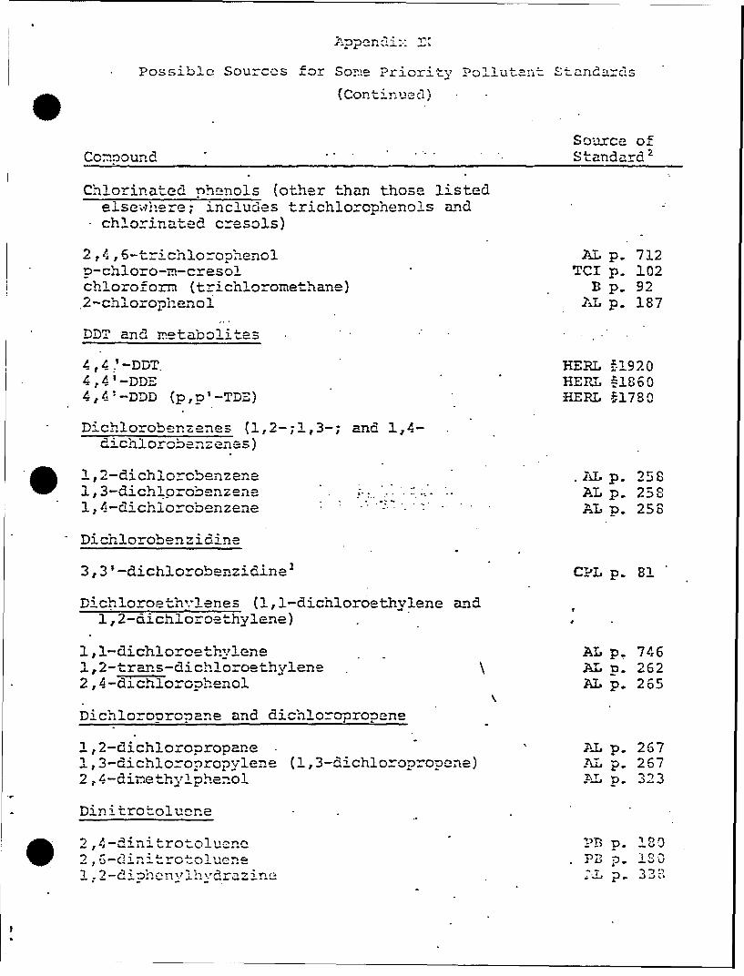
'*-?ossiblC Sourccs for So c! Priority Po'allutant Stad'ar-ds(Cont'inuced)
Source of
Comound ..... Standard2 P
acenaphthylene AN p. 1anthracene AN p. 1181, 12-benzonezrylne AN p. 118fluorene AN p. 118phen anthrene AN p. 118
1,2:5 ,6-dibenzanthracene AN p. i!eindeno (1,2,3-C,D)pyrene AN p. 118pyrene AN p. 118
_2,3,7,8-tdtrachlorcdibenzo-p-dioxin- (TCDD) NI p. 174tetrach0oroeth'ylene AL p. 680toluene AL p. 701toxanhene "IIEL -It- 67 -1.•0trichloroeth.lene AL p. 711vinyl chloride (chloroethylene) --. PB p. 406l-bromodecane (possible internal standard)1-bromododecane (possible internal standard)
Footnotes:
2 These compounds or any mixture containing 1% or more by X.7eight.of .these conpouds are defired as carcinogens in the FcderalRegister, Vol. 38, No. 144, pp. 20074-20076, 27 July 1973..Prescribed safety regulations for handling are in the FederalRegister, Vol. 39, No. 20, pp. 3756-3797, 29 January 1974.
2 Only one source is listed even though several may be available.These sources are not to be interpreted as being endorsed bythe EPA; they serve to show at least one ven'.or where eachstandard can be obtained. Whhen several sources were availableand coinpound purity was listed, the source having the highestpurity material w..,as selected.
* These ccTmpou-nds have been ordered but have not been recc'vedat At-hcns EIRL as vyt.
- No source has been found as yet.
courccz ofS-nar'
SA ., ..... A1Qric~h Chr:-=I_ Co icTh""Iq !7
AT,"Conn. e Ca Cat ag 1 97u7- 1 76)
* 4;AN Prialabs, Inc., 1o"rth Haven, Co.-In Catahg 18 (3une 1076
B J. T. Baker Chemical Co., Phillipsburgh, N.J.;Catalog 750 (July 1975).
CS Chen-Service, West Chester, Pa.; -Bulletin CS-!00-8 (1975).
CP" Cheinical Procurement Laboratories, College Point, N.Y.;1975 catalog.
EA Eastma._ Kodak Co., Rochester, N.Y.; Catalog 48 (1976).
ICN K&- Rare,& Fine Chemicals, Plainview, N.Y.; Catalog No. 10(1975).
I Nanogens International, P.O. Box 487, Freedom, CA 95019"Nainogen inde:" (1975).
PB Pfaltz & Bauer Chemical Co., STamnford, Conn. ; Catalog1976.
.-I*P.FR -'-:,*PR Corp., Hope, R.I. ; "Chemical Standards for Air-Water-.. Industry-Foods" (1975)..-
1E R L "AralYtical Reference Standards and Supplemental Data forPesticides and Other Selected Organic Compounds", EPA-
- 660/9-76-012 (May 1976), Health Effects Research LaboratoriEnviro.nental To-xicology Division, Research Triangle Park,
-C. A sa..me order blank for standards and the abovepublication are attached.
CO Columbia Organics Catalog A-7, Columbia, S.C. (1975).
TCI Tridom Chemical Inc., flau'tauge, N.Y. Catalog No. 1(1976).
-rJTD STATES ENVRONM, TLP TCT NG;Re~search Tri-innsic Piark.,-Ivorth Carolina 71
SUBJECT:IfiC.CfPZZ-5 C" 'nz,1T Wsta.ýA~r~a Update of 1Bailing List
ifM heal-th Effects Research Laboratorty, ETD, ACB,
ResearchM Triangla Park, 'NC, U.S..a. 27711 (1-45-69
TO: 711 L..*orat-ozy Fclte on, our M~ailing List
This cý_opy of tC'M 1976 re~s.nof our pesticides reference stan:!arsindlex w'.as laailea ta the address a~ppearing on our mailing list. As t~his
list is several years old, we are -sure t~hat a number of addresses havechanged and that, sozme are probably no longer existent.
If you wish to remaiin on our Mailing listC to receive future tmda-tesof this pub!1ication, w-ould you be sood enough. to cc-,n2.ete the alb)baeow, snip it off, and return it to us. .-Do not tCear of;-f the bac% cover.
- .to rat zn t4: t-he address sho-,;.. -if you have no use for this publicat-ionku 3now of-ý so=-: ot'her individual -within your organization w,.ho is con-
cerned~ with ueasticides analysis, would you convey this index, along wit* the lbaiaCk, to thna4 rerSon.______-
-- - -- - ----------- ------------------- ---- - ---
To:. U. S. nvir'on--ental Protection Agency__________}iealt~h -Effects Research Lalboratory DateBnvironmental ToxiCology DivisionResearch Triangle Park; It-, U.S.A. 27711 (I-M-69)
W~e wiht6ertando your railixig list to receive future uae
* - [flof the Pesticides Standards index. The ad;dress shown on the envelopeis entirely correct, and requires no changes.
D We have no interest in 1future up.,ates of thi's Publication. Please*cancel us Jfro-m your mailing list'.
rn a wi-sh to be retained on Your n~ailing list, but the addreSS showmL1 :n he cncoesoudb ca d to read (print or type)
Quality L-rarnze Soto /hr:.::tDZnv0roztal) Tic_1cgj~y Div-zz~ 'nn O" ;~
PA, IRL~~'L, FTzarh¶rizi:IIt2l -PtI, 2771a Or d Fi) 2-.DD-6 N X OT 1:izITZ J N T: 'Z
T7ie follvwing refer-ence st-anaards are re;uired for- oUr progra-:
Catalog Comnound Catal1og Co-mPou.-M
Codle (Catalog I17aME Cod!e (Catalog 1'ame)
VIO
fam an dIirs flaoao
afnedsay ex se-- ofc~ o-f sheet toly:*ý coral e list. oeringlete uneesar
Dfohi no i-s cpeste ino f lise s h-ctlglr
f.Th a 1,out -_I n c -c st C) ar.- is- net~cc to y0 ,~ r:ý=vs ca tn, ...I. n
~2. ~lcase eturr~ at o ~ -'~k-cr ent cad c-o- *i~- -
This~~~~~~~~~~~~~ -1vcc h oeei~: ~ ~ievo h -~-:-
2.D o cz 'es Lon r-Slse2T zfzctlg : '~e~n hot rte:;±ar to Zou m ý-t, .'-eCa_~~ ~r~ ~