3/20/2007N2:14:27 PM K O:\eoard\database\dbdocs\FY03\CRDF\039005\ZDD250.fpk REPORT DOCUMENTATION PAGE Form Approved OMB No. 0704-0188 Public reporting burden for this collection of information is estimated to average 1 hour per response, including the time for reviewing instructions, searching existing data sources, gathering and maintaining the data needed, and completing and reviewing the collection of information. Send comments regarding this burden estimate or any other aspect of this collection of information, including suggestions for reducing the burden, to Department of Defense, Washington Headquarters Services, Directorate for Information Operations and Reports (0704-0188), 1215 Jefferson Davis Highway, Suite 1204, Arlington, VA 22202-4302. Respondents should be aware that notwithstanding any other provision of law, no person shall be subject to any penalty for failing to comply with a collection of information if it does not display a currently valid OMB control number. PLEASE DO NOT RETURN YOUR FORM TO THE ABOVE ADDRESS. 1. REPORT DATE (DD-MM-YYYY) 13-03-2007 2. REPORT TYPE Final Report 3. DATES COVERED (From – To) 1 July 2004 - 13-Mar-07 5a. CONTRACT NUMBER FA8655-03-D-0001, Delivery Order 0012 5b. GRANT NUMBER 4. TITLE AND SUBTITLE Investigation Of Magnetohydrodynamic (MHD) Controlled Inlet With Nonequilibrium MHD Generator 5c. PROGRAM ELEMENT NUMBER 5d. PROJECT NUMBER 5d. TASK NUMBER 6. AUTHOR(S) Dr. Alexander L Kuranov 5e. WORK UNIT NUMBER 7. PERFORMING ORGANIZATION NAME(S) AND ADDRESS(ES) Leninetz Holding Company, NIPGS 212, Moskovsky Prospekt St. Petersburg 196066 Russia 8. PERFORMING ORGANIZATION REPORT NUMBER N/A 10. SPONSOR/MONITOR’S ACRONYM(S) 9. SPONSORING/MONITORING AGENCY NAME(S) AND ADDRESS(ES) EOARD PSC 821 BOX 14 FPO AE 09421-0014 11. SPONSOR/MONITOR’S REPORT NUMBER(S) EOARD Task 03-9005 12. DISTRIBUTION/AVAILABILITY STATEMENT Approved for public release; distribution is unlimited. 13. SUPPLEMENTARY NOTES 14. ABSTRACT This report results from a contract tasking Leninetz Holding Company, NIPGS as follows: The contractor will analytically investigate applying magneto hydrodynamic (MHD) generators to a generic hypersonic inlet. The inlet geometry will be a two-shock inlet with the total turning angle of 15° and designed for Mach 10. The contractor will evaluate the location and configuration of electromagnet coils and electrodes for the MHD system. Flow fields in the MHD controlled inlet will be calculated in 2D Euler approach. Analysis of elementary processes responsible for flow ionization will be assessed. Space distribution for power density deposited in the flow and for conductivity of flow due to e- beam propagation will be calculated. A mathematical model of the MHD-controlled inlet with non-equilibrium MHD generators using e-beams as the ionizer will be developed. Finally, flow fields in the MHD-controlled inlet will be calculated in a wide range of parameters (altitude, Mach number, contraction ratio, MHD and ionizer parameters. The main characteristics of the inlet will be determined, such as the air mass flow- rate, flow compression, and total pressure recovery. Requirements for the magnetic system and ionizer, which ensure efficient control of inlet at off-design conditions, will be formulated. 15. SUBJECT TERMS EOARD, Magnetohydrodynamic (MHD), Inlets, Hypersonic Flow 16. SECURITY CLASSIFICATION OF: 19a. NAME OF RESPONSIBLE PERSON SURYA SURAMPUDI a. REPORT UNCLAS b. ABSTRACT UNCLAS c. THIS PAGE UNCLAS 17. LIMITATION OF ABSTRACT UL 18, NUMBER OF PAGES 73 19b. TELEPHONE NUMBER (Include area code) +44 (0)20 7514 4299 Standard Form 298 (Rev. 8/98) Prescribed by ANSI Std. Z39-18
Transcript
3/20/2007N2:14:27 PM K O:\eoard\database\dbdocs\FY03\CRDF\039005\ZDD250.fpk
REPORT DOCUMENTATION PAGE Form Approved OMB No. 0704-0188
Public reporting burden for this collection of information is estimated to average 1 hour per response, including the time for reviewing instructions, searching existing data sources, gathering and maintaining the data needed, and completing and reviewing the collection of information. Send comments regarding this burden estimate or any other aspect of this collection of information, including suggestions for reducing the burden, to Department of Defense, Washington Headquarters Services, Directorate for Information Operations and Reports (0704-0188), 1215 Jefferson Davis Highway, Suite 1204, Arlington, VA 22202-4302. Respondents should be aware that notwithstanding any other provision of law, no person shall be subject to any penalty for failing to comply with a collection of information if it does not display a currently valid OMB control number. PLEASE DO NOT RETURN YOUR FORM TO THE ABOVE ADDRESS. 1. REPORT DATE (DD-MM-YYYY)
13-03-2007 2. REPORT TYPE
Final Report 3. DATES COVERED (From – To)
1 July 2004 - 13-Mar-07
5a. CONTRACT NUMBER FA8655-03-D-0001, Delivery Order 0012
5b. GRANT NUMBER
4. TITLE AND SUBTITLE
Investigation Of Magnetohydrodynamic (MHD) Controlled Inlet With Nonequilibrium MHD Generator
5c. PROGRAM ELEMENT NUMBER
5d. PROJECT NUMBER
5d. TASK NUMBER
6. AUTHOR(S)
Dr. Alexander L Kuranov
5e. WORK UNIT NUMBER
7. PERFORMING ORGANIZATION NAME(S) AND ADDRESS(ES) Leninetz Holding Company, NIPGS 212, Moskovsky Prospekt St. Petersburg 196066 Russia
8. PERFORMING ORGANIZATION REPORT NUMBER
N/A
10. SPONSOR/MONITOR’S ACRONYM(S)
9. SPONSORING/MONITORING AGENCY NAME(S) AND ADDRESS(ES)
EOARD PSC 821 BOX 14 FPO AE 09421-0014
11. SPONSOR/MONITOR’S REPORT NUMBER(S)
EOARD Task 03-9005
12. DISTRIBUTION/AVAILABILITY STATEMENT Approved for public release; distribution is unlimited. 13. SUPPLEMENTARY NOTES
14. ABSTRACT
This report results from a contract tasking Leninetz Holding Company, NIPGS as follows: The contractor will analytically investigate applying magneto hydrodynamic (MHD) generators to a generic hypersonic inlet. The inlet geometry will be a two-shock inlet with the total turning angle of 15° and designed for Mach 10. The contractor will evaluate the location and configuration of electromagnet coils and electrodes for the MHD system. Flow fields in the MHD controlled inlet will be calculated in 2D Euler approach. Analysis of elementary processes responsible for flow ionization will be assessed. Space distribution for power density deposited in the flow and for conductivity of flow due to e-beam propagation will be calculated. A mathematical model of the MHD-controlled inlet with non-equilibrium MHD generators using e-beams as the ionizer will be developed. Finally, flow fields in the MHD-controlled inlet will be calculated in a wide range of parameters (altitude, Mach number, contraction ratio, MHD and ionizer parameters. The main characteristics of the inlet will be determined, such as the air mass flow-rate, flow compression, and total pressure recovery. Requirements for the magnetic system and ionizer, which ensure efficient control of inlet at off-design conditions, will be formulated.
16. SECURITY CLASSIFICATION OF: 19a. NAME OF RESPONSIBLE PERSON SURYA SURAMPUDI a. REPORT
UNCLAS b. ABSTRACT
UNCLAS c. THIS PAGE
UNCLAS
17. LIMITATION OF ABSTRACT
UL
18, NUMBER OF PAGES
73 19b. TELEPHONE NUMBER (Include area code)
+44 (0)20 7514 4299
Standard Form 298 (Rev. 8/98) Prescribed by ANSI Std. Z39-18
FINAL REPORT
ON CRDF DELIVERY ORDER0012, EOARD 034005, CRDF RPO-1396-ST-03,
ENTITLED “INVESTIGATION OF MHD-CONTROLLED INLET WITH NONEQUILIBRIUM MHD GENERATOR”
(From July 1, 2004 to December 30, 2006)
Alexander Leonidovich Kuranov
(Project Manager)
“Hypersonic Systems Research Institute” Joint Stock Company
December 2006
This work was supported financially by the USAF under the contract with the Civilian Research and Development Foundation
CONTENTS 1. Analysis of potential schemes of nonequilibrium MHD generator in scramjet inlet and consideration of theirs realizability will be done. Possible configurations of magnetic field, location and configuration of electrodes will be discussed. More preferable configuration will be chosen.................................................................... 2 2. Kinetic scheme for description of nonequilibrium plasma creation in channel of mhd generator by e-beam ionizer will be developed. Influence of induced electric field in mhd channel on electron concentration sustained by e-beam ionizer will be investigated. electron concentration will be calculated for steady and pulse periodic e-beams both for one beam and for set of spaced beams. power cost to creation of any given electron concentration in typical for mhd-controlled inlet conditions will be estimated............................................................................................................. 12 3. Mathematical model to describe the electron beam propagation in homogeneous supersonic flow in presence of magnetic field will be developed on a base of Boltzmann kinetic equation in approach of continuous deceleration. Self-consistent approximation with taken into account the space charge and kinetics of plasma creation is considered. ............................................................................................. 22 4. Mathematical model to describe the electron beam propagation in nonuniform supersonic flow in presence of magnetic and electric fields will be developed on a base of Boltzmann kinetic equation in approach of continuous deceleration. Self-consistent approximation with taken into account the space charge and kinetics of plasma creation is considered. Space distribution of electron and ion concentrations will be calculated in typical for MHD-controlled inlet conditions ......................... 32 5. Monte Carlo code to calculation of e-beam propagation in nonuniform supersonic flow in presence of magnetic and electric fields will be developed. .... 43 6. Comparative analysis of space distributions of power density spent on flow ionization by e-beam calculated both in Monte Carlo code and in Boltzmann kinetic equation solution. Improvement of mathematical model of e-beam propagation in nonuniform supersonic flow will be done. Rapid method to calculate space distribution of electric conductivity at given parameters of e-beam and structure of gas-dynamic flow in inlet will be developed. ............................... 49 7. Mathematical model of MHD-controlled inlet with nonequilibrium MHD generator using e-beam, as ionizer, will be developed in 2D Euler approach. Iterative scheme will be used, which takes into account that both flow structure influence on conductivity distribution and nonequilibrium MHD generator modify flow structure........................................................................................................... 60 8. Characteristics of MHD-controlled inlet in a wide range of parameters variation (altitude, Mach number, inlet geometry, MHD and ionizer parameters) will be calculated. Requirements for magnetic system and ionizer, which ensure efficient control of inlet at off-design conditions, will be formulated .................................. 66 Conclusion............................................................................................................... 71
1
1. Analysis of potential schemes of nonequilibrium MHD generator in scramjet inlet and consideration of theirs realizability will be done. Possible configurations of magnetic field, location and configuration of electrodes will be discussed. More preferable configuration will be chosen
The first stage of the project is devoted to analysis of potential schemes of the nonequilibrium MHD generator in the scramjet inlet, possible configurations of a magnetic field, location and configuration of electrodes. The main objective for the nonequilibrium MHD generator in the scramjet inlet is improvement of the inlet characteristics at off-design conditions. It is well known, that at flight Mach numbers M∞ exceeding design Mach number Md, the MHD generator can be used for modification of the flow field in the inlet and making it quite similar to the one at design conditions. At flight Mach numbers below the design Mach number the MHD generator allows one to increase the air capture in the inlet.
In order to ensure significant MHD influence on a flow in the inlet, it is necessary to create a magnetic field and provide high enough level of an electric conductivity of the flow. The static temperature of the flow in the inlet is insufficient to provide equilibrium conductivity, thus it is necessary to ionize the flow using methods for producing nonequilibrium conductivity. In our project the electron beam is considered as ionizer. As a base for the inlet geometry, the two-shock inlet with the total turning angle of 15° and the Mach design number Md=10 is chosen. The scheme of the inlet is shown in Fig.1. The total turning angle in the inlet is θN=θ1+θ2=15°, where θ1=6.5° and θ2=8.5°, the height of the throat is Fth=0.12m. Flow field in the MHD controlled inlet will be calculated in 2D Euler approach for selected configurations of magnetic field and ionized region. Computational procedure is based on the explicit high-resolution shock-capturing Godunov-type scheme.
A source of magnetic field in the project is electromagnet. The top values of a magnetic flux density can be obtained if we use the superconducting electromagnet. It seems more realistic to locate the electromagnet inside the body of the scramjet inlet, because placement of any part of the magnet in a flow outside the body can increase the drag of the flight vehicle. Feasible location points of electromagnets in the scramjet inlet were analyzed at the first stage of the project. A version of the electromagnet coil location enabling realization of the MHD influence on the flow in the inlet is presented in Fig.2. In this case, the magnetic field is produced by a single coil which has a profile adapting both to design of the flight vehicle and requirements to the MHD generator which controls the flow in the inlet. In the figure the coil is not closed. Its prolongation can engage the isolator which is positioned upstream of the combustion chamber, the combustion chamber itself and the part of the scramjet downstream of it. The magnetic field in the above subsystems of the scramjet can, in principle, be used to control the internal flow in the scramjet in order to improve its performance. The scheme of the scramjet with MHD bypass can be used for the purpose. The coil in the plane of its cross-section basically can have just any profile. In this project we restrict our analysis to only two profiles consideration, namely rectangular and circular ones. Feasible location points of electrodes are shown schematically in Fig.2. The electrodes denoted in the figure by number 1 and number 2 can be used in the MHD controlled inlet both jointly and separately.
To calculate the magnetic field in the region of MHD interaction we use the non-inductive approach, typical for MHD generator conditions. This approach corresponds to magnetic Reynolds number Rem<<1. In this case, a magnetic field induced by current in the plasma is negligible by comparison with the magnetic field created by the current in the electromagnet coil. The magnetic field distribution is calculated by means of Maxwell's equations. The steady state equations are considered for which: rot , div 0cμ=B j B = , where B is the magnetic induction vector, jc is the current density in the electromagnet coil, μ is the magnetic permeability of a medium. In calculations we use μ=μ0=4π⋅10−7 N/A2. To determine the magnetic field we introduce the vector potential A, which is connected with the magnetic
2
field by the ratio rot=B A
z
. Equations for Cartesian components of the vector potential have a form of Poisson's equation:
, , ,i ciA j i x yμΔ = = (1) If we know the current density in the electromagnet coil, for example, function jcz(x,y), then solution of equations (1), correspondingly for Az, can be obtained in the form [1]:
( )( ) ( )2 2
1 1, ( , ) ln2z c zA x y j d d
x yμ ξ η ξ η
π ξ η
∞ ∞
−∞ −∞
=− + −
∫ ∫ (2)
Equations for other components of the vector potential have the same form. The magnetic flux density can be determined from the vector potential by using the well
known equations: yz
x
x zy
y xz
AABy zA ABz x
A ABx y
∂∂= −∂ ∂∂ ∂
= −∂ ∂∂ ∂
= −∂ ∂
(3)
It is shown in Ref. [2] that a positive effect of MHD control in the MHD controlled inlet at flight Mach numbers greater than the design Mach number (M∞>Md) is achievable in a wide range of variation of such characteristics as the magnetic field orientation and a configuration of the region of MHD interaction. On the other hand, in the case of M∞<Md the effect of MHD control depends significantly on the magnetic field orientation. That is why we try to satisfy the requirements for the MHD control in the inlet at off-design conditions with M∞<Md in choosing the magnetic field configuration. The more significant positive effect of MHD control in the inlet at M∞<Md consists in increasing the air capture. In order to effectively increase the air capture in the MHD controlled inlet, it is necessary to organize the MHD influence on the flow in such a way that the Lorentz force projection directed to the inlet body receives a maximal value [3]. The Lorentz force is defined by the ratio = ×f j B . The current density in the region of MHD interaction is determined by the Generalized Ohm's law ( ) (eμ σ )+ × = + ×j j B E v B , where eμ is the electron mobility, E is the electric field intensity.
The scramjet inlet lock-on in the Cartesian coordinates corresponds to one shown in Figs.1,2. Two-dimensional approach in which the flow parameters along the 0Z axis are invariable is considered. The nonequilibrium MHD generator configuration must provide high value of the Lorentz force directed to the inlet body. So it makes some requirements to configuration of the magnetic field and the location of the region of MHD interaction. Besides, the absolute value of the Lorentz force projected on the Z axis zf needs to be minimized. It follows from the analysis made that the Faraday MHD generator with sectioned electrodes meets the requirements substantially. In case of ideally sectioned Faraday MHD generator fz=0. As for space position of electrodes, the magnetic field nonuniformity allows one to locate the electrodes both on the surface of the flight vehicle and in the plane located at some angle to it. Schematically location of the electromagnet coil and MHD electrodes and also configuration of the magnetic field and the MHD current are shown in Figs.3,4. Fig.3 corresponds to the region with electrodes which is marked by number 2 in Fig.2b. Fig.4 corresponds to the region with electrodes which is marked by number 1 in Fig.2b.
A part of the MHD controlled inlet with two types of conductor producing a magnetic field is shown schematically in Fig.5. Here the conductors with circular and rectangular cross-sections which carry the current Ic along the axis 0Z are shown. Parameters which determine the value and the space distribution of the magnetic field are shown in Figs.5a,b. Here we are listing the following parameters: position (x0,y0) of a conductor center, magnitude of the current Ic,
3
width h and height d for the rectangular conductor and also angle θc for orientation of the conductor plane relatively to the x axis. In case of a conductor with a circular cross section a magnetic field outside the conductor depends upon the distance from the point (x0,y0) and the value of Ic and doesn’t depend on the radius of the conductor. It is shown in calculations, that in case of a rectangular conductor with realistic proportions in the MHD controlled inlet (d<<h) the magnetic field distribution practically doesn’t depend upon the d value. The magnetic field distributions in the MHD controlled inlet for conductors with rectangular and circular cross-sections are compared in Fig.6. It is easy to see that near the inlet surface the magnetic fields for the cases significantly differ. When moving away from the surface, the difference between the magnetic fields is less.
We consider the electron beam as an ionizer which produces the nonequilibrium conductivity of the flow in the scramjet inlet. Estimations show that in typical conditions of the
MHD controlled inlet a magnitude of the Larmor radius LmvreB
= for electrons of the e-beam is
significantly less than the path length of the electrons between elastic collisions, here m is the electron mass, v is a velocity of the electron, e is the electron charge. Therefore, the electrons in the e-beam propagate in the flow practically along the magnetic field line. Depth of propagation of electrons in the flow depends upon the flow density and the initial energy of the electrons. So, a location and proportions of the region of the nonequilibrium conductivity depend on the magnetic field configuration, the space location of the e-beam emitted into the flow, the e-beam characteristics and the flow characteristics. Possible space location of e-beam in the MHD controlled inlet is shown in Fig.7. This situation corresponds to the magnetic field produced by the conductor with a circular cross-section centered at the point (x0,y0). In this case the electrons in the e-beam move along the concentric circles. The geometrical locus of the region of the nonequilibrium ionization can be characterized by the center position (x0,y0), magnitudes of external Rext and internal Rint circles and the angle θ which determines the electrons ranges in the flow. In order to determine the region of the nonequilibrium ionization in general with an arbitrary configuration of the magnetic field, it is necessary to solve a differential equation for trajectories of electrons in the e-beam traversing the inlet surface in any given area. We consider configuration in which the magnetic field is produced by a current or a system of currents directed along the 0Z axis. One of the examples of such configuration is shown in Fig.4. As in this case the magnetic field has only two components BBx(x,y) and ByB (x,y), the differential equation for a trajectory of electrons from e-beam which are passing through a point (x1,y1) has the form:
y
x
Bdydx B
=
with the boundary condition y(x=x1)=y1. The curves passing through the points bounding the area of the e-beam emission from the inlet surface determine the bounds of the region of nonequilibrium ionization. Depth of the e-beam penetration is considered at this stage as a parameter which can be varied in calculations. Power density qi deposited by the e-beam in the region of ionization is supposed to be constant in the region. The ionization degree in the flow and its conductivity are calculated in using approximating functions from Ref. [4]. At the following stages of the project a method of calculation of the region of the nonequilibrium ionization will be developed which will provide for more adequate description of the real conditions in the MHD controlled inlet.
In order to define what profile of a conductor producing a magnetic field in the MHD controlled inlet is preferable, computations of flow fields in the inlet with the configuration shown in Fig.4 were made. Flow regime with M∞<Md was considered. As a more significant characteristic, the air mass flow rate in the inlet was considered in analysis. The position of the magnetic field source (x0,y0) and also the values h and θc (for rectangular conductor ) were varied in the computations. Bounds of the e-beam emission in the flow were varied in the computations
4
too. As a result of computations it is shown that the MHD control allows one to increase the air capture in the inlet in using both circular and rectangular profiles for the conductor. Nevertheless, usage of the conductor with a circular cross-section presents a small advantage in the air capture. This is demonstrated in Fig.8, here ϕh is the air mass flow rate in the MHD controlled inlet with a current geometry corresponding to Fig.5b, ϕR is the air mass flow rate in the MHD controlled inlet with a current geometry corresponding to Fig.5a.
We have also investigated characteristics of the MHD controlled inlet in which a magnetic field is produced by two antiparallel currents as is shown in Fig.9. Computations show that at such configuration of a magnetic field the MHD control of a flow in the MHD controlled inlet is more effective than at configurations of a magnetic field considered previously. For example, in the configuration shown in Fig.7 at flight Mach number M∞=8 and Ic=107A a relative increase of the air capture due to MHD control doesn’t exceed 2.5%. At the same time, in the configuration shown in Fig.9 the relative increment grows up to 10%. Fig.10 demonstrates the flow field in the MHD controlled inlet calculated for configuration shown in Fig.9. One can see that a streamline entering the region of MHD interaction is deflected to the body. This effect is more obvious in the fragment of the flow field presented in Fig.10b. It is this kind of transformation of a flow that increases the air capture in the MHD controlled inlet.
Characteristics of the MHD controlled inlet computed at this stage will be presented in the annual report for the set of locations of the magnetic field sources, different values of the current Ic, at various characteristics of MHD generator and diverse locations of an area of the e-beam input into the flow.
Fig.1 Geometry of inlet used in calculations. Md=10, θ1=6.5°, θ2=8.5°, θN=15°, Fth=0.12m.
a) side view
5
b) bottom view Fig.2 Sketch for possible configuration of an electromagnet coil adapting to the construction of the scramjet inlet
a)
6
b) Fig.3 Sketch for configuration of a magnetic field and MHD currents corresponding to location of electrodes marked by number 2 in Fig.2b.
Fig.4( Sketch for) configuration of a magnetic field and MHD currents corresponding to location of electrodes marked by number 1 in Fig.2b
7
a) b) Fig.5 Part of the MHD controlled inlet with a current which produces a magnetic field
Fig.6 Contours of the magnetic flux density for two various currents. Black lines correspond to the circular conductor, red lines correspond to the rectangular current with h=0.5m, θc=8°; Ic=5⋅106A, x0=0.4m, y0=4.1m.
8
Fig.7 Sketch for MHD controlled inlet with circular magnetic field.
0,2 0,4 0,6 0,8 1,00,994
0,995
0,996
0,997
0,998
0,999
1,000
ϕ h/ϕR
h, m Fig.8 Relative air mass flow rate in the MHD controlled inlet. M∞=6, Md=10, θc=9°, x0=4.0m, y0=0.4m, Ic=107A
9
0 1 2 3 4 5 6 70,0
0,2
0,4
0,6
0,8
1,0
1,2
(xb, yb)Y, m
X , m
.+
(xa, ya)
Fig.9 MHD controlled inlet with two antiparallel currents which are used to produce magnetic field.
a)
10
b) Fig.10 Density contours in the MHD controlled inlet (a) and its fragment (b) at M∞=8, Md=10, xa=4.0m, ya=0.4m; xb=5.35m, yb=0.8m, Ic=107A
11
2. Kinetic scheme for description of nonequilibrium plasma creation in channel of mhd generator by e-beam ionizer will be developed. Influence of induced electric field in mhd channel on electron concentration sustained by e-beam ionizer will be investigated. electron concentration will be calculated for steady and pulse periodic e-beams both for one beam and for set of spaced beams. power cost to creation of any given electron concentration in typical for mhd-controlled inlet conditions will be estimated
The second stage of the project is devoted to development of kinetic scheme for
description of nonequilibrium plasma creation in channel of MHD generator by e-beam ionizer. Concentrations of charged particles: electrons, positive and negative ions are calculated for steady and for pulse periodic e-beams both for homogeneous ionizer and for set of spaced beams. Dependencies of electron concentration are presented in function of power density spent on ionization in typical for MHD-controlled inlet conditions. It allows one to estimate power costs for creation of any given electron concentration in the MHD-controlled inlet. Influence of induced electric field in MHD channel on electron concentration sustained by e-beam ionizer is investigated too. The simple approach for calculation of electron temperature in conditions of MHD controlled inlet is proposed.
The two-shock inlet with the total turning angle θN=θ1+θ2=15°, where θ1=6.5° and θ2=8.5° was considered in calculations. In the MHD controlled inlet there are three different regions of a flow in which efficiency of the e-beam ionizer will be different too. They are denoted in Fig.1 by next symbols: FS is the free stream, S1 is the flow after the first oblique shock and S2 is the flow after the second oblique shock. Flow parameters in these regions are calculated numerically in using 2D Euler approach. Gas concentration N in the free stream flow (the region FS) depending on the flight Mach number M∞ is presented in Fig.2 for two values of the free-stream dynamic pressure q∞.
In this stage we consider approach in which plasma concentration is changed only along the direction of the flow velocity (x in our designations). Transversal modification of plasma concentration due to the e-beam energy degradation will be considered in the following stages. To calculate non-equilibrium conductivity of a flow in channel of MHD generator with e-beam ionizer we consider model of a low ionized plasma consisting of neutral molecules, electrons, negative and positive ions with corresponding number densities: , n
2 2, O NN e, n-, n+. In report [1] it is shown that results obtained in such type of model are in good accordance with ones obtained in the model taking into account more than 40 plasma components and more than 230 reactions of the plasma components. Moreover, according to Ref. [2] predictions of the model are adjusted with experiment. Set of kinetic equations for concentrations of the plasma components is the next:
2 2
2 2
2
2
( , )
( , )
e ed O a O e ei
ii ei e
a O e d O ii
n nv I t x k N n k N n nt xn nv I t x n n n nt x
n nv k N n k N n n nt x
β
β β
β
− +
+ ++ − +
− −− + −
∂ ∂+ = + ⋅ ⋅ − −
∂ ∂∂ ∂
+ = − −∂ ∂∂ ∂
+ = − ⋅ −∂ ∂
en
, (1)
12
where v is the flow velocity, ( , )I t x is e-beam induced ionization rate, is concentration of oxygen molecules in air, k
2ONa and kd are the rate constants of attachment and detachment of
electrons respectively, β and βii are the rate constants for electron-ion and ion-ion recombination respectively. These constants are functions of gas temperature T and electron temperature Te. In calculations we use dependencies from papers [3, 4]. In kinetic scheme (1) the processes of attachment and detachment of electrons to nitrogen molecules are not accounted because in considered conditions their rate constants can be neglected in comparing with ones for corresponding processes with oxygen molecules participated in. Ionization rate I is determined in terms of e-beam characteristics by the relation:
( ) ( )( , ) ( , ) ( , )b bion
i i
j e Y EqI t x f t x f t xW W
ρ= ⋅ ≡ ⋅ (2)
where jb is the e-beam current density, Eb is the energy of electron, Y is the electron stopping power, ρ is the gas density, Wi is the ionization cost. Dimensionless function ( , )f t x determines spatial and temporal distribution of the power deposition into the flow. Value qion in Eq.(2) determines power lost by electron beam in the flow in unit of time in unit of volume. The value qion is used in calculations as a parameter which characterizes the ionizer. In the first phase of this stage of investigations we consider approach Te=T which is correct in absence of magnetic field.
Concentrations of charged particles were calculated for different values of qion, different flow parameters and different functions ( , )f t x . Firstly the steady state approach was investigated for which , , 0en t+ −∂ ∂ = and correspondingly ( )( , )f t x f x= . Fig.3 shows electron
concentration calculated in considering the e-beam occupying the half-space: ( )0, 01, 0
xf x
x<⎧
= ⎨ ≥⎩.
One can see that in this case electron concentration increases while increasing the x value and tends to a limiting magnitude. These limiting magnitudes of electron concentration are shown in Fig.4 in function of the power density spent on the flow ionization for various values of the flight Mach number. In order to investigate specificity of a nonuniform ionization of the flow we have made calculations of concentrations of charged particles in plasma sustained by periodically spaced e-beams. Fig.5 shows one of periodical functions ( )f x used in calculations. Space distribution of electron concentration produced by such set of e-beams is shown in Fig.6. Fig.7 shows another type of periodical function ( )f x which was used in calculations. Fig.8 demonstrates space distribution of electron concentration produced by this set of e-beams. One can see that space distributions of electron concentration in Figs.6,8 are periodical too.
Secondly the nonsteady but uniform approach was investigated for which , , 0en x+ −∂ ∂ =
and correspondingly ( )( , )f t x f t= . Results of calculations presented in Fig.9, corresponds to
. Fig.10 demonstrate time-dependent electron concentration in uniform plasma
sustained by pulse-periodic e-beam with a period T=2⋅10
( )0, 01, 0
tf t
t<⎧
= ⎨ ≥⎩-5s. And then the more complicated
situation in which concentration of charged particles varying both in time and in space directions was considered. Fig.11 demonstrates time and space dependency of electron concentration in plasma sustained by periodically spaced set of pulse-periodic e-beams which is described by set of equations (1) with ( ) ( )( , )f t x f t f x= ⋅ . In analyzing the results of calculations the conclusion was made that in case of both space and time dependent plasma concentrations the averaged concentrations of charged particles can be determined by considering uniform and steady state plasma sustained by uniform and steady e-beam with averaged value of power spent on flow ionization.
13
Electron concentration in regions FS, S1 and S2 of MHD controlled inlet was calculated at various values of qion for flight Mach numbers varying from 6 to 12 and various values of free stream dynamic pressure. Results of calculation were approximated by simple functions distinct for different regions of a flow. Numerical results and approximation function for FS region are presented in Fig.12.
Next phase of this stage of research was devoted to investigation of influence of induced electric field in MHD channel on electron temperature and electron concentration sustained by e-beam ionizer. Results obtained in Refs [5, 6] were used to formulate the simple approach for calculation of electron temperature in conditions of MHD controlled inlet. It is taken into account in this approach that electron temperature depends on the ratio of the “so-called”
effective electric field 21
effEEβ
′=
+ to the gas concentration N, where is the electric field in
the MHD generator in the reference system moving together with a flow, β is the Hall parameter. Scheme of ideally sectioned Faraday MHD generator was considered. It is shown that electron temperature depends on the magnetic flux density, the flow velocity, the gas concentration and the load factor k. One of calculations of T
E′
e in FS region is shown in Fig.13. One can see that temperature of electrons depends significantly upon the magnetic flux density. Since the constant of reactions in kinetic scheme depends both on the gas temperature and electrons temperature, thus the ionization degree in the MHD generator will depend on the magnetic flux density. Fig.14 demonstrates the ionization degree in the MHD generator with nonequilibrium conductivity in function of magnetic flux density for two values of the power density spent on flow ionization. One can see that increasing the magnetic flux density causes the ionization degree to increase. So effect of increasing of electrons temperature in the MHD generator investigated is very important and need to be taken into account in calculations of a nonequilibrium plasma concentration.
Calculated concentrations of charged particle in plasma sustained by e-beam in FS, S1 and S2 regions of the MHD controlled inlet will be presented in the annual report for various values of qion, B, q∞, M∞. Simple formulas for calculations of important characteristics of the nonequilibrium plasma will be presented too.
14
Fig.1 Sketch for MHD controlled inlet.
6 7 8 9 10 11 120
1
2
3
4
5
6
7
8
9
10
N⋅1
0-17 , c
m-3
M∞
q∞, kPa
75
40
Fig.2 Flow density in FS region depending on the flight Mach number.
15
0 1 2 3 4 50,0
0,2
0,4
0,6
0,8
1,0
M∞
6 8 10
n e⋅10
-12 , c
m-3
x, cm
Fig.3. Spatial dependencies of electron concentration in FS region at qion=1W/cm3, q∞=75 kPa.
0,1 1 100,1
1
n e⋅10
-12 , c
m-3
qion, W/cm3
M∞
6 8 10
Fig.4. Dependencies of electron concentration in FS region upon the power density spent on the flow ionization at q∞=75 kPa.
16
0 4 8 12 16 200,0
0,2
0,4
0,6
0,8
1,0
δx
f(x)
x, cm
Δx
Fig.5. Function ( )f x for periodically spaced e-beams in form of a slab with Δx=4cm, δx=4cm.
0 4 8 12 16 200,0
0,2
0,4
0,6
0,8
1,0
n e⋅10-1
2 , cm
-3
x, cm
M∞
6 8 10
Fig.6. Electron concentration in FS region for periodically spaced e-beams with ( )f x shown in fig.5 at qion=1W/cm3, q∞=75 kPa, Δx=4cm, δx=4cm.
17
0 4 8 12 160,0
0,2
0,4
0,6
0,8
1,0
f(x)
x, cm
Dx
Fig.7. Function ( )f x for periodically spaced e-beams in form of a peak with Dx=4cm.
0 4 8 12 160,0
0,1
0,2
0,3
0,4
0,5
0,6
0,7
n e⋅10
-12 , c
m-3
x,cm
M∞
6 8 10
Fig.8. Electron concentration in FS region for periodically spaced e-beams with ( )f x shown in fig.7 at qion=1W/cm3, q∞=75 kPa, Dx=4cm.
18
0,0 5,0x10⁻⁶ 1,0x10⁻⁵ 1,5x10⁻⁵ 2,0x10-50,0
0,2
0,4
0,6
0,8
1,0
n e⋅10-1
2 , cm
-3
t, s
M∞
6 8 10
Fig. 9 Time-dependent electron concentration in uniform plasma sustained by e-beam in FS region at qion=1W/cm3, q∞=75 kPa.
Fig.10 Time-dependent electron concentration in uniform plasma sustained by pulse-periodic e-beam with T=2⋅10-5s in FS region at qion=1W/cm3, q∞=75 kPa.
19
Fig.11 Time and space dependent electron concentration (in cm-3) in plasma sustained by periodically spaced set of pulse-periodic e-beams with T=1⋅10-5s and Dx=4cm in FS region at M∞=7, qion=1W/cm3, q∞=75 kPa
1E-3 0,01 0,1 1 100,1
1
10
q∞, kPa
75 40 6 8 10 12
M∞
(ne/N
)⋅106
(qion / N2)⋅1034, W⋅cm3
0.125⋅[(1+5160x)0.501-1]
Fig.12 Ionization degree depending on the parameter qion/N2 for FS region.
20
0,1 1 100,01
0,1
1
Te, e
V
B, T Fig.13. Electron temperature in FS region in function of the magnetic flux density B, in MHD generator with a load factor k=0.5 at M∞=6, q∞=75 kPa.
0,1 1 10
1
10
qion, W/cm3
10.0
1.0
n e/ N ⋅
106
B, T
Fig.14. Ionization degree for two values of qion in the nonequilibrium MHD generator located in FS region at M∞=6, q∞=75 kPa.
21
3. Mathematical model to describe the electron beam propagation in homogeneous supersonic flow in presence of magnetic field will be developed on a base of Boltzmann kinetic equation in approach of continuous deceleration. Self-consistent approximation with taken into account the space charge and kinetics of plasma creation is considered.
One of the most important characteristics for MHD controlled inlet is the flow conductivity produced by e-beam. Local concentration of electrons and of course local conductivity of the flow depends on the local value of the power density spent on ionization. High-speed electrons moving in gas loses energy in elastic and inelastic collisions with molecules of air it leads to modification of electrons energy distribution function. Thus the power deposited by e-beam in the flow will be a function of distance passed by electrons. So to calculate the space distribution of the power deposited by e-beam in the MHD controlled inlet it is necessary to find the distribution function of electrons in e-beam. This problem is solved in the stage of the project. The second problem investigated in the work is connected to estimation of influence of electric field which is produced by uncompensated space charge of e-beam on the e-beam propagation.
The mathematical model for description of propagation of electron beam in homogeneous air flow in presence of magnetic field is developed on the basis of Boltzmann kinetic equation. In conditions typical for MHD controlled inlet the distribution function for electrons in e-beam (which is used for creation of nonequilibrium conductivity), can be described by the Boltzmann kinetic equation for fast particles moving in the gas of slow molecules [1]:
( ) ( )
( ) ( )2
, ( , , , )
, ,( , , , ) ( , , , )
f f ft N p vf p tt
d p pN d dp v p f p t Q p
dpd
σ
σ
∂ ∂ ∂+ + = − +
∂ ∂ ∂
′ ′→′ ′ ′ ′ ′+ +∫ ∫
v F r r Ωr p
Ω ΩΩ r Ω r Ω
Ωt
(1)
where ( , , , )f p tr Ω is the distribution function of fast particles, r is the radius-vector of the fast particle position, p is the fast particle momentum, Ω is the unit vector which determines moving direction of the fast particle ( p=Ω p ), t is the time, v is the fast particle velocity,
( )2 , ,d p pdpd
σ ′ ′→Ω ΩΩ
is the differential cross-section of scattering,
( ) ( ) ( )2 , ,d p p
d dpv p pdpd
σσ
′ ′→′ =∫ ∫
Ω ΩΩ
Ω′ is the total cross-section of scattering,
is the source function for fast particles,
( , , , )Q p tr Ω
( )t,F r is the force acting on the particle, N is concentration of molecules in gas.
Analysis has shown that in conditions of MHD controlled inlet the Larmor radius of electrons in e-beam significantly less than free path of electrons between elastic collisions. So, electrons in e-beam move practically along the magnetic field. We will consider steady state situation. The magnetic field is supposed to be uniform and perpendicular to the inlet surface. The electric field initially is supposed to be zero. It is evident that in this case the energy distribution function of electrons will depend only on the distance x from the surface which the e-beam is emerged from. In this case the kinetic equation for fast electrons can be rewritten in the form [2]:
( ) ( ) ( )( , , ) , , ( , , ) ( , , )N T x T N d dT T g T T x T Q x Tx
where ( , , ) ( , , )x T vf x Tμ μΦ = is the flux density of fast electrons, T is kinetic energy of electron, μ = 0ΩΩ , is the unit vector which determines initial direction of e-beam, 0Ω ( ), ,g T Tμ μ′ ′→ is the scattering indicatrix i.e. the probability density that electron parameters ,T μ′ ′ take values
,T μ in result of scattering. Relationship between μ and μ′ is determined by the formula: 2cos 1 sin cosμ μ θ μ θ′ ′= + − ψ , where θ is the scattering angle of electron in the laboratory
system ( cosθ ′=ΩΩ ), ψ– is the azimuthal scattering angle. In the general case ( )Tσ ′ is the total cross-section of electron scattering which includes both elastic and inelastic scattering. It is necessary to note that if we will consider a nonuniform magnetic field we can use the equation (2) for description of distribution function of electrons by substituting length of electrons track along the magnetic field line instead of x coordinate.
Kinetic equation (2) is solved in considering monoenergetic e-beam injected from the surface x=0 with energy T=T0, orthogonally to the surface, so the source term in equation has a form:
( ) ( ) ( )0 0( , , ) 1bQ x T x T Tμ δ δ δ μ= Γ − −
)−
)
(3) where is the initial flux density in the electron beam. It is necessary to note that equation (2) with source term (3) is equivalent to the equation (2) with Q=0 and with boundary condition
.
0bΓ
( ) (0 0(0, , ) 1bT T Tμ δ δ μΦ = Γ −The kinetic equation (2) is very complicated integro-differential equation which has not
analytical solution in the general case. There are some simplifications which allows one to obtain approximate solutions of the kinetic equation [1,3]. One of them is the continuous deceleration approximation. In this approximation in the integral of collisions instead of the complex
is used two first expansion terms of its Taylor series. Usually it is used in approach with ( ), , ( , ,g T T x Tμ μ μ′ ′ ′ ′→ Φ
1μ μ′= = , thus function Φ is considered as a function of two variables: x and T. In these approaches the kinetic equation (2) takes the simple form [1]:
( )(( , ) ( , )x T S T x T )x T
∂Φ ∂= Φ
∂ ∂ (4a)
with boundary condition: ( ) ( )00, bT TδΦ = Γ ⋅ − 0T . Here S(T) is the so-called stopping power - it is averaged energy lost by electron with energy T on unit length of its track. The stopping power for electrons in air can be obtained, for example, from Ref. [4]. The equation (4a) has a simple solution [1]:
( ) ( ) ( )0
0,T
b
T
dTx T xS T S T
δ⎛ ⎞′Γ
Φ = ⋅ −⎜⎜ ⎟⎟′⎝ ⎠∫ (4b)
The space dependency of the power density deposited by e-beam in the flow in approach of continuous deceleration is determined by relation: ( ) ( ( ))0bq x S T x= Γ where ( )T x is
solution of equation: ( )( )
0T
T x
dT S T x′ ′ =∫ . The approach considered doesn’t take into account
fluctuation of energy losses and dispersion of electrons ranges [1] and of course it can be used only for simple estimations.
In order to obtain analytical solution of equation (2) more realistic than solution (4b) it is necessary to have simple expression for the scattering indicatrix ( , ,g T T )μ μ′ ′→ that really describes modification of electron energy in collisions with molecules of a flow in a wide range of electrons energies. We have analyzed differential cross-sections which are used in modeling elastic and inelastic scattering of fast electrons in gases and solids. The main channel of electron energy degradation is inelastic scattering. When the energy loss of fast electron in inelastic
23
collisions with atom of a medium is significantly higher then the binding energy of electrons in the atom, the inelastic collisions can be approximately considered as collisions with free electrons. In this case there are simple equations for description of the differential cross-section, see e.g. [2]:
( ) ( ) ( )
2 2 2 2 20
2 2 22 2 2
2 1 211 1
er m cd W WdW W T T WT W
πσ τβ τ τ
1 Wτ⎡ ⎤+= ⋅ + + ⋅ − ⋅⎢ ⎥
−− + +⎢ ⎥⎣ ⎦ (5)
where W is the energy lost by the fast electron in collision with a motionless electron, r0 is the classical electron radius, me is electron mass, с is velocity of light, , 2/ eT m cτ = v cβ = . When W is compared with the binding energy it is necessary to use more complicated expressions for the differential cross-section, see e.g. [2].
In the project we have developed several modeling differential cross-sections for inelastic scattering of fast electrons on air molecules in form:
2 2
02
2 ( , )er m cd T WdW
πσβ
= ⋅Φ (6)
Evident requirement for function ( , )T WΦ is providing good agreement with known values of the stopping power. In our designations the stopping power [4] is described by equation:
( )max
min
2 20
2
2 ( , )W
e
W
r m cS T NZ W T W dWπβ
= ⋅ ⋅Φ∫ (7)
Here we consider several functions ( , )T WΦ which were proposed in our work:
1. 1 2
1( , )T WW
Φ = ; Wmin=η1(T), Wmax=T/2.
2. 2 2
1( , )T WW
Φ = ; Wmin=η2(T), Wmax=T.
3. ( )( )3 2
3
1( , )T WW Tη
Φ =+
; Wmin=0, Wmax=T/2.
4. ( )( )4 2
4
1( , )T WW Tη
Φ =+
; Wmin=0, Wmax=T.
These approximations allow one to obtain simple analytical expressions for stopping power. In
using, for example, we obtain1( , )T WΦ ( )(max
min
1 1( , ) ln 2W
W
W T W dW T Tη⋅Φ =∫ ) . Functions ( )1 Tη ,
, and are fitting functions, which are chosen as solution of equation (7) in
using values of from Ref. [4]. Fig.1 shows dependencies of ( )2 Tη ( )3 Tη ( )4 Tη
( )S T ( )1 Tη and from energy of fast electron. One can see that these fitting functions are monotonic and can be approximately described by simple power functions.
( )3 Tη
Calculations have shown that a value
( )max max
min min
2 2 2 20 0
2 2
2 2( , )W W
e e
W W
r m c r m cdZ dW Z T W dW Z TdW
π πσβ β
Σ = = ⋅ Φ = ⋅ Ψ∫ ∫ ,
is slow depending function of electron energy. Taking into account this result we propose additional way to choose fitting function from condition constΣ = = Σ . In such approach we
24
have obtained e.g. ( )7 21 2 4.87 10Tη τβ= + ⋅ . The value Σ can be considered as a total cross-
section of inelastic scattering of fast electron on molecule. Fig.2 shows the stopping power calculated under equation (7) in using 1Φ =Φ . Three approaches were used in calculations of
. One can see that all approaches are in good accordance with the set of data from [4]. Distinguish of analytical dependencies in the range of low energies T<0.3keV is not significant in investigations of space distribution of power deposited by high energy electrons.
( )1 Tη
In order to make next step to solution of kinetic equation we have to determine probability density that electron changes its energy from T value to T in result of scattering on molecule. In particular in using
(g T T′→ ) ′
4Φ = Φ we obtain:
( ) ( ) ( )( )( )( )
4 42
4
T T Tg T T
T T T T
η η
η
′ ′ ′⋅ +′→ =
′ ′ ′⋅ − + (8)
The angle of scattering θ can be calculated in using the conservation laws. Estimations show that the angle of scattering of electrons at typical for condition of MHD controlled inlet energies is very small. Thus in this stage of project we restrict our investigations by considering situation with cos 1θ = and μ μ′= . In these approaches we have obtained solution of kinetic equation (2) in form of expansion on the number of collisions:
( ) ( ) ( ) (00
, , 1b k kk
z T X z F Tμ∞
=
Φ = Γ ⋅∑ )δ μ − (9)
where z N x= Σ , functions and ( )kX z ( )kF T satisfies to recurrence relations:
( ) ( ) ( )
( ) ( ) ( )0
1
1
kk k
T
k kT
dX zX z X z
dz
F T g T T F T dT
−
−
+ =
′ ′ ′= → ⋅∫ (10)
with and ( ) ( )0 expX z z= − ( ) ( )0F T T Tδ= − 0 . Equation for ( )kX z can be explicitly solved:
( ) ( )exp !kkX z z z k= − at . The obtained solution allows one to calculate energy spectrum
for electrons at any given point of z or
0k ≥
x z N= Σ by the equation ( ) ( ) ( )k kk
F T F T X z=∑ . Also
we can calculate averaged energy of electrons depending on the z coordinate:
( ) ( ) ( ) ( )0
0
T
k k kk k
T z X z T F T dT X z T= ⋅ =∑ ∑∫ k (11)
where kT is averaged energy of electrons after k collisions. And of course we can calculate space distribution of the energy lost by electron in unit of length -dT/dz (or -dT/dx) value by the relation:
( ) ( ) ( )
1
exp!
k kk
k kk k
z kzdX zdT T Tdz dz k
−−− = − = −∑ ∑ z (12)
Space distribution of the power density deposited by e-beam in flow can be determined in these designations by the relation ( )0bq dT= Γ ⋅ − dx .
Fig.3 shows comparison of energy spectrums for electrons calculated in using two approaches: and . One can see that the spectrums practically coincide despite 2Φ = Φ 4Φ = Φ
25
distinguish of functions in these approaches. This coincidence confirms the criterion of choice for the modeling differential cross-section used in our work. Fig.4 demonstrates comparison of the energy spectrum for e-beam transmitted through carbon with a thickness of 230Å which was computed by Monte-Carlo method in [5] and calculated in our work in using approach with . Fitting function
(g T T′→ )
4Φ = Φ ( )4 Tη calculated for carbon target was used in this case. A good accordance of these results demonstrates validity of the method of simplification for description of collision of fast electrons with atoms and molecules suggested in our work. Fig.5 demonstrates the energy spectrum in e-beam with initial energy T0=10keV at various values of x. One can see that increase of the length the e-beam pass through decreases the maximal energy in e-beam and widens the energy spectrum.
Fig.6 demonstrates the space distribution of the energy lost by electrons in unit of length. Calculations in two approaches are compared here. One can see that continuous deceleration approach provides agreement with the new developed approach (Equation (12)) only at small values of coordinate x. Fig.7 demonstrates dependencies of dT/dx for e-beams with various initial energies T0. One can see that increase of T0 leads to increasing the length of e-beam penetration into the air flow.
In order to investigate influence of electric field, which is produced by uncompensated space charge of e-beam, on the e-beam propagation we need to know dependency of the e-beam flux density on the spatial coordinate – ( )b xΓ or ( )b zΓ . In using solution of Boltzman kinetic
equation in form (9, 10) we can introduce ( )b zΓ by the relation:
( ) ( ) ( ) ( )0 01
001
, ,th th
T T
b b kkT T
z d z T dT X z F T dTμ μ∞
=−
Γ = Φ = Γ ⋅ ⋅∑∫ ∫ ∫ k (13)
where is threshold energy. This formulation implies that in case when energy of electron is less than threshold energy ( ), it is removed from e-beam. This process can be interpreted as e-beam thermalization. Fig.8 demonstrate dependency of
thT
thT T<
( )b xΓ at =1eV. System of equations used in our analysis for description of forming the electric field E(x) in the track of e-beam propagation is quite similar to one used in Ref.[6].
thT
( )0
e eion ei e i
i iion ei e i
i e b
n dI n nt x dxn I n nt xE e n n nx
β
β
ε
b∂ ∂Γ Γ+ = − −
∂ ∂∂ ∂Γ
+ = −∂ ∂∂
= − −∂
(14)
where ( ) ( ) ( ) ( ) ( ) ( ), e ie e e e i i i i
n nx n x E x D x n x E x Dx x
μ μ∂ ∂Γ = − − Γ = −
∂ ∂, eμ and iμ are electron
and ion mobility, and are electron and ion diffusion coefficients, IeD iD ion is the ionization rate, ne is the electron concentration, ni is the ion concentration, is concentration of fast electrons in e-beam (
bn
( ) ( )b bn x v x= Γ ei), β is the electron-ion dissociative recombination rate coefficient.
Ionization rate is determined by the relation ( ) ( )0b bion
ion ion
dT dx j dT dxI
W eWΓ ⋅ − ⋅ −
= = , where jb is the
current density of e-beam, Wion is ionization cost. In equations (14) we consider simplified kinetic of ionization (negative ions are not included in this kinetic scheme) because the main task of this stage of analysis is estimation of role of the electric field E(x) on propagation of the e-
26
beam. If conditions at which this electric field significantly modifies e-beam passage in the air flow will be found the more complicated scheme for corresponding calculations will be realized. We consider steady state solution for which 0e in t n t∂ ∂ = ∂ ∂ = . Values of electron mobility and diffusion coefficient were calculated according to data from [7] in supposition that there is transversal electric field in MHD channel of the MHD controlled inlet =10V/cm. To estimate influence of electric field E(x) on the e-beam moving in the air plasma we have calculated a
value of potential drop ΔU in the region the e-beam passing through: .
Relative value
E⊥
( )max
0
x
U E xΔ = − ∫ dx
0e U Tδ = Δ determines relative effect of electric field E(x) on additional deceleration of e-beam. Calculations for typical conditions for MHD controlled inlet have shown that parameter 0.01δ < . So effect of additional deceleration of e-beam by this electric field can be neglected.
In the next stage of the project the analytical solution of Boltzmann kinetic equation will be generalized to the case of inhomogeneous air flow in which the flow density will be a function of x coordinate. Effect of changing the moving direction of electrons in scattering will be accounted in calculation the spatial distribution of the power deposited by e-beam. In calculations of potential drop ΔU in the region the e-beam passing through the self-consistent approach will be considered taking into account that electric field E⊥ induced in the channel of the MHD generator depends on the flow and the magnetic field parameters.
CONCLUSIONS
In the third stage of the project modeling differential cross-section for inelastic scattering of fast electrons on atoms and molecules, which ensure good describing the stopping powers, were offered. In using the suggested differential cross-sections we have obtained new analytical solution of Boltzmann kinetic equation for distribution function of fast electrons moving in homogeneous air flow. New solution was compared with approach describing e-beam passing in gases in approximation of continuous deceleration. It is shown that continuous deceleration may be used to calculate the power deposition by e-beam only in initial part of its track. Analysis of influence of electric field, which is produced by uncompensated space charge of e-beam, on the e-beam propagation was made.
27
1 10 100
0,01
0,1
1
10
η1
2,69/T0.964
2,95/T
η3
1,0/T0.966
η, e
V
T,keV
Fig.1 Fitting functions ( )1 Tη and ( )3 Tη
0,1 1 10 1001
10
100
Results from ICRU Report 37
η1 calculated from Σ=const 2.69/T0.964
2.95/T
S/ρ
, MeV
cm2 /g
T, keV Fig.2 Stopping power for electrons in air calculated in using 1Φ =Φ at various choices of fitting function ( )1 Tη .
28
0,0 0,5 1,0 1,5 2,00,0
0,5
1,0
1,5
2,0
F(T)
T, keV
Φ=Φ4
Φ=Φ2
Fig.3. Energy spectrum for an e-beam in air at x=2cm. T0=2keV, N=1017 cm-3
Fig.4. Energy spectrum for an electron beam transmitted through carbon with a thickness of 230Å with T0=1600 eV.
29
4 6 8 100,0
0,2
0,4
0,6
0,8
1,0
1,2
1,4
1,6
1,8
F(T)
T, keV
x, cm 11 22
T0=10keV
N=1017cm-3
Fig.5. Energy spectrum for an e-beam in air at various values of x. T0=2keV, N=1017 cm-3
0 5 10 15 20 250,00
0,05
0,10
0,15
0,20
0,25
0,30
0,35
- dT/
dx, k
eV/c
m
x, cm
calculation in approach of
continuous deceleration calculation on
equation (12)
N=3⋅1016cm-3
T0=2keV
Fig.6. Space distribution of the energy lost by electrons in unit of length calculated in two approaches.
30
0 25 50 75 1000,00
0,05
0,10
0,15
0,20
0,25
0,30
0,35
0,40
0,45
0,50T
0=10 keV
-dT/
dx, k
eV/c
m
x,cm
N=3⋅1017cm-3
T0=20 keV
Fig.7. Space distribution of the energy lost by electrons in unit of length for two values of initial energy of e-beam, calculated under equation (12).
0 20 40 60 80 1000,0
0,2
0,4
0,6
0,8
1,0
Γ b(x)/Γ
b0
x, cm
T0=10 keV
N=1017cm-3
Fig.8. Spatial dependency of e-beam flux density at Eth=1eV
31
4. Mathematical model to describe the electron beam propagation in nonuniform supersonic flow in presence of magnetic and electric fields will be developed on a base of Boltzmann kinetic equation in approach of continuous deceleration. Self-consistent approximation with taken into account the space charge and kinetics of plasma creation is considered. Space distribution of electron and ion concentrations will be calculated in typical for MHD-controlled inlet conditions
In the stage of the project we have investigated e-beam propagation in general case of nonuniform supersonic flow. Influence of space charge produced by e-beam in plasma on propagation of e-beam and on formation of spatial distribution of electron and ion concentrations in the plasma is analyzed here too.
At first we consider main results obtained in this stage in analysis of space charge and electric field distribution in track of e-beam propagation. System of equations used in our analysis coincides with the system considered in previous stage of the project:
)(0
bei
ieeiionii
bieeiion
ee
nnnexE
nnIxt
ndx
dnnIxt
n
−−=∂∂
−=∂Γ∂
+∂∂
Γ−−=
∂Γ∂
+∂∂
ε
β
β
(1)
Main designations used here are conventional. Coordinate x is directed along the propagation direction of e-beam and measured from the surface the e-beam is emerged from, Iion
is the ionization rate, nb is concentration of fast electrons in e-beam. We take into account that electron mobility and the dissociative recombination rate
coefficient βei are functions of electron temperature which according to results obtained in the second stage of the project depends on the effective electric field Eeff in channel of MHD generator. The electric field in this case will be a combination of a longitudinal electric field (oriented along the magnetic field lines) produced by uncompensated space charge of e-beam, and the transverse electric field E induced in the MHD generator. In the stage of the project we have obtained analytical solution of equations (1) in justified neglecting both the ion flux
and the gradient of the ion flux ei Γ<<Γ ioni Idxd <<Γ . In assuming nb = 0 the solution of equations (1) for electric field takes on the form:
∫ ∫−=max
')")"(2exp()'(2)('x
x
x
xdxdxxAxBxE (2)
where max00
,)()(,)(
)()( xxexBx
xeIxAe
b
bei
eionμεβε
μ Γ=
Γ= is maximal length of penetration of e-
beam into a flow (the so-called range of incident electrons). Considering the real values of nb(x) insignificantly increase the electric field. The relative increment of E(x) is typically less than 0.1% and it can be neglected.
The solution (2) allows us to estimate the influence of the electric field E(x) on the penetration of e-beam in the air plasma in a wide spectrum of conditions, taking into account self-consistency of the problem. A value of potential drop .U in the region the e-beam passing
through determines what energy the e-beam loses not in collisions but in ∫−=Δmax
0)(
xdxxEU
32
deceleration in the electric field. Relative value 0TUeΔ=δ determines relative effect of electric field E(x) on additional deceleration of e-beam. In consideration of results, obtained in previous stage of the project (dependencies for Iion(x) and )(xbΓ ), we have obtained simple relations which allow us to estimate the value δ :
2/3
0
max )(~T
xWej
e
ioneibμβ
δδ =<
(3a) where jb is the current density in the e-beam, Wion is the ionization cost. In using results of
[1], which allow us to determine experimentally measured values of xmax in terms of T0 and N, the relation (3a) can be rewritten in the form:
6.09.017
4 10~
~1074.0~ L
Njb ⋅⎟
⎟⎠
⎞⎜⎜⎝
⎛⋅⋅⋅= −
μβ
δ (3b)
where
sVcmscm
eei
⋅
=⋅
= − 253710
~,/102
~ μμββ . Parameter L is required length of the flow
region in which the e-beam produces conductivity. Dimensions of parameters jb, N and L in relation (3b) are correspondingly mA/cm2, cm-3
and cm. Fig.1 shows that increasing the Eeff/N value leads to increasing the δ~ parameter. Increasing the air density N causes the parameter δ~ to be increased insignificantly. It is evident from Fig.1 that in conditions typical for MHD controlled inlet the parameter 1~
<<δ . Thus in these conditions the influence of electric field on propagation of ebeam in the flow is insignificant and it can be neglected. So our investigations show that the spatial distribution of the energy deposited by e-beam in conditions of MHD controlled inlet practically doesn’t depend on the electric field generated in the region of the e-beam propagation. Spatial distribution of concentrations of charged particles and conductivity of flow sustained by e-beam will be functions of flow parameters and e-beam characteristics.
In the previous stage of the project it was shown that the flux density ),,( Tx μΦ of fast electrons in e-beam, which allows one to determine the spatial profile of the energy deposited by the e-beam in a flow, is described by the Boltzmann kinetic equation in the form:
Solution of the equation was found in considering )'()'(),','( μμδμμ −⋅→=→ TTgTTg and in assuming that a flow concentration N doesn’t depend on the x coordinate. Here )(xδ is Dirac delta-function. In conditions of MHD controlled inlet a supersonic flow usually is nonuniform and a concentration N depends on the x coordinate, i.e. N=N(x). Here we generalize the solution obtained in previous stage of the project to situation with N=N(x), and develop a recipe of calculation of spatial profile of the energy deposition by e-beam in this case. Let us introduce a new variable x by the relation:
∫=x
NxN dxx
0
)(0
~ (5)
where N0 is characteristic concentration. In using this variable the equation (4) takes on the form:
One can see that equation (6) coincides with the equation for uniform flow in case of N=N0. So solution of kinetic equation (4) in general case of N=N(x) can be obtained from
33
solution of equation (6) by using evident transformation: ).,,)(~(),,(0 0∫=Φ=Φx
TdxN
xNxTx μμ
Spatial distribution of energy deposition dxdT in the nonuniform flow can be expressed through xddT ~ by the relation:
00 0
)()(~~
~))(~~(~ N
xNdxN
xNxxd
dTdxxdxxx
xddT
dxdT x
⋅⎟⎟
⎠
⎞
⎜⎜
⎝
⎛==⋅== ∫ (7)
Here the function xddT ~ is calculating through ),,~( Tx μΦ in accordance with results obtained in previous stage of the project. It is easy to see from equation (7) that dependency of a flow concentration on the x coordinate significantly influences on the profile of the energy deposited by e-beam in the flow. In particular, for step function of N(x) caused by oblique shocks in a supersonic flow the dT/dx profile will be a step function too. The obtained results allow one to calculate the spatial profile of the energy deposited by e-beam in a nonuniform flow when the spatial profile of gas concentration in the flow is known. Figs. 2-5 demonstrate that nonuniformity of a flow significantly influences on the profile of the energy deposited by e-beam in the flow. Results obtained here and in previous stages of the project give us opportunity to calculate spatial distributions of concentration of charged particles sustained by e-beam in a nonuniform flow of MHD controlled inlet. Figs.6,7 demonstrate distributions of concentrations of electrons and negative ions which were calculated for nonuniform flow modeled by means of step function N1(x), shown in Fig.2. One can see that concentrations of charged particles significantly change along the e-beam track.
The next step, made in this stage of the project, consists in obtaining more precise solution of the Boltzmann kinetic equation (4) which takes into account that in inelastic scattering not only electron energy is changed but also deflection of electron’s path occur. According to [2] the cosine of the angle of scattering of fast electron in inelastic collisions with molecules can be calculated under the formula: )2)1/(()2)(1(cos +−+−=Θ ττ ww , where w=W/T, W is the energy lost by the fast electron in collision with an electron in molecule of gas (W = T- T’), T’ is the energy of electron after collision, , m2/ cmT e=τ e is electron mass, с is velocity of light. Average value of cos θ for an electron with energy T is determined by the relation:
(8)
Fig.8 shows dependency of average value of cosine of the angle of scattering of fast
electron in inelastic collisions upon the energy of electron. In calculations we use function proposed in previous stage of the project. One can see that at T>1keV the )'( TTg →
Θcos magnitude is very close to 1. But in the project we show that a moving direction of fast electron significantly changes in result of multiple collisions with molecules. It is demonstrated in Fig.9, where Θcos is average value of cosine of the angle of scattering of a fast electron in result of an inelastic collision number k, and kμ is average value of cosine of angle between the initial moving direction of e-beam and moving direction of electrons of the e-beam changed in result of
k collisions. Parameter T0 is initial energy of electrons in the e-beam. Value of cos k θ is determi ed by he equ tion: n t a
(9) where is the energy distribution function of electrons in e-beam after k collisions,
which was calculated in previous stage of the project. Transformation of value in result of
34
multiple inelastic collisions is determined by the equation: ∏=
Θ⋅=k
jjk
10 cosμμ . In our
investigations we assume µ0=1 which corresponds to the e-beam directed along the x axis. It is evident that value of 1≈kμ corresponds to electrons which are moving practically without deviations from the initial trajectory. Value of 0≈kμ corresponds to practically isotropic movement of electrons. It is important to note that, according to results shown in Fig.9, at
we have 310≈k 1cos ≈Θk and 0≈kμ . So there are conditions at which the moving direction of electrons practically does not change in single scattering but their movement after k collisions becomes practically isotropic. Fig.10 demonstrates that at the average energy of
electrons is large enough. So we show that in order to correctly calculate the
spatial profile of the energy deposited by e-beam, it is necessary to take into account deflection of electron’s path in collisions.
310≈k
∫ ⋅=0
0)(
T
kk dTTFTT
In order to obtain analytical solution of equation (4) we assume that the scattering indicatrix ),','( μμ TTg → has a form: )'()'(),','( μμμμ →⋅→=→ gTTgTTg . This supposition implies that change of electron energy in a single collision is independent of the change of a moving direction of electron in this collision. This approach is absolutely correct at the initial part of electrons track where 1≈kμ and at the ending part of the track where 0≈kμ [3]. As a function we use one of functions developed in previous stage of the project )'( TTg →
in approach for which ∫ Σ==Σmax
min
W
WdW
dWdZ σ is constant value.
In this case kinetic equation (4) can be rewritten in the form:
where dimensionless coordinate ∫ Σ=x
dxxNz0
')'( take into account dependency of a flow
concentration upon x coordinate. The source term )1()()(),,( 00 −−Γ= μδδδμ TTzTzQ b in equation (10) implies that an e-beam with initial energy T=T0 is emerged from the surface z=0 along the x axis )1( =μ . It is easy to show that solution of equation (10) has a form:
∑∞
=⋅Γ=Φ
00 )(),(),,(
kkkb TFzXTz μμ . By substituting this expansion in equation (10) we
obtain the set of recurring equations for functions ),( μzX k and : )(TFk
Equations for energy distribution function Fk(T) are solved in previous stage of the
project. In this stage of the project we obtain solution of equations (11) for functions Xk (z,μ ).
35
To solve equations (11) analytically we propose simple approximation for )'( μμ →g which is similar to the so-called transport approach [4]:
Here the term 2/)]~()~([ μμδμμδ ++− models the isotropic scattering in using value of
3/1'=μ . The indicatrix (12) provides correct description of features of scattering of electrons depending on the number of collisions k. According to Fig.9 and equation (12), electrons practically do not change the moving direction at small values of k, but in increasing value of k the scattering of electrons becomes more isotropic. In the project it is shown that the indicatrix (12) guarantees accurate description of dependency of kμ upon k.
In the stage of the project we have obtained solution of equations (11) in the form:
where
Expressions for coefficients and are bulky enough and will be presented in the k
jib ,k
jic ,final report. The obtained solution allows us to calculate the flux density function ),,( Tz μΦ and average value of energy of e-beam. In using this solution the average energy of electrons in e-
beam is determined by the equation: . The spatial [ ]))()((~)()(0
zCzBzATzT kkkk
k −⋅+⋅= ∑∞
=μ
distribution of the energy deposited by e-beam in a flow is determined by the equation:
Fig.11 demonstrates the spatial distribution of the energy deposited by e-beam in air
calculated under equation (14) (red curve) in comparing with one calculated in previous stage of the project (black curve). One can see that the dependencies differ significantly. It demonstrates that the effect of deflection of electrons path in inelastic collisions is very important and it needs to be taken into account in calculations of the energy deposited by e-beam in a flow.
In the next stage of the project the main processes which are responsible for energy and spatial transformation of e-beam propagating in the MHD controlled inlet will be analyzed. The algorithm for Monte Carlo simulation of e-beam propagation in nonuniform supersonic flow will be developed. Monte Carlo code for calculation of e-beam propagation in the MHD controlled inlet will be developed. Testing the Monte Carlo code will be done.
CONCLUSIONS In the fourth stage of the project the analytical solution of the Boltzmann kinetic equation
is generalized to the case of nonuniform supersonic flow in which the flow density is a function of x coordinate. In calculations of potential drop UΔ in the region of the e-beam passage the self-consistent approach is considered. It is shown that the spatial distribution of the energy deposited by e-beam in conditions of MHD controlled inlet practically doesn’t depend on the electric field produced by uncompensated space charge in the region of the e-beam propagation. Spatial distributions of concentrations of charged particles sustained by e-beam in a supersonic flow are calculated for typical conditions for MHD controlled inlet. Effect of changing the
36
moving direction of electrons in scattering is accounted in calculation the spatial distribution of the power deposited by e-beam. It is shown that the effect of deflection of electrons path in inelastic collisions is very important and it needs to be taken into account in calculations of the energy deposited by e-beam in a flow.
37
38
39
40
41
42
5. Monte Carlo code to calculation of e-beam propagation in nonuniform supersonic flow in presence of magnetic and electric fields will be developed.
In the stage of the project we have developed the Monte Carlo code for calculation of e-
beam propagation in nonuniform supersonic flow in presence of magnetic and electric fields. Geometry which is used in modeling of electrons trajectories is shown in Fig.1. The
uniform magnetic field B directed along the 0Z axis and the uniform electric field E directed along the 0Y axis are considered in modeling. The electron beam enters the gas flow at the surface z=0. Moving direction of the e-beam coincides with the magnetic field direction. The velocity of electrons in the e-beam significantly exceeds the velocity of the gas flow, thus the flow velocity does not influence on the e-beam propagation and it is not considering in the Monte Carlo modeling. The flow and the e-beam, uniform in 0X and 0Y directions, are considered in the modeling. The flow parameters in 0Z direction are also considered as uniform in the modeling of random trajectories of electrons. In the case when parameters of the flow depend on the z coordinate we will transform results of the Monte Carlo computations by using exact relations obtained in the previous stage. The Monte Carlo code allows us to calculate the spatial distribution of the energy deposited by e-beam in the flow and any characteristics of electrons in the e-beam.
Trajectory of each electron in the Monte Carlo modeling is tracing from a moment of its input into the flow with initial energy T0 up to a moment when its energy becomes less than the threshold energy Tsh. Another reason to stop tracing an electron is implemented when the electron gets out from the flow. The number of electrons traced in the Monte Carlo modeling is called as the number of histories. Both elastic and nonelastic collisions are considered in the modeling.
The nonelastic scattering of electrons is described in the model approach which was developed in the third stage of the project. The differential cross section describing nonelastic losses of energy of fast electrons is determined in this case by the equation:
where T is the energy of electron, W is the energy lost by electron in nonelastic collision
with molecule of air, r0 is the classical electron radius, me is electron mass, c is velocity of light, cvcmT e == βτ ,2 . For the function ),( WTφ the fourth approximation is
used: 24
4))((
1),(TW
WTη
φφ+
== . Detailed description of the functions ),(4 WTφ and )(4 Tη
is (W + η4(T)) given in previous reports. According to [1] the cosine of the angle of scattering of fast electrons in nonelastic collisions with molecules can be calculated under the formula:
where w=W/T is relative value of the energy lost by electron in collision with molecule of
gas (W = T-T′), T ′ is the energy of electron after collision. The differential cross section of elastic scattering of fast electrons by atoms is determined
in using numerical calculations from paper [2]. We have proposed new expression (3) for the differential cross section which provides the same angle dependency as one traditionally used in approximate calculations, see e.g. [1, 3]. The newly developed expression is simpler to use in approximating results of numerical calculations.
It is evident that equation (3) satisfies the known dependency of the total cross section of
elastic scattering of electrons )(Telσ depending on the electron energy T:
43
The function b in equation (3) is fitted to provide coincidence of dependency of the first
transport cross section )(1 Tσ calculated in [2] with results of calculation the function )(1 Tσ in using equation (3) for the differential cross section.
Thus function b(T) can be determined by solving equation (4) at known functions of
)(1 Tσ and )(0 Tσ . In order to calculate the total cross sections and the first transport cross sections for elastic scattering of fast electrons by molecules O2 and N2 we use corresponding dependencies for atoms O and N which are presented in [2] and multiply them by 2. This approach is frequently used in Monte Carlo simulations [1]. The obtained dependencies of total cross sections for elastic scattering of electrons by molecules practically coincide with dependencies used in paper [3]. The energy losses of electrons in elastic scattering by molecules are significantly less than ones in nonelastic scattering and hence they are not included in calculations.
Random magnitudes of energy losses W of electrons in an individual nonelastic collision and random magnitudes of the angle of scattering of electrons in an individual elastic collision can be expressed in terms of random number $ uniformly distributed in the interval [0, 1]. In the Monte Carlo simulation the random number £ is generated by a random-number generator. According to [4], the random number $ and the random magnitude of any variable ϑ which is changing in the range ],[ maxmin ϑϑ and has a probability density )(ϑp are related by the
equation: . Thus in case of nonelastic collision the function can be determined by ∫ =ϑ
ϑξϑϑ
min
')'( dp
solving the equation (5):
In case of elastic collision of electron with molecule the dependency of the scattering
angle on the random number ξ can be determined by solving equation (6), see e.g. [5]:
The free path of electrons λ between successive collisions with air molecules has a
random magnitude too. According to [4] the free path of electrons X and the random number ξ are connected by the equation (7):
Average free path of electrons in this case is equal to )(10 nelN σσλ +=
If fast electrons propagate in the gas in the absence of electric and magnetic fields then trajectories of electrons between collisions are straight lines. In conditions of MHD controlled inlet the crossed magnetic and electric fields are imposed on the flow. Thus in general case the trajectory of electron between collisions with molecules of gas differs from the straight line. In
44
order to define this trajectory it is necessary to solve the motion equations for electrons in electric and magnetic fields. It is necessary to note that high energy electrons have velocities which are comparable with velocity of light. For example, electron with an energy T=100 keV is characterized by the ratio of its velocity to the velocity of light β=v/c=0.548. So, in general case, the relativistic approach needs to be used in considering an electron motion between collisions. According to [6] the vector form of differential equation for velocity of charged particles in electric and magnetic fields in relativistic approach is determined by equation (8a):
The initial condition is evident: v(t = t0) = v0. The trajectory of electrons is determined by
the motion equation:
with initial condition r(t = t0) = r0.
Fig.2 shows trajectories of electrons having different energies at the initial time t = t0 but
the initial velocities in all the cases have the same direction: 2.0)()(
,1.0)()(
0
0
0
0 ==tvtv
tvtv yx , initial
coordinate of electrons is (0,0,0). The green color trajectory in the Figure corresponds to conditions with B = 0 and E = 0 . One can see that trajectory of electron significantly depends on the energy of electron and on the magnetic flux density magnitude. Thus in conditions of MHD controlled inlet in general case it seems that influence of electric and magnetic fields on the trajectory of electrons between collisions need to be taken into account. Influence of this effect on the spatial distribution of energy deposited by an e-beam in the flow will be analyzed in the following stage of the project.
Now we will describe the modeling algorithm realized in the Monte Carlo code developed for calculation of the spatial distribution of the energy deposited by e-beam in the air flow in conditions of MHD controlled inlet. At the initial moment at the point where an electron enters the air flow the initial magnitudes of parameters are assigned to the electron, such as the initial energy T=T0, the initial coordinates x0 ,y0, z0 and initial direction of moving. In our investigations we assume that parameters both of the flow and the e-beam are uniform in 0X and 0Y directions. So the spatial distribution of the energy deposited by the e-beam will be a function only z coordinate. It is evident that in our consideration initial values of coordinates x and y are of no importance in calculations and we will assume x0=0 , y0=0. The surface from which electrons enter the flow corresponds to z=0, so the initial value for z coordinate of electron is z0=0. The value of cosine of the angle between the initial moving direction of an electron and the 0Z axis is µ 0=1.
The trajectory of an electron between two successive collisions is defining from solution of the set of equations (8a, 8b). When 1<<β the solution can be determined in analytical form, otherwise the equations need to be solved numerically. The time of an electron motion between the successive collisions can be approximately determined by the relation: vt /λ= , where v is velocity of electron after the preceding collision with a molecule (estimations shows that in conditions of MHD controlled inlet the modification of absolute value of the electron velocity along its free path is negligible). In order to determine a random magnitude of the free path of an electron λ the random number ξ is generating and then the equation (7) is used. The calculated trajectory of the electron allows one to define coordinates of the point in which the electron will be scattered by a molecule. The moving direction of the electron at the moment of collision will be determined too. After that the next random number ξ is generated in order to define what type of collision occurs. If the inequality )/( nelel σσσξ +< is true the collision is elastic otherwise the collision is nonelastic. A next random number ξ is generated to model a collision.
45
In case of elastic collision the scattering angle θ is determined by substituting the random number ξ in equation (6). The energy W lost by the electron in elastic collision is considered to be zero, W=0. In case of nonelastic collision the magnitude of the energy lost by the electron W is determined under equation (5). The scattering angle θ of electron in the nonelastic collision is determined by equation (2). The azimuth angle of scattering ψ is calculated both for elastic and nonelastic collision by using a next generated random number £ under the relation: πξψ 2= . The energy of electron after a collision T’ is determined by the equation T' = T-W. After the individual collision of the electron has been modeled the moving direction for the electron changed in the collision will be determined by using standard geometrical transformations [1]. These modified parameters of the electron will be considered as initial parameters in modeling the electron trajectory up to subsequent collision with a molecule. This process of modeling is repeated many times. The modeling of trajectories of an individual electron will be over in two cases: the electron energy becomes less than the threshold energy T’ < Tth, or the electron leave the investigated region under condition z<0.
In order to verify the developed Monte Carlo code, we compared the results of Monte Carlo computations with exact results obtained analytically in previous stages of the project. The features which were not taken into account in obtaining the analytical results were not taken into account in the Monte Carlo computations too. Fig.3 demonstrates dependency of average energy of electron depending on the number nonelastic collisions with molecules of air. Figs.4-6 demonstrate the energy distribution function of electrons after k nonelastic collisions with molecules of air. Fig.7 demonstrates the spatial distribution of the energy deposited by the e-beam, calculated in approximation u=1. Only nonelastic collisions were considered in this approach. Fig.8 demonstrates the average value of the cosine of the scattering angle of an electron in nonelastic collisions depending on the number of collisions accomplished by the electron. One can see that Monte Carlo computations are in a good accordance with the exact analytical results. Thus we can conclude that the developed Monte Carlo code is useable and it can be used for verifying approximate analytical solution obtained in the previous stage. Fig.9 demonstrates results of calculations obtained in consideration only nonelastic collisions of electrons with molecules of air. In the approach 1 the direct-forward motion of e-beam is considered (μ =1). In the approach 2 the angle scattering of electrons in nonelastic collisions are considered. One can see that analytical solution in the approach 2 significantly differs from the Monte Carlo computation. So we can conclude that some of approximations which were used in obtaining the analytical solution for the approach 2 need to be corrected. The reasons which are responsible for such difference will be analyzed in the following stage of the project. Figs.10-12 demonstrate comparison of experimentally measured in [7, 8] the spatial distributions of energy deposited by electrons in the air and in the nitrogen with our Monte Carlo computations. One can see very good accordance between numerical and experimental results. Thus we can conclude that the developed Monte Carlo code is adequately describes the process of energy deposition by e-beam and it can be used to calculate the energy deposition profiles in conditions of MHD controlled inlet.
46
CONCLUSIONS In the fifth stage of the project the Monte Carlo code was developed for calculation of e-
beam propagation in the air flow in conditions typical for the MHD controlled inlet. This code was verified by comparison of results of the Monte Carlo computations both with exact analytical results obtained in previous stages of the project and with known experimental data of spatial distributions of the energy deposited by electrons in the air and nitrogen. Good accordance between the compared results demonstrates that the developed Monte Carlo code is adequately describes the process of e-beam propagation in the flow and it can be used to calculate the spatial distribution of the energy deposited by e-beam in the flow in conditions of MHD controlled inlet.
47
48
6. Comparative analysis of space distributions of power density spent on flow ionization by e-beam calculated both in Monte Carlo code and in Boltzmann kinetic equation solution. Improvement of mathematical model of e-beam propagation in nonuniform supersonic flow will be done. Rapid method to calculate space distribution of electric conductivity at given parameters of e-beam and structure of gas-dynamic flow in inlet will be developed.
In the stage of the project the comparative analysis of spatial distribution profiles of the energy deposited by e-beam in the air flow calculated both in Monte Carlo code and in analytic solution of the Boltzmann kinetic equation was made. Improvement of analytical modeling was made by developing the method of transformation of analytical dependencies. Rapid method for calculation of spatial distribution of power density deposited by e-beam in the air flow and hence for calculation of electron concentration and electric conductivity in a nonuniform supersonic flow at given parameters of e-beam is developed.
The spatial distribution profiles of the energy deposited by e-beam in the air flow have been calculated in using Monte Carlo code developed in the previous stages of the project. Calculations were made for set of initial energies of electrons in the e-beam in the range from 2 to 100 keV. Comparison of results of the Monte Carlo calculations with results of approximate analytical solution in which the deflection of electrons in scattering is taken into account has been made. It is shown that the main source of discrepancy between the Monte Carlo calculations and the approximate analytical solution is the approximation
)'()'(),','( μ μ μ →⋅→=→ gTTgTTg μ which was used to account analytically the angle scattering of electrons in inelastic collisions with molecules of air. This inference is illustrated in Fig.1 where dependencies of the average value kμ of the direction cosine of the angle of fast electrons in the e-beam after k inelastic collisions are shown as a function of k. One can see that
kμ calculated in the Monte Carlo code (the curve 1) differs sharply from approximate analytical results (the curve 3). The curve 2 shown in the figure is calculated by Monte Carlo code in using approximations which adequate to the approximations used in obtaining analytical results. Namely, in order to calculate the dependency 2 in the Monte Carlo code the approximation was included that the energy loss and the scattering angle in electron-molecule collisions are independent. One can see that analytical results and Monte Carlo calculations obtained in similar approaches are practically coincides. But the approximation
)'()'(),','( μ μ μ →⋅→=→ gTTgTTg μ which was used in analytical calculations is not adequate for describing multiple collisions despite the fact that the energy loss and the angle of scattering of electron in individual collisions are usually very small. In order to obtain more reliable method of analytical calculation of profiles of the energy deposition we have used the Monte Carlo computations to correct the developed analytical approaches.
Comparison of the Monte Carlo computations and exact analytical solution obtained in the “straightforward” approach (with μ =1) demonstrates correlation between the shapes of dependencies of spatial distribution of energy deposited by e-beam for various values of initial energy of electrons in the e-beam. Two examples of such comparisons are shown in Figs.2, 3 for
T0=4keV in Fig.2 and T0=80 keV in Fig.3. Here z is dimensionless
coordinate: ∫⋅Σ=x
dxxNz0
')'( , where N(x) is concentration of molecules depending on the spatial
coordinate x, Σ is the total cross-section of inelastic scattering of fast electrons on molecules of air calculated in approach of the modeling differential cross-section developed in the third stage of the project. In case of constant concentration of molecules xNz Σ= . In order to make a
49
correction of analytical results it is more convenient to compare analytical and Monte Carlo results not for dT / dz dependencies but for the energy flux T(z) which is calculated in terms of
the flux density ),,( Tz μΦ by the relation: . In the analytical ∫∫−
Φ=1
10),,()(
0
μμμ dTzTdTzTT
solution for the straightforward approach, obtained in the third stage of the project, the energy
flux can be calculated under equation kk
k
T
kk
k TzXdTTFTzXzT ∑∫∑ =⋅= )()()()(0
0, where kT is
average energy of electron after k inelastic k collisions, . In order to !/)exp()( kzzzX kk −=
obtain the energy flux T(z) by Monte Carlo method we are integrating the dependencies of dT/dz
which are obtained in the Monte Carlo calculations: . The energy ∫∞
=0
')'/()( dzdzdTzT
fluxes transferred by an e-beam (the initial flux is assumed to be unit i.e. ) ∫−
=Φ1
11),,0( μμμ dT
are shown in Figs.4,5 for two values of initial energies depending on the distance z the e-beam is passing through. Red curves correspond to analytical results and black curves correspond to Monte Carlo calculations. One can see that the deflection of electrons in elastic and inelastic scattering taken into account in the Monte Carlo calculations leads to faster decreasing of the energy flux in comparing with the straightforward analytical approach where motion direction of electrons does not change in collisions. The energy flux obtained in the Monte Carlo calculations at z=0 is also less than one in the analytical approach. Such difference results from the fact that part of electrons from e-beam is returned to the surface z=0 when their energies are high enough. Thus a part of the energy flux of e-beam leaves the air flow together with the returned electrons.
In order to improve analytical modeling we have developed method of transformation of analytical dependencies obtained in the straightforward approach. The dependencies of energy fluxes obtained analytically in the straightforward approach - TSF(z) were compared with corresponding dependencies obtained in the Monte Carlo calculations - TMC(z) for several values of initial energy of electrons T0 in the e-beam. In result of the comparison the equations were obtained which allows us to calculate analytically dependencies of T(z) and dT/dz which are in good accordance with the Monte Carlo calculations. Basic features of such comparison are shown in Fig.6. We make the coordinate transformation, by solving the equation TSF( (z)) = Tz~ MC(z). The parameter 0
~z , shown in Fig.6., is a solution of the equation TSF( 0
~z ) = TMC(0). In result of calculations at several values of T0 changing in the range of 2÷100keV we have obtained approximating function for 0
~z :
Parameter T0 in Eq(1) is measured in keV. The equation (1) can be used for T0 changing
in the range 2 T≤ 0≤100. The function )(~00 Tz is shown in Fig.7; dots in the figure correspond to
solution of TSF ( 0~z ) = TMC (0) at given energies. According to Fig.8 the dependencies of
~0
~/ zz on the 0~/ zz ratio are practically coincides for various initial energies of electrons in the
investigated range 2÷100 keV. The approximating function (Eq(2)), shown in the Figure, was obtained to describe this dependency.
50
Equations (1,2) allows us to obtain analytical dependencies of the spatial distribution of the energy deposited by e-beam dΤ / dz in the flow by transforming the dependencies obtained in the straightforward approach. Corresponding relation for this transformation is presented below:
Figs.9,10 demonstrate that the spatial distributions calculated analytically by using the
transformation method are in good accordance with results of Monte Carlo calculations. The next step was made in the stage of the project to simplify equations for calculation of average energy of electron after k inelastic collisions kT , in order to make more rapid method for calculation of dΤ/dz. In the third stage of the project the average energy kT was calculated by using the following relations:
So, in order to find average energy kT of electron after k collisions we need to find
previously the energy distribution function Fk(T) of electron after k collisions. In this stage of the project we have shown that the average energy can be calculated without calculation of the energy distribution function. We introduce the function )(TTk by the equations:
It is shown that the average energy of electrons having initial energy T0 can be
determined in terms of introduced function by the relation: )( 0TTT kk = . Some dependencies of )(TTk are shown in Fig.11. One can see that )(TTk is monotone increasing function in contrast to
the nonmonotonic energy distribution function Fk(T) and it is easy to be used for calculations of ΤSF (z) by the equation: ΤSF (z) =∑
kkk TTzX )()( 0 .
The following relation determines algorithm of transformation of obtained results to real coordinate, instead of dimensionless z in case of e-beam propagating along the y coordinate:
If the spatial distribution of a molecular concentration along the e-beam path N(y) is
known we can calculate the spatial distribution of the power density deposited by e-beam in the flow by the relation: , where jdydTejq bion /)/(= b is the e-beam current density, e is electron charge.
In considering nonuniform flow the flow parameters usually will be depending not only on the y coordinate. In 2D approach we will have dependency N(x,y). Possible configuration of the region of the e-beam power deposition in nonuniform flow with oblique shock is shown in Fig.12. Here we consider a uniform magnetic field directed along the y axis and the e-beam propagating along the magnetic field, the width of the e-beam is bf xx − . In this case the power density deposited by e-beam in the flow will be a function of x and y coordinates. And it can be calculated by the relation:
51
Results of calculations corresponding to supersonic flow around the wedge with angle of
6.5° are shown in Figs.13-15. Calculations were made at free stream dynamic pressure q∞=75kPa with Mach number of incoming flow M∞=6. Figs.13-15 demonstrate correspondingly the spatial distribution of the power density qion deposited by e-beam in the flow, the electron concentration ne sustained by the e-beam, and the flow conductivity σ. The influence of effective electric field on concentration of electrons and the flow conductivity was taken into account in accordance with results presented in previous stages of the project.
CONCLUSIONS
In this stage of the project the comparative analysis of spatial distribution profiles of the
energy deposited by e-beam in the air flow calculated both in Monte Carlo code and in analytic solution of the Boltzmann kinetic equation was made. The method of transformation of analytical dependencies obtained in the straightforward approach is developed. Rapid method for calculation of spatial distribution of power density deposited by e-beam in the air flow and hence for calculation of electron concentration and electric conductivity in a nonuniform supersonic flow at given parameters of e-beam is developed. Calculations of power density deposited by e-beam in the air flow, the electron concentration and conductivity of the flow were made in conditions of nonuniform flow with oblique shock.
52
53
54
55
56
57
58
59
7. Mathematical model of MHD-controlled inlet with nonequilibrium MHD generator using e-beam, as ionizer, will be developed in 2D Euler approach. Iterative scheme will be used, which takes into account that both flow structure influence on conductivity distribution and nonequilibrium MHD generator modify flow structure.
“Cold air flow” as used herein for the purposes of this investigation implies the flow with thermal ionization degree insufficient for realization of MHD control principles. The importance of this investigation stems from the fact that in case of insignificant natural flow conductivity it is necessary to take measures to increase its ionization degree. The estimates show that such state of affairs is typical for hypersonic flight conditions, i.e. ionizer is a crucial part of any MHD system.
The energy required for production of one electron-ion pair we shall call “cost of ionization” and designate Wi. Analysis of the known ionization techniques show that from the energy point of view an electron beam is the least expensive means for gas ionization. A price of ionization in this method, with electron energy in a beam exceeding 1 KeV makes Wi ∼ 34 eV. This value exceeds insignificantly the ionization energy for air molecules. High-voltage impulse discharge has larger ionization price making around 66 eV for air. Irrespective of ionization technique, we shall characterize ionizer operation by power qi deposited into unitary flow volume. Then ionization velocity in the unitary volume will be
defined by W i
qi=Ji (1)
For example, at the gas ionization by the electron beam, value qi is defined by the ratio:
ρ)E(De
q bijb= ,
where j b is current density in the beam, D(E b) – electron breaking ability, E b – electron energy in a beam.
Ionized gas conductance is determined by electron concentration that at stationary state and preset velocity is gauged through the velocity of their destruction processes. In the case that the two-part dissociative recombination (e.g. with positively charged molecular ions) is a prevailing process of electron destruction, steady-state value of electron concentration is specified by
Wq
i
ik
ndr
e = , (2)
where kdr is two-part electron-ionic recombination rate constant. As a case in point, Fig.1 provides dependence of electron concentration on specific costs
for ionization qi calculated in the event of electron beam usage as a means of ionization.
60
Fig.1. Dependence of electron concentration in
air plasma on energy deposited through electron beam into unitary volume in a unit of
time
Fig.2. Dependence of air plasma ionization degree on energy deposited through electron beam into unitary volume in a unit of time
The presented dependence is well approximated by the expression
,1012124.1ne qi= см-3 , (3)
where qi is given in W/cm3. Approximation error here does not exceed 30 %. It follows from (1) that flow ionization degree can be presented in the following form:
W i
qine nn k
/
dr
20
0= (4)
Computational results of flow ionization degree depending on the value qi/n0
2 are given in Fig.2. Numerical computation results are well approximated by the expression below
6.020
0)n/1034(10 5-.171 qi
nen
= , (5)
where qi is given in W/cm3 units and concentration n0 – in cm-3. Approximation error in this case does not exceed 9%. Formulae (3) and (5) can be used for prompt evaluation of plasma ionization degree and electron concentration, as well as for analytical computation in the sphere of parameter values meeting the inequality: 2 ⋅ 10 -2 < (qi / n0
2) ⋅ 1034 < 20 (6)
Plasma conductivity is connected with electron concentration by the ratio kn cee nmeσ 0
2 /= , (7)
where e is electron discharge; me – electron mass; kc – electron dissipation rate constant.
61
The expression is deduced from (2) and (7) that bounds flow conductivity to specific power
spent for ionization: Wk
qknm
eσidr
i
0
2
e c= , (8)
It is evident, that MHD generator with non-equilibrium conductivity could be realized only
in the event when the energy spent for flow ionization to produce required conductivity level would not exceed energy produced by MHD generator. Such operation conditions for the MHD generator with ionizer we call self-sustained mode. Power produced by MHD generator depends on flow conductivity, flow gasdynamic parameters, MHD performance and MHD generator type. Thus, conditions wherein the self-sustained mode could be realized depend on many factors, such as: MHD generator arrangement within hypersonic flight vehicle (HFV), ramjet geometry, flight trajectory, MHD performance, ionizer type, etc. In this paper the version is looked at where MHD generator of the ramjet is located upstream of the combustor and MHD accelerator is placed downstream of the combustion chamber.
Let us identify variation region of MPCE parameters wherein self-sustained mode for ionizer and MHD generator exists. To do that, we need to correlate power spent for ionization with energy produced by MHD generator. Volume density of the power produced by MHD generator is given by expression
qg=k(1-k)σB2v2 , (9)
where k is load factor of MHD generator; σ - current conductivity; v – flow velocity; B – magnetic field induction.
As flow conductivity depends on power spent for flow ionization, specific energy produced by MHD generator is function of parameter q1:
WqevBkk
i
i
ce kknm)1(q
dr
222
g0
−= (10)
Some results of numerical computation of dependencies of MPCE power characteristics on
ionizer parameters and its location points for various parameters of the free air flow are presented in Figs. 3 – 5.
Dependence of qg –qi (parameter difference of power produced and energy deposition into ionization) on parameters qi and B is provided in Fig.3. It is obvious, that there is a limiting value for magnetic induction B = Bcr for which power produced by MHD generator exceeds ionization cost: qg > qi. With energy deposition increase, critical value of magnetic induction increases. Magnetic induction enhancement at the fixed ionization cost leads to the increase of power produced by MHD generator and expands the range of self-sustained mode of MHD with non-equilibrium conductivity.
62
Fig.3. Power density produced by MHD
generator less power density spent by ionizer (qg – qi ) depending on parameters qi and B. MHD generator is placed at cross-section 2 , M∞ = 6
Fig.4. Power density produced by MHD generator with non-equilibrium
conductivity less flow ionization cost at various values of magnetic induction as
function of power deposited into ionization.
Dependence of qg – qi is not monotonic. There exists some optimal value qi wherein value
qg – qi has the maximum for the given magnetic induction value (Fig.4). In the event of the expression (8) possible usage to compute ionized flow conductivity, magnetic induction critical value could be obtained from equation (10):
ve)k1(kkknm
B 22dr0
cr −= Wq iice (11)
It follows from the presented ratio, that critical value of magnetic induction depends on
flow parameters, MHD generator and ionizer, as well as on velocity constants of elementary plasma processes. On the other hand, at magnetic induction fixed value, it is possible to determine power density critical value, wherein specific ionization cost are equal to specific power produced by MHD generator (qg = qi). From expression (10) for critical value of specific power.
⎟⎠⎞
⎜⎝⎛
−=knm
)1(k
1q
0
222
2
drcr
cei
evBkk
W (12)
In this case self-sustained mode for MHD generator and ionizer is realized at qcr > qi > 0.
From the relation (12) it follows that the existence range of MPCE self-sustained mode expands with flow velocity increase and gas concentration decrease. Thus, the faster and higher HFV flies, the more efficient MHD systems application on its board is. Magnetic induction increase also leads to the expansion of existence range for self-sustained mode of MPCE and ionizer.
Let us evaluate the value qcr, constant values for elementary processes: kdr = 1.5 10-7cm3/s, kc =2 10-8cm3/s, Wi=34 eV for the flow with the following parameters: v = 2000 v/sec; T = 300K
63
at values B = 2T, k = 0.5. We obtain qcr = 6.51 W/cm3. Value qcr is one of the most important characteristics of MPCE operation conditions.
By way of example, shown in Fig.5 is effect of relation qi /qcr on density distribution at MHD-controlled inlet in cross-section of the channel upstream of MPCE combustor. Values qi /qcr are indicated adjacent to the curves. Flow density increases with qi /qcr rise. Under given conditions for this computation, significant density increase is achieved even at qi / qcr =0.4. Further increase of qi / qcr relation under these conditions does not result in significant variation of flow density distribution. Excessive power qg – qi left after expenditures for ionizer operation could be realized on board HFV for other needs.
0.1 0.2 0.3 0.4 0.5 0.6 0.7 0.8 0.9 1.0
y, arb.u.
0
1
2
3
4
5
ρ/ρ ∞
0.0 0.02
0.4
1.0
Fig.5. Density distribution at the channel cross-section upstream of MPCE combustor; M∞ =6; dynamic pressure makes 3.7 ⋅ 104 Pa; values qi
/qcr are indicated adjacent to the curves.
Fig.6. Region of parameters B and qi variation wherein self-sustained mode for MHD
generator with non-equilibrium conductivity and required parameter value of MHD
interaction are simultaneously ensured. MHD generator is located at the section1. M∞ = 6.
Table 1 provides values qmax
G = qg –q1 which is maximum power taken off MHD generator volume unit less power consumed by ionizer at different values of temperature, flow velocity, magnetic induction magnitude and load factor. Working gas pressure is equal to 0.1atm.
64
Table 1 Characteristics of the specific excessive power of MHD generator
Thus, calculations show that MHD generator with non-equilibrium conductivity could be
realized under conditions typical for HFV flight, with self-sustained mode for MHD generator and ionizer being subject to excessive power qg– qi constituting considerable part of MHD generator power.
In closing the paragraph, we shall consider one more important aspect of MHD generator interaction with other systems on board HFV. Since such generator is a part of MPCE, electric energy production is not a single function it should perform. In line with AJAX general concept, MHD generator has to provide for efficient control of MPCE performance. In the succeeding sections an important MPCE parameter is introduced and substantiated, the so called parameter of MHD interaction Sv =σB2L/ρv, where L is MHD generator length. As it will be shown later on, to enhance markedly ramjet performance, parameter of MHD interaction has to meet inequality Sv >0.1. As per this inequality, if we are to decrease energy supplied to flow for its ionization, then it is necessary to increase the value of magnetic induction.
Fig.6 depicts region of parameters B and qi variation, wherein self-sustained mode for MHD generator with non-equilibrium conductivity is provided at the same time with required value of MHD interaction parameter. Incident curve here corresponds to the permanent value of MHD interaction parameter Sv=0.1. Rising curve corresponds to critical conditions of MHD generator for which qg=qi. Parameters qi and B corresponding to the points on the plane in crosshatched region meet simultaneously self-sustained mode of MHD generator with non-equilibrium conductivity and the condition of MHD interaction Sv > 0.1. It follows from the presented figure that there exists optimal value of energy deposition into ionization wherein existence of the required MPCE operating conditions is ensured under minimum value of magnetic induction.
65
8. Characteristics of MHD-controlled inlet in a wide range of parameters variation (altitude, Mach number, inlet geometry, MHD and ionizer parameters) will be calculated. Requirements for magnetic system and ionizer, which ensure efficient control of inlet at off-design conditions, will be formulated
As shown in the paper, MPCE investigation has been conducted for the selection of MHD
channel type and its gasdynamic profile wherein parameters of MHD flow ensure maximum production of electric energy per a mass unity of MHD generator under preset inlet parameters and restrictions. When calculating mass, only components of the channel and magnet have been taken into consideration. The investigation was conducted by the example of two types of flight vehicles (FV) – a full-scale FV and a small model. Various alternatives of MHD generator position in relation to combustion chamber have been considered. In case of the full-scale FV, the generator was positioned upstream of the ramjet. In case of the model two versions of MHD generator arrangement have been considered – upstream of the ramjet and downstream from it. As mentioned earlier, MHD generator positioned upstream of the ramjet is designed for FV inlet control. It is capable of electric energy production which can be used on board FV for the solution of various problems. One of such problems is electric power supply to ionizer for the generation of ionized flow aimed at provision of required of MHD interaction in the inlet. Under high-velocity flight conditions when MHD generator produces more electric power than is needed for ionizer operation, the excess energy could be used by MHD accelerator – a special device converting electrical power into kinetic energy of ionized gas flow at the nozzle outlet. Excessive energy can also be used for the production of various high-power directed beams with the aim of changing properties of the flow around the flight vehicle.
The investigation conducted to optimize MHD generator boiled down to the selection of electrode connection diagram for MHD channel and choosing profile of gasdynamic channel ensuring maximum of the produced energy per a mass unit at the specified inlet parameters and restrictions. As a first approximation, the ratio of the energy being produced in MHD channel to the mass of magnetic system may be taken as specific energy of MHD generator because in the configuration of MHD generator under consideration the mass of magnetic system comprises around 80 % of the total mass of the whole energy MHD system. For the purposes of this investigation an ultra-conductive magnetic system has been selected as it does not require energy supply under the operating conditions. Apart from that, according to the world experience on the development of the mobile MHD power systems, ultra-conductive magnetic systems possess the least mass as compared to other types of magnetic systems. It was also presumed that making superconductive magnetic system serviceable, powering and cooling inclusive, is exercised through the ground auxiliary complex during pre-flight training.
Two types of MHD generator have been considered – with the Faraday type channel (with continuous electrodes) and the Hall MHD channel with rectangular section. Selection of these channels is associated with the optimum effect of their application in the specified region of the Hall parameter variation. The Faraday MHD channel with continuous electrodes differs advantageously from the one with sectioned electrodes with regard to load conditions as in the first case only one load is applied.
The following restrictions, common to all cases, have been imposed on geometrical dimensions: the channel’s length should not exceed 5m, section area at the input is 0.2 m2, coefficient of expansion for cross-section area should not exceed 2. Electric intensity in the MHD channel at that should not exceed 4 kV/m. The last restriction is connected with the possibility of electrical break-down through channel walls.
The optimization was conducted using the following system of parameters: 1) Y1 – distance between walls-electrodes at the input to the section of transformation of MHD channel; 2) Y2 – distance between walls-electrodes at the output from the section of transformation of
66
MHD channel; 3) Z1 – distance between walls-insulators at the input to the section of transformation of MHD channel; 4) Z2 – distance between walls-insulators at the output from the section of transformation of MHD channel; 5) L – length of the section of MHD channel transformation; 6) B – magnetic field induction in the channel of the section of MHD transformation; 7) voltage generated by MHD generator (for the Faraday channel); 8) current generated by MHD generator (diagonal channel).
The procedure of optimization run as follows: At first, using established restrictions efficiency function was being formed. Then, based
on gasdynamic calculations and using initial data, energetic parameters and dimensions of the working section of MHD channel have been determined. Calculations were carried out numerically to a quasi-one-dimensional approximation. It was based on the approximation of the canon flow with inhomogeneous fluid dynamics parameters. The flow showed up as non-viscous non-heat-conductive core with uniform distribution of longitudinal velocity and enthalpy surrounded by boundary layers on the walls of MHD channel.
Dimensions of working section of MHD channel determine the volume of the “warm” part of magnetic system. Starting from this volume and quantity of magnetic induction, dimensions and mass of magnetic system were being determined. General calculation scheme was built up in such a way that the parameters of a magnetic system could be determined also for the magnets of the conventional non-ultra-conductive type.
When designing a full-scale FV, the following initial data and limits have been used: 1. The flow gas is the air of the following composition (in volume fractions): N2 – 0.7826,
O2 – 0.2100, CO2 – 0.00030, H2 – 0.00014, inert gases – 0.00930. 2. Working parameters of the flow at MHD generator inlet: static pressure – 1 and 3 atm;
static temperature – 1500 K; full enthalpy – 5, 10 and 15 MJ/kg; electric conductivity (usage of ionizer is stipulated) – 1 cm/m.
3. Continuous operation time – 2 h. The following parameters were being optimized: geometric dimensions (Y1, Y2, Z1, Z2,
L), generator’s power Qg, magnetic induction B. Efficiency function was being defined as maximum of the ratio generator’s power to the mass of magnet (specific power of generator Qsp). Optimization results are given in Tables 1 – 3 where αE is electrode plane inclination angle in MHD channel of diagonal type; ho is full specific enthalpy; p1 and p2 are pressures at the input and output of the section of MHD channel transformation, respectively; M is Mach number, m is mass of magnet.
It follows from the data presented that optimal dimensions of gasdynamic channel are closely allied practically for all combinations of initial data for MHD channel of this type.
MHD channel dimensions have been obtained proceeding from the fact that under conditions of low electric conductivity of the working gas (1 cm/m) and, consequently, low value of MHD interaction quantity, MHD channel tends to acquire such geometrical dimensions within specified restrictions that would ensure its maximum volume. It has to do with MHD generator power being proportional to the volume of working section of MHD channel.
From the results obtained follows that apart from the point (h0 = 10 MJ/kg, p1 = 1.0 atm.) for the Faraday channel where other, less optimal local minimums have also been found, optimal value of Ng does not depend on the inlet pressure of channel of MHD transformation section. This value depends only on full enthalpy of the working flow. For all parameter combinations, save the above, magnetic induction at optimum conditions makes 0.55 T. It has to do with magnetic system mass being directly proportional to the induction value of magnetic field.
The same results have been obtained for MHD channel of the Hall type but here optimal induction value of magnetic field depends on the inlet pressure of channel of MHD
67
transformation section. Really, with pressure increase electrons mobility drops and to obtain optimal value of all parameter it is necessary to increase induction value of magnetic field.
Table 1. Optimal values of geometrical parameters for a full-scale FV MHD channel type L, m Y1, m Y2, m Z1, m Z2, m αE, degree Faraday 5.000 0.479 0.710 0.400 0.560 - Hall 5.000 0.591 0.790 0.340 0.500 10 Table 2. General results of parameter optimization for a full-scale FV with Faraday MHD channel h0 p1 p2 M Qg m Qsp B MJ/kg atm atm MW kg kW/kg T 5.0 1.0 0.4 3.4 0.87 300 2.90 0.55 3.0 1.2 3.36 0.87 300 2.90 0.55 10.0 1.0 0.4 5.20 5.12 1800 2.84 1.35 3.0 1.2 5.16 1.99 300 6.63 0.55 15.0 1.0 0.4 6.50 3.27 300 10.9 0.57 3.0 1.2 6.50 3.10 300 10.3 0.55 Table 3. General results of parameter optimization for a full –scale FV with Hall Hall MHD channel h0 p1 p2 M Qg m Qsp B MJ/kg atm atm MW kg kW/kg T 5.0 1.0 0.4 3.4 1.50 600 2.50 0.764 3.0 1.2 3.4 4.19 1600 2.60 1.27 10.0 1.0 0.4 5.23 3.06 500 6.12 0.717 3.0 1.2 5.16 10.30 1700 6.05 1.300 15.0 1.0 0.4 6.58 5.51 600 9.18 0.764 3.0 1.2 6.49 16.20 1700 9.50 1.300 Optimal conditions of pressure variation mode in MHD channel have been found for all
cases under investigation. And now let us switch to the description of MHD generator optimization results for a
small FV model. Let us consider a case where MHD generator is arranged along the flow upstream of combustion chamber.
68
Like in the previous case, the flow gas is the air of following composition (in volume fractions): N2 – 0.7826, O2 – 0.2100, CO2 - 0.00030, H2 – 0.00014, inert gases – 0.00930
Working parameters of the flow at MHD generator inlet have the following values: static pressure is 0.5 atm, static temperature -1500 K, flow velocity at the inlet to the section of MHD transformation channel – 3000 m/s; specific electrical conductivity (usage of ionizer is stipulated) – 1cm/m. An additional restriction has been established – magnetic field induction should not exceed 2 T.
The same as with a full-scale FV, subjected to optimization were geometrical dimensions (Y1, Y2, Z1, Z2, L), power of the generator Qg, magnetic induction B. Specific power Qsp was the efficiency function.
The results of optimization are presented in Tables 4 – 5. Accepted designations now and hereinafter are A1 and A2 – section areas at the inlet and outlet to and from the channel of MHD generator transformation, respectively.
The same as in the previous case, it follows from the results presented that under the established geometrical limits MHD channel seeks to occupy the fullest volume due to the low value of flow electric conductivity (1 cm m-1).
Table 4. Optimal values of MHD channel geometrical parameters for a small FV model at MHD generator location upstream of combustor MHD channel L, m Y1, m Y2, m Z1, m Z2, m, A1/A2 type Faraday 5.000 0.50 0.70 0.40 0.57 2.00 Hall 5.000 0.50 0.45 0.40 0.84 1.87 Table 5. General results of optimization of Faraday and Hall MHD channels for a small FV model at MHD generator location upstream of combustor MHD channel p1 p2 M Qg m Qsp B type atm atm MW kg kW/kg T Faraday 0.50 0.23 3.7 6.57 5594 1.10 2.0 Hall 0.50 0.25 3.7 8.56 6700 1.28 2.0 Optimal set of parameters for both MHD channel types has been obtained for the lowest
value of magnetic induction specified by the above restriction. As in the case with a full-scale FV, it can be explained by the quest for the least magnet mass. But as in this case magnetic induction was limited by the low value, optimal values of generator’s power and magnet mass turned to be higher and specific power of generator lower than for a full-scale model. Besides, optimal values of generator’ power and magnet’ mass were found to be higher for the Hall channel than those for the Faraday channel.
Optimal values of pressure parameters in MHD channel have also been determined. And now let us turn to the description of MHD generator optimization results for a small
FV model in the case of MHD generator arrangement along the flow downstream of combustor. Three modes of operation have been considered lasting 20, 60, and 120 sec respectively. The flow gas comprised kerosene combustion yields (the ratio kerosene-air being 0.1).
The working flow parameters at MHD generator inlet had the following values: static pressure – 0.5 atm, static temperature – 2500 K; inlet flow velocity at the section of MHD transformation channel - 3000 m/s.
The following additional restrictions have been imposed: magnetic induction should be no less than 2 T and generator’ power – no less than 10 MW. Subjected to optimization were geometrical dimensions (Y1, Y2, Z1, Z2, L), power of the generator Qg and magnetic induction B.
69
Thermal ionization of the medium has been taken into consideration and to enhance ionization degree K-Na eutectic was introduced into the flow. Consumption rate of the eutectic was also the optimization parameter. Minimum sum of magnet mass m and mass of easily-ionized additive ms was viewed in this case as efficiency function.
Optimization results are presented in Tables 6 – 8. Here, ε is percentage of additive in the flow.
From the results presented it follows that MHD channels in this particular case are shorter and more converging which may be attributed to higher conductivity of the working flow (∼ 25 cm/m) and higher value of MHD interaction parameter, respectively.
The optimal set of parameters for both Faraday and Hall types of channels was obtained at minimum permissible power of the generator (10 MW) and induction value of magnetic field (2 T). The value of specific power of the generator is decreased with operation time increase that can be explained by quantitative increase in the mass of the additive.
Table 6. Optimal values of MHD channel geometrical parameters for a small FV model in case of MHD generator location downstream of combustor MHD channel L, Y1, Y2, Z1, Z2, A1/A2 type m m m m m Faraday 0.90 0.500 0.308 0.400 0.202 0.31 Hall 0.46 0.500 0.570 0.400 0.220 0.65 Table 7. General optimization results of the Faraday MHD channel for a small FV model in case of MHD generator location downstream of combustor top p1 p2 M Qg m m + ms Qsp B ε s atm atm MW kg kg kW/kg T % 20 0.5 0.3 3.35 10 1894 1927 5.20 1.97 4.18 60 0.5 0.3 3.35 10 1894 1994 5.024 1.97 4.18 120 0.3 0.3 3.35 10 1894 2095 4.80 1.97 4.18 Table 8. General optimization results of the Hall MHD channel for a small FV model in case of MHD generator location downstream of combustor top p1 p2 M Qg m m + m Qsp B ε s atm atm MW kg kg kW/kg T % 20 0.5 0.98 3.35 10 1758 1784 5.6 2.07 3.2 60 0.5 0.97 3.35 10 1762 1840 5.4 2.07 3.2 120 0.5 0.97 3.35 10 1753 1908 5.2 2.07 3.2 Some higher value of specific power was obtained for the Hall MHD generator. Thus, optimized (as per Ajax conception) MHD generators designed for flight vehicles
have specific power around 2.9 – 11 kW/kg at full power 0.87 – 5.12 MW for MHD channel of the Faraday type. For the Hall type generators specific power is within 2.5 – 9.5 kW/kg range and full power is within 1.5 – 16.2 MW range. But optimal conditions of Hall generator are realized at greater mass of the magnet.
70
Conclusion
The investigation on feasibility of MHD system principles application in hypersonic technologies for control of a HFV aerodynamic performance has proved reality of their realization when creating, in particular, an engine of the latest design – MPCE, as well as developing a number of engineering solutions, inclusive of the following:
• conception of MHD systems application for the air flow deceleration and scramjet efficiency enhancement;
• conception of MHD generator application for control of mass flow rate and the flow structure in the scramjet air inlet;
• conception and mathematical model of MHD generator on cold air flow with non-equilibrium ionization.
The elaboration of the conception of MHD systems application for deceleration and compression of the air flow as well as for the scramjet efficiency enhancement has been carried out with the analysis of MPCE system consisting of the air inlet, an internal MHD generator of the Faraday type, combustion chamber, MHD accelerator and a nozzle. General expressions have been evaluated for specific impulse which is a function of many MPCE parameters. The area of their variation has been thoroughly studied wherein MHD system ensures increase of the propulsion specific impulse. Its dependence on load factor of MHD generator has a maximum corresponding to the inlet with a minimum value of the angle of flow turn. It was shown that a prerequisite to MPCE impulse enhancement is pressure increase.

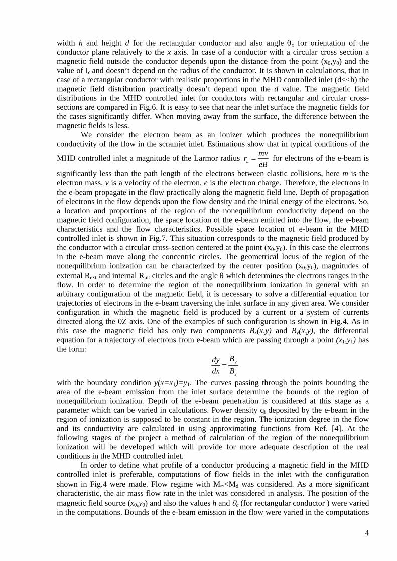
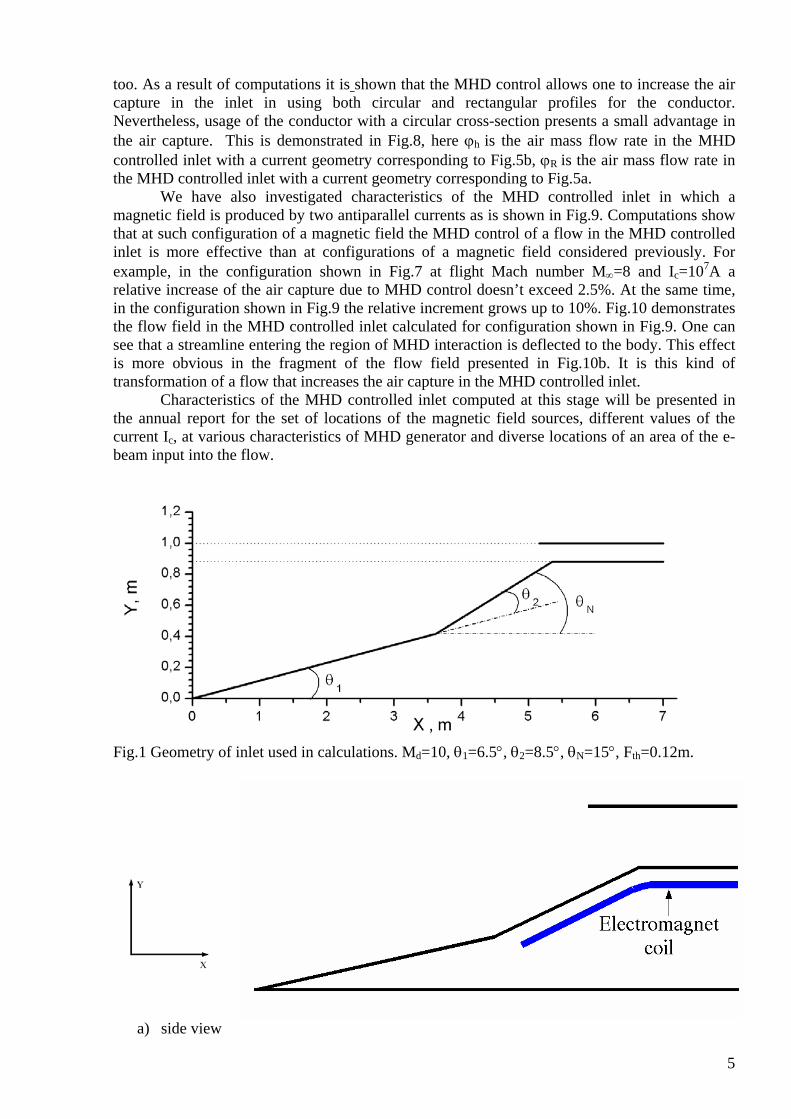
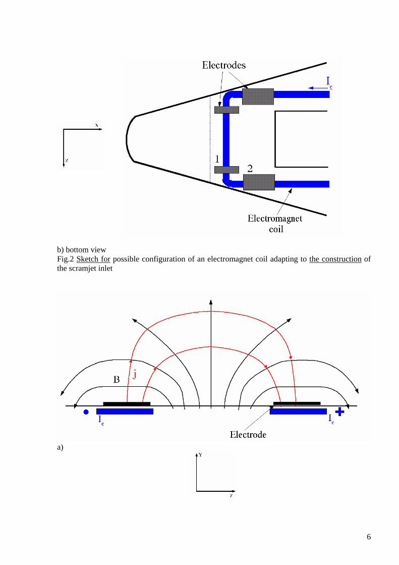
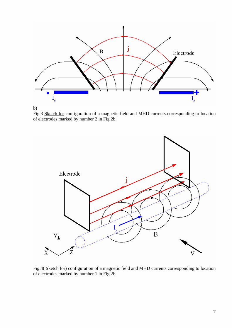
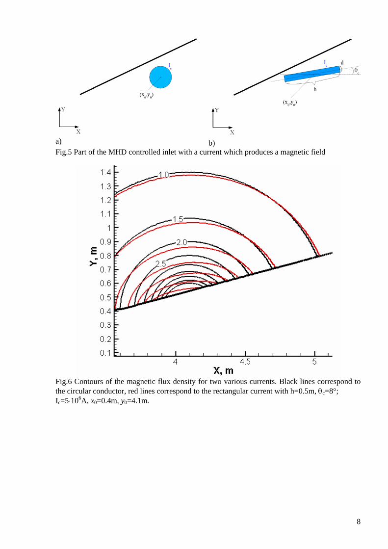
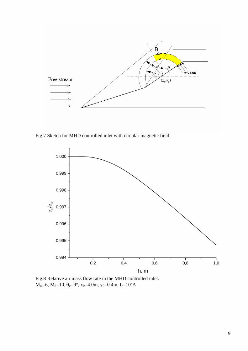
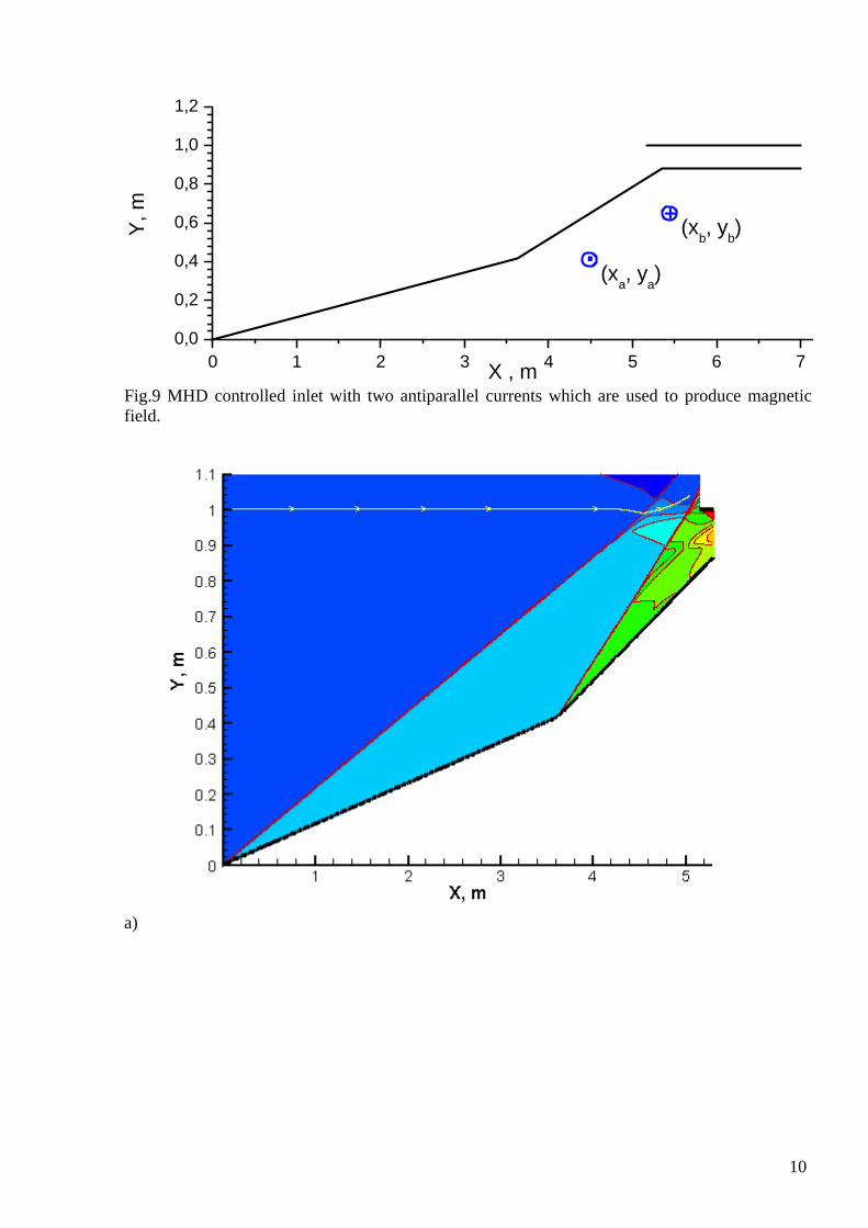
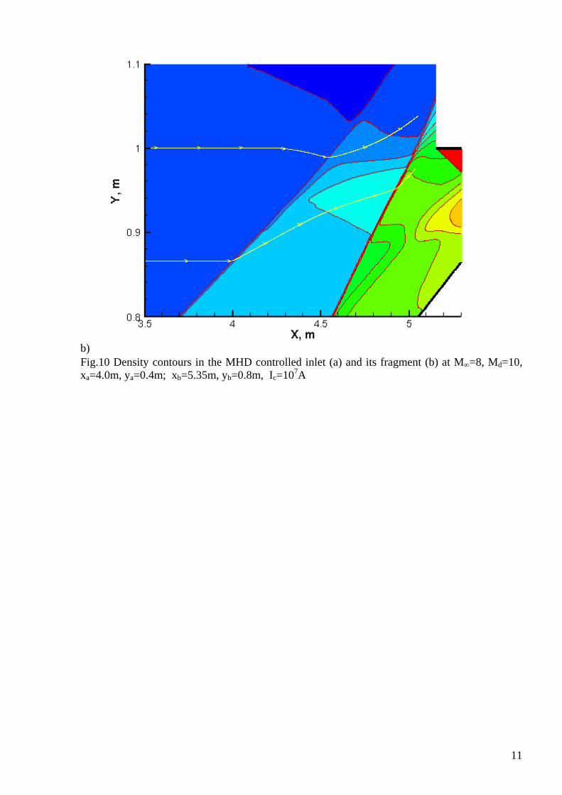
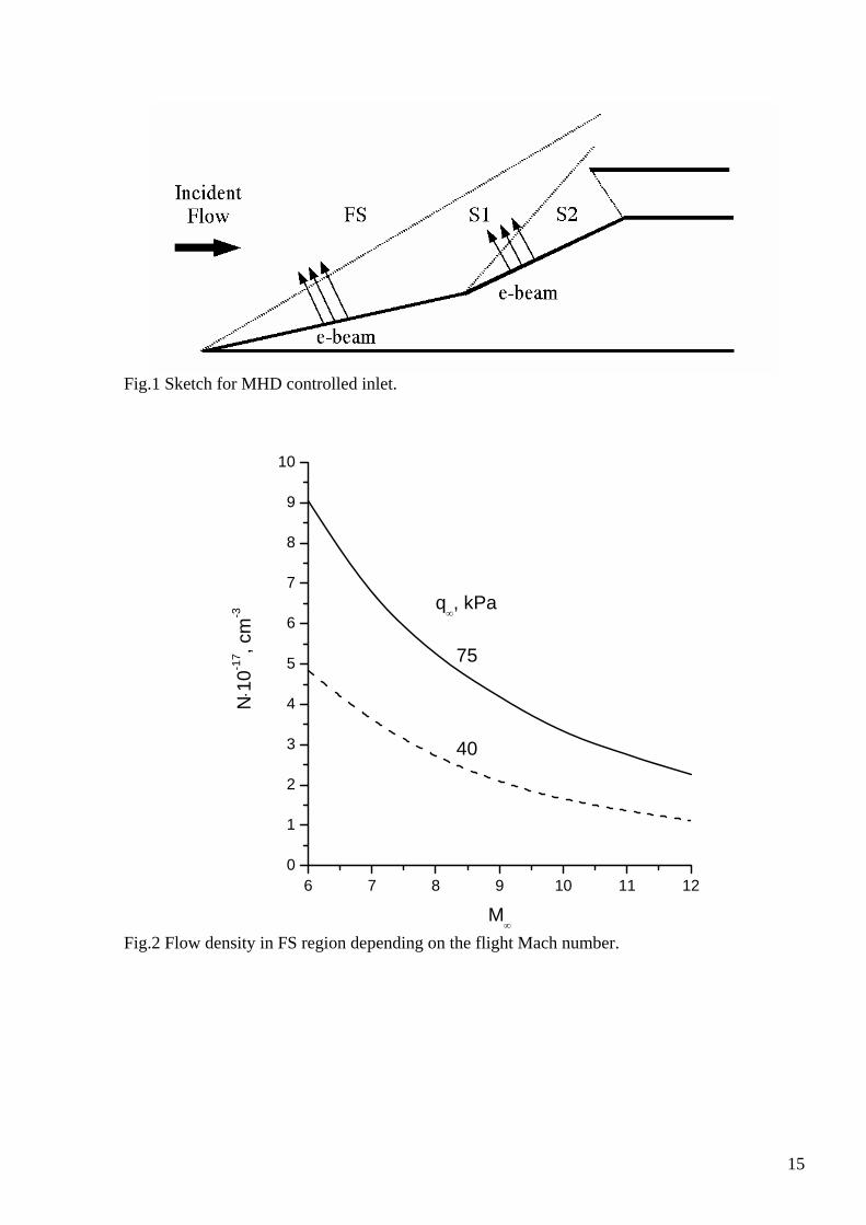
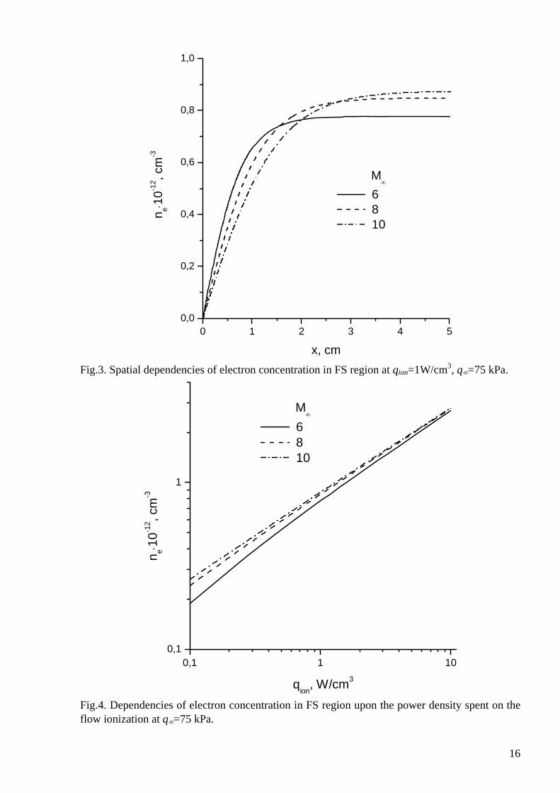
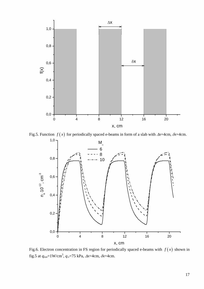
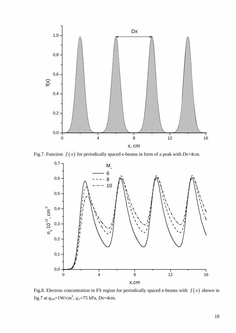
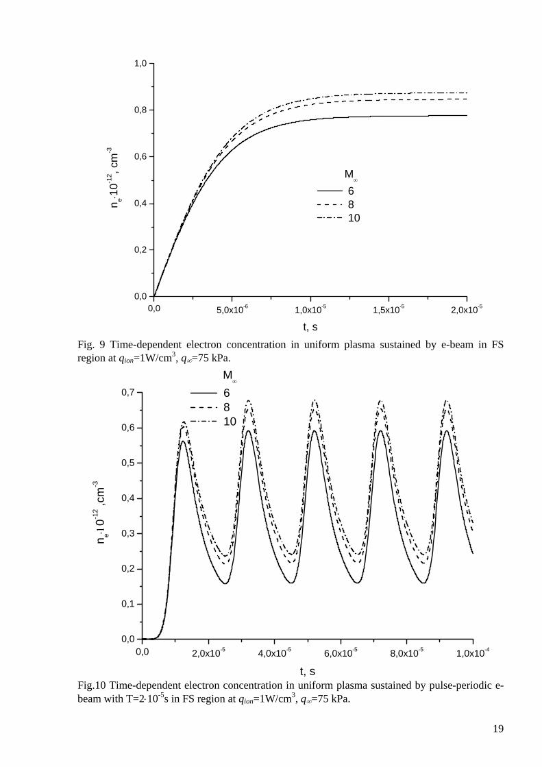
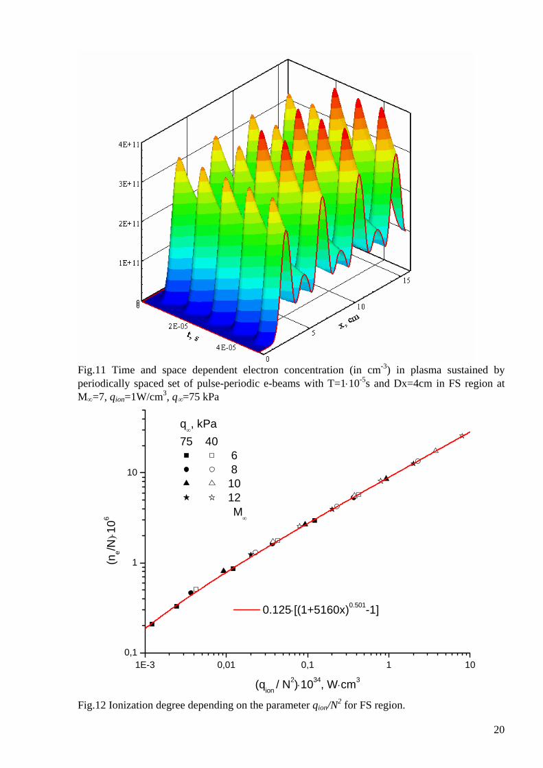
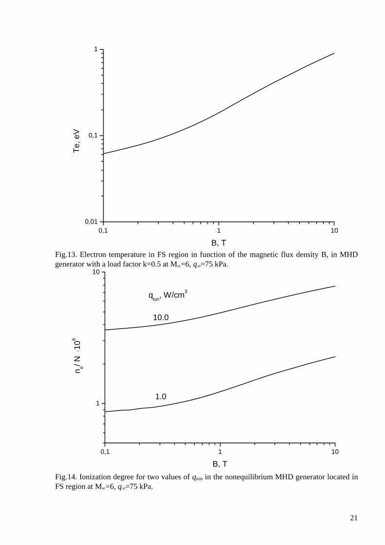
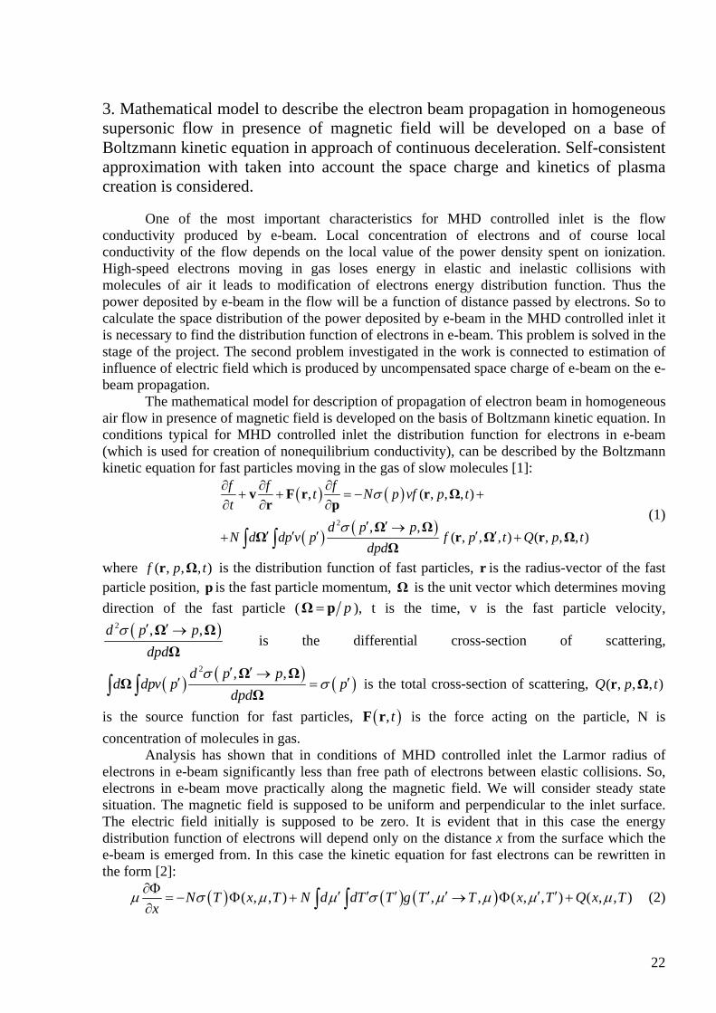
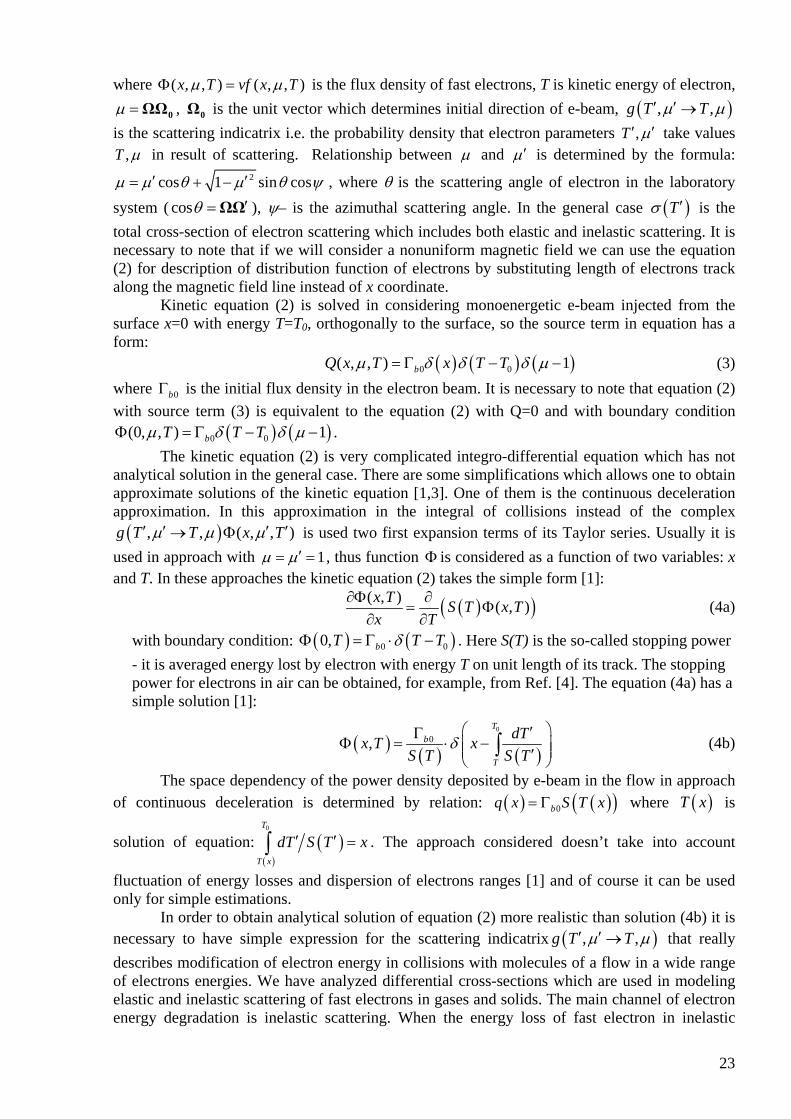
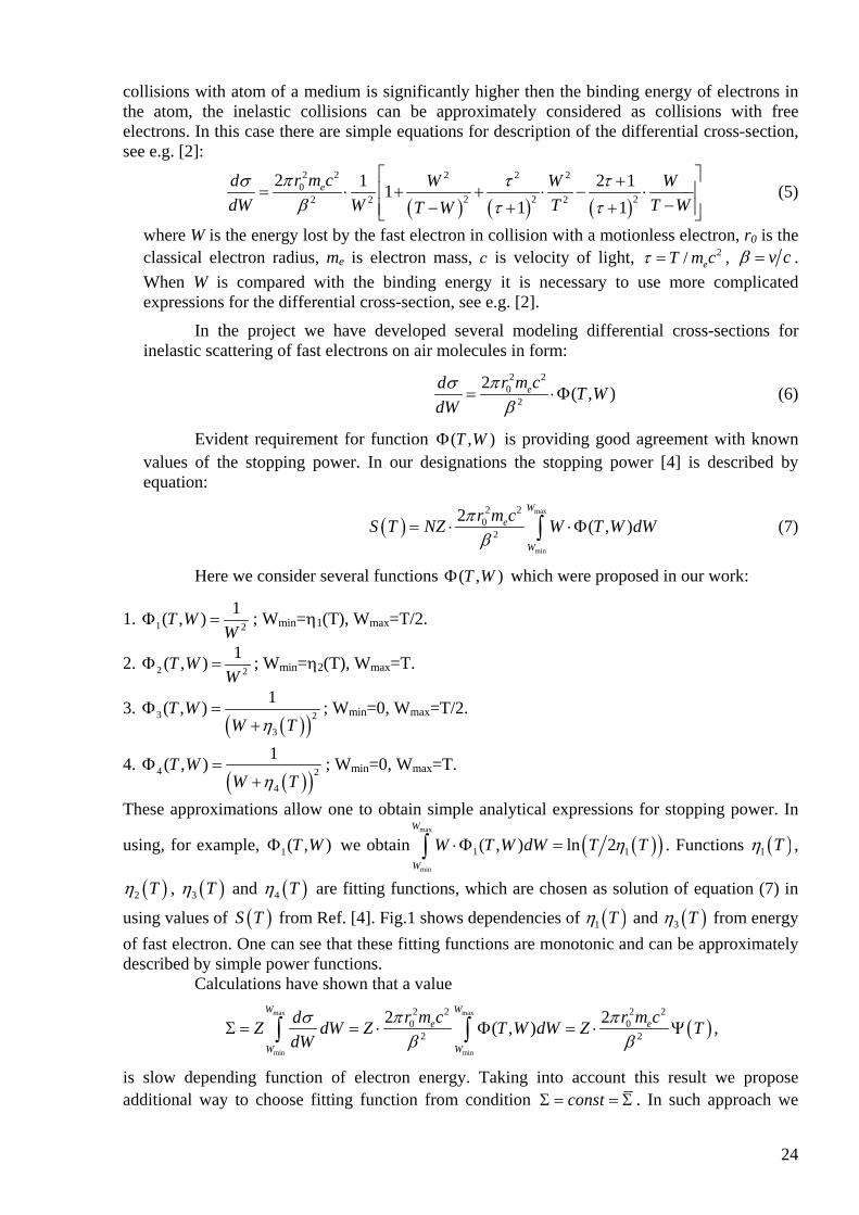
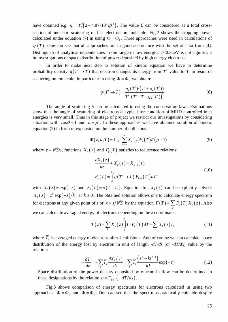
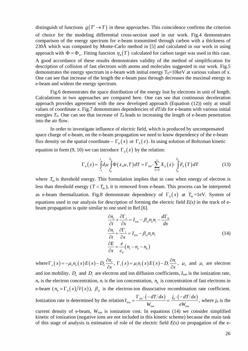
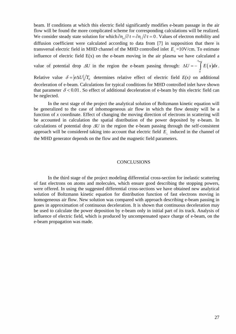
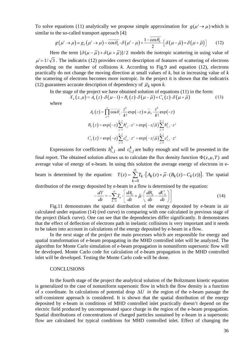
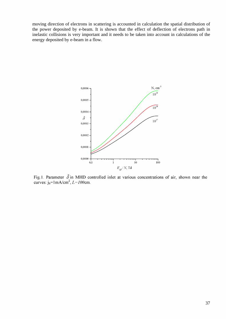

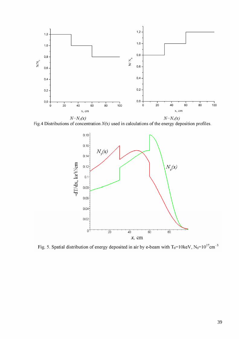
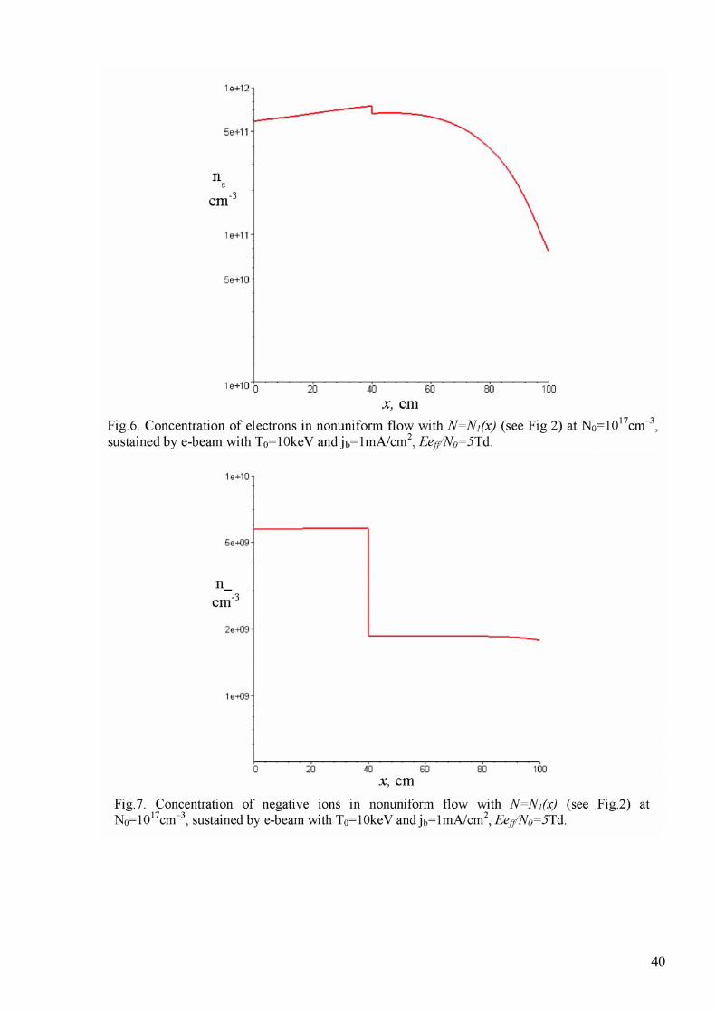
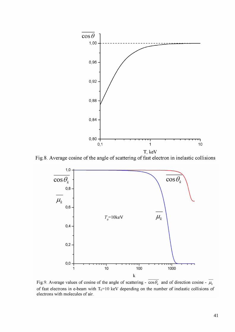
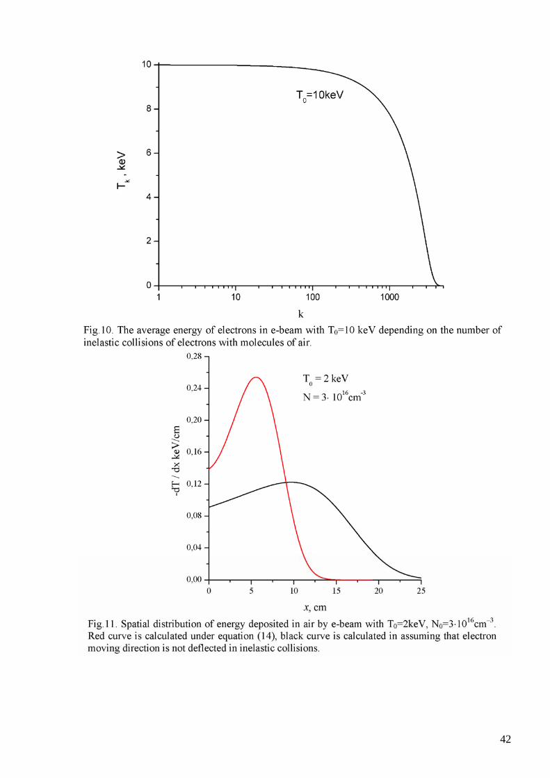
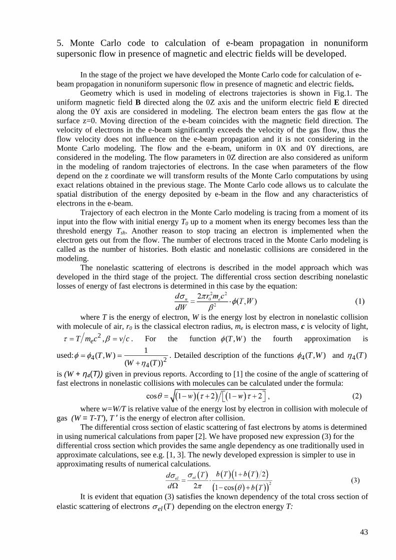
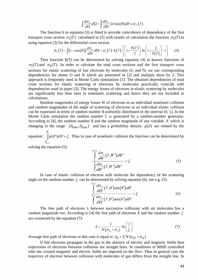

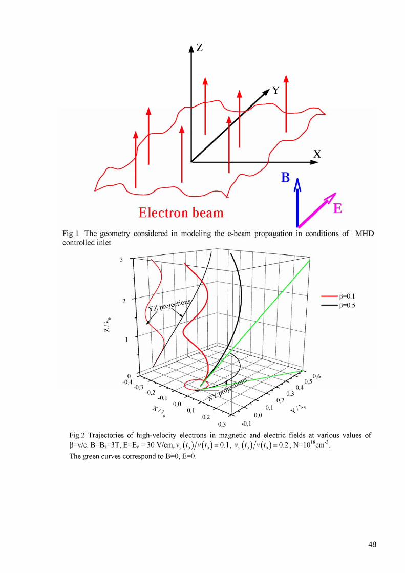
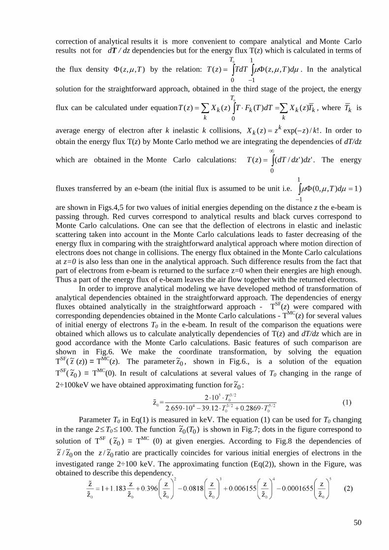
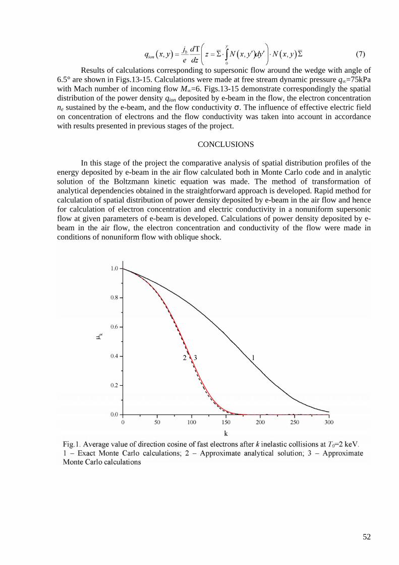
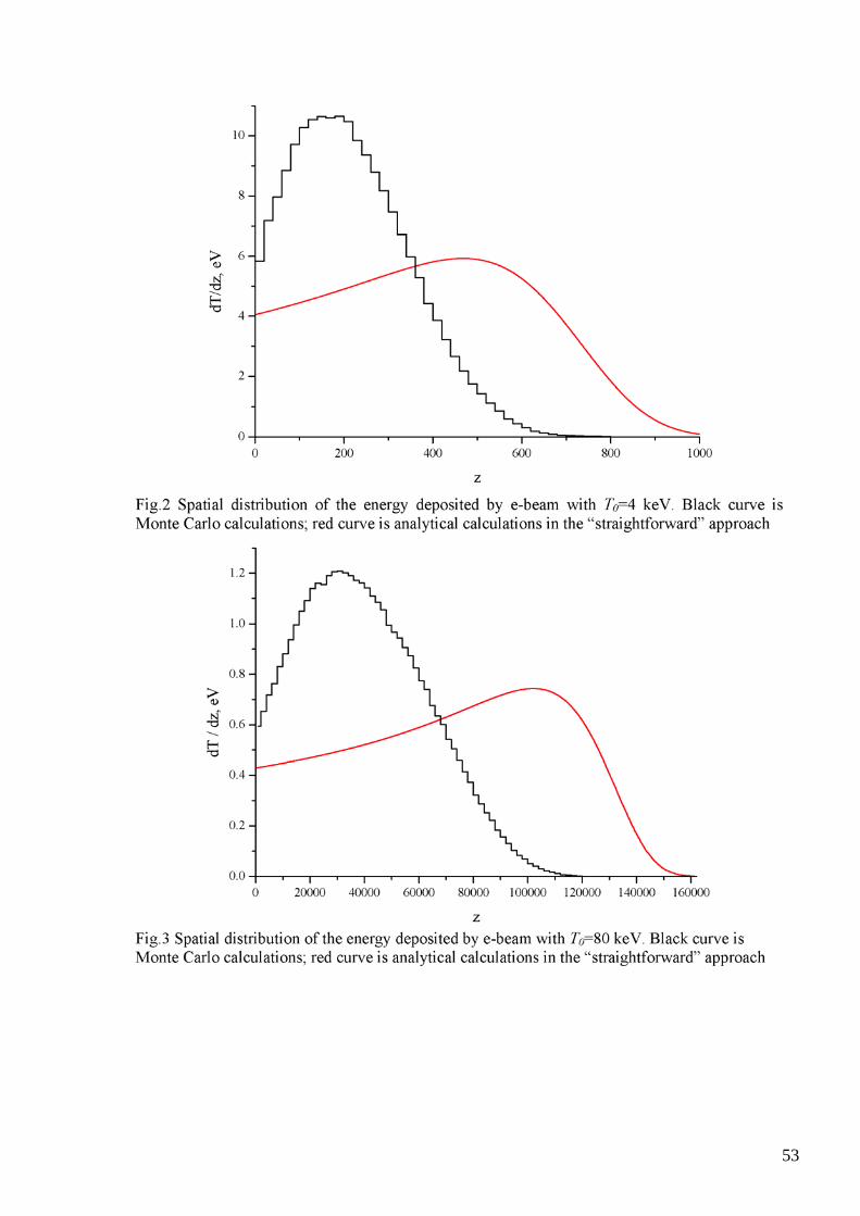
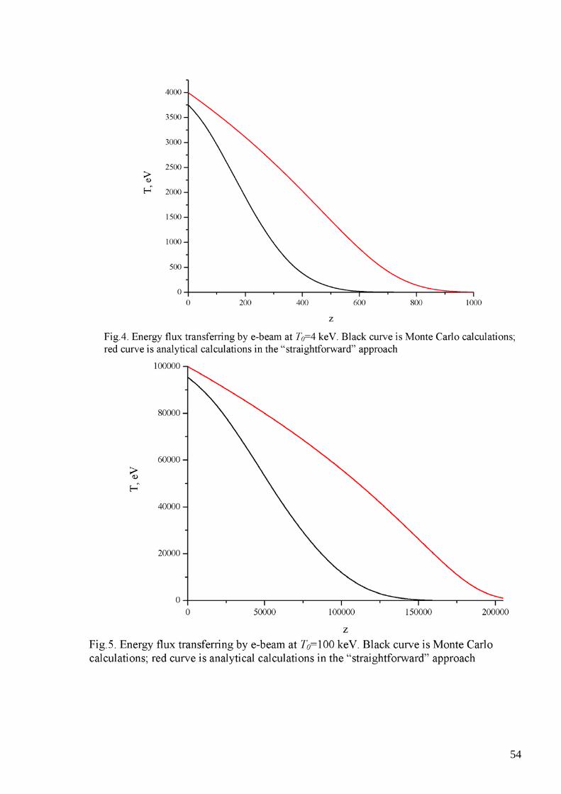

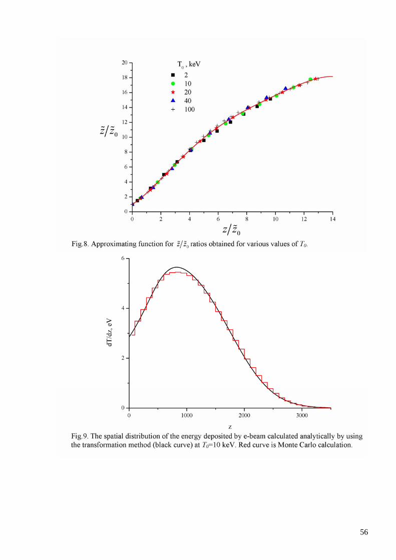
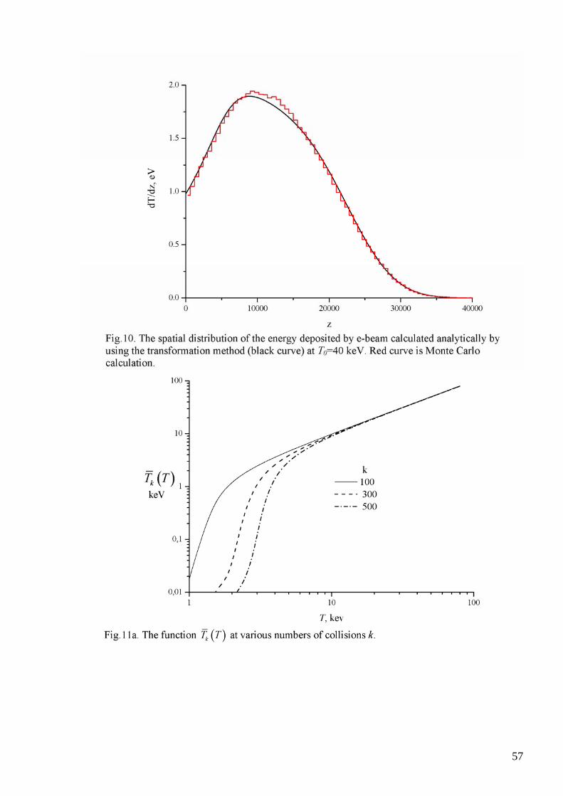
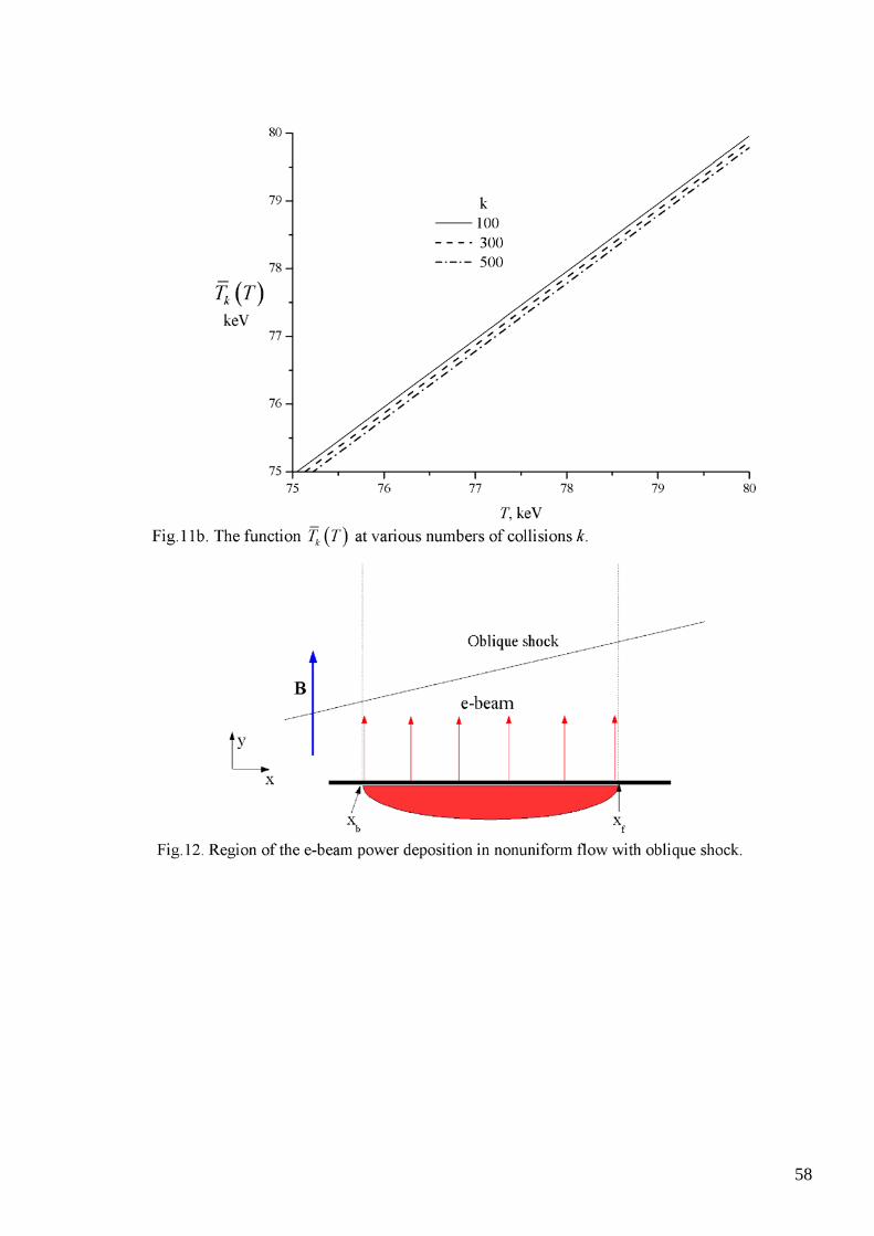
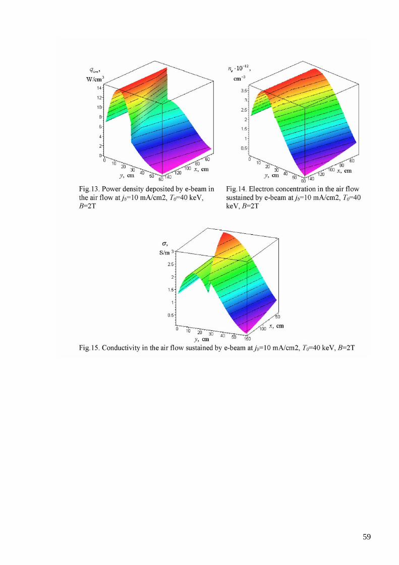
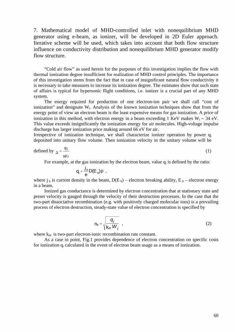
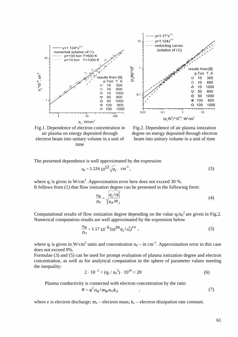
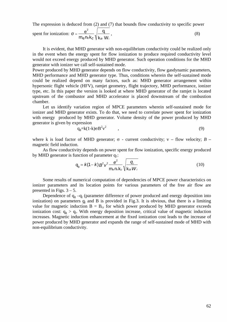
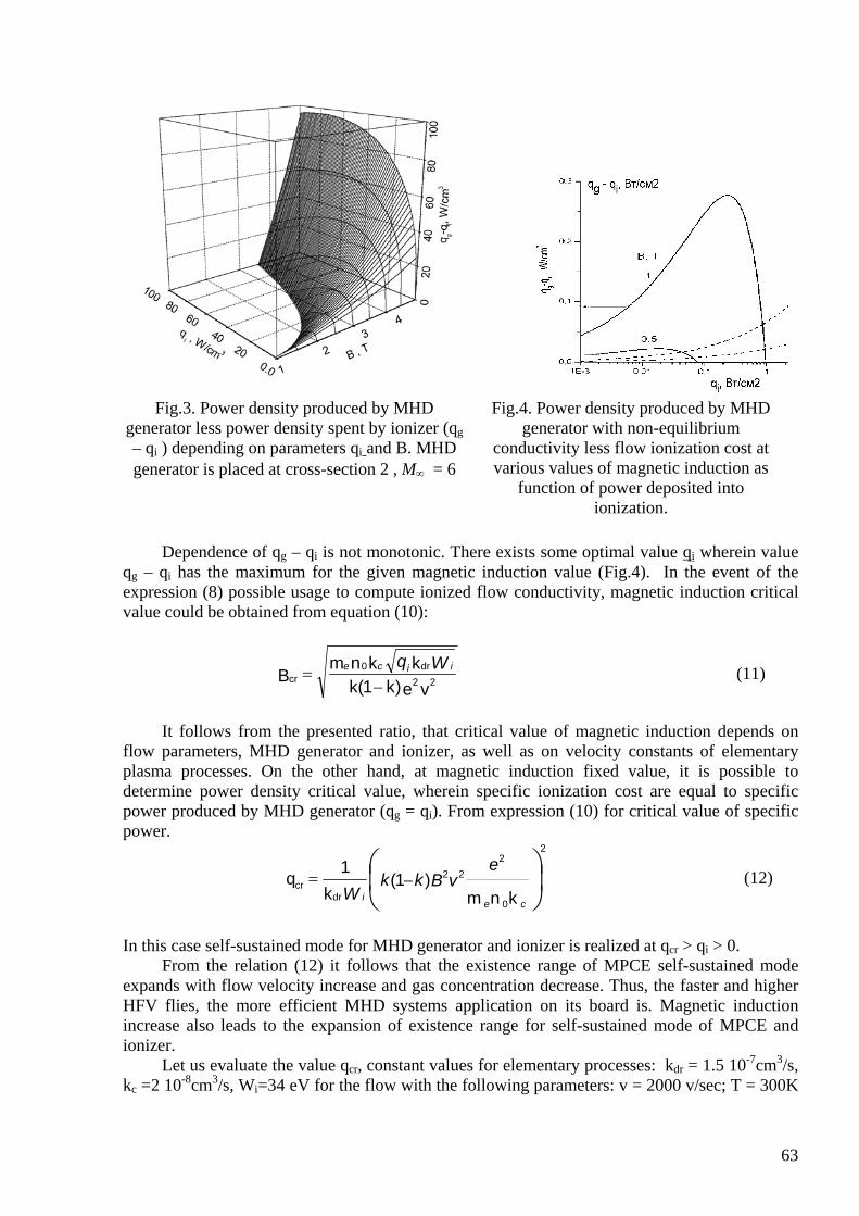
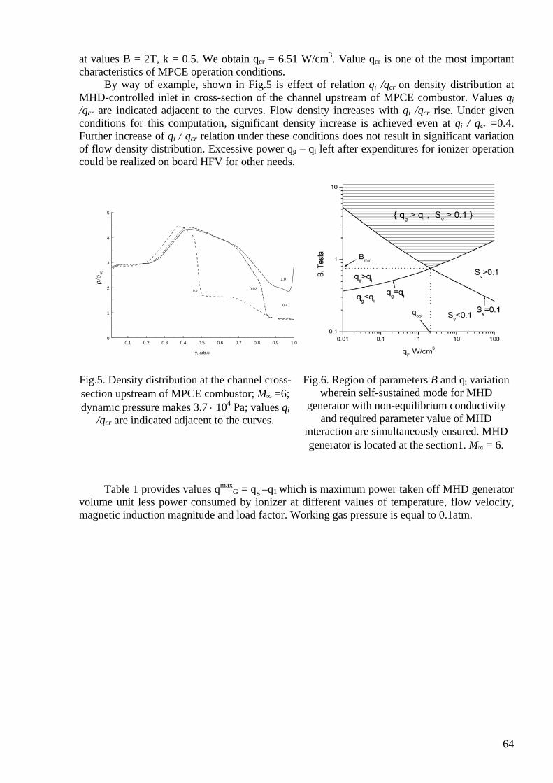
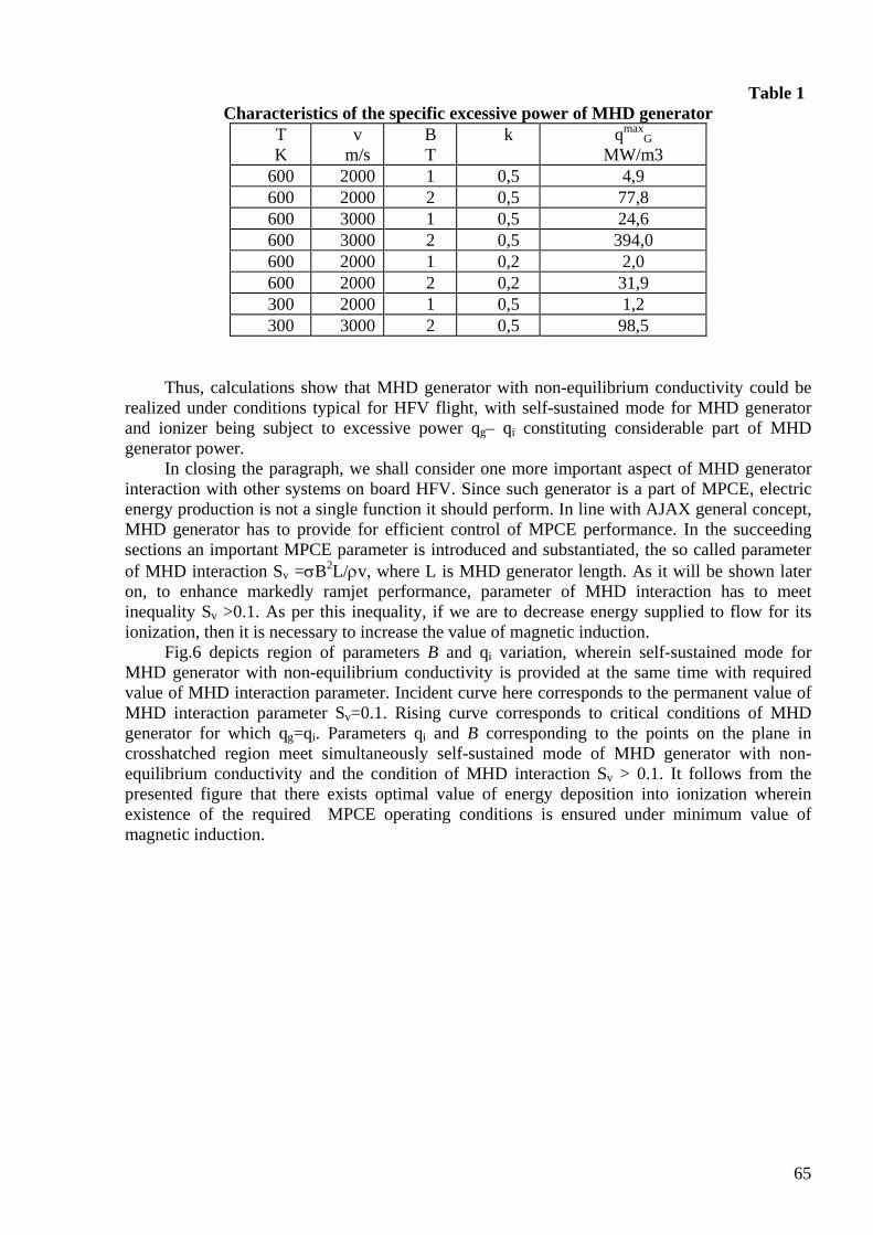
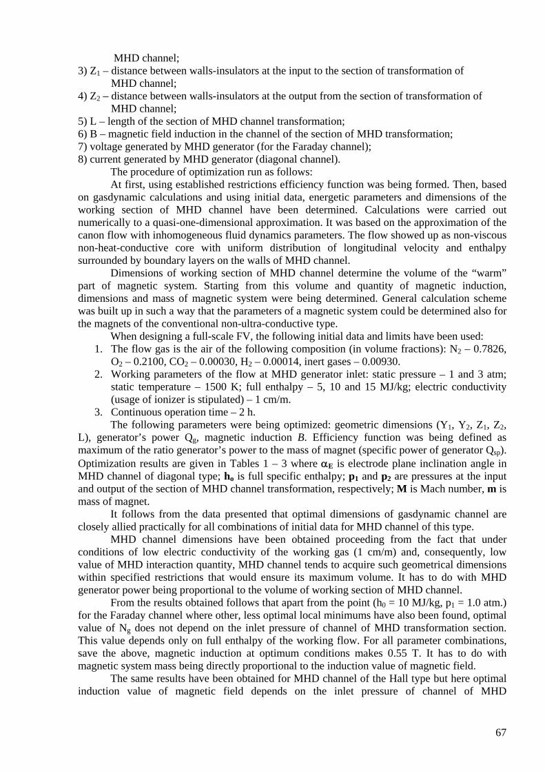
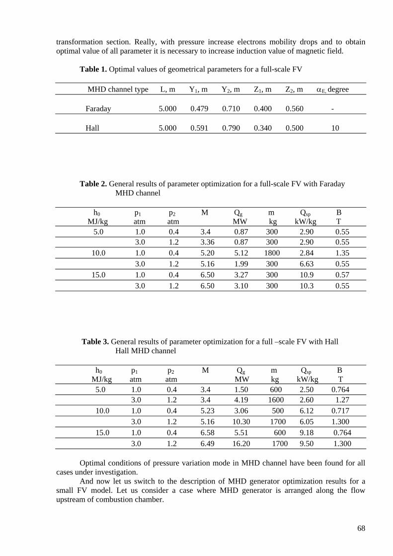
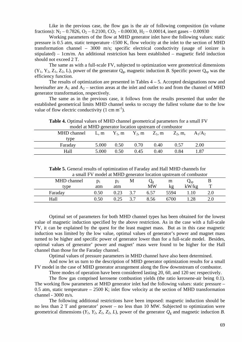
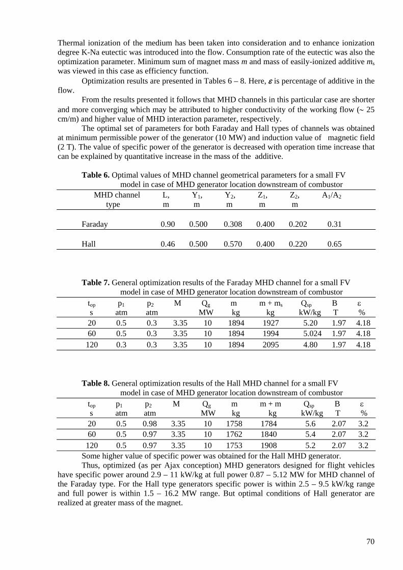


![Report on EOARD Grant FA8655-13-1-2147 MAYRHOFERThermal Conductivity Designed Hard Protective Thin Films Paul H. Mayrhofer EOARD Grant/Award FA8655-13-1-2147 2/6 properties [4]. Cr](https://static.documents.pub/doc/80x56/6012c8ff5a8dae165638cc28/report-on-eoard-grant-fa8655-13-1-2147-mayrhofer-thermal-conductivity-designed-hard.jpg)


