48
THE DANISH ACCIDENT INVESTIGATION BOARD The Aviation Unit Report HCLJ510-000721 Incident involving ATR72-212A Registration OY-CIN Bornholm Airport (EKRN) 27 January 2010
THE DANISH ACCIDENT INVESTIGATION BOARD The Aviation Unit
Report
HCLJ510-000721
Incident involving ATR72-212A Registration OY-CIN
Bornholm Airport (EKRN) 27 January 2010
TABLE OF CONTENTS
Synopsis ............................................................................................................................................ 1 Summary........................................................................................................................................... 1 1. Factual information............................................................................................................ 1 1.1 History of the flight............................................................................................................ 1 1.2 Injuries to persons .............................................................................................................. 3 1.3 Damage to aircraft.............................................................................................................. 3 1.4 Other damage ..................................................................................................................... 3 1.5 Personnel information ........................................................................................................ 3
1.5.1 Statement of the commander’s flying time........................................................... 3 1.5.2 License held by the commander ........................................................................... 4 1.5.3 The flight and duty time of the pilots (data selected by the AIB) ........................ 4
1.6 Aircraft information ........................................................................................................... 5 1.6.1 ATC flight plan (IDLA – Individual Delay (message)/27 1648) ......................... 5 1.6.2 Mass and balance.................................................................................................. 5 1.6.3 Operational flight plan (extract) ........................................................................... 6
1.7 Meteorological information ............................................................................................... 7 1.7.1 General ................................................................................................................. 7 1.7.2 Significant Weather Chart .................................................................................... 8 1.7.3 TAF....................................................................................................................... 9 1.7.4 METAR .............................................................................................................. 10 1.7.5 SNOWTAM ....................................................................................................... 11 1.7.6 Wind information ............................................................................................... 12
1.8 Aids to navigation ............................................................................................................ 16 1.9 Communications .............................................................................................................. 16 1.10 Aerodrome information.................................................................................................... 16
1.10.1 Overview of EKRN Airport (extract from AIP Denmark) ................................... 16 1.10.2 Approval of an arrester gear installation at EKRN ............................................... 16 1.10.3 NOTAM (extract) ................................................................................................. 18 1.10.4 The operator’s approach chart (VOR/DME approach to runway 29) ................... 18 1.10.5 Guidelines for the airport’s winter service (EKRN) ............................................. 18
1.11 Flight recorders ................................................................................................................ 18 1.12 Place of incident............................................................................................................... 19 1.13 Medical and pathological information ............................................................................. 20 1.14 Fire ................................................................................................................................... 20 1.15 Survival aspects ............................................................................................................... 20 1.16 Tests and research ............................................................................................................ 20
1.17 Organisational and management information .................................................................. 20
1.17.1 The Operator’s Operations Manual Part A (extract)............................................. 20 1.17.2 The Operator’s Standard Operating Procedures (SOP) (extract) .......................... 22 1.17.3 The operator’s Pilot Information Folder (PIF) (extract) ....................................... 24 1.17.4 ATR 72 Flight Crew Operating Manual (FCOM (extract)).................................. 26 1.17.5 Aircraft Flight Manual (AFM) (extract) ............................................................... 28
1.18 Additional information..................................................................................................... 28 1.19 Useful or effective investigation techniques .................................................................... 28 2. Analysis............................................................................................................................ 28 2.1 General ............................................................................................................................. 28 2.2. Flight planning ................................................................................................................. 28 2.3 Approach to EKRN.......................................................................................................... 29 2.4 Landing at EKRN ............................................................................................................ 30 3. Conclusion ....................................................................................................................... 32 3.1 Findings............................................................................................................................ 32 3.2 Factors.............................................................................................................................. 33 3.3 Summary .......................................................................................................................... 33 4. Recommendations............................................................................................................ 33 5. Enclosures ........................................................................................................................ 34 Enclosure 1 - Landing roll (overview picture)................................................................................ 35 Enclosure 2 - Landing roll (DFDR/ATC time)............................................................................... 36 Enclosure 3 - DFDR read out ......................................................................................................... 37 Enclosure 4 - DFDR readout .......................................................................................................... 38 Enclosure 5 - DFDR readout .......................................................................................................... 39 Enclosure 6 - DFDR readout .......................................................................................................... 40 Enclosure 7 - DFDR readout .......................................................................................................... 41 Enclosure 8 - EKRN overview picture (extract from AIP Denmark)............................................. 42 Enclosure 9 - The operator’s approach chart (VOR/DME RWY 29)............................................. 43 Enclosure 10 - EKRN guidelines for winter service....................................................................... 44
1
REPORT
HCLJ510-000721 Incident
Aircraft: ATR72-212A Registration: OY-CIN
Engines: 2 – PW 127F Flight: Scheduled flight, IFR
Crew: 4 – no injuries Passengers: 34 – no injuries
Location: Bornholm Airport (EKRN) Date and time: 27.1.2010 at 18:07 UTC
All times in this report are UTC.
Synopsis
The aviation unit of the Danish Accident Investigation Board (AIB) was notified of the incident from
the Area Control Centre at Copenhagen Airport, Kastrup (EKCH) on 27.1.2010 at 18:30.
The International Civil Aviation Organization (ICAO) and the French Accident Investigation Board
(Le Bureau d'Enquêtes et d'Analyses – BEA) were notified on 29.1.2010. The BEA appointed an
accredited representative to the investigation.
Summary
Landing under marginal crosswind conditions in combination with possible runway contamination
resulted in the aircraft running off the side of the runway (runway excursion).
The incident occurred in dark night and under instrument meteorological conditions (IMC).
The investigation has not resulted in any recommendations being made.
1. Factual information
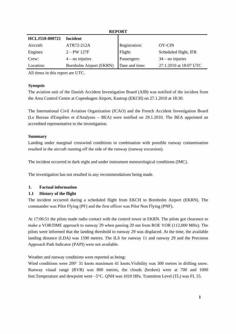
1.1 History of the flight
The incident occurred during a scheduled flight from EKCH to Bornholm Airport (EKRN). The
commander was Pilot Flying (PF) and the first officer was Pilot Non Flying (PNF).
At 17:06:51 the pilots made radio contact with the control tower at EKRN. The pilots got clearance to
make a VOR/DME approach to runway 29 when passing 20 nm from ROE VOR (112,000 MHz). The
pilots were informed that the landing threshold to runway 29 was displaced. At the time, the available
landing distance (LDA) was 1590 metres. The ILS for runway 11 and runway 29 and the Precision
Approach Path Indicator (PAPI) were not available.
Weather and runway conditions were reported as being:
Wind conditions were 200 31 knots maximum 41 knots.Visibility was 300 metres in drifting snow.
Runway visual range (RVR) was 800 metres, the clouds (broken) were at 700 and 1000
feet.Temperature and dewpoint were 5C. QNH was 1010 HPa. Transition Level (TL) was FL 55.
2
At approximately 17:02, the braking action coeficients on runway 29 were measured to be 48, 51 and
53. 50% of runway 29 was covered in 2 mm dry snow.
At 17:09:23, the control tower informed the pilots that the approach lights (high intensity) would be
switched on for the landing but that no lights would be switched on between the original landing
threshold and the displaced threshold for runway 29.
Immediately thereafter the pilots reported that due to the current RVR value of 800 metres they would
fly to Fauna holding pattern (334 KHz) in order to wait for a better RVR value. Later (at 17:19:10) the
pilots reported that a RVR value of 1000 metres was necessary in order for them to commence a
VOR/DME approach to runway 29.
At 17:26:20, the control tower informed the pilots that the RVR to runway 29 was 1100 metres. The
pilots responded that they would report back when they were ready to commence an approach.
At 17:27:50, wind conditions were reported to be 210 30 knots maximum 38 knots. RVR to runway
29 was 1200 metres.
At 17:28:46 the pilots reported to the control tower that they were ready to commence a VOR/DME
approach to runway 29. The control tower instructed them to wait since OY-CIN was number two for
landing. Number one for landing was a helicopter.
Once the helicopter had landed the pilots were cleared to commence a VOR/DME approach to runway
29. During the final approach the pilots received continuous wind information. At 17:41:26 and
17:42:02, wind conditions were reported to be 210 33 knots maximum 41 knots. The pilots decided to
make a go-around.
The pilots subsequently reported to the control tower that the aircraft had a crosswind limitation of 30
knots maximum.
After being informed that wind conditions at 17:48:10 and at 17:55:53 (210 were 29 knots maximum
40 knots / 200 29 knots maximum 37 knots), at 17:58:25, the pilots decided to attempt a new
VOR/DME approach to runway 29. The final approach speed determined by the pilots (correction for
icing and wind conditions) was 120 knots IAS, and the flaps of the aircraft were extended to flap
position 30. When passing radio altitude (RA) of 1000 feet, the aircraft was fully stabilized
(stabilized approach).
3
Wind conditions were reported constantly during the aircraft's final approach:
- At 18:00:44 (when passing 1995 feet RA / 200 28 knots maximum 34 knots)
- At 18:04:27 (when passing 1518 feet RA / 210 26 knots maximum 37 knots). The aircraft got
landing clearance.
- At 18:05:35 (when passing 951 feet RA / 210 28 knots maximum 37 knots)
- At 18:06:44 (when passing 255 feet RA / 210 30 knots maximum 35 knots).
During the landing roll the pilots noticed that the aircraft was beginning to veer to the left. PF
corrected this so that the aircraft was guided back to the centre line of the runway. Unexpectedly, the
pilots once again noticed that the aircraft was veering to the left. PF made maximum use of the wheel
brakes and full reversing of both engines. The aircraft continued to veer over towards the left side of
the runway. The pilots noticed that the nosewheel steering was not having any effect.
The aircraft ran over the side of the runway and came to a complete stop in the safety zone.
The pilots observed that there was no visible or noticeable damage and reported to the control tower
that the aircraft had run over the side of the runway and had remained in the safety zone.
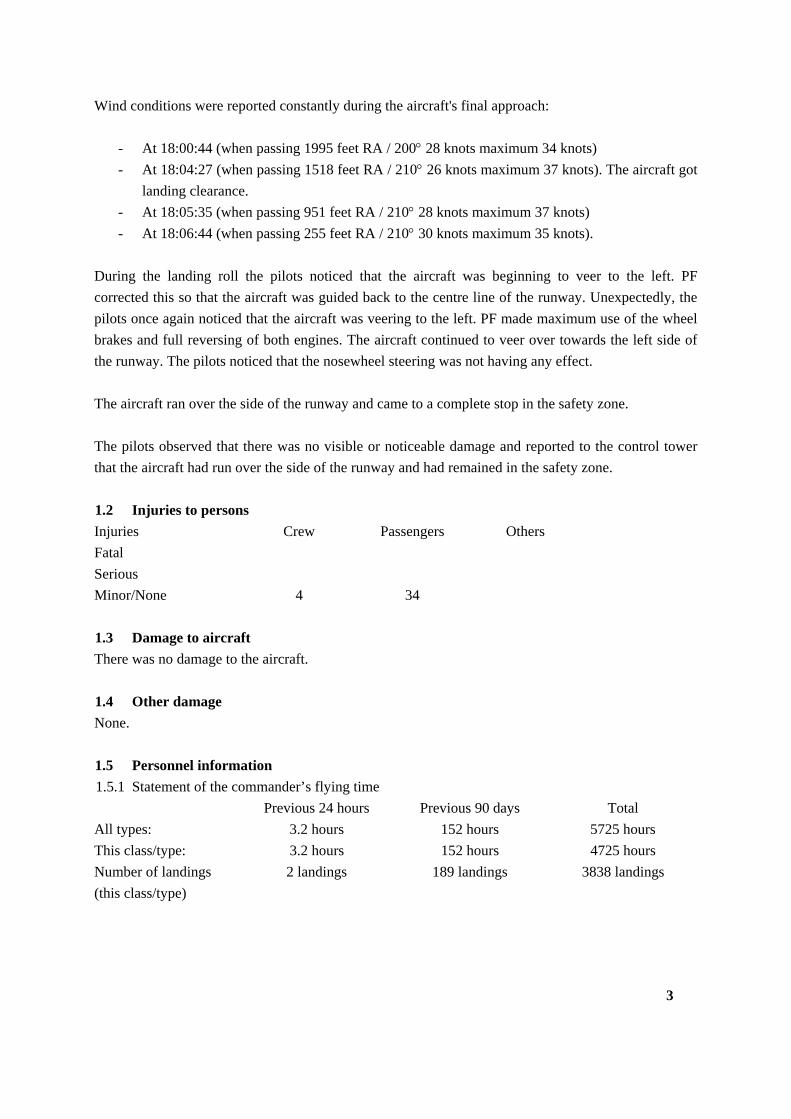
1.2 Injuries to persons
Injuries Crew Passengers Others
Fatal
Serious
Minor/None 4 34
1.3 Damage to aircraft
There was no damage to the aircraft.
1.4 Other damage
None.
1.5 Personnel information
1.5.1 Statement of the commander’s flying time
Previous 24 hours Previous 90 days Total
All types: 3.2 hours 152 hours 5725 hours
This class/type: 3.2 hours 152 hours 4725 hours
Number of landings
(this class/type)
2 landings 189 landings 3838 landings
4
1.5.2 License held by the commander
The commander was in possession of a valid Airline Transport Pilot License (ATPL (A)) with
appurtenant valid medical cerificate. The commander’s JAR-FCL ATR 72 rating was valid until
31.1.2011.
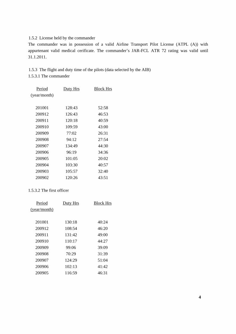
1.5.3 The flight and duty time of the pilots (data selected by the AIB)
1.5.3.1 The commander
Period
(year/month)
Duty Hrs Block Hrs
201001 128:43 52:58
200912 126:43 46:53
200911 120:18 40:59
200910 109:59 43:00
200909 77:02 26:31
200908 94:12 27:54
200907 134:49 44:30
200906 96:19 34:36
200905 101:05 20:02
200904 103:30 40:57
200903 105:57 32:40
200902 120:26 43:51
1.5.3.2 The first officer
Period
(year/month)
Duty Hrs Block Hrs
201001 130:18 40:24
200912 108:54 46:20
200911 131:42 49:00
200910 110:17 44:27
200909 99:06 39:09
200908 70:29 31:39
200907 124:29 51:04
200906 102:13 41:42
200905 116:59 46:31
1.6 Aircraft information
1.6.1 ATC flight plan (IDLA – Individual Delay (message)/27 1648)
The AIB has removed the operator’s name, the aircraft’s call sign and contact data (replaced with X)
Scheduled departure – EKCH: At 14:45
Scheduled arrival – EKRN: At 15:20
”NAV 908 271648 FF EKDKZQZE 271648 EUCHZMFP IFPLID AA75563373 EOBD 100127 IDLA CLS XXXXXX TYP AT72 /M RUL IS ADEP EKCH EOBT 1650 ADES EKRN CEQPT SRY SEQPT S EET 0026 TAS N0283 RFL F130 ROUTE N0283F130 BALOX L983 ROE DCT STS .................... RMK CONTACT NUMBER XXXXXXXXXX NAV .................... ALTRNT1 ESMS OPR XXX ORIGIN -NETWORKTYPE AFTN -FAC XXXXXXXX REG OYCIN RVR 300”
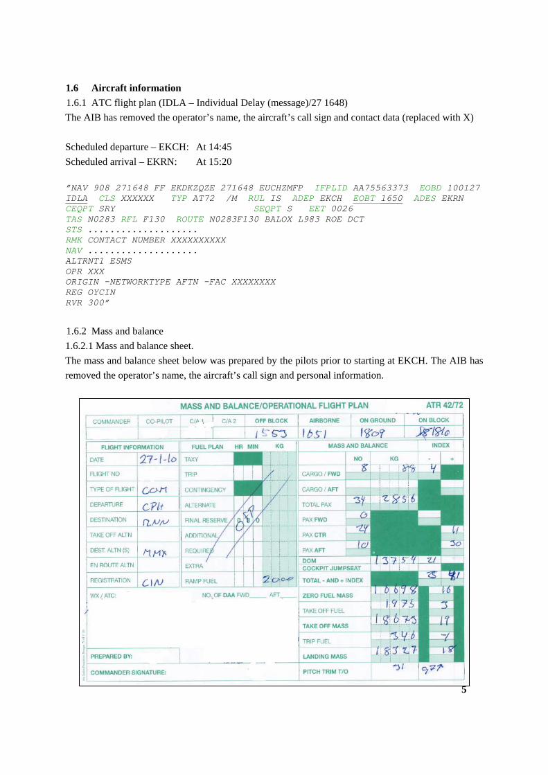
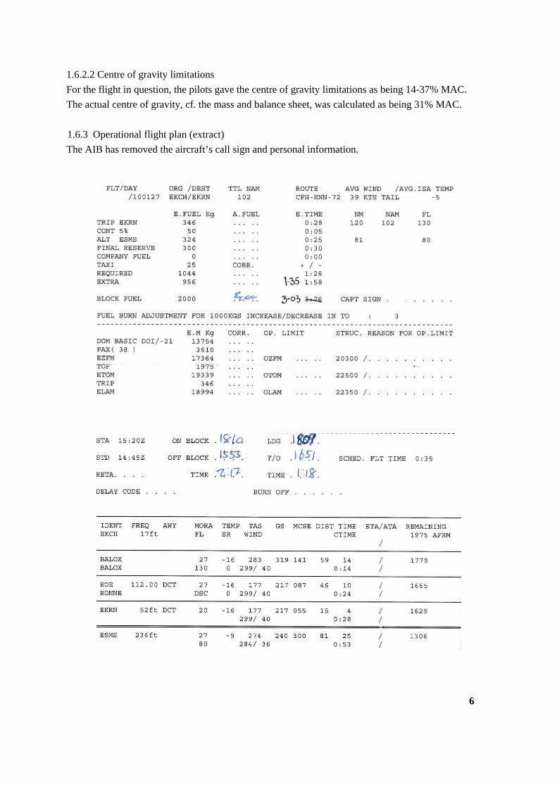
1.6.2 Mass and balance
1.6.2.1 Mass and balance sheet.
The mass and balance sheet below was prepared by the pilots prior to starting at EKCH. The AIB has
removed the operator’s name, the aircraft’s call sign and personal information.
5
1.6.2.2 Centre of gravity limitations
For the flight in question, the pilots gave the centre of gravity limitations as being 14-37% MAC.
The actual centre of gravity, cf. the mass and balance sheet, was calculated as being 31% MAC.
1.6.3 Operational flight plan (extract)
The AIB has removed the aircraft’s call sign and personal information.
6
1.7 Meteorological information
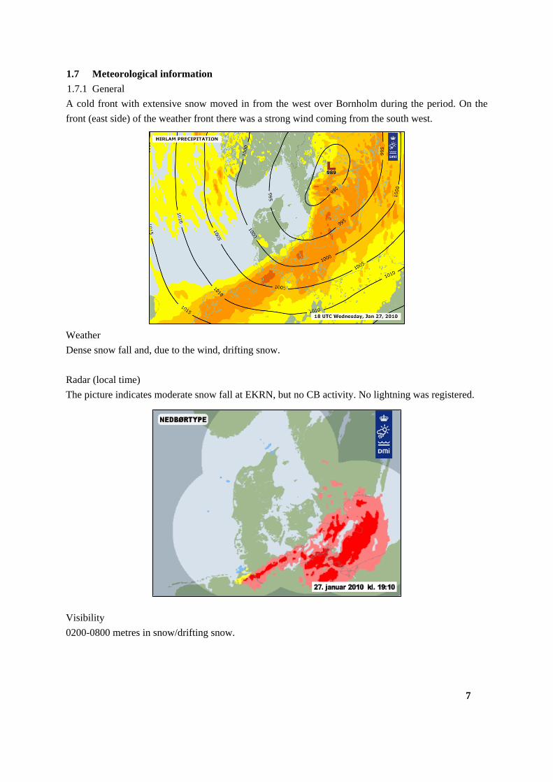
1.7.1 General
A cold front with extensive snow moved in from the west over Bornholm during the period. On the
front (east side) of the weather front there was a strong wind coming from the south west.
Weather
Dense snow fall and, due to the wind, drifting snow.
Radar (local time)
The picture indicates moderate snow fall at EKRN, but no CB activity. No lightning was registered.
Visibility
0200-0800 metres in snow/drifting snow.
7
Clouds
Dense frontal clouds, presumably with their base at around 100 feet, but, periodically vertical visibility
400-800 feet in snow fall. The top of the clouds was estimated to be at FL 180.
Icing
Light to moderate in clouds (i.e. 1000 feet to FL 100-120). Zero degrees on the surface.
Turbulence
Light to moderate mechanical turbulence below approximately 3000 feet. The low level turbulence
was primarily generated by the narrow strip of land/coast between the Baltic Sea and southern
Bornholm. Thus, the wind came from the water with the result that the flow was usually really laminar
and not particularly turbulent. However, the wind picked up on Bornholm’s southern coast over the
cliffs and could easily have caused turbulence locally at EKRN during the approach to both runways
11 and 29.
Windshear
The wind at approximately 2000 feet is estimated to be 220 degrees 45 knots. The mean wind speed
measured at EKRN was 24-26 knots. Thus, there was a windshear but not of a sufficient strength that
would normally cause problems. However, the periods between gusts/lulls at EKRN could have given
the impression of windshear conditions.
Ground wind
210 degrees, 24-26 knots, with wind gusts up to 40 knots.
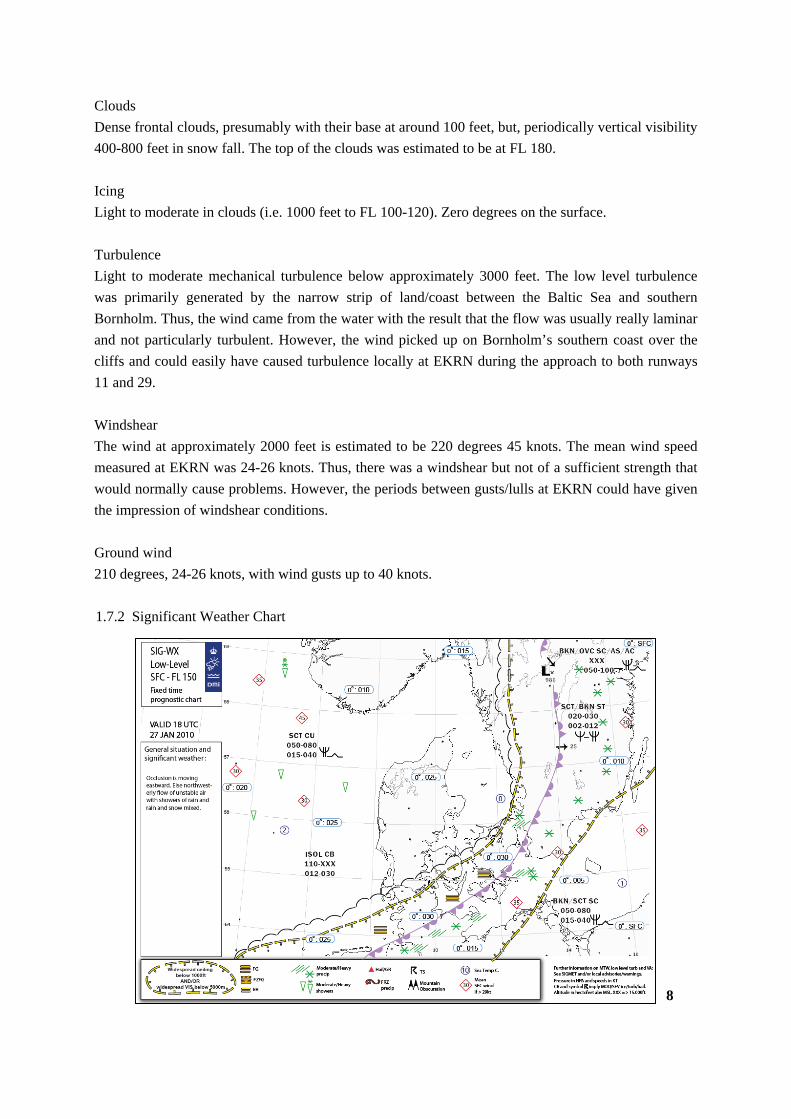
1.7.2 Significant Weather Chart
8
9
1.7.3 TAF
Text in blue indicates extracts from weather information used in flight planning, obtained by the pilots
at 14:21:55.
1.7.3.1 TAF for EKRN
271100 TAF-FC
ekrn 271140z 2712/2721 24018kt 0600 -fzra bkn004 tempo 2712/2713 24018g30kt 3000 br -sn
bkn010 becmg 2713/2715 22030kt 0800 sn blsn bkn006 tempo 2715/2718 22030g40kt 3000 -sn
bkn015=
271400 TAF-FC
ekrn 271440z 2715/2722 24022g35kt 0600 sn blsn vv004 tempo 2715/2720 23030g40kt 3000 -fzdz br
bkn010 becmg 2720/2722 1200 rasn br ovc002=
271400 TAF-FC AMD ekrn
271620z 2716/2722 24022g35kt 0500 sn blsn vv004 tempo 2716/2720 23030g40kt 3000 -fzdz br
bkn010 becmg 2720/2722 1200 rasn br ovc002=
271400 TAF-FC AMD ekrn
271655z 2716/2722 24022g35kt 0200 sn blsn vv004 tempo 2716/2720 23030g40kt 3000 -fzdz br
bkn010 becmg 2720/2722 1200 rasn br ovc002=
271700 TAF-FC ekrn
271740z 2718/2722 24022g35kt 0500 sn blsn vv004 tempo 2718/2720 23030g40kt 3000 -fzdz br
bkn010 becmg 2720/2722 1200 rasn br ovc002=
1.7.3.2 TAF for ESMS.
271130z 2712/28/12 23015G30KT 5000 –sn bkn010 tempo 2712/2722 0800 sn vv004 prob30
2712/2718 –fzdz becmg 2721/2723 29020kt bkn015 tempo 2723/2803 bkn006=
10
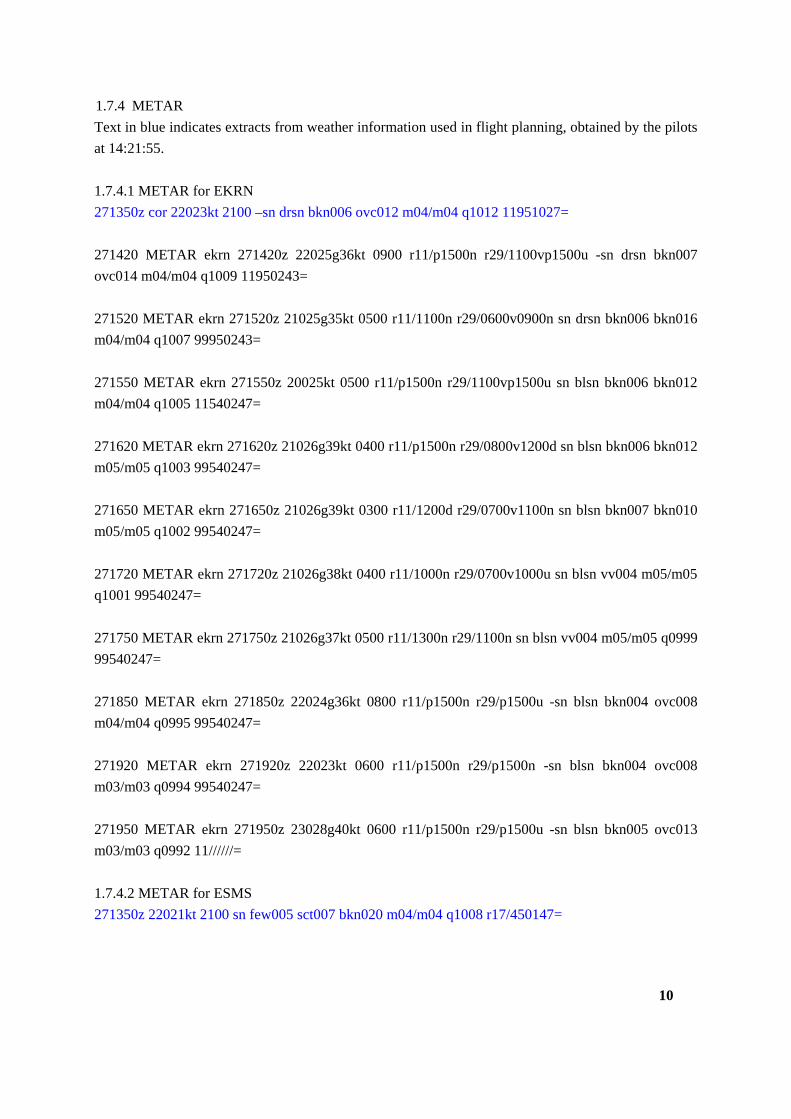
1.7.4 METAR
Text in blue indicates extracts from weather information used in flight planning, obtained by the pilots
at 14:21:55.
1.7.4.1 METAR for EKRN
271350z cor 22023kt 2100 –sn drsn bkn006 ovc012 m04/m04 q1012 11951027=
271420 METAR ekrn 271420z 22025g36kt 0900 r11/p1500n r29/1100vp1500u -sn drsn bkn007
ovc014 m04/m04 q1009 11950243=
271520 METAR ekrn 271520z 21025g35kt 0500 r11/1100n r29/0600v0900n sn drsn bkn006 bkn016
m04/m04 q1007 99950243=
271550 METAR ekrn 271550z 20025kt 0500 r11/p1500n r29/1100vp1500u sn blsn bkn006 bkn012
m04/m04 q1005 11540247=
271620 METAR ekrn 271620z 21026g39kt 0400 r11/p1500n r29/0800v1200d sn blsn bkn006 bkn012
m05/m05 q1003 99540247=
271650 METAR ekrn 271650z 21026g39kt 0300 r11/1200d r29/0700v1100n sn blsn bkn007 bkn010
m05/m05 q1002 99540247=
271720 METAR ekrn 271720z 21026g38kt 0400 r11/1000n r29/0700v1000u sn blsn vv004 m05/m05
q1001 99540247=
271750 METAR ekrn 271750z 21026g37kt 0500 r11/1300n r29/1100n sn blsn vv004 m05/m05 q0999
99540247=
271850 METAR ekrn 271850z 22024g36kt 0800 r11/p1500n r29/p1500u -sn blsn bkn004 ovc008
m04/m04 q0995 99540247=
271920 METAR ekrn 271920z 22023kt 0600 r11/p1500n r29/p1500n -sn blsn bkn004 ovc008
m03/m03 q0994 99540247=
271950 METAR ekrn 271950z 23028g40kt 0600 r11/p1500n r29/p1500u -sn blsn bkn005 ovc013
m03/m03 q0992 11//////=
1.7.4.2 METAR for ESMS
271350z 22021kt 2100 sn few005 sct007 bkn020 m04/m04 q1008 r17/450147=
11
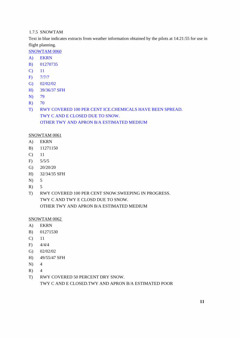
1.7.5 SNOWTAM
Text in blue indicates extracts from weather information obtained by the pilots at 14:21:55 for use in
flight planning.
SNOWTAM 0060
A) EKRN
B) 01270735
C) 11
F) 7/7/7
G) 02/02/02
H) 39/36/37 SFH
N) 79
R) 70
T) RWY COVERED 100 PER CENT ICE.CHEMICALS HAVE BEEN SPREAD.
TWY C AND E CLOSED DUE TO SNOW.
OTHER TWY AND APRON B/A ESTIMATED MEDIUM
SNOWTAM 0061
A) EKRN
B) 11271150
C) 11
F) 5/5/5
G) 20/20/20
H) 32/34/35 SFH
N) 5
R) 5
T) RWY COVERED 100 PER CENT SNOW.SWEEPING IN PROGRESS.
TWY C AND TWY E CLOSD DUE TO SNOW.
OTHER TWY AND APRON B/A ESTIMATED MEDIUM
SNOWTAM 0062
A) EKRN
B) 01271530
C) 11
F) 4/4/4
G) 02/02/02
H) 49/55/47 SFH
N) 4
R) 4
T) RWY COVERED 50 PERCENT DRY SNOW.
TWY C AND E CLOSED.TWY AND APRON B/A ESTIMATED POOR
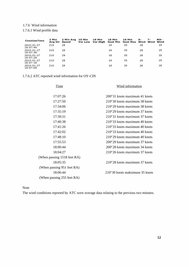
1.7.6 Wind information
1.7.6.1 Wind profile data
1.7.6.2 ATC reported wind information for OY-CIN
Time
Wind information
17:07:26 20031 knots maximum 41 knots
17:27:50 21030 knots maximum 38 knots
17:34:06 21029 knots maximum 38 knots
17:35:19 21029 knots maximum 37 knots
17:39:31 21031 knots maximum 37 knots
17:40:38 21033 knots maximum 40 knots
17:41:26 21033 knots maximum 40 knots
17:42:02 21033 knots maximum 40 knots
17:48:10 21029 knots maximum 40 knots
17:55:53 20029 knots maximum 37 knots
18:00:44 20028 knots maximum 34 knots
18:04:27
(When passing 1518 feet RA)
21026 knots maximum 37 knots
18:05:35
(When passing 951 feet RA)
21028 knots maximum 37 knots
18:06:44
(When passing 255 feet RA)
21030 knots maksimum 35 knots
Note
The wind conditions reported by ATC were average data relating to the previous two minutes.
12
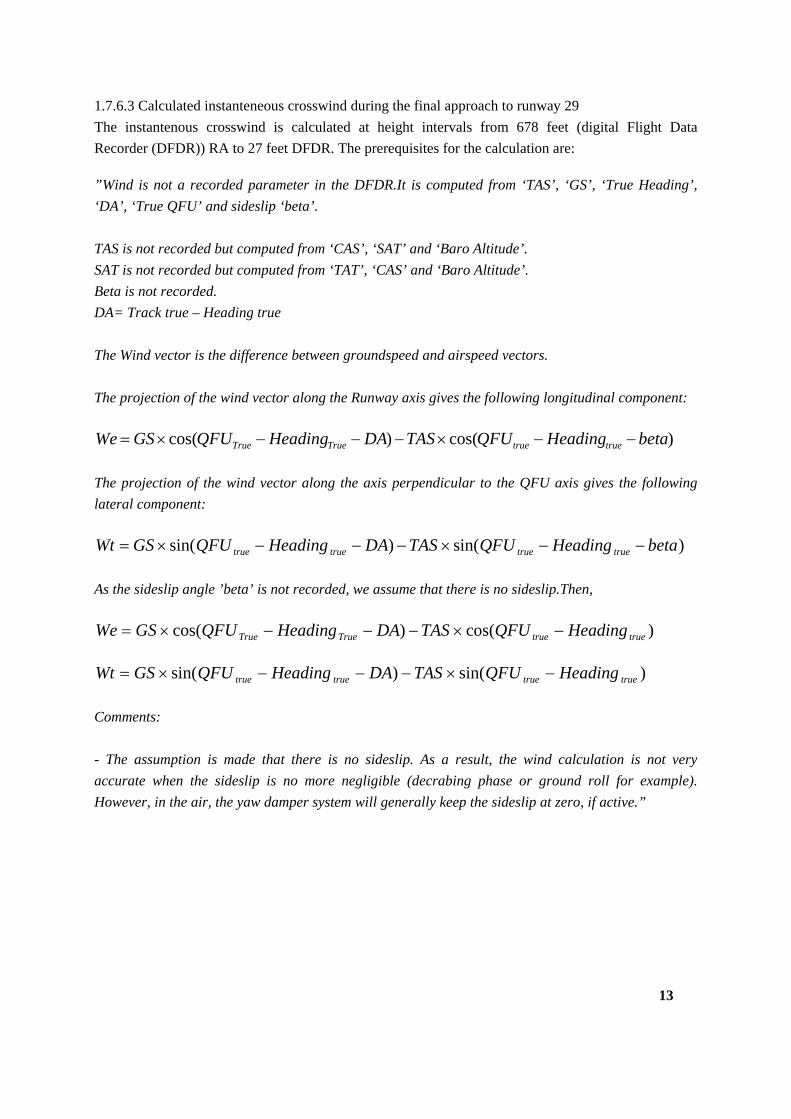
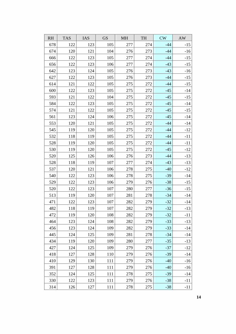
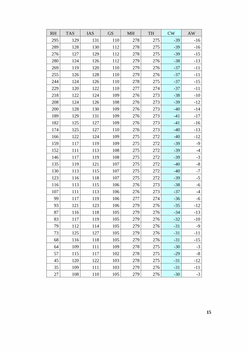
1.7.6.3 Calculated instanteneous crosswind during the final approach to runway 29
The instantenous crosswind is calculated at height intervals from 678 feet (digital Flight Data
Recorder (DFDR)) RA to 27 feet DFDR. The prerequisites for the calculation are:
”Wind is not a recorded parameter in the DFDR.It is computed from ‘TAS’, ‘GS’, ‘True Heading’,
‘DA’, ‘True QFU’ and sideslip ‘beta’.
TAS is not recorded but computed from ‘CAS’, ‘SAT’ and ‘Baro Altitude’.
SAT is not recorded but computed from ‘TAT’, ‘CAS’ and ‘Baro Altitude’.
Beta is not recorded.
DA= Track true – Heading true
The Wind vector is the difference between groundspeed and airspeed vectors.
The projection of the wind vector along the Runway axis gives the following longitudinal component:
)cos()cos( betaHeadingQFUTASDAHeadingQFUGSWe truetrueTrueTrue
The projection of the wind vector along the axis perpendicular to the QFU axis gives the following
lateral component:
)sin()sin( betaHeadingQFUTASDAHeadingQFUGSWt truetruetruetrue
As the sideslip angle ’beta’ is not recorded, we assume that there is no sideslip.Then,
)cos()cos( truetrueTrueTrue HeadingQFUTASDAHeadingQFUGSWe
)sin()sin( truetruetruetrue HeadingQFUTASDAHeadingQFUGSWt
Comments:
- The assumption is made that there is no sideslip. As a result, the wind calculation is not very
accurate when the sideslip is no more negligible (decrabing phase or ground roll for example).
However, in the air, the yaw damper system will generally keep the sideslip at zero, if active.”
13
14
RH TAS IAS GS MH TH CW AW
678 122 123 105 277 274 -44 -15
674 120 121 104 276 273 -44 -16
666 122 123 105 277 274 -44 -15
656 122 123 106 277 274 -43 -15
642 123 124 105 276 273 -43 -16
627 122 123 105 276 273 -44 -15
614 121 122 105 275 272 -44 -15
600 122 123 105 275 272 -45 -14
593 121 122 104 275 272 -45 -15
584 122 123 105 275 272 -45 -14
574 121 122 105 275 272 -45 -15
561 123 124 106 275 272 -45 -14
553 120 121 105 275 272 -44 -14
545 119 120 105 275 272 -44 -12
532 118 119 105 275 272 -44 -11
528 119 120 105 275 272 -44 -11
530 119 120 105 275 272 -45 -12
520 125 126 106 276 273 -44 -13
528 118 119 107 277 274 -43 -13
537 120 121 106 278 275 -40 -12
540 122 123 106 278 275 -39 -14
529 122 123 106 279 276 -38 -15
520 122 123 107 280 277 -36 -15
513 119 120 107 281 278 -34 -14
471 122 123 107 282 279 -32 -14
482 118 119 107 282 279 -32 -13
472 119 120 108 282 279 -32 -11
464 123 124 108 282 279 -33 -13
456 123 124 109 282 279 -33 -14
445 124 125 109 281 278 -34 -14
434 119 120 109 280 277 -35 -13
427 124 125 109 279 276 -37 -12
418 127 128 110 279 276 -39 -14
410 129 130 111 279 276 -40 -16
391 127 128 111 279 276 -40 -16
352 124 125 111 278 275 -39 -14
330 122 123 111 279 276 -38 -11
314 126 127 111 278 275 -38 -11
15
RH TAS IAS GS MH TH CW AW
295 129 131 110 278 275 -39 -16
289 128 130 112 278 275 -39 -16
276 127 129 112 278 275 -39 -15
280 124 126 112 279 276 -38 -13
269 119 120 110 279 276 -37 -11
255 126 128 110 279 276 -37 -11
244 124 126 110 278 275 -37 -15
229 120 122 110 277 274 -37 -11
218 122 124 109 276 273 -38 -10
208 124 126 108 276 273 -39 -12
200 128 130 109 276 273 -40 -14
189 129 131 109 276 273 -41 -17
182 125 127 109 276 273 -41 -16
174 125 127 110 276 273 -40 -13
166 122 124 109 275 272 -40 -12
159 117 119 109 275 272 -39 -9
152 111 113 108 275 272 -39 -4
146 117 119 108 275 272 -39 -3
135 119 121 107 275 272 -40 -8
130 113 115 107 275 272 -40 -7
123 116 118 107 275 272 -39 -5
116 113 115 106 276 273 -38 -6
107 111 113 106 276 273 -37 -4
99 117 119 106 277 274 -36 -6
93 121 123 106 279 276 -35 -12
87 116 118 105 279 276 -34 -13
83 117 119 105 279 276 -32 -10
79 112 114 105 279 276 -31 -9
73 125 127 105 279 276 -31 -11
68 116 118 105 279 276 -31 -15
64 109 111 109 278 275 -30 -3
57 115 117 102 278 275 -29 -8
45 120 122 103 278 275 -31 -12
35 109 111 103 279 276 -31 -11
27 108 110 105 279 276 -30 -3
16
1.8 Aids to navigation
Due to work in progress on the runway, NOTAM was issued for EKRN. The work in progress on the
runway meant that, for instance, the ILS for runways 11 and 29 were withdrawn. See NOTAM under
1.10.
1.9 Communications
A transcript of the voice communication for the EKRN control tower (118.325 MHz) was prepared.
The voice communication was of a good quality and was used in the investigation.
1.10 Aerodrome information
1.10.1 Overview of EKRN Airport (extract from AIP Denmark)
See enclosure 8.
1.10.2 Approval of an arrester gear installation at EKRN
On 7.1.2010, Bornholm Airport submitted a request to the CAA-DK for permission to initiate
establishment of an arrester gear installation. The issue of NOTAM was a sub-element of the work
activities.
Below is an extract of the airport’s application. The CAA-DK approved the establishment activities on
8.1.2010. The approval was conditional upon the measures to be taken by the airport, cf. letter of
7.1.2010 and BL 3-12 being complied with.
The below text is translated into English by the Danish AIB.
“ NOTAM is issued in connection with the work activity.
Threshold RWY 11 displaced 335 m due to WIP.
Declared distance:
RWY 11 TORA TODA ASDA LDA 1590 M
RWY 29 TORA TODA ASDA LDA 1590 M
ILS RWY 11 and approach lights and PAPI RWY 11 withdrawn
ILS RWY 29 withdrawn.
17
Threshold RWY 29 displaced 410 m due to WIP.
Declared distance:
RWY 29 TORA TODA ASDA LDA 1665 M
RWY 11 TORA TODA ASDA 1725 M LDA 1665 M
ILS RWY 29 and approach lights and PAPI RWY 29 withdrawn
ILS RWY 11 withdrawn.
The lighting system is to be adapted so that all lighting behind the displaced threshold in question is
either dimmed or interrupted, just as the ILS segment is interrupted.
The displaced threshold will consist of 2 rows with 5 high intensity threshold/runway end lights,
placed in such a way that there is a gap of 22 metres between the two rows.
The lights are to be distributed evenly beyond the shoulders (3 on the runway, 2 in the grass). Further
to this, red/white day markings indicating the threshold are to be placed in the grass.
White cross lines are to be established to mark the displaced threshold. A white cross is to be painted
on to camouflage the existing threshold which must not be used, just as other markings are to be
blurred to the extent necessary. The shortened portion of runway 29 is to be marked with a white
cross. With regard to runway 11, arrow markings are to be used in accordance with Annex 14, point
5,2,4,10.
The condition of the runway will be checked according to the normal runway inspection sheet.”
1.10.3 NOTAM (extract)
The NOTAM below was included as a sub-element of the pilot’s flight planning.
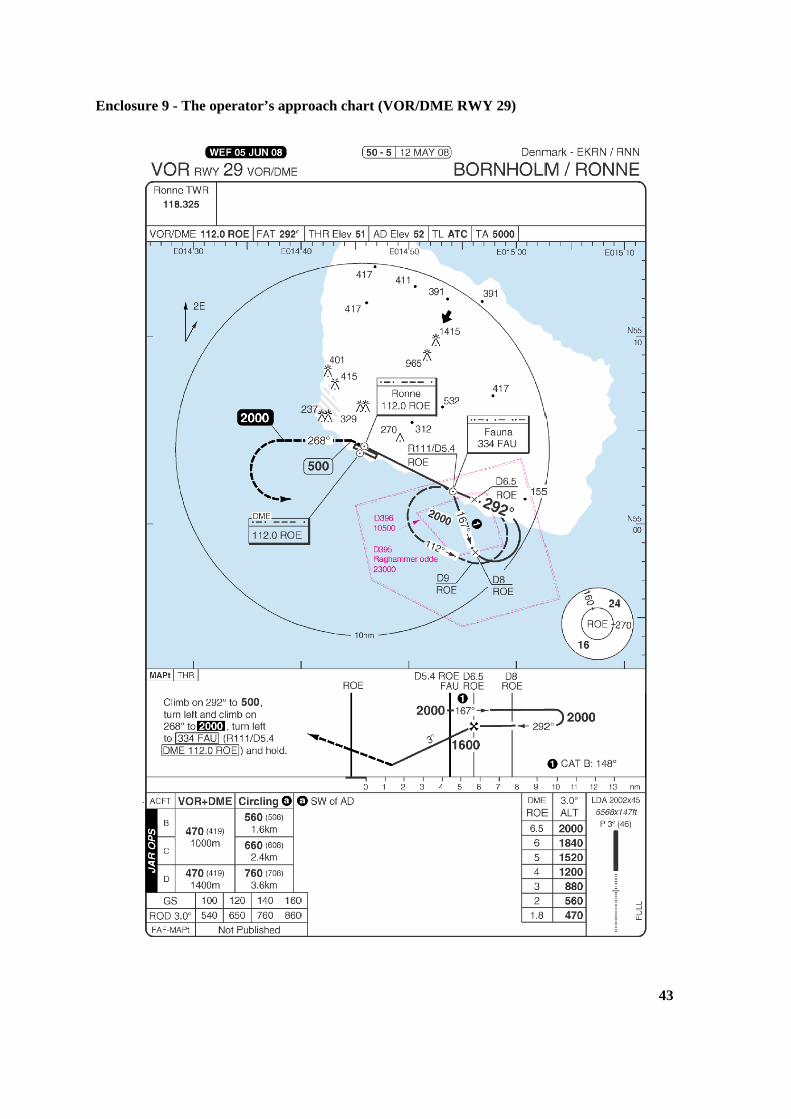
1.10.4 The operator’s approach chart (VOR/DME approach to runway 29)
See enclosure 9.
1.10.5 Guidelines for the airport’s winter service (EKRN)
See enclosure 10.
1.11 Flight recorders
Data from the aircraft’s Digital Flight Data Recorder (DFDR) and Cockpit Voice Recorder was read
out. The data was of a good quality and was used in the investigation. Extract of DFDR data, see
enclosure 1 to enclosure 7.
18
DFDR time is given in the enclosures. On the basis of the ATC voice communication, the AIB has
corrected the times indicated from DFDR time to ATC time. The DFDR touch-down time was
18:03:17. The ATC-corrected touch-down time was 18:07:18.
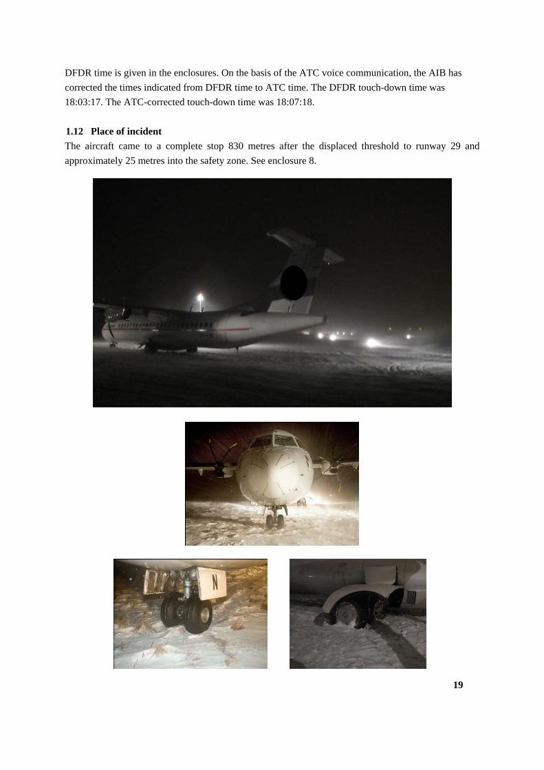
1.12 Place of incident
The aircraft came to a complete stop 830 metres after the displaced threshold to runway 29 and
approximately 25 metres into the safety zone. See enclosure 8.
19
1.13 Medical and pathological information
Not relevant.
1.14 Fire
There was no fire.
1.15 Survival aspects
There were no injuries to persons.
1.16 Tests and research
The AIB has not used any special investigative methods.
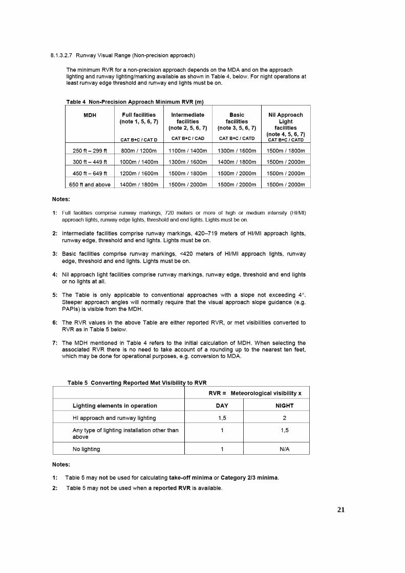
1.17 Organisational and management information
1.17.1 The Operator’s Operations Manual Part A (extract)
20
21
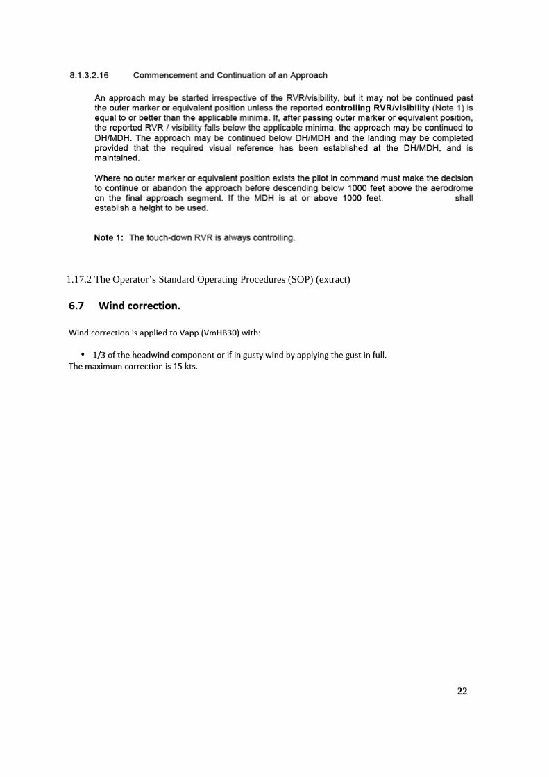
1.17.2 The Operator’s Standard Operating Procedures (SOP) (extract)
22
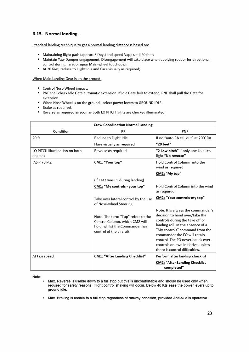
23
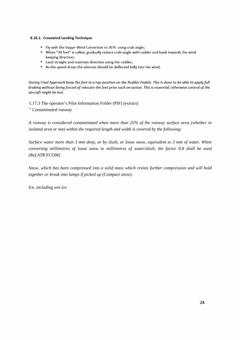
1.17.3 The operator’s Pilot Information Folder (PIF) (extract)
” Contaminated runway
A runway is considered contaminated when more than 25% of the runway surface area (whether in
isolated area or not) within the required length and width is covered by the following:
Surface water more than 3 mm deep, or by slush, or loose snow, equivalent to 3 mm of water. When
converting millimetres of loose snow to millimetres of water/slush, the factor 0.8 shall be used
(Ref.ATR FCOM)
Snow, which has been compressed into a solid mass which resists further compression and will hold
together or break into lumps if picked up (Compact snow).
Ice, including wet ice.
24
25
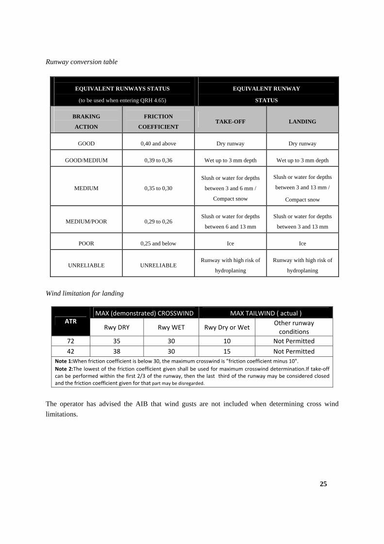
Runway conversion table
EQUIVALENT RUNWAYS STATUS
(to be used when entering QRH 4.65)
EQUIVALENT RUNWAY
STATUS
BRAKING
ACTION
FRICTION
COEFFICIENT
TAKE-OFF
LANDING
GOOD
0,40 and above
Dry runway
Dry runway
GOOD/MEDIUM
0,39 to 0,36
Wet up to 3 mm depth
Wet up to 3 mm depth
MEDIUM
0,35 to 0,30
Slush or water for depths
between 3 and 6 mm /
Compact snow
Slush or water for depths
between 3 and 13 mm /
Compact snow
MEDIUM/POOR
0,29 to 0,26
Slush or water for depths
between 6 and 13 mm
Slush or water for depths
between 3 and 13 mm
POOR
0,25 and below
Ice
Ice
UNRELIABLE
UNRELIABLE
Runway with high risk of
hydroplaning
Runway with high risk of
hydroplaning
Wind limitation for landing
MAX (demonstrated) CROSSWIND MAX TAILWIND ( actual ) ATR
Rwy DRY Rwy WET Rwy Dry or Wet Other runway conditions
72 35 30 10 Not Permitted
42 38 30 15 Not Permitted
Note 1:When friction coefficient is below 30, the maximum crosswind is ”friction coefficient minus 10".
Note 2:The lowest of the friction coefficient given shall be used for maximum crosswind determination.If take‐off can be performed within the first 2/3 of the runway, then the last third of the runway may be considered closed and the friction coefficient given for that part may be disregarded.
The operator has advised the AIB that wind gusts are not included when determining cross wind
limitations.
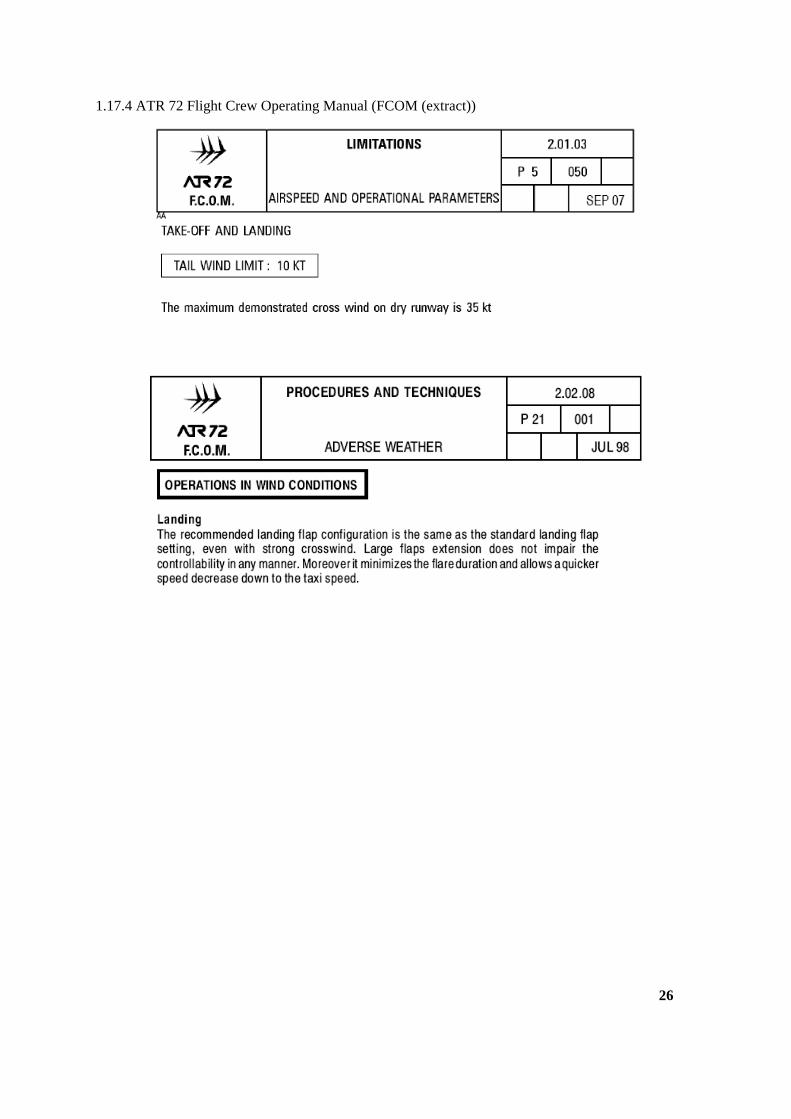
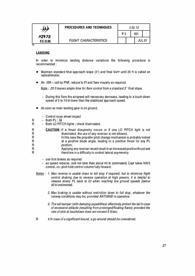
1.17.4 ATR 72 Flight Crew Operating Manual (FCOM (extract))
26
27
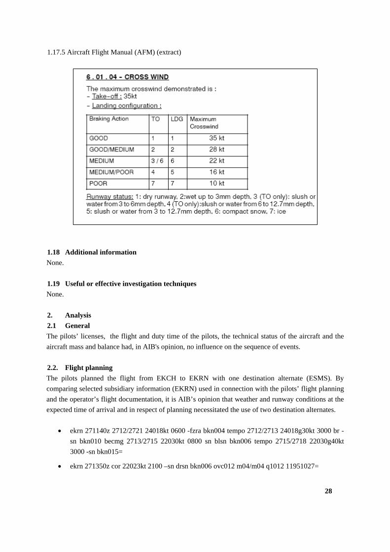
1.17.5 Aircraft Flight Manual (AFM) (extract)
1.18 Additional information
None.
1.19 Useful or effective investigation techniques
None.
2. Analysis
2.1 General
The pilots’ licenses, the flight and duty time of the pilots, the technical status of the aircraft and the
aircraft mass and balance had, in AIB's opinion, no influence on the sequence of events.
2.2. Flight planning
The pilots planned the flight from EKCH to EKRN with one destination alternate (ESMS). By
comparing selected subsidiary information (EKRN) used in connection with the pilots’ flight planning
and the operator’s flight documentation, it is AIB’s opinion that weather and runway conditions at the
expected time of arrival and in respect of planning necessitated the use of two destination alternates.
ekrn 271140z 2712/2721 24018kt 0600 -fzra bkn004 tempo 2712/2713 24018g30kt 3000 br -
sn bkn010 becmg 2713/2715 22030kt 0800 sn blsn bkn006 tempo 2715/2718 22030g40kt
3000 -sn bkn015=
ekrn 271350z cor 22023kt 2100 –sn drsn bkn006 ovc012 m04/m04 q1012 11951027=
28
29
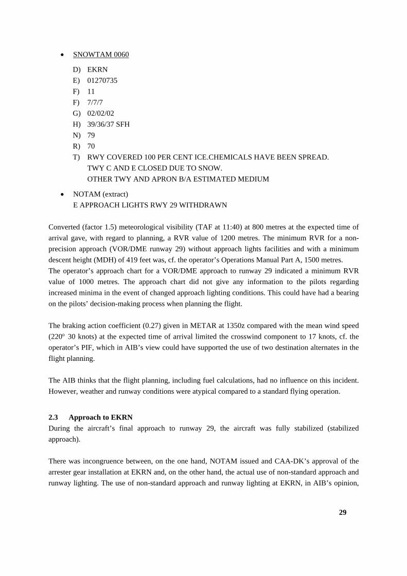
SNOWTAM 0060
D) EKRN
E) 01270735
F) 11
F) 7/7/7
G) 02/02/02
H) 39/36/37 SFH
N) 79
R) 70
T) RWY COVERED 100 PER CENT ICE.CHEMICALS HAVE BEEN SPREAD.
TWY C AND E CLOSED DUE TO SNOW.
OTHER TWY AND APRON B/A ESTIMATED MEDIUM
NOTAM (extract)
E APPROACH LIGHTS RWY 29 WITHDRAWN
Converted (factor 1.5) meteorological visibility (TAF at 11:40) at 800 metres at the expected time of
arrival gave, with regard to planning, a RVR value of 1200 metres. The minimum RVR for a non-
precision approach (VOR/DME runway 29) without approach lights facilities and with a minimum
descent height (MDH) of 419 feet was, cf. the operator’s Operations Manual Part A, 1500 metres.
The operator’s approach chart for a VOR/DME approach to runway 29 indicated a minimum RVR
value of 1000 metres. The approach chart did not give any information to the pilots regarding
increased minima in the event of changed approach lighting conditions. This could have had a bearing
on the pilots’ decision-making process when planning the flight.
The braking action coefficient (0.27) given in METAR at 1350z compared with the mean wind speed
(220 30 knots) at the expected time of arrival limited the crosswind component to 17 knots, cf. the
operator’s PIF, which in AIB’s view could have supported the use of two destination alternates in the
flight planning.
The AIB thinks that the flight planning, including fuel calculations, had no influence on this incident.
However, weather and runway conditions were atypical compared to a standard flying operation.
2.3 Approach to EKRN
During the aircraft’s final approach to runway 29, the aircraft was fully stabilized (stabilized
approach).
There was incongruence between, on the one hand, NOTAM issued and CAA-DK’s approval of the
arrester gear installation at EKRN and, on the other hand, the actual use of non-standard approach and
runway lighting. The use of non-standard approach and runway lighting at EKRN, in AIB’s opinion,
30
supported the pilots’ decision to use a runway visual range for a VOR/DME approach to runway 29 of
1000 metres as shown in the operator’s approach chart.
The pilots subsequently reported to the control tower that the aircraft had a crosswind limitation of 30
knots maximum. Viewed in relation to the reported runway conditions (The braking action coefficients
on runway 29 were, at approximately 17:02, measured to be 48, 51 and 53. 50% of runway 29 was
covered by two mm of dry snow), the crosswind limitation of 30 knots given by the pilots was more
restrictive than that indicated in the operator's flight documentation (35 knots).
The operator’s flight documentation stated that wind gusts should not be included when determining
crosswind limitations. During the second final approach to runway 29, the ATC reported crosswind
component (210 30 knots maximum 35 knots) was within the crosswind limitation of 30 knots
reported by the pilots. The theoretical calculations for instanteneous crosswinds applying to the final
approach showed that crosswind conditions were marginal (from 99 feet RA to 27 feet RA – an
average of 33 knots) but the crosswind components were within the aircraft's certified limitation of 35
knots.
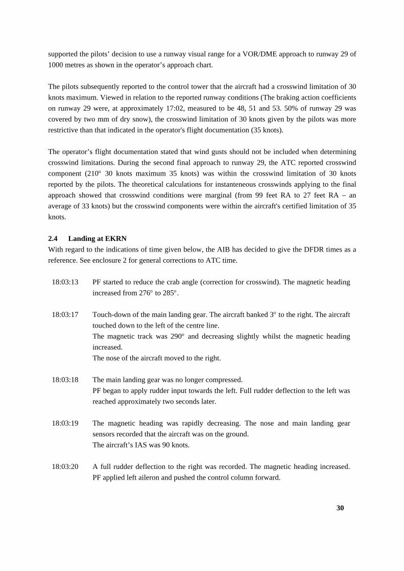
2.4 Landing at EKRN
With regard to the indications of time given below, the AIB has decided to give the DFDR times as a
reference. See enclosure 2 for general corrections to ATC time.
18:03:13 PF started to reduce the crab angle (correction for crosswind). The magnetic heading
increased from 276 to 285.
18:03:17 Touch-down of the main landing gear. The aircraft banked 3 to the right. The aircraft
touched down to the left of the centre line.
The magnetic track was 290 and decreasing slightly whilst the magnetic heading
increased.
The nose of the aircraft moved to the right.
18:03:18 The main landing gear was no longer compressed.
PF began to apply rudder input towards the left. Full rudder deflection to the left was
reached approximately two seconds later.
18:03:19 The magnetic heading was rapidly decreasing. The nose and main landing gear
sensors recorded that the aircraft was on the ground.
The aircraft’s IAS was 90 knots.
18:03:20 A full rudder deflection to the right was recorded. The magnetic heading increased.
PF applied left aileron and pushed the control column forward.

31
18:03:21 PF began to apply reverse on the engines. The magnetic heading continued to
increase.
18:03:24 A full rudder deflection to the left was recorded. The magnetic heading started to
decrease.
18:03:26-
18:03:30
The magnetic heading rapidly decreased from 295 to 275 with full rudder deflection
to the right. The aircraft’s IAS was below 50 knots.
18:03:30 PF applied brakes, full rudder deflection to the right and the control column (aileron
and elevator position) upwards towards the wind. The aircraft’s IAS was 30 knots.
The magnetic heading continued to decrease.
18:03:31 The aircraft ran over the side of the landing runway.
The attitude of the aircraft, the airspeed and the load factors were normal at the time of touch-down.
The landing technique at touch-down was in accordance with the operator and the manufacturer's
procedures. The pilots applied reverse on both engines after touchdown. No asymmetry of reverse
power was recorded
In AIB’s opinion, a combination of several conditions had influence on the sequence of events:
a) During the landing roll, the external visual references were limited because it was dark and
snow drifting. The snow drift from the south to the north may have led to an optical illusion that
the aircraft drifted to the north at first touch-down. In addition to the marginal crosswind
conditions leading to a significant increase in the magnetic heading , intensified by a 3 bank to
the right, an optical illusion may have led to the first full rudder deflection to the left during the
first touch-down.
b) The subsequent full rudder deflections during the landing roll might, in AIB’s opinion, be seen
as pilot reactions to the combination of lateral accelerations and heading augmentation during
marginal crosswind conditions.
c) The speed during the landing roll was decreasing gradually leading to a decrease of rudder
effectiveness which, in marginal crosswind conditions, made it all the more difficult for the
pilots to re-establish directional control.
d) As a result of the marginal crosswind conditions, during the last part of the landing roll, it is
likely that the aircraft was exposed to the weathercock effect, which intensified the aircraft's
trajectory over the side of the landing runway.
32
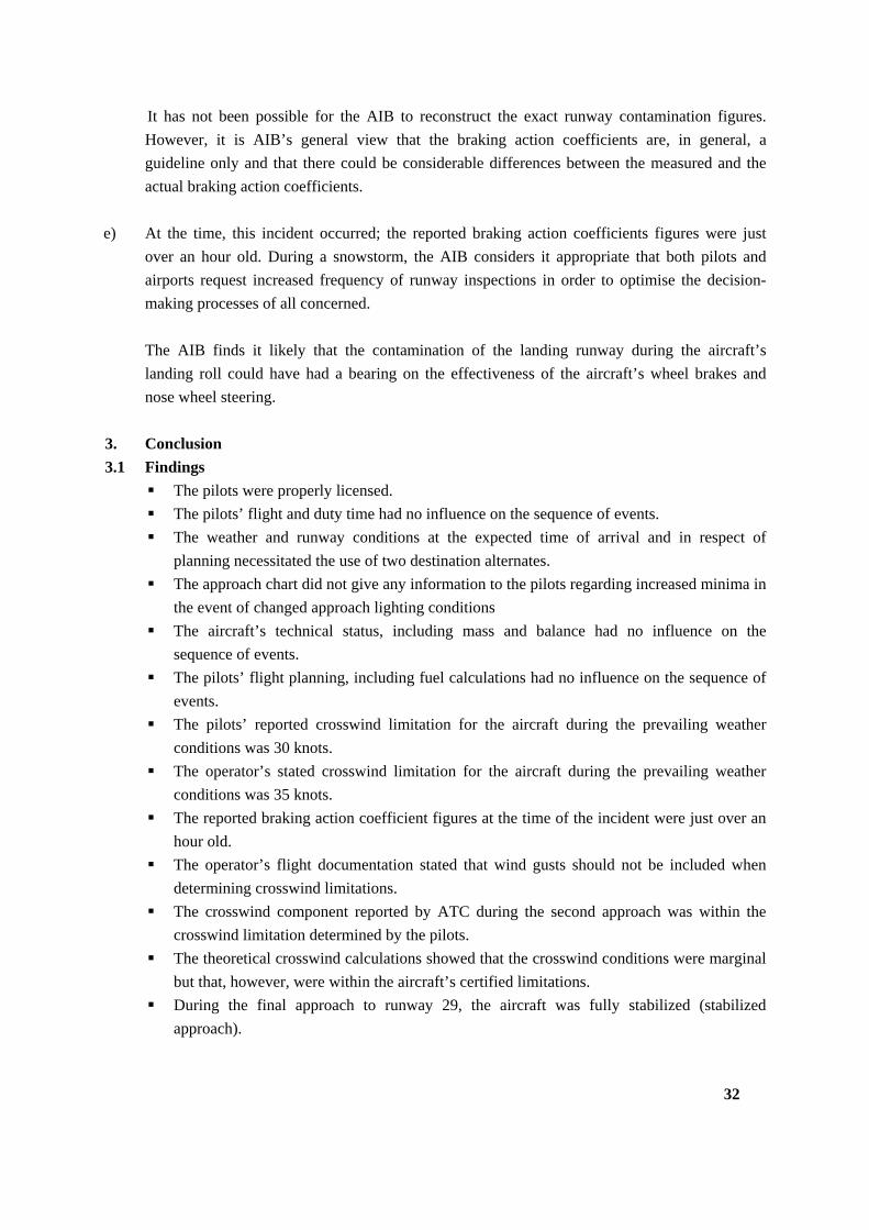
It has not been possible for the AIB to reconstruct the exact runway contamination figures.
However, it is AIB’s general view that the braking action coefficients are, in general, a
guideline only and that there could be considerable differences between the measured and the
actual braking action coefficients.
e) At the time, this incident occurred; the reported braking action coefficients figures were just
over an hour old. During a snowstorm, the AIB considers it appropriate that both pilots and
airports request increased frequency of runway inspections in order to optimise the decision-
making processes of all concerned.
The AIB finds it likely that the contamination of the landing runway during the aircraft’s
landing roll could have had a bearing on the effectiveness of the aircraft’s wheel brakes and
nose wheel steering.
3. Conclusion
3.1 Findings
The pilots were properly licensed.
The pilots’ flight and duty time had no influence on the sequence of events.
The weather and runway conditions at the expected time of arrival and in respect of
planning necessitated the use of two destination alternates.
The approach chart did not give any information to the pilots regarding increased minima in
the event of changed approach lighting conditions
The aircraft’s technical status, including mass and balance had no influence on the
sequence of events.
The pilots’ flight planning, including fuel calculations had no influence on the sequence of
events.
The pilots’ reported crosswind limitation for the aircraft during the prevailing weather
conditions was 30 knots.
The operator’s stated crosswind limitation for the aircraft during the prevailing weather
conditions was 35 knots.
The reported braking action coefficient figures at the time of the incident were just over an
hour old.
The operator’s flight documentation stated that wind gusts should not be included when
determining crosswind limitations.
The crosswind component reported by ATC during the second approach was within the
crosswind limitation determined by the pilots.
The theoretical crosswind calculations showed that the crosswind conditions were marginal
but that, however, were within the aircraft’s certified limitations.
During the final approach to runway 29, the aircraft was fully stabilized (stabilized
approach).
33
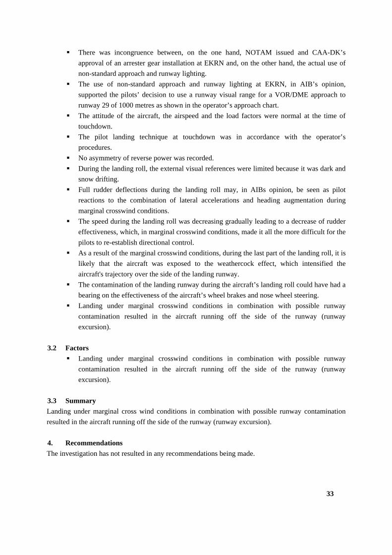
There was incongruence between, on the one hand, NOTAM issued and CAA-DK’s
approval of an arrester gear installation at EKRN and, on the other hand, the actual use of
non-standard approach and runway lighting.
The use of non-standard approach and runway lighting at EKRN, in AIB’s opinion,
supported the pilots’ decision to use a runway visual range for a VOR/DME approach to
runway 29 of 1000 metres as shown in the operator’s approach chart.
The attitude of the aircraft, the airspeed and the load factors were normal at the time of
touchdown.
The pilot landing technique at touchdown was in accordance with the operator’s
procedures.
No asymmetry of reverse power was recorded.
During the landing roll, the external visual references were limited because it was dark and
snow drifting.
Full rudder deflections during the landing roll may, in AIBs opinion, be seen as pilot
reactions to the combination of lateral accelerations and heading augmentation during
marginal crosswind conditions.
The speed during the landing roll was decreasing gradually leading to a decrease of rudder
effectiveness, which, in marginal crosswind conditions, made it all the more difficult for the
pilots to re-establish directional control.
As a result of the marginal crosswind conditions, during the last part of the landing roll, it is
likely that the aircraft was exposed to the weathercock effect, which intensified the
aircraft's trajectory over the side of the landing runway.
The contamination of the landing runway during the aircraft’s landing roll could have had a
bearing on the effectiveness of the aircraft’s wheel brakes and nose wheel steering.
Landing under marginal crosswind conditions in combination with possible runway
contamination resulted in the aircraft running off the side of the runway (runway
excursion).
3.2 Factors
Landing under marginal crosswind conditions in combination with possible runway
contamination resulted in the aircraft running off the side of the runway (runway
excursion).
3.3 Summary
Landing under marginal cross wind conditions in combination with possible runway contamination
resulted in the aircraft running off the side of the runway (runway excursion).
4. Recommendations
The investigation has not resulted in any recommendations being made.
34
5. Enclosures
1. Landing roll (overview picture)
2. Landing roll (DFDR/ATC time)
3. DFDR readout
4. DFDR readout
5. DFDR readout
6. DFDR readout
7. DFDR readout
8. EKRN overview picture (extract of AIP Denmark)
9. The operator’s approach chart (VOR/DME RWY 29)
10. EKRN’s Guidelines for winter service
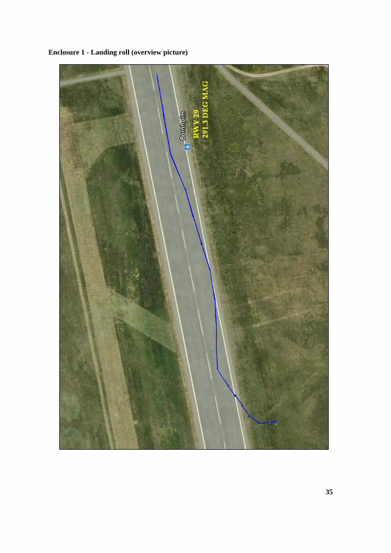
Enclosure 1 - Landing roll (overview picture)
35
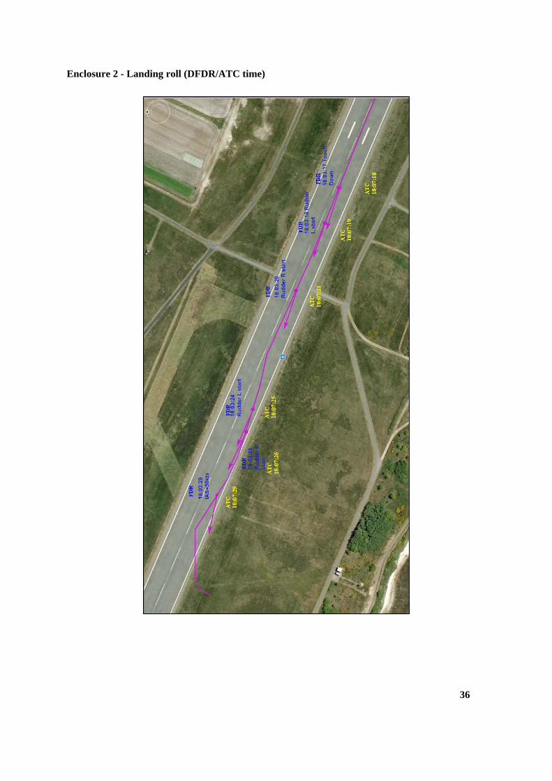
Enclosure 2 - Landing roll (DFDR/ATC time)
36
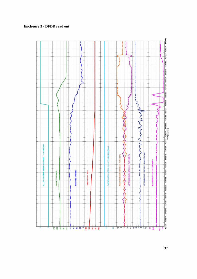
Enclosure 3 - DFDR read out
37
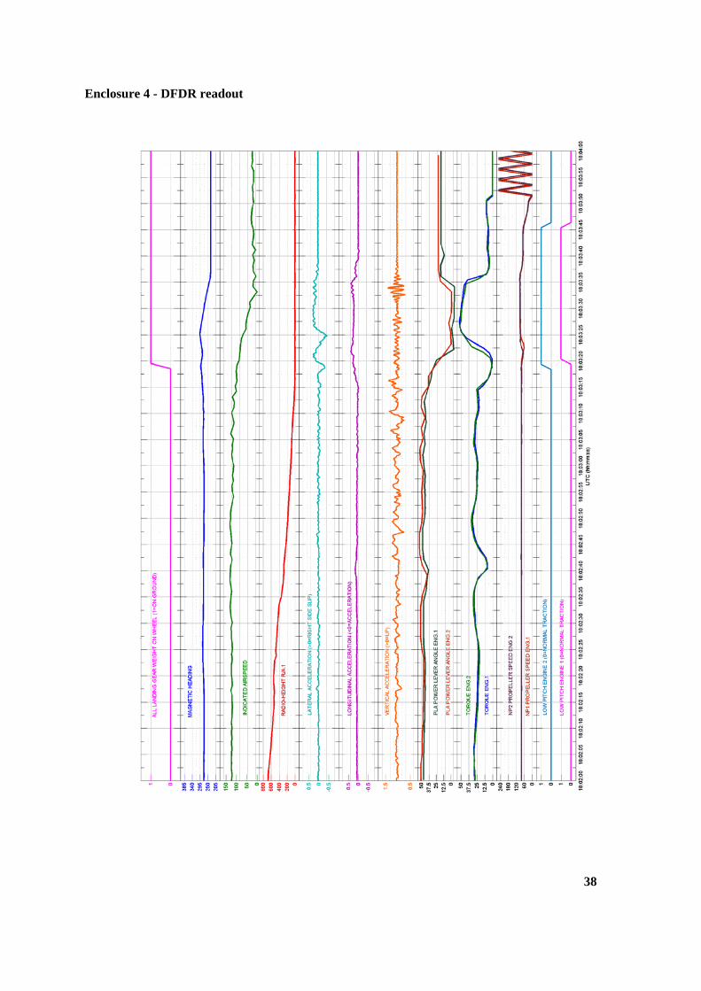
Enclosure 4 - DFDR readout
38
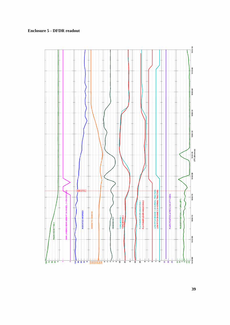
Enclosure 5 - DFDR readout
39
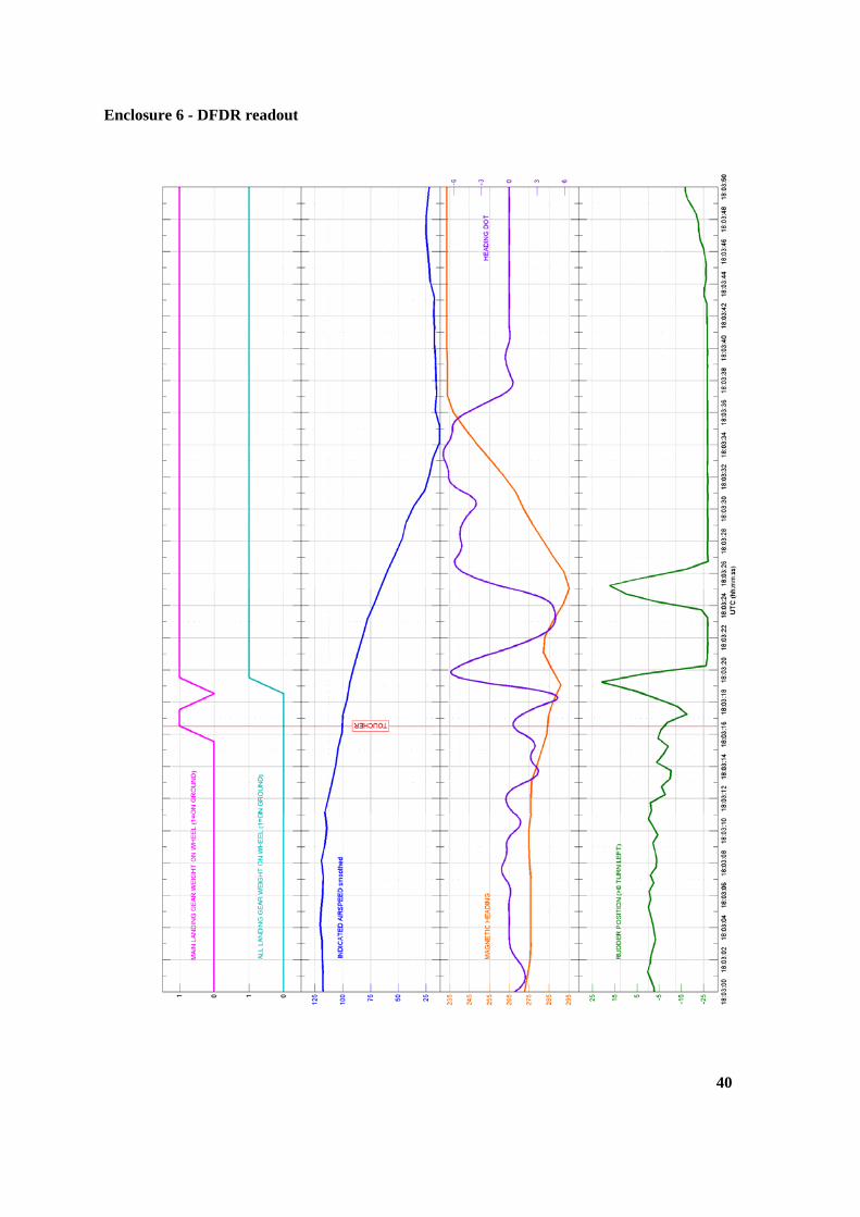
Enclosure 6 - DFDR readout
40
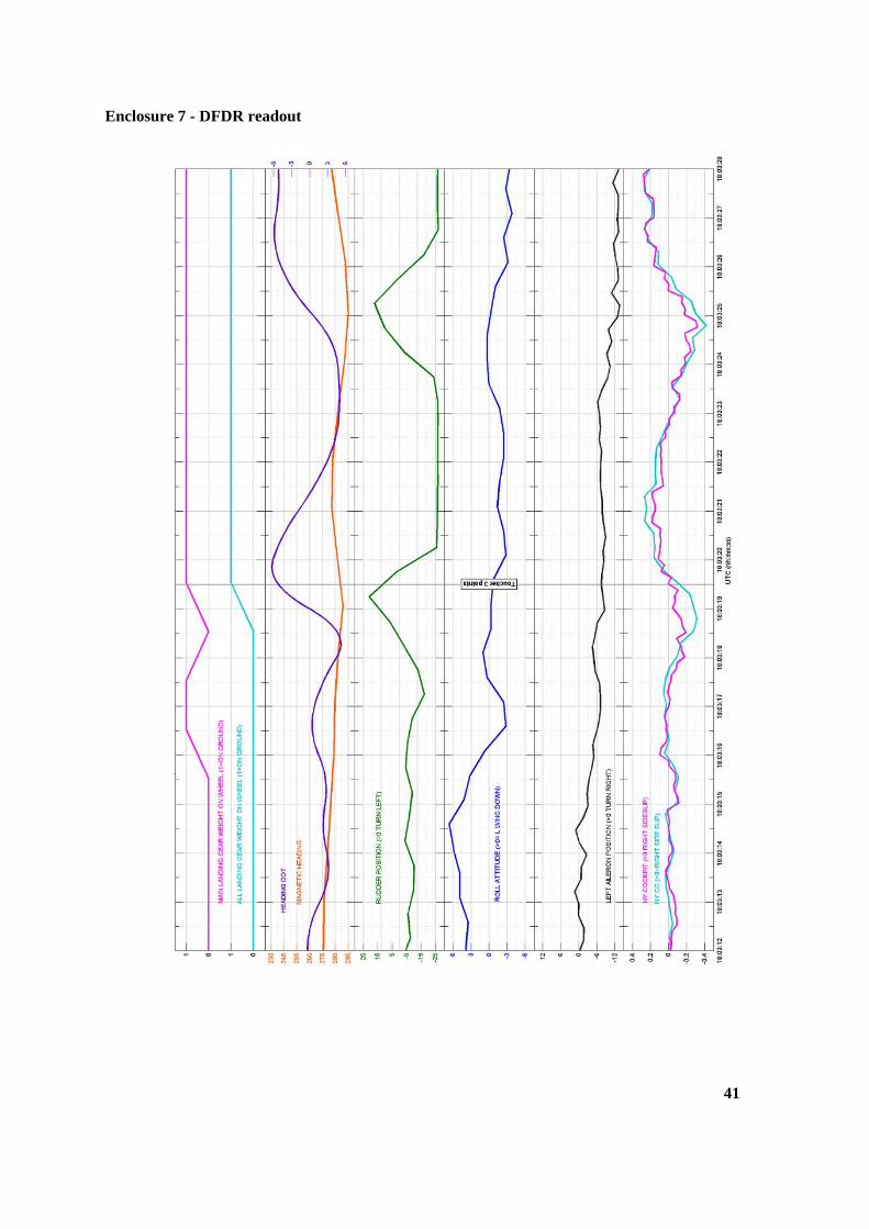
Enclosure 7 - DFDR readout
41
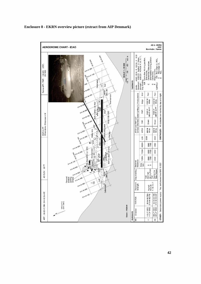
Enclosure 8 - EKRN overview picture (extract from AIP Denmark)
42
Enclosure 9 - The operator’s approach chart (VOR/DME RWY 29)
43
44
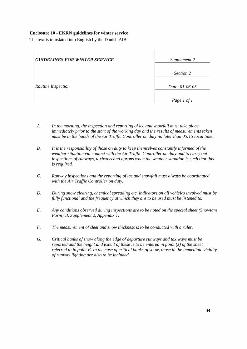
Enclosure 10 - EKRN guidelines for winter service
The text is translated into English by the Danish AIB
Supplement 2
Section 2
Date: 01-06-05
GUIDELINES FOR WINTER SERVICE
Routine Inspection
Page 1 of 1
A. In the morning, the inspection and reporting of ice and snowfall must take place
immediately prior to the start of the working day and the results of measurements taken must be in the hands of the Air Traffic Controller on duty no later than 05:15 local time.
B. It is the responsibility of those on duty to keep themselves constantly informed of the
weather situation via contact with the Air Traffic Controller on duty and to carry out inspections of runways, taxiways and aprons when the weather situation is such that this is required.
C. Runway inspections and the reporting of ice and snowfall must always be coordinated
with the Air Traffic Controller on duty.
D. During snow clearing, chemical spreading etc. indicators on all vehicles involved must be
fully functional and the frequency at which they are to be used must be listened to.
E. Any conditions observed during inspections are to be noted on the special sheet (Snowtam
Form) cf. Supplement 2, Appendix 1.
F. The measurement of sleet and snow thickness is to be conducted with a ruler.
G. Critical banks of snow along the edge of departure runways and taxiways must be
reported and the height and extent of these is to be entered in point (J) of the sheet referred to in point E. In the case of critical banks of snow, those in the immediate vicinity of runway lighting are also to be included.
45
H. Whenever there are ice, snow or slush, the estimated extent is to be indicated in Snowtam
point T, using the following values:
10%, less than 10% of the runway is covered
25%, 11-25% of the runway is covered
50%, 26-50% of the runway is covered
100%, more than 50% of the runway is covered.
I. A new “Snowtam Form” must be completed when any significant change to conditions in
relation to the most recently issued “Snowtam” are observed.
J. With regard to completing the “Snowtam Form”, refer to AIP Denmark AD 1.2-1 to AD
1.2-3.
K. The Air Traffic Controller on duty may request that a runway inspection be carried out
and ice and snowfall are reported if he/she considers - or the experience of pilots proves this necessary.


