Host Bureau of Reclamation Engineering and Research Center Denver, Colorado November 11-12, 1976 REPORT OF TENTH INTERAGENCY CONFERENCE ON HYDRAULIC LABORATORY TECHNIQUES AND INSTRUMENTATION
Transcript
Host Bureau of Reclamation
Engineering and Research Center
Denver, Colorado
November 11-12, 1976
REPORT OF TENTH INTERAGENCY CONFERENCE ON HYDRAULIC LABORATORY
TECHNIQUES AND INSTRUMENTATION
REPORT OF TENTH INTERAGENCY CONFERENCE ON HYDRAULIC LABORATORY TECHNIQUES
AND INSTRUMENTATION
Hosted by BUREAU OF RECLAMATION
ENGINEERING AND RESEARCH CENTER DENVER, COLORADO
NOVEMBER 11-12, 1976
TENTH INTERAGENCY CONFERENCE ON HYDRAULIC LABORATORY TECHNIQUES
AND INSTRUMENTATION NOVEMBER 11-12, 1976
S~RY
The meeting convened in the Division of General Research conference room at 8:15 a.m. on Thursday, November 11, 1976. Mr. Howard J. Cohan, Chief, Division of General Research, welcomed the group to the Engineering and Research Center of the Bureau of Reclamation. Mr. Dan King, Chief, Hydraulics Branch, the conference general chairman, opened the meeting with individual introductions and then explained the informal conference procedures. As in the past, the primary objective of the meeting was the providing of an opportunity for engineers and technicians to exchange ideas, experiences, and results of developing new techniques and instrumentation for hydraulic and fluid mechanics investigations in Federal laboratories.
A photograph of the people attending full and part time and list of names associated with each agency follows this summary. This meeting was the second attendance, in the series extending back to 1956, for representatives from the Geological Survey - Gulf Coast Hydroscience Center (USGS) and the Department of Agriculture Sedimentation Laboratory (USDA). The Naval Ship Research and Development Center (NSRDC) was not represented at this meeting.
The Thursday morning, November 11, session included presentations and discussions of (a) model control and data acquisition and (b) hydraulic laboratory techniques (see agenda in the following pages). Four of six items in (b) were completed between 1 and 2 p.m. The remaining 2 hours were used for a tour of the Bureau Hydraulics Laboratory and, for those who wished, visits were provided to the central processor of the Division Measurement Analysis and Control Computer System (MAC system) and to the Concrete and Structural Branch vibration laboratory.
On Friday, before the meeting was adjourned at 2:30 p.m. for individual discussions, information was exchanged on (c) measurement of velocity, (d) measurement of pressure, (e) measurement of water surface elevation, (f) field testing, and (g) miscellaneous.
The body of the report includes available descriptions of techniques, methods or instruments suggested for discussion. Discussions as recorded generally follow the previously submitted topic summaries.
CRITIQUE
Representatives from the various agencies had a lively interest in the suggested topics. Data acquisition from various types of studies appeared to be increasingly oriented to computer-assisted automation or supervisory control. Manipulation of minicomputer and microprocessor components to acquire data excited interest in the various agencies. New ideas were presented for the application and modification of established laboratory and field techniques in acquiring data from hydraulic investigations. Discussions among individuals continued through breaks and lunch periods indicating mutual benefit from the intormation exchange.
Without discussion, a biennial meeting period appears agreeable to the participants and the representatives from TVA were asked to arrange a 1978 conference with possible consideration for meeting at a laboratory of other than the three "parent" agencies.
2
•
w
..
~_.l~·-__
~ , Back Row (I eft to ri ght)
Hank Falvey, Vern Schneider, Frank Schiebe, Tom Rhone, Sam Powell, Alfred Nissila, Charles i..Jickles, Allen Tool, Gene Zeigler, Chris Ungate, Carl Pletcher, Dave Ehler, Doug Gober, Clark Buyalski
Front Row (left to right)
Phil Burgi, Bob Dexter, Bob George, Neil Coleman, Tom Isbester, Dinorah Esteva, John Shingler, Fred Hebran, Robert Havey, Jr., Don Warren, Jack Schuster, Mike Colgate, Perry Johnson, Russ Dodge, Dan King
Tenth Interagency Conference on Hydraulic Laboratory Techniques and Instrumentation - November 11-12, 1976
~
CONFERENCE PARTICIPANTS
Tennessee Valley Authority, Norris, Tennessee Chris Ungate Don Warren
Corps of Engineers
Office of the Chief of Engineers, Washington, D.C. Samual B. Powell
Chesapeake Bay Model, Virginia John Shingler
Waterways Experiment Station, Vicksburg, Mississippi Allen Tool Charles Nickles Fred Hebran
Coastal Engineering Research Center, Fort Belvoir, Virginia Dr. Dinorah Esteva Robert Havey, Jr.
North Pacific Division Hydraulic Laboratory Carl N. Pletcher Alfred G. Nissila
Geological Survey - Gulf Coast Hydroscience Center, Bay Saint Louis, Mississippi
Dr. Verne R. Schneider
Department of Agriculture Sedimentation Laboratory, Oxford, Mississippi Neil Coleman Dr. Frank Schiebe
Bureau of Reclamation, Division of General Research Howard J. Cohan Danny L. King Dr. Henry T. Falvey Thomas J. Rhone Jack C. Schuster Philip H. Burgi Donald Colgate Dr. Robert L. George David G. Ehler Douglas E. Gober Perry L. Johnson
4
"
Clark P. Buyalski Robert B. Dexter Russell A. Dodge Thomas J. Isbester Peter Julius Eugene R. Zeigler Philip F. Enger Edward A. Strickland James F. LaBounty
5
TENTH INTERAGENCY CONFERENCE ON
HYDRAULIC LABORATORY TECHNIQUES AND INSTRUMENTATION NOVEMBER 11-12, 1976
BUREAU OF RECLAMATION ENGINEERING AND RESEARCH CENTER
DENVER, COLORADO
Thursday, November 11
8:00
8:15 a.m.
8:30 a.m.
Chairman: Dr. Bob George Recorder: Mr. Dave Ehler
FINAL AGENDA
Registration
Welcome - Mr. Howard J. Cohan, Chief, Division of General Research
Introductions - Mr. Danny L. King, Chief, Hydraulics Branch Conference Chairman
Discussion of agency
A. MODEL CONTROL AND DATA ACQUISITION
6
1. Automated Data Acquisition and Control System - ADACS (WES)
2. Sensor-based Computer System -MAC (USBR)
3. Portable Model/computer Interface (USBR)
4.a. Applications for Minicomputers and Microprocessors (TVA)
b. Applications of Analog Devices Serdex Modules (WES)
c. (Not formally presented)(USBR)
5. Control of Wave Generators (CERC
6. Control of Density-stratified Reservoir Models (WES, USBR)
7. Digital Valve for Model Inflows (WES)
.,
10:15 a.m.
10:30 a.m.
Chairman: Mr. Phil Burgi Recorder: Mr . Doug Gober
11:30 a.m.
1:00 p.m.
Chairman: Mr. Phil Burgi Recorder: Mr. Doug Gober
2:00 p.m.
4:00 p.m.
Friday, November 12
8:00 a.m.
Chairman: Recorder:
Mr. Russ Dodge Mr. Perry Johnson
8. Set-point Flow-controller for Low-ambient-pressure Chamber (USBR)
Break
B. HYDRAULIC LABORATORY TECHNIQUES
1. Recent Experience in Thermal Modeling (TVA)
2. Production of Density Gradient in Shallow Flow (USBR)
Lunch (at Reuben's)
B. HYDRAULIC LABORATORY TECHNIQUES - contd
3. Simulation of Roughness (WES, USGS, USBR)
4. Highway-drainage Research Flume (USBR)
5. Low-ambient-pressure Chamber (USBR)
6. Survey of Current Techniques in Model Construction (TVA, WES, CERC, NPD, SPD, NSRDC, USDA, USGS, USBR)
Tour of Hydraulics Laboratory Host, Mr. Mike Colgate
Adjourn
C. MEASUREMENT OF VELOCITY
7
1. State of the Art of Laser Anemometry (USBR)
2. Propeller~, Cups, and Hot-film Anemometry (WES, TVA, USGS, USBR)
9:45 a.m.
10:00 a.m.
Chairman: Mr. Tom Isbester
11:15 a.m.
11:30 a.m.
12:30 p.m.
Chairman: Mr. Clark Buya1ski Recorder: Mr. Pete Julius
1:15 p.m.
Chairman: Mr. Bob Dexter Recorder: Mr. Mike Colgate
3. Electromagnetic Velocity Probes (WES, USBR)
4. "C1ampitron" Acoustic Flowmeter (USGS, USBR)
Break
D. MEASUREMENT OF PRESSURE
1. Mu1tiport Scanning Devices (WES, USBR)
2. Application of Pressure Transducers (USBR)
3. Dynamic Calibration of Pressure Transducers (USBR)
4. Correlations for Rate of Energy Dissipation (USBR)
Group Photograph
Lunch
E,
F.
MEASUREMENT OF WATER SURFACE ELEVATION
1. Ultrasonic Ranging Device (WES)
2. Water-surface Probability Probe (USBR)
3. Float-driven Potentiometer (USBR)
4. Capacitance and Resistance Probes (WES, TVA, USBR)
FIELD TESTING
1. Instrumentation and Techniques for Erosion Control Evaluation (WES)
2. Accelerometer Techniques for Torsional Slip Measurements on Hydroturbines (TVA)
8
1:45 p.m.
Chairman: Dr. Hank Falvey Recorder: Mr. Phil Burgi
2:30 p.m.
4:00 p.m.
3. Need for Portable Inertial Shaker System (TVA)
G. MISCELLANEOUS
1. Laboratory Tests on Fine-mesh Screens (TVA)
2. Metrication (USBR)
3. Potential for a symposium on laboratory techniques and instrumentation to include private laboratories (USBR)
Individual discussions as desired
Adjourn
9
A. MODEL CONTROL AND DATA ACQUISITION
1. Automated Data Acquisition and Control System (WES)
Mr. Allen Tool distributed copies of ARO Report No. 76-3 from the Proceedings of the 1976 Army Numerical Analysis and Computers Conference. He mentioned that the author, D. L. Durham, could not attend the meeting, but would be glad to answer questions by phone or letter. Also mentioned was that the system used an EAI Pacer 100 minicomputer. The abstract of Dr. Durham's paper is included below as part of this report.
AUTOMATED CONTROL, DATA ACQUISITION, AND ANALYSES FOR HYDRAULIC MODELS OF TIDAL INLETS
D. L. Durham, Wave Dynamics Division, Hydraulics Laboratory U.S. Army Engineer Waterways Experiment Station
Abstract, An Automated Data Acquisition and Control System (ADACS), developed (Durham and Greer, 1975) at the Waterways Experiment Station (WES) during the past 2 years, has been expanded to provide automated control, data acquisition, and analyses for hydraulic models of tidal inlets. ADACS configuration consists of a minicomputer with 32K l6-bit words of memory, an interval timer (1 ~ sec), an analog to digital l2-bit converter with 64 analog inputs (±10 volts) and 45-kHz multiplexer, 96-sense/control lines, a magnetic tape controller with two 9-track tape drives, a moving head disk controller with one dual disk drive (removable and nonremovable platters), one matrix electrostatic printer/plotter, and an ASR 33 teletype unit.
ADACS controls the hydraulic generation of the tide in the tidal inlet model by providing a programmable analog voltage to the hydraulic tide generator. The programmable tide controller can simulate a tide composed of one to N tidal constituents for as many tidal cycles as required. Model tidal elevations are recorded by ADACS u~ing a bubbler system which measures small hydrostatic pressure changes associated with changes in tidal elevations in the model. The bubbler system consists of a high-precision pressure transducer, and a "Scanivalve" for sequencing up to 48 pressure inputs. The pressure transducer can be calibrated prior to and at selected time intervals during each tidal test to provide accurate, updated calibration data for scaling voltage (pressure) data to tidal elevations. In addition to collecting tidal elevation data, tide velocities at specific model locations are monitored by using miniature, electromagnetic current meters. Besides controlling the tide generator during a tidal test, ADACS acquires the above
10
..
tidal data (elevations and velocities) including calibration information and test parameters and records these data on magnetic tape for future analyses and permanent storage.
Data analyses include scaling and editing of original data, least squares harmonic analyses of tidal data (elevation and velocity) for amplitude and phase of various tidal constituents, plots of original data and superimposed harmonic constituents, and analyses of residual variances. Verification of hydraulic tidal inlet models, which are geometrically distorted models scaled on the Froude model law, requires artificially simulating in the model the frictional effects associated with prototype roughness of bottom and sides of channels and overbank and marsh land roughness. The relative phase lags of major tidal constituents from one specific location to another in the prototype and the measurements of these phase lags in the model provide a means for estimating the amount of roughness and specific model areas requiring artificial roughness in order to achieve model verification.
2. Sensor-based Computer System (MAC System) (USBR) Strickland
The Instrumentation Group described the Bureau's system and invited the participants to see the facility. The system's initial cost was about $150,000 and we have added another $100,000 worth of equipment.
The Bureau's system is comprised of a Hewlett Packard (HP) central computer with six satellite computers. The central computer system includes:
1 - HP2108 computer with 96K of solid state memory 3 - HP7970A 1/2-inch, 9-track, 800-b/in magnetic tape units 2 - HP7900A moving head disks each with one fixed and one
removable disk with a capacity of 5 megabytes each disk I - HP7210A high-speed plotter I - HP2767A line printer I - High-speed paper tape photoreader 1 - High-speed paper tape punch 1 - Optical 300-character per minute card reader 1 - HP2600A CRT terminal 1 - Hazeltine 1200 CRT terminal 1 ASR-33 teletype system console 1 - Scientific Accessories Corp. Digitizer 1 - Telephone Modem
The central computer software is the Hewlet Packard RTE-3 with batch spool monitor with Fortran-4 compiler and assembler and with the HP distributed systems package. The software provides program entry, edit, development and storage capability, and loading capability for programs to be run in the satellite computers.
11
The satellite computers are HP2100's with 24K of memory each. The Bureau has six satellite (or remote) computers. Each computer is equipped with the following:
The satellite computers are hardwired to the central computer. The software package for the satellite computers is HP's BCS distributed software system. The remotes can also access all the central peripheral devices.
The six satellite minicomputers float through the division as branch computers and have sensor-based "front-ends." They are oriented toward gathering data (usually voltage signals) directly from transducers or test equipment and providing control. Signals are converted immediately into a digital number and entered into the computer. The computer then analyzes the data according to a Fortran program, and if necessary, provides control signals to open or close valves, turn motors off or on, etc. Each Branch computer "talks" to a central computer which has associated magnetic tapes, magnetic disks, paper tape punch, line printer, plotter, and other peripherals. Branch computers can use all of these devices.
3. Portable Model/Computer Interface (USBR) George
Before the power of a computer can be utilized in data acquisition, reduction, analysis, and presentation of these data must first be accessible to the machine. Data acquisition interface to a computer may be:
a. Data recorded and punched into card images
b. Analog recordings later digitized and put on machine compatible devices
c. Direct hardware connections between the transducers and the computer
12
The first method is error prone and requires considerable time to record the data and enter them into a computer if the amount of data is large. The other two methods require a hardware interface between the various types of transducers and the computer or analog recording equipment. When analog recording equipment is used, playback equipment, signal conditioners, filters, and digitizing equipment must be available to enter the data into the computer.
The third method above must be capable of interfacing input devices such as resistive bridges, voltage sources, current sources, frequency sources, capacitance devices, and LVDT's to a digitizer that usually has fixed voltage and impedance characteristics.
Methods to select from:
a. Buy separate amplifiers, signal conditioners, and hardwire each channel to computer
b. Build general purpose "black box" to amplify and condition signals and hardwire to computer
c. One or two with telecommunications
Items to consider about alternatives:
a. Cost
(1) Initial
(2) Maintenance
(3) Man-hours of training/user debugging faulty devices
b. Portability
c. Reliability
d. Ease of use. i.e .• convenient for end user. not electronic tech/repairman
e. Hookup time
f. Drift, stability, and linearity of system
Question: What are some pitfalls to avoid? . This general question was partially answered at various times during the discussion of the first four items in session A.
13
4.a. Applications of Microcomputers and Microprocessors (TVA)
Several microprocessor systems were discussed as in current use or being developed.
(1) The l20-channel data acquisition system is designed around the MITS Altair 8800 microcomputer (figure 1). The Altair 8800, based on the Intel 8080 microprocessor, is equipped with 16 bytes of random access memory, 8K bytes of read only memory, and a real-time clock card.
Data acquisition is by means of a l2-bit analog to digital converter and five 24-channel, solid-state multiplexers. Input to the multiplexers are Yellow Spring thermistors.
Input-output for the system is by means of an ASR 33 teletype as the control console and an RS-232 link to the Lab's main computer.
(2) A remote data acquisition system has been developed for use in monitoring the chimney liners of tall stacks (figure 2).
The system uses an Altair 8800B microcomputer with 32K bytes of memory and a dual-drive flexible disk system.
Primary sensors are 40 thermocouples which are read by a Doric Model 220 data acquisition system which provides a resolution of 0.1 0 F.
A unique feature of this system is that data collected are stored on disk and once a day the system automatically dials a GE Mark III time-share system and transfers the file to time-share system.
Information about the stresses in the stack liner is transferred to a remote CRT located in the control room of the plant.
(3) A rain and stream gage monitoring system known as Dial Interrogation Hydrologic Gaging System (DIHGS) has been under development for some time (figure 3).
The system makes use of the Bell System direct distance dialing to collect data from gages located over a five-state area. The central station uses a Nova 1200 computer and Vadic automatic dialing equipment while the remote gage uses a Motorola 6800 microprocessor.
ACCOUSTICAL A AUTO I-- RELAYS ~ COUPLER roc ANSWER AND- ANSWER " ~ TifiT SOLENOID
~~D FROM INTERNAL
MICROPHONE SYSTEM AMP PARAMETERS
1+15 1-15 DESK SET
DC/DC +12
TELEPHONE . ~
+5 CONVERTERS -5
12V
Figure 3 .. 01 HGS REMOTE STATION
SYSTEM VOLTAGES
The remote gage is normally powered down but is turned on when the phone rings. On powerup the gage executes a program stored in up to 4K of programmable read only memory. A scratch pad buffer of 512 bytes of random access memory is provided for message formatting.
The primary sensor is a synchrotransmitter mated to a rain or stream gage to provide a resolution of 0.01 inch of rain or 0.01 foot of elevation.
Connection to the telephone is by an acoustical coupler at the remote sites because of problems with data coupler failures on small rural telephone systems.
4.b. Application of Analog Devices Serdex Modules (WES) Shingler
WES is utilizing the Analog Devices Serdex modules in instrumenting and control of the Chesapeake Bay Model. These modules utilize ASCII coded messages generated by a teletype or minimicrocomputer to control various functions. These modules consist of:
(1) STX 1003 serial transmitter which, when combined with a multiplexer and A-D converter, can read several analog quantities
(2) SRX 1005 serial receiver which, when combined with a D-A converter, can provide an analog output together with several control signals
(3) SMC 1007/SMX 1004 serial multiplexer which provides multiplex capability in using the above modules
(4) SCL 1006 clock module for use with complex systems
A typical remote for the Chesapeake Bay Model includes one receiver (SRXl005), two transmitters (STXl003), one clock, A to D converters as required, and one BCD display. The central computer system consists of a TI960 minicomputer ($1,260), a model 733 teletype, and two 'Sykes cassettes ($6,250 each). Control of the model is accomplished using a Moore meter (fluidics oscillator type for high flows), a bearingless turbine flowmeter (for low flows), and digital valves.
4.c. (Not formally presented) (USBR)
The Bureau of Reclamation is working in the area of using microprocessor systems in the control of canal checks on the Bureau's irrigation canal projects. The system will use microprocessors at the canal checks to gather system information (water level, gate
18
position, etc.) and provide gate control. The control algorithm may be part of the microprocessor software or the microprocessor may be provided with a communications channel with the algorithm processed at a central computer. System monitoring, alarms, logging, and supervisory control are other considerations. The project is in early stages of development. Experience on similar projects is desired.
5. Control of Wave Generators (CERC) Esteva
Summary of the work being done at CERC by the Corps is included below.
Introduction
Much of the guidance available to the engineer faced with the task of designing coastal structures has been based on tests performed under idealized wave conditions. For in the past most hydraulic laboratory experiments, tests, and model studies of response to waves have been performed with monochromatic waves; that is, regular waves that resulted from sinusoidal motion of a bulkhead.
Three of the wave tanks at the new facilities recently built for the U.S. Army Coastal Engineering Research Center (CERC) at Fort. Belvoir, Virginia, are equipped with programmable wave generators, consisting of a piston, driven by a hydraulic servosystem. These generators, besides being responsive to signals from an electronic function generator, may also be driven by analog signals on magnetic tape or from a digital computer. Because of the magnetic tape and computer capabilities, it is feasible to use a control signal that will give rise to irregular waves in the tank.
Existing Approaches
Three major approaches have been used in laboratories around the world.
(1) Replication of theoretically derived spectra
(2) Generation of a gaussian distribution of water elevations
(3) Use of modified field wave records
a. Theoretically derived spectra may be approximated in the laboratory by generating electronic white noise and applying a suitable filter to obtain the desired shape. Another way is to combine sinusoids of appropriate amplitudes and frequencies derived using a theoretical spectrum and random phases. Disadvantages of this approach are:
19
(1) Most of the existing theoretical spectra have been based on a limited portion of the collected data.
(2) A given spectrum does not arise from a unique sequence of waves.
b. The second approach relies entirely on assumed statistics of water elevations. Indications are that these statistics are seldom satisfied for high sea states and in coastal waters.
c. Use of field records has the advantage that the statistics leading to the correct wave shape are built in. Application of a theoretically derived transfer function to the field record to obtain the required blade displacement is limited by the degree of applicability of the theory used in deriving the transfer function.
Planned Approaches
Two approaches are planned at CERC. One involves the use of individual sinusoids and combinations of sinusoids to generate the control signal.
In the first approach it is planned to get an empirical transfer function from a series of laboratory experiments each with a sinusoid of known period and amplitude. This transfer function will be used in simulating narrow-banded wave trains, proceeding to multiple trains, that is trains of different period, and ways of specifying spectral shape and achieving these will be investigated.
The second involves the use of scaled field wave records, that is, recorded prototype wave profiles, appropriately scaled to determine the required control signal to achieve a wave profile in the tank closely resembling the prototype profile.
In the approach involving field wave records, an iterative procedure will be used which will result in as close a replication of the observed field wave profile as possible in the tank.
The iterative procedure consists of the following:
Scale the field wave profile.
Use it as first approximation of time history of blade displacement.
Record resulting wave profile in the tank.
20
Obtain transfer function. - An approximation of the transfer function will be given by the ratio of the Fourier transforms of the measured wave profiles in the tank and the time history of blade displacements.
The inverse Fourier transform of the product. - Transfer function times Fourier transform of field wave record will provide the next approximation to the time history of blade displacement.
The procedure will be repeated until the closest approximation to the field wave profile is achieved.
Status
So far only the first technique has been actively pursued. An empirical determination of the transfer function is expected by the end of January or February. Work on the second approach is about to start using a field record chosen from wave records obtained in the field wave gage program at CERC.
Advantages
The expected advantages and results of this work are:
a. Irregular waves, having not only a spectrum resembling the observed spectrum but resembling in shape and sequence the observed prototype wave profile, will be generated.
b. Procedures and computer programs will be available to allow experiments under more realistic and physically possible wave conditions.
c. From the data collected and its analyses, improved analyses of laboratory wave data and more realistic laboratory tests of structures will result.
Summary
Two approaches for generating irregular waves are under development at CERC. These approaches aim at replicating observed field wave profiles empirically by generating the required digital control signal in a small computer which will convert it to an analog output to the blade.
The procedures developed will allow investigators to perform laboratory experiments under more realistic wave conditions. It is planned to generate a file of control signals on magnetic tapes to produce different spectral shapes.
21
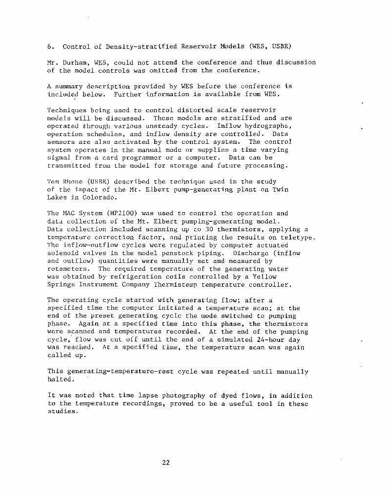
6. Control of Density-stratified Reservoir Models (WES, USBR)
Mr. Durham, WES, could not attend the conference and thus discussion of the model controls was omitted from the conference.
A summary description provided by WES before the conference is included below. Further information is available from WES.
Techniques being used to control distorted scale reservoir models will be discussed. These models are stratified and are operated through various unsteady cycles. Inflow hydrographs, operation schedules, and inflow density are controlled. Data sensors are also activated by the control system. The control system operates in the manual mode or supplies a time varying signal from a card programmer or a computer. Data can be transmitted from the model for storage and future processing.
Torn Rhone (USBR) described the technique used in the study of the impact of the Mt. Elbert pump-generating plant on Twin Lakes in Colorado.
The MAC System (HP2100) was used to control the operation and data collection of the Mt. Elbert pumping-generating model. Data collection included scanning up to 30 thermistors, applying a temperature correction factor, and printing the results on teletype. The inflow-outflow cycles were regulated by computer actuated solenoid vrtlves in the model penstock piping. Discharge (inflow and outflow) quantities were manually set and measured by rotameters. The required temperature of the generating water was obtained by refrigeration coils controlled by a Yellow Springs Instrument Company Thermistemp temperature controller.
The operating cycle started with generating flow; after a specified time the computer initiated a temperature scan; at the end of the preset generating cycle the mode switched to pumping phase. Again at a specified time into this phase, the thermistors were scanned and temperatures recorded. At the end of the pumping cycle,' flow was cut off until the end of a simulated 24-hour day was reached. At a specified time, the temperature scan was again called up.
This generating-temperature-rest cycle was repeated until manually halted.
It was noted that time lapse photography of dyed flows, in addition to the temperature recordings, proved to be a useful tool in these studies.
22
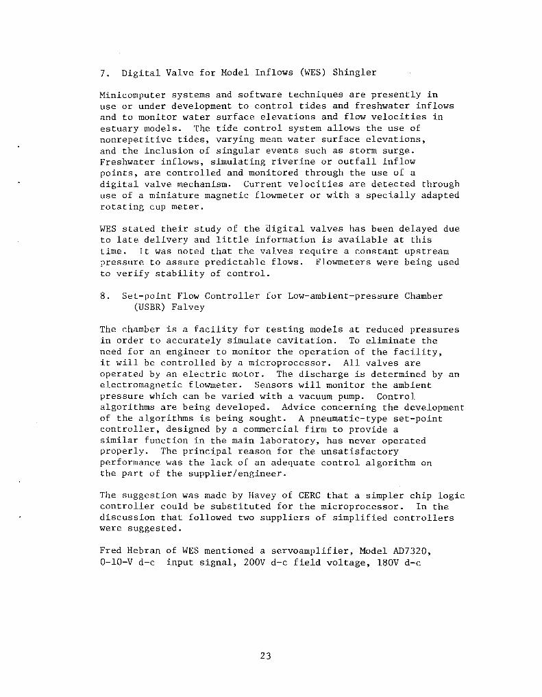
7. Digital Valve for Model Inflows eWES) Shingler
Minicomputer systems and software techniques are presently in use or under development to control tides and freshwater inflows and to monitor water surface elevations and flow velocities in estuary models. The tide control system allows the use of nonrepetitive tides, varying mean water surface elevations, and the inclusion of singular events such as storm surge. Freshwater inflows, simulating riverine or outfall inflow points, are controlled and monitored through the use of a digital valve mechanism. Current velocities are detected through use of a miniature magnetic flowmeter or with a specially adapted rotating cup meter.
WES stated their study of the aigital valves has been delayed due to late delivery and little information is available at this time. It was noted that the valves require a constant upstream pressure to assure predictable flows. Flowmeters were being used to verify stability of control.
S. Set-point Flow Controller for Low-ambient-pressure Chamber (USBR) Falvey
The chamber is a facility for testing models at reduced pressures in order to accurately simulate cavitation. To eliminate the need for an engineer to monitor the operation of the facility, it will be controlled by a microprocessor. All valves are operated by an electric motor. The discharge is determined by an electromagnetic flowmeter. Sensors will monitor the ambient pressure which can be varied with a vacuum pump. Control algorithms are being developed. Advice concerning the development of the algorithms is being sought. A pneumatic-type set-point controller, designed by a commercial firm to provide a similar function in the main laboratory, has never operated properly. The principal reason for the unsatisfactory performance was the lack of an adequate control algorithm on the part of the supplier/engineer.
The suggestion was made by Havey of CERC that a simpler chip logic controller could be substituted for the microprocessor. In the discussion that followed two suppliers of simplified controllers were suggested.
Fred Hebran of WES mentioned a servoamplifier, Model AD7320, O-lO-V d-c input signal, 200V d-c field voltage, lSOV d-c
23
armature voltage, available at Jordan Control, 5607 West Douglas Avenue, Milwaukee, Wisconsin 53218, (414) 461-9200. Ken McClendon, representative.
Charles Nickles of WES mentioned a null-balance inflow system, available at Moore Products, Baton Route, Louisiana, Wayne Gathwright, representative.
B. HYDRAULIC LABORATORY TECHNIQUES
1. Recent Experience in Thermal Modeling (TVA)
Model studies of discharges from submerged multipart diffusers in a rectangular open channel have been conducted in conjunction with design studies for the discharge system at TVA's Watts Bar Nuclear Plant. This system must dilute the discharge effluent by a factor of 10 for both a positively buoyant effluent and for a negatively buoyant effluent caused by operation of the natural draft cooling towers from the closed cycle plant. Negative buoyancy was modeled by means of heat utilizing a system of hot and cold water pipes with a mixing valve. Tests indicated that negative buoyancy tended to increase the dilution in jets with a positive vertical component of momentum due to the opposite direction of the buoyancy and inertial forces.
The equivalent slot concept for multipart diffusers in shallow water was tested in the model by varying discharge port diameters and port spacings. Tests of diffusers with the same equivalent slot but varying port configuration produced similar plume structure and dilutions.
Jet Reynolds number effects were investigated by comparing the tests of diffusers whose individual jet Reynolds number either violated or agreed with the current Reynolds number criterion for turbulent flow. Tests results tended to support a jet Reynolds number of around 1,500 as the criteria for turbulent flow. However, some tests indicated higher dilutions for jets with lower Reynolds number.
All test data were reduced such that plots of inverse dilution, rather than temperature excess, were prepared. Replicate runs of particular tests were also performed. These indicated that while plume structure was similar in each run, dilutions and plume areas exhibited considerable variation in most cases, thereby inqicating that quantitative data from thermal models of diffuser discharges must be interpreted with caution.
The time required for scanning the 85-90 temperature sensors in the model was noted as a probable cause for this variability. Fluctuations
24
in temperature caused by turbulent eddies probably occur at a faster rate than the temperature distributions can be scanned (1-2 sensors per second). A new scanner using a microcomputer has been proposed, which will scan the temperature sensors at the rate of 50 per second. This will allow a virtually instantaneous temperature distribution to be measured. Several of these "synoptic maps" can be measured in a period of minutes and averaged. This average temperature distribution should give a more accurate indication of plume characteristics in the thermal models.
2. Production of Density Gradients in a Shallow Liquid Flow Model of the Atmosphere (USBR)
A continuous pump mixing method was developed to produce complicated density profiles of developing storms in a stratified liquid atmospheric simulation model. Fresh and salt water from two tanks are mixed at the proper rates using a system consisting of valves and rotameters. Lighter density mixes are pumped into the model according to schedule and these layers are buoyantly lifted to the proper elevation by pumped-in denser layers. This procedure replaced a method utilizing molecular diffusion between two distinct density layers. The molecular diffusion method was abandoned because it required long waiting periods and could produce only lazy-S-shaped density profiles with little possibility of variance. Density profiles are determined by photographing a 45° angled rod in the medium and calculating density from the deflections of the image from a straight rod using principles of light refraction. The rotameters have been operated in suction using only one pump. A better approach would be to use two pumps and operate the rotameters on the discharge side of the pumps.
3. Artificial Simulation of Roughness (USBR, WES, USGS) Schneider (USGS)
The USGS has used a combination of astroturf and plastic box elder plants to simulate the flow pattern around a highway embankment and abutment in a heavily vegetated flood plain. Blocks and wire mesh were used in an earlier unsuccessful attempt at producing a Manning roughness coefficient of 0.30. The box elder plants were imported from Hong Kong. Total cost for 140 square metres (1,500 square feet) of the astroturf-box elder roughness was around $300 for materials.
The use of magnets is planned for attaching roughness elements in an energy dissipation study for a pipe outlet. The magnets will be easily moved to experiment with different configurations of
25
roughness elements. The magnets are available in various sizes and shapes with up to a 22S-N (SO-lb) pull.
(USBR) Burgi
Su~cessful simulating the roughness of a road surface on a long shallow flume provides flow conditions similar to those found on streets. The Manning roughness equation does not work for flow in this triangular cross section. For this reason, testing to evaluate the roughness was done at a flat cross slope to produce flow with a rectangular cross section. The first surface tested was No. 30 sand applied over wet epoxy paint. This treatment produced a Manning roughness coefficient of around 0.014. This surface was sprayed with marine varnish, coated with No. 8 sand, and then sprayed with one coat of marine varnish. The resulting roughness coefficient was 0.022. This surface was then sprayed with marine varnish, coated with No. 16 sand, and then sprayed with two coats of marine varnish. This surface produced the required roughness coefficient of 0.016 to 0.017.
4. Special Flume for Studies in Highway Drainage (USBR) Gober
The special flume and surface described above is being used for conducting hydraulic tests on draina_ge grates. The flume was designed to permit one-man operatioG and maximize testing efficiency. The longitudinal slope is ~dj'lstable from 0 ~c 13 percenc hy means of two 267 000 N (3-tOl-,) chain hoists simultaneously driven by a 378-w (1/2-horse?ower) gear r.-"J:::or. The water supply line is attached to the structure and is Taised and lowered with the flume. The water supply line on the flume is connected to a stationary line from the pumps by a dresser coupling mounted at the flume's pivot point. The coupling rotates as the slope is changed and has worked for over a year with no leakage. Flow rates are measured with a combination orifice-venturi meter that contains interchangeable orifice plates. The cross slope is adju$ted by a system of automobile-type screwjacks. The jacks are positioned along the length of the flume and are driven simultaneously by a drive shaft from a l86-W (1/4-horsepower) gear motor. The cross slope is adjustable from flat to as steep as 1:16.
S. Low Ambient Pressure Chamber (USBR) Falvey
USBR is constructing a 1.2 metre-wide and 4.6-metre long, low-ambient pressure chamber to simulate both Froude number and cavitation parameters simultaneously through reduced pressure.
26
The chamber will be capable of circulating about 0.3 m3/s through
open channel and closed conduit models under controllable conditions of partial vacuum. A set-point controller is planned for controlling discharge in the facility. Special tests have been conducted to insure good seals with silicone rubber at the Lexgard windows because other laboratories have experienced problems in this area. Bearings in the pump will be under water pressure to provide an airtight system.
6. Survey of Current Techniques in Model Construction (USBR) Rhone
The Hydraulics Branch no longer uses sheet-metal-lined boxes for their models. Permaply plastic-coated plywood is used almost exclusively and provides a waterproof box as long as the plastic finish is not damaged. Joints are lapped and sealed with either Dow Corning 781 building sealant or 3M weather stripping adhesive.
A successful fixed bed model has been constructed using topography formed of dense insulating styrofoam panels. The 19-mm (3/4-inch) thick sheets were cemented together, bolted to the model box, and can be readily shaped with carpentry hand tools. The foam's insulating properties should make it useful for thermally stratified reservoir models.
A recent thermally stratified reservoir model was built by shaping the reservoir in sand and fixing the surface with a sprayed-on epoxy coating. The coating is not watertight. The epoxy is quite toxic and is not recommended for indoor construction.
USBR has experienced problems with plexiglass absorbing water. On an atmospheric simulation facility, a 6-mm-thick, 4-m-diameter disk in contact with water on one side tends to "saucer" upward as the plastic absorbs water. No coating has been found which will seal the plexiglass without destroying its optic properties.
USDA reported that plexiglass apparently has a low coefficient of expansion also. A panel on a plexiglass-walled flume was shattered when the flume was filled with 1.7°C (35°F) water.
C. MEASUREMENT OF VELOCITY
1. State of the Art of Laser Anemometry (USBR) George
The increase in commercially available laser velocity meters as well as in available seminars, training sessions, and short courses in laser techniques was noted as evidence in applying laser
27
technology. USBR said that although it has interest in the device, neither the training nor the hardware have been actively sought. It was asked what other agencies experiences and thoughts on the subject were. One opinion was expressed that laser anemometers had little advantage over hot film probes. TVA indicated that NASA has some laser anemometers that they are not now using and which TVA has tried, to a limited extent, to obtain. TVA has not strongly pursued the acquisition and sees cost of the devices as a drawback. Dr. Schiebe expressed the opinion that laser anemometry is not required for our applications in velocity and turbulence measurements. Overall there was little enthusiasm expressed for this technique.
2. Miniature Propellers, Cups, and Hot-film Anemometry (USBR) WES, USGS)
Because of difficulty in obtaining foreign-made small propellers, the USBR Hydraulics Branch is planning to use hot-film sensors in the TSI anemometer system. In conjunction with the laboratory model of the magnetic current meter (Cushing), an attempt will be made to use anemometry for average and dynamic low-velocity measurements. Pilot tubes - Prandtl, cylindrical, and total head - will continue to be standards for velocities not measurable by the electrical methods.
The USGS has recently calibrated a NaVAR miniature current meter which appears to have a low-velocity cutoff of 10 to 20 mm/s, which is better than its advertised 1moJ' velocity of 25 mm/s (1 in/s). An automatic counter has been developed for use with the Price and pygmy current meter. It is not necessary to replace the contact wire with a magnetic head. USGS has been using both a single-channel and multiple-channel version in their flood plain research program.
With respect to propeller meters, most of the discussion dealt with the Armstrong-Whitworth miniature propeller meter now handled by Novonic-Nixon, Gloucester, England. Similar experience with the meter was expressed by several agencies including generally successful use but with fouling and shifting calibration problems. Fouling problems tend to be caused by fine fibers in the bearings that must be removed with the aid of a microscope.
WES then briefly mentioned that they have developed a photo-counter that can be used with cup meters. WES also .said that PNS Enterprise of Jackson, Mississippi supplies them with small cup meters with 19-mm (3/4-inch) diameter cups having comparable performance and threshold characteristics to Price meters that are considerably less expensive than the Price meters. Considerable interest was expressed in the PNS meter. WES was asked to supply information on the meter to the various agencies participating in the conference.
28
USGS then discussed two counters they have developed for use with Price and pygmy meters. One is a small, hand-held unit, that can be used with a single meter and a wading rod. The other is a larger multichannel unit that may be used at installations where many meters are used concurrently.
Finally, hot-film probes were discussed. USDA indicated they have had good luck using them to measure mean flow velocities. They have also found that calibrations do not drift over long periods of time and that the effect of dirty water on the life of the probe is minimal. It was warned that users of hot-film probes should take care not to use a too large overheat of the probes. Operational instructions are generally written for probe use in air and thus will result in overheating when the probe is used in water. This can cause heating and rising of the surrounding fluid which, in turn, may yield erroneous velocity measurements. The overheating can also reduce the life of the probe. It was noted that hot-film probes are nonlinear and that calibration for very low velocities is difficult.
It was also stated that armored probes appear to be quite good, but that because of their low frequency response, they cannot be used to study turbulence.
3. Electromagnetic Velocity Probes (USBR, WES)
USBR has obtained a laboratory-size model of the Cushing electromagnetic velocity probe. Two 9-mm (3/8-inch) diameter cylindrical probes are included, one with the sensing electrodes 9 mm (3/8-inch) from the bottom, the other 38 mm (1-1/2 inches) from the bottom. Full-scale deflection of the converter indicator can represent 0.3, 0.6, 1.5, or 6.1 m/s (1, 2, 5, or 20 ft/s). This is a factory modification to their standard converter. The original equipment time constants were also modified to comply with our specifications.
Initial use was in a movable bed model with shallow flow at velocities approximately 30 mm/s (0.1 ft/s) or less. To obtain velocities near the floor, the bottom of the probe was buried in the sand bed. To prevent fluctuating meter readings, it was necessary to operate on the internal battery rather than a.c. The device failed after about 100 hours' operation and had to be returned to the factory. After a few hours' use following its return, it became very inconsistent, necessitating further repairs which were done onsite by Mr. Cushing.
29
The meter was in storage for several months. When put back into operation, the calibration had changed and it was impossible to obtain a consistent recalibration. It was again returned to the factory for repair. At the present time, the meter is performing consistently and apparently is accurate.
Have other agencies experienced operating difficulties with this type of velocity meter?
Discussion on this subject primarily centered on comparison of experiences with the Cushing and the Marsh-McBirney probes. Both TVA and USBR stated that they found the Cushing meter to be poorly constructed and that they both had operation problems with the device. USDA indicated that they found the Cushing probe to be sensitive to d-c motor interference. They found that for laboratory use it was best to mount the probe on a plexiglass rod. USDA said that they satisfactorily used the Cushing meter in the field with batteries. They said that magnetite in the sand did not appear to affect the probe's operation. USGS said that Cushing had come to their laboratory to calibrate probes in a towing flume. He found that to obtain a clean, continuous signal, he had to insulate a source of electrolytic action in the flume from the water. In addition, he had to ground both the towing cart and the water.
WES, USGS, and USDA all indicated that they have had good experience with the Marsh-McBirney probe. USGS said that they have had a MarshMcBirney probe operating at a field installation for over a year without trouble. The probe receives only periodic checks. Dirt and slime on the probe do not seem to affect its performance.
Two other electromagnetic meter designs were briefly discussed. The first was developed at the University of Wisconsin. With it, the magnetic field is established externally to the flow. Thus, only small electrodes are required for the probes within the flow. The second design mentioned is for a small probe. The design was developed at Woods Hole and is discussed in a summer 1976 volume of the Journal of Limnology and Oceanography.
4. "Clampitron" Acoustic Flowmeter (USGS, USBR)
USGS has calibrated a Controlotron Corporation "Clampitron" flowmeter which is an ultrasonic meter designed to mount externally on a pipe to measure total discharge through the pipe. This portable meter has the potential for measuring pipe flow to within several percent depending on the degree of calibration.
30
"C1ampitron" recommends different transducers for use with different pipe materials and different pipe sizes. USGS has evaluated a single transducer on 150-mm (6-inch) pipe made of various materials. Schedules 40 and 80 steel pipe as well as PVC pipe were studied. It was found that the pipe material had only small effects on the meter's performance. USGS concluded that for the accuracy they require, use of a single transducer type is satisfactory. It was also found that output from the meter was linear, that warmup time was only a few minutes, that daily variations in rating are less than 2 percent, that the meter should be located a minimum of five diameters downstream from bends and irregularities, and that the meter should not be located near to upstream, abrupt expansions. The cost of the device tested is approximately $2,000.
USBR has also evaluated the "C1ampitron" flowmeter. USBR's tests were conducted on 76-mm (3-inch) steel pipe. The findings indicated that the meter was accurate within 3 percent of actual for all flows greater than 10 percent of full scale. For flows that were less than 10 percent of the meters full scale capacity, errors were somewhat greater. Detaching and replacing the transducers caused small additional error. The USGS and USBR exchanged data and information on the "C1ampitron" meter.
The Bureau is using multiport scanning devices for transmitting pressures from piezometers to a single-pressure transducer. The 48-port Scanivalve, a pressure transducer, and digital readout are mounted on a support containing a matrix-like panel for 48 pressure line connections. The Scaniva1ve ports were connected with tubing to one side of the panel and pressure lines from the test facility were connected as required to the opposite side. In the study, the transducer output voltage proportional to 1b/in2 was converted to head in feet with a digital readout to establish the pressure field of the water table from 48 piezometers in the vicinity of agri'cu1tura1 tube drains. An 18. 3-m (60-ft) long, 610 mm (24-in) wide, by 760-mm (30-in) high flume that could be sloped up to 12 percent was used for simulating drains in sloping land. This Scaniva1ve system has been used also for spillway crest pressure measurements and the measurement of head loss through a gravel drain envelope for essentially static heads.
In a second study, a motorized 48-port Scaniva1ve is being used with the MAC system with a remote terminal. The model is a 4.9-metre (16-foot) high full-scale test well constructed inside
31
the Hydraulics Branch Laboratory. Software is programmed to read pressures from a selected number of piezometers up to 48 and to read the output voltage of a magnetic flowmeter. Pressure and discharge data are recorded on magnetic tape for storage and computations.
Presently, at WES the Scanivalve pressure measuring system is replacing the use of water column manometers for the measurement of multiple pressures in pressure systems. The Scanivalve is a device that makes one integral pressure transducer do the work of up to 48. Multiple pressures are simultaneously applied to the 48 pressure ports of the Scanivalve. By individually stepping the Scanivalve ports to the pressure transducer, the pressure at that port is indicated by a digital voltmeter display. The pressure can be displayed as absolute or gage pressure.
The Scanivalve has increased the quantity and accuracy of sampling multiple pressures.
In addition to the premeeting report, WES reported on a threeScanivalve system for use in the New Melones Dam model. Pressure measurements are to be made in conduits upstream from Howell-Bunger valves. The entire system complete with Scanivalves, stepping mechanism, Druck pressure transducers, and hydraulic tubing connection boards was purchased from Scanivalve, and is shown in figure 4. Electrical lines from this equipment are connected to a control panel. With use of solenoid valves air bleeding is done from the control panel. Water and air in the hydraulic lines are purged near the pressure transducers. Operation of the Scanivalve system can be done from either a manual or computer mode. Presently, model operation is awaiting completion of the Howell-Bunger valves.
Premodel operation checks by WES show the equipment can scan 24 ports per second (each Scanivalve operating) while measuring static heads. Also, the equipment has been subjected to 517 kPa (75 Ib/in2) with no leakage at tubing connections and no pressure leaking between internal ports of the Scanivalves. Some hydraulic lines between pressure transducers and model are 15 m (50 ft) long and pressure measurements are for a slow frequency response. Other equipment is used for critical frequency pressure measurements in the model. In actual operation the first port of each Scanivalve will be connected to a 149-kPa (50-ft head) calibration pressure, and for each scanning cycle the computer will check this reading for accuracy. Cost of the equipment shown in figure 1 was stated to be approximately $10,000 and performance has been satisfactory. In the future it is planned to double the capacity from 144 to 288 ports.
32
Pressure lines
Figure 4
33
A linear-variable-differential-transformer pressure transducer manufactured by Robinson-Halpern was used in the USBR system because of good stability and accuracy. Water with minimum dissolved air was used in bleeding air from hydraulic lines leading to the Scanivalve. The hydraulic line attached to the pressure transducer was disconnected and water back-flushed through the Scanivalve. This prevented drawing sand particles and air bubbles through the Scanivalve. The system was used for pressure less than 15 kPa (S-ft head).
A Statham pressure transducer was used with the Scanivalve and rotary solenoid stepping mechanism. Instrumentation using the Scanivalve could be controlled manually by "pushbutton" or controlled by the HP-2l00 computer. Preliminary tests showed 0.8 second was a sufficient response time for a lSkPa (S-ft head) static pressure change.
2. Application of Pressure Transducers (USBR) Dexter
The Hydraulics Branch has used unbonded strain gage-type transducers with carrier-type preamplifiers for analog recordings for 0 to about 50-Hz pressure fluctuations. The present trend is toward d-c powered and d-c millivolt output transducers with signal conditioning circuitry built into the transducer case. We have had good results from Columbia Research Labs and Validyne transducers.
In addition to visual reading and manual recording of digital voltmeter (DVM) output signals from d-c type transducers, the signals are fed into two data acquisition and calculation systems. In one system, the signal is fed into DVM, converted to a BCD signal, then taken into storage in a Hewlett-Packard 9820 calculator for programmed calculations. A coupler controller in the system provides automatic scanning a maximum of 20 transducers. The second system, an HP 2100 minicomputer, receives millivolt output signals from transducers, through portable terminals, for data acquisition, calculation, and control of a Scanivalve.
We have recent information about sputter-deposited sensing material on a pressure transducer diaphragm that is sold by the CEC Division of Bell and Howell. They claim superior long-term stability, minimum zero shift, and exceptional linearity over a wide temperature range for the sputter-type transducer. However, the transducer case design prevents installation of a bleeding port that is necessary for measuring liquid pressures.
We are now considering acquisition of pressure transducers for dynamics up to about 500 Hz. Piezoelectric sensing elements seem to be most promising for dynamic pressure sensing.
34
Recently the USBR has purchased two Entran piezoelectric pressure tranducers. The pressure sensing diaphragm is exposed directly to fluid surface where the pressure measurement is to be made, with the intention of eliminating the proble~ of dynamic pressures traveling through rigid or semirigid tubing. Is a charge amplifier needed? Yes, to provide a low frequency response for the pressure transducer.
We do not have plans for a definite approach to obtaining good measurement of dynamic pressures in the frequency range 400-500 Hz while retaining capabilities for frequencies less than 100 Hz. One option is to use an oscilloscope for a display; the second, a fast paper speed direct writing recorder limited to approximately 100 Hz; and third, an analog to digital conversion for storage in a computer. The USBR has used an analog spectrum analyzer for dynamic analysis. What has been other people's experience in measuring dynamics? In answer, a suggestion was made to place the digital data in a computer and use a "Fast Fourier Transform" analysis.
In response to the question, "Has anyone used piezoelectric transducers?", some had used piezoelectric accelerometers. The general technique is to record the signal on a l4-track magnetic tape, then take the tape to the electronics laboratory, play back and analyze. A fast recorder speed is used for obtaining a good quality tape for a slower playback at the laboratory. Experience has shown the accelerometers limited to less than 500 Hz, but the other equipment can go higher in frequency. Is signal conditioning equipment needed to do this? The answer was yes.
3. Dynamic Calibration of Pressure Transducers (USBR) Isbester
Different in-shop methods of sine wave generators, step function generators, and an aperiodic shock tube have been tried for dynamic calibration of pressure transducers. Our latest effort was with a shock tube. Water was placed in a chamber and the chamber sealed on top with a thin glass diaphragm. Then air within the chamber was evacuated. The diaphragm was broken to instantaneously change pressure on the transducer. Different lead line materials, lengths and diameters, and various transducers were tested. The test program was time consuming and did not advance beyond the research stage. Lacking our own test facility, we have to trust the manufacturer's frequency response characteristics which are obtained using air as the fluid medium. Our transducer frequency response with water appeared to be approximately 100 times less in some cases than that reported by the manufacturer for air. Has anyone developed a good testing technique with water?
The USDA reported making the same type shock tube tests. They also had difficulties, but have not found anything better.
35
4. Correlations for Rate of Energy Dissipation (USBR) George
The turbulence characteristics of a flow approaching an energy dissipating structure are changed downstream by that structure. Rapid, high-amplitude velocity fluctuations are typical of flow downstream from a structure. This intense turbulent flow is gradually damped as the flow moves downstream and the excess energy is dissipated. At some distance downstream from the structure, a balance between the available energy and the frictional losses is reached. Beyond this point, no protection is required to prevent erosion to the downstream channel. The complex interactions between the boundaries, the geometry of the structure and the channel, and the flowing fluid make it difficult to determine the length requiring protection. Currently erosion tests on a model or prior experience is used to determine the required length.
The two following techniques can be used to evaluate the required length:
First, the length can be estimated by measuring the turbulence
intensity ~ at various distances from the structure and
Vx plotting this as a function of the distance. The turbulence intensity will be high near the structure, decrease rapidly as the distance from the structure increases, and reach a nearly constant value downstream. The distance downstream that
corresponds to a nearly constant value of /Vx,2 is the length requiring protection.
Vx
Second, the time history of the velocities at two points separated by a measured distance can be correlated. This correlation can be plotted as a function of the distance between the two points. When the distance is small, the correlation will'be very close to 1.0 and the correlation will decay rapidly as the distance increases. An estimate of the size of the eddies can be obtained from these correlations. This process can be repeated at successive cross sections downstream until a nearly constant eddy size is obtained. The section that results in nearly constant eddy size downstream from a satisfactory structure will determine the length needing protection.
36
Problem: What is the "best," most trouble-free method to obtain the velocity fluctuations? Pitot tube and transducer? Hot-film probe? Laser-Doppler anemometry? What about mean velocities? Frequency considerations, suitability of use in laboratory and field?
The reason for making the measurements is to determine where turbulence has returned to acceptable levels downstream from a stilling basin and to determine the extent of the riprap protection. We are interested in the experience of others in measuring turbulence downstream from structures.
If the waterflow reverses, then difficulties occur with hot-film and propeller-type velocity measurements. Also, entrained air confuses the hot-film measurements. There is a report by Resch, F. J., Leutheusser, H. J., and Alemu, S. "Bubbly Two Phase Flow in the Hydraulic Jump," Jour. Hyd. Div., ASCE, Vol. 100 HY 1, p. 137, 1974, using hot-film instrumentation for flow with entrained air to measure the void fraction and velocity fluctuations.
Another approach to the riprap problem downstream from a stilling basin has been reported by Tom Murphy of WES. His study included preforming a scour hole and, thus, obtaining some assurance of what can happen downstream from the basin.
Interpreting an overall effect from a series of point measurements is difficult in many cases. For example, efforts have been made to determine force loadings on stilling basin walls by pressure transducer measurements. Finally, a model was constructed with a hinged wall as a dynamometer for measuring overall wall forces caused by the pressure surges within the stilling basin. Similarly downstream model erosion is an indication for overall effect of stilling basin action.
The USGS used a Price current meter in a river and made velocity fluctuation measurements by counting every propeller revolution. Then hot-film instrumentation was used and showed good agreement for these field measurements.
Delft Laboratory reported use of a small plastic propeller with a perforated rim. Counting the light pulses passing through the perforations measured the rotary speed variation of the propeller. Results of a paper (1967 Twelfth Congress of IAHR, Fort Collins, Colorado) were inconclusive but the idea sounds good.
Another consideration is not to try measuring extremely small-scale turbulence. Large-scale turbulence, associated with large eddy size, occurs in a stilling basin. Probably an eddy size similar to riprap
diameter would indicate what order of turbulence size measurement to strive for. Dr. Schiebe mentioned he did his doctoral thesis on the subject of energy dissipation.
E. MEASUREMENT OF WATER SURFACE ELEVATION
1. Instrumentation for Measurement of Water Surfaces on Hydraulic Model Study Investigations (WES) Nickles
The Waterways Division is investigating a modified pulse modulated ultrasonic ranging device (model LD lOlA) to measure water surface elevations. Results of limited testing proved the LD lOlA was stable for the accuracy required over the temperature range specified. The LD lOlA compares a known distance to the variable distance to eliminate errors due to the change of velocity of sound caused by air temperature or changes in the electronics. The LD lOlA is composed of two units: (1) the head containing the transmitter, receiver, and control logic, and (2) the display unit containing power supply, microprocessor, and output modes. Part of the sonic cone is intercepted over a known distance and used by the microprocessor to calibrate the device for changes in the velocity of sound. The maximum voltage carried in the cable between the head and display unit is 24 V d.c •• The display unit is powered by 115 V a.c., 50-60 Hz, and consumes less than 100 watts of power. The LD lOlA is designed to measure any changing level that will give a suitable return signal. Some of these are liquids of all types, flat metal surfaces, smooth soils, et cetera. The unit can be used in four output modes: (1) visual display, (2) BCD output, (3) analog output, and (4) binary output. The head is a cylinder 128 mm (5 in) tall and 152 mm (6 in) in diameter with the two focusing horns 89 mm (3.5 in) long and a calibration rod 305 mm (12 in) long extending below the cylinder. The head must be. mounted so that the horns are perpendicular and not more than 1200 mm (3 ft) above the surface to be measured. The size of the area to be measured should be at least 50 mm (2 in) in diameter. The LD lOlA is designed to operate at an accuracy of +0.3 mm (+0.001 ft) per 300 mm of travel in a temperature range of DOC-to 49°C -(32°F to 120°F) at a maximum humidity of 100 percent and a storage temperature of -18°C to 60°C (O°F to 140°F). The LD lOlA was designed and manufactured by Diversified Technology, Inc., of Jackson, Mississippi.
Mr. Nickles, discussed the cost of the LD lOlA,. and noted the economic advantages of the device. Mr. Hebran wondered about possibly using such a device for movable sediment beds 0-1 m (0-3 ft) under water. It was stated that such a unit would cost about $15,000 but that a Boulder firm could supply a similar unit for $4,000. Neil Coleman of USDA described a device for measuring
38
shallow flows from 15 mm to 0.3 mm (0.05 ft to 0.001 ft). Mr. Schiebe also noted that his agency has purchased five ultrasonic sounders from Stevens International at $705 each for use as a stream gage. This was compared to the sonic gage that Mr. Nickles had acquired for $2,400. It was stated that the firm Automation Industries, Boulder, Colorado, makes underwater sounders and that Mr. Hebran of WES was interested in possibly acquiring one.
2. Water-surface Probability Probe (USBR) Falvey
A water-surface probability probe was constructed based on the St. Anthony Falls design, figure 5. The probe measures the probability that the water surface is equal to or greater than the indicated depth. Calibration is simple, and the readout does not require a conversion to obtain the answer. Mean depths can be determined objectively from two measurements and a plot on log-probability paper. When the probe was used on open channel flow with high velocities and shallow depths, the probe indicated lower values for the mean depth than a point gage indicating water contact by a buzzer. The acoustic probe requires the subjective estimate of an intermittent tone sounding 50 percent of the time.
3. Float-driven Potentiometer (USBR) Buyalski
An economical and accurate water level sensor using standard float-type pulley hardware has been used for canal automatic control systems. The water level sensor includes a standard float pulley assembly for 10:12 and 5:12 gage scales used on a Type A35 Leupold and Stevens recorder mounted on a fabricated l6-gage aluminum support. A 10-turn wire-wound, hermatically sealed potentiometer is coupled to the gear standard (1:5) output shaft with 5-mm (3/l6-inch) i.d. flexible clear plastic tubing. A 300-m (12-in) float and 460-mm (IS-in) circumference pulley arrangement can react to water level changes in a stilling well with a sensitivity equal to a pressure transducer. However, the reversal of water level direction produces a larger flat spot in the potentiometer output than normal caused by the flexibility of the plastic tube coupling (a direct drive eliminates this problem). A float size as small as 125 mm (5 in) can be used but with some decreased sensitivity. A sheet metal hood is placed over the water level sensor assembly where dust, water, etc., types of conditions are encountered.
4. Capacitance and Resistance Probes (WES, TVA, USDA)
The question arose as to the effect of the gage shape on the wave measurement and the problems encountered in obtaining
ALL RESISTORS 1/2 W" AfS ARE DUAL A747 OP AMP IN t OU TARE DU.!t BANANA JACKS
high resolution for large variations in level. Of interest was the difference of operation of resistance level detectors in salt and fresh water. Mention was made by CERC of a point contact (nails) step gage using CMOS chips as being satisfactory.
F. FIELD TESTING
1. Instrumentation and Techniques for Erosion Control Evaluation (WES) Tool
Monitoring of Demonstration Sites for Streambank Erosion Control Evaluation
and Demonstration Act of 1974 ("Section 32 Program")
The Streambank Erosion Control Evaluation and Demonstration Act of 1974 (Section 32, PL 93-251) authorizes a national streambank erosion prevention and demonstration program. The program consists of (1) an evaluation of the extent of streambank erosion on navigable rivers and their tributaries; (2) development of new methods and techniques for bank protection, research on soil stability, and identification of the causes of erosion; (3) a report to the Congress on the results of such studies and the recommendations of the Secretary of the Army on means for the prevention and correction of streambank erosion; and (4) demonstration projects, including bank protection works.
Demonstration projects authorized by the Act shall be undertaken on streams selected to reflect a variety of geographical and environmental conditions, including streams with naturally occurring erosion problems and streams with erosion caused or increased by man-made structures or activities. At a minimum, demonstration projects shall be conducted at multiple sites on (1) the Ohio River; (2) that reach of the Missouri River between Fort Randall Dam, South Dakota, and Sioux City, Iowa; (3) that reach of the Missouri River in North Dakota at or below Garrison Dam; and (4) the delta and hill areas of the Yazoo River Basin.
Monitoring guidelines for the demonstration sites are important for uniform and adequate data collection and will include soils as well as hydraulics aspects. Suggested monitoring includes: local stages; wave heights, periods, and directions; wave rideup; mean and local velocities; pore pressures; river traffic data (type, amount, size, speed, wake waves, etc.); material properties; cross-sections; acoustic soundings of submerged surfaces; periodic onsite visual observations; still and motion pictures; sediment transport and bar activity; and soil mass stability.
41
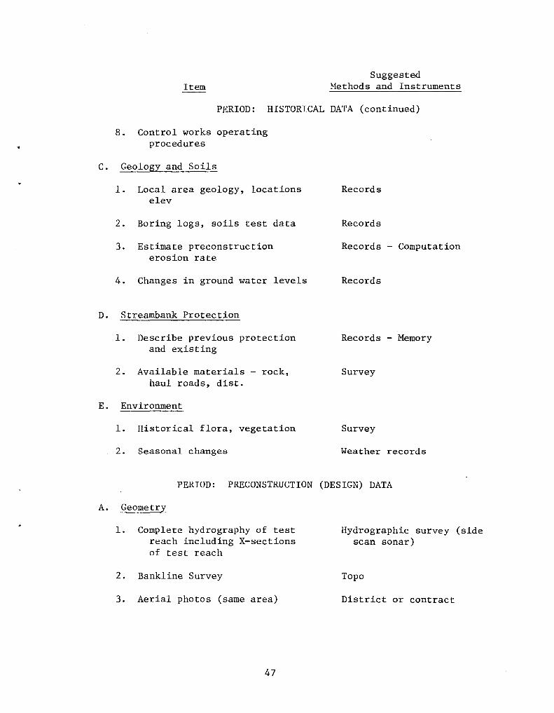
A topical outline of needed data for documentation of the demonstration projects was prepared. The types of data are subdivided to their "sequential" order: historical (as available), preconstruct ion (or design data), during construction, as constructed, and observation period (including end condition and reconstruction) and their "physical" characteristics: geometry, climate, hydrology and hydraulics, geology and soils, and streambank protection method (Appendix A).
Questions were asked regarding the USGS involvement in the study, the measurement of wave height as the stage changes, and the method of making wintertime measurements. Water stage measurements will be correlated with USGS during the test program wherever possible. Pressure cell measurements are unsatisfactory for wave height determinations over a large range of water stage - a stilling well should be used for water stage and a float gage for wave height. Visual observations will be made for ice during frigid weather.
A bank erosion study on the Willamette River in Oregon was discussed briefly.
2. Accelerometer Techniques for Torsional Slip Measurements on Hydroturbines (TVA)
Snapping or cracking noises during transient torque conditions on hydroturbine units lead to investigations of the cause of the noise. Pairs of accelerometers were mounted on the shafts and shaft coupling and two signals were simultaneously recorded on analog magnetic tape via Accurex (Model 1207), Mountain View, California, noncontacting telemetry. All signals were recorded on magnetic tape and included /' a microphone pickup to correlate sound with shaft movement. The phase relationship of the first excursion of pairs of accelerometer outputs and the frequency spectrum of the output pinpointed three sources of the noise: a vertical separation near the center of the shaft coupling (no separation at flange periphery), a torsional slippage at the shaft coupling, and a torsional slippage of the generator spider arms relative to the hub. Plans are underway for perlodic tests with fatigue-strain gages and accelerometers. Short records will be processed and the spectral contents of the records will be monitored with time to discover changes that may indicate a worsening of the slippage.
3. Need for Portable Inertial Shaker System
Information was requested regarding the availability of a portable shaker system. Two possible sources were suggested: University of California at Berkeley and Dr. Housner, California Institute of Technology.
42
G. MISCELLANEOUS
1. Laboratory Tests on Fine-mesh Screens
Fish entrainment and impingement of larval fish at nuclear plant intakes are becoming an increased concern to the Nuclear Regulatory Commission and to the Environmental Protection Agency. TVA has undertaken a series of studies to evaluate various types of screening materials to mitigate entrainment and impingement. These studies are a cooperative effort of the Engineering Laboratory personnel and biologists from the Division of Forestry, Fisheries and Wildlife Development.
Physical tests of the impingement and entrainment of larval fish have been conducted in the laboratory for fine mesh screens ranging from opening sizes of 1/2 mm to 1.2 mm. Johnson Well screens which have a spiral slot have been tested with slot widths ranging from 1/2 mm to 2 mm. Pressure drops across the screens were also measured. Test results indicate that these screens are effective in reducing the entrainment of larval fish and are also indicating that the larval fish can survive impingement for some short period of time. Insufficient tests have been run on the Johnson Well screen to reach any preliminary conclusions.
Experience with hydraulic models for the biological testing of larval fish indicates that larval fish are sensitive to small changes and differences in velocity distributions. Special attention should be given in the model to reproducing the desired velocity distribution which occurs in the prototype for the test conditions.
2. Metrication and Metric Instrumentation (USBR) King
The Bureau of Reclamation is fully involved in a process of conversion to the International System of Units (SI) by 1980. Several metric specifications are to be issued in the near future and the Hydraulics Laboratory is beginning to build models and to acquire data with the new units. An interim standard for commonly used units has been issued and a metric manual is in preparation. The purpose of this topic was to exchange information on the stages of the various agencies in conversion to SI and to share any in formation which has been developed.
Other agencies indicated various levels of metrication:
Corps - Reports in English units with metric conversion table. Generally not familiar with SI Units, such as newtons and pascals.
43
USGS - Indication that there may be an "Across-the-board" conversion in the near future.
USDA - Some sections have been using metric units for some time. General frustrations with magnitude of physical quantities expressed in terms of SI Units.
TVA - Dual units in reports.
3. Potential for a Symposium oh Laboratory Techniques and Instrumentation to Include Private Laboratories (USBR)
During a recent ASCE conference, George Hecker, Director of the Alden Research Laboratories, approached Dan King about the possibility of attending our interagency meetings as an observer. This conceivably could develop into a situation that would reduce the efficiency of our present method of interchange. An alternative approach might be to hold a national symposium on laboratory techniques and instrumentation. The opinions of personnel of other laboratories are requested.
The participants agreed that the makeup and size of the Interagency Conference on Hydraulic Laboratory Techniques and Instrumentation should continue as presently structured. It was suggested that perhaps the ASCE or another professional society could sponsor a national symposium on laboratory techniques and instrumentation and invite Government and private laboratories to participate. King will pass this opinion to Dr. Hecker.
44
APPENDIX A
INSTRUMENTATION FOR FIELD DEMONSTRATION PROJECTS
WES
45
APPENDIX A
Section 32 Program (WES) Streambank Erosion Control Evaluation and Demonstration
Act of 1974 INSTRUMENTATION FOR FIELD DEMONSTRATION PROJECTS
Suggested Item Methods and Instruments
PERIOD: HISTORICAL DATA
A. Geometry
1. General relief - topo, slopes (land use, meanders, straight control points, dams, etc)
2. Channel characteristics
3. Hydrography - X-sections, banklines
4. Photographs - channel and bank conditions
5. Dredging - purpose limits
B. Climate, Hydrology, and Hydraulics
1. Air, water temps, prec, wind (averages, extremes)
2. River ice conditions (length of freezeup, thickness)
. 3. Stage-discharge curve (Floods or record, f) (average and extreme periods)
4. Velocity info - distr, (max, min, and secondary currents)
5. Sediment info
6. Wave action
7. River traffic
46
Records
Records
Records
Records
Records
Records
Records
Records
Records if available (possible estimates)
Suggested Item Methods and Instruments
PERIOD: HISTORICAL DATA (continued)
8. Control works operating procedures
C. Geology and Soils
1. Local area geology, locations elev
2. Boring logs, soils test data
3. Estimate preconstruction erosion rate
4. Changes in ground water levels
D. Streambank Protection
1. Describe previous protection and existing
2. Available materials - rock, haul roads, dist.
E. Environment
1. Historical flora, vegetation
2. Seasonal changes
Records
Records
Records - Computation
Records
Records - Memory
Survey
Survey
Weather records
PERIOD: PRECONSTRUCT ION (DESIGN) DATA
A. Geometry
1. Complete hydrography of test reach including X-sections of test reach
2. Bankline Survey
3. Aerial photos (same area)
47
Hydrographic survey (side scan sonar)
Topo
District or contract
Suggested Item Methods and Instruments
PERIOD: PRECONSTRUCT ION (DESIGN) DATA (continued)
4. Stereo photos
5. Establish bench marks
B. Climate, Hydrology and Hydraulics
1. Design considerations for:
a. Climate, ice, hydrology
b. Water surface profile, X-sections
c. Velocities general and local
d. Wind and traffic wave assumptions
e. Design conditions of scour and deposition
C. Geology and Soils
1. Document results of:
a. Subsurface investigations for erosion and stability analyses
2. Install
Piezometers - be able to describe ground water before and after
3. Soils Testing - water content, gradation, Atterberg limits S. G. . . .
48
District - fix permanent points
Land survey
Documented evidence of design considerations
Document
On-going measurements
Install standard soils instrumentation and use standard methods
Suggested Item Methods and Instruments
PERIOD: DURING CONSTRUCTION
A. Geometry
1. River X-sections and bank topo
2. Subsurface conditions, construction layers, and other special conditions
B. Climate, Hydrology and Hydraulics
1. Weather, river stage
2. Problems related to waves, wakes, etc.
3. Initial scour and deposition near structures
C. Geology and Soils
1. Ground-water level variance
2. Install monuments
D. Streambank Protection
1. Construction activity and materials used
2. Changes in design, problems
E. Environment
1. Water quality parameters
2. Habitat changes
49
Hydrographic and topographic surveys
Photos and documentation
Package weather sta or nearby Government sta automated stage measurement or existing gage
Document, photos
Followup survey
Piezometer
Topographic survey
Document and photos
Document
Monitor periodically
Field Inspections
Suggested Item Methods and Instruments
PERIOD: AS-CONSTRUCTED
A. Geometry
1. Test reach, hydrograph including scour and deposition changes
2. Test site layout, crown profiles, etc.
3. Monuments for reference
B. Climate, Hydrology and Hydraulics
1. General and local velocity distr (check for significant changes)
2. Wave and wake action (check for significant changes)
C. Geology and Soils
1. Sample for changes caused by construction
D. Streambank Protection
1. Construction material properties, i.e., type vegetation, rock size, etc.
2. D~sign changes
3. Special problems (as field factors dictating design change)
E. Environment
1. Any changes due to constr.
50
Hydrographic survey, side scan sonar
Topo, aerial photos
Topo, photos, aerial photos
Mechanical or other current meters (automated system)
Visual, pressure cell (automated system)
Standard methods
Document from design plans, photos, visual
Document
Document
Visual, photos, document
Suggested Item Methods and Instruments
PERIOD: OBSERVATION
A. Geometry
1. Hydrography
a. Channel and bank survey
b. Cross-sections
c. Soundings-submerged surf.
2. Photos
a. Aerial
b. Stereo
c. Movement of marked elements
3. Dredging
a. Purpose, limits, disposal area
B. Climate, Hydrology and Hydraulics
1. Weather
a. Air, water temperature, precip, wind
b. Ice conditions
2. Hydraulics
a. River traffic
b. Velocity distribution
c. Wave height and period
d. Scour and deposition
51
Hydrographic surveying equipment owned by Districts
Aerial photo contractor or District with reference markers
Available cameras from ref. pt.
Manual recording
Package weather sta or nearby Government sta
Visual observations
Visual observations, lock traffic
Mechanical flowrneters, electromagnetic, automated recording system
Hydrographic survey system
Suggested Item Methods and Instruments
PERIOD: OBSERVATION (continued)
3. Hydrology
a. River stage - profiles Manual - staff gage; auto-press cell (accuracy ±1/2 ft)
C. Geology and Soils
1. Water table
2. Bank caving
3. Sampling
D. Streambank Protection
1- Damage experienced
2. Repair details-
3. Protection behavior
4. Vegetation
5. Reconstruction details
E. Environment
1- Water quality
2. Vegetation
3. Fish, wildlife
52
Observation well
Soil peizometers (in slope)
Topo surveys, photos, visual observation (see Guidelines)