1 REPORT ON ACCIDENT TO ANDHRA PRADESH GOVERNMENT BELL 430 HELICOPTER VT-APG AT RUDRAKODU HILLS IN KURNOOL DISTRICT OF ANDHRA PRADESH ON 02.09.2009 a) Helicopter Type and Model : Bell 430 Nationality : Indian Registration : VT-APG b) Owner/Operator : Govt. of Andhra Pradesh c) Date of Accident : 02.09.2009 d) Time of Accident : 09:28 IST (Approx.) e) Last Point of Departure : Begumpet Hyderabad f) Point of Intended Landing : Chittoor g) Geographical Location of Accident : At a distance of 26 km from Atamkur Coordinates: N 15° 47´04.7¨ E 078° 42´ 40.9¨ Altitude: 1230 ft. h) Type of Operation : General Aviation i) Phase of Operation : Cruise (All timings in the report are in IST)
Transcript
1
REPORT ON ACCIDENT TO ANDHRA PRADESH GOVERNMENT BELL 430 HELICOPTER VT-APG AT RUDRAKODU HILLS IN KURNOOL DISTRICT
OF ANDHRA PRADESH ON 02.09.2009
a) Helicopter
Type and Model : Bell 430 Nationality : Indian
Registration : VT-APG
b) Owner/Operator : Govt. of Andhra Pradesh
c) Date of Accident : 02.09.2009
d) Time of Accident : 09:28 IST (Approx.)
e) Last Point of Departure : Begumpet Hyderabad
f) Point of Intended Landing : Chittoor
g) Geographical Location of Accident : At a distance of 26 km from Atamkur
Coordinates: N 15° 47´04.7¨ E 078° 42´ 40.9¨ Altitude: 1230 ft.
h) Type of Operation : General Aviation
i) Phase of Operation : Cruise
(All timings in the report are in IST)
2
SYNOPSIS On 02.09.2009 Andhra Pradesh Government Bell 430 helicopter, VT-APG met
with an accident while operating flight from Begumpet Hyderabad to Chittoor.
Initially, there was confusion regarding occurrence of accident. However, later it
was confirmed that helicopter had crashed and the wreckage was sighted at
09:20 IST on 3.09.2009 by Indian Air Force helicopter. The accident occurred
while the helicopter was on its way to Chittoor in Rudrakodu hills of Nallamalla
forest range.
The accident was investigated by Committee of Inquiry appointed under Rule 74
of Aircraft Rules, 1937. As per the obligations under ICAO Annex 13, notification
was sent to National Transport Safety Board (NTSB), USA, the State of engine
manufacture and Transport Safety Board (TSB), Canada, the State of helicopter
manufacture. TSB, Canada and NTSB, USA appointed their accredited
representatives and authorized engine manufacturer M/s Rolls Royce and M/s
Bell Textron to associate with the investigation of engine, ECU and Wreckage.
The CVR data was downloaded at the NTSB facility in USA in presence of the
representative of the committee.
The helicopter took off from Begumpet Airport, Hyderabad at 08:38 IST and was
cleared for altitude of 5500 ft enroute at a radial of 172˚. It had been encountering
clouds from the beginning. At 9:10:50 IST and at a distance of 64 nm the
helicopter entered the clouds. As per CVR readout helicopter weather radar was
painting red. Last radio contact with Approach Hyderabad was made at 09:12:52
IST and that was the last contact the helicopter had with any ATS units during its
flight. The helicopter painted on the radar screen of approach radar Hyderabad
up to 9:13 IST and at distance of 79.2 nm from VOHS Airport. Till the helicopter
painted on the radar screen it was maintaining an altitude of 5500 ft and ground
speed of around 140 kts.
At 9:13:17 IST due to weather they decided to be slightly on the left of the track.
Although they cleared the red zone as painted on helicopter weather radar,
3
however they continued to fly through the clouds. At 9:16:31 IST they observed
that clouds were more on the right of the track and quantum of clouds were
increasing. They decided that after crossing Krishna River they would turn left.
At 09:21:07 IST they encountered the snag of transmission oil pressure.
Thereafter they got engaged in finding out the procedure in emergency checklist
for the transmission oil pressure and they were not able to find it. 09:27:24 IST
onwards, there were repeated callouts from co-pilot to “Go Around”. The Engine
Control Unit(ECU) readout shows that during the last 14 seconds the rate of
descent was in excess of ten thousand feet/minute indicating that the helicopter
during this period when the co-pilot was giving callouts for go around was
encountering very high rate of descent. Thereafter helicopter crashed due to loss
of control resulting in high rate of descent in down draught. The helicopter
impacted the ground and all occupants on board died due to crash injuries.
4
1. Factual Information
1.1 History of the Flight On 02.09.2009 Andhra Pradesh Government Bell 430 Helicopter VT-APG was to
operate a flight from Begumpet Airport in Hyderabad to Chittoor for the
commitment of the Hon’ble Chief Minister of Andhra Pradesh. There were five
persons on board which consisted two crew members, Hon’ble Chief Minister and
a two member team accompanying him. The Helicopter took off from Begumpet
airport Hyderabad at 08:38 IST and crashed in the Rudrakodu hills of Nallamalla
forests range towards South of Begumpet airport on the radial 169˚ and at a
distance of 101 nm at around 09:28hrs IST.
Flight plan was filed with the air traffic control Begumpet airport. As per the flight
plan, aircraft was to fly direct to Chittoor at altitude 5500 ft ETA / ETD Chittoor as
09:45 IST/12:00 IST. From Chittoor the helicopter was to proceed to Ankulpattur
(ETA/ETD: 12:40/1600 IST) and finally, Ongole (ETA 16:45 IST). The flight was
to be conducted under visual flight rules (VFR). However, Instrument
Meteorological Conditions (IMC) prevailed at that level enroute and near the
accident site. The refueling was to be undertaken at Chittoor. The emergency
radio frequency is indicated to be VHF.
On 02.09.09 at 6 am, AME carried out pre-flight inspection as per the pre-flight
task card and everything was found satisfactory. Pilot accepted the helicopter as
per procedure and the helicopter was positioned at the VIP departure apron.
After the positioning, no snag was reported by the crew. 760 lts of fuel was
uplifted after fuel sample check. There was 356 lts of fuel already in the tank and
the total fuel after uplift was 1116lts. Crew obtained ATC and met briefing at 6:30
IST. During the met briefing they were shown the synoptic charts, satellite picture
of 5:30 IST and provided with met folder. The movement was coordinated with
Chennai FIC (FIC No. 0033 and ADC No. C523).
Helicopter took off from Begumpet Airport RWY 27 at 8:38 IST. Helicopter was
given direct clearance to destination Chittoor at an altitude 5500 ft. It was cleared
5
to take-off from RWY-27, climb on RWY heading to 4600 feet and further in
coordination with approach radar. At 08:38:50 IST helicopter was transferred to
the Hyderabad approach and it established contact with approach radar at
Hyderabad. Approach Radar gave it clearance for climb to 5600 ft. and after
reaching 5600 ft. to turn left and set course to Hyderabad (HIA-VOR) due to
traffic. At 08:42:16 IST helicopter was at a radial of 172º from HHY (Begumpet)
distance 25.6nm and requested to proceed to Chittoor on course 170º and gave
ETA Chittor as 10:30 IST. Same was approved by approach Control. At 08:39:41
IST, Approach asked “Confirm destination is Chittoor on Radial 172º”. Helicopter
requested that if they could maintain the present course. ATC asked “Report
Establish Radial 172º from HHY” which was affirmed by the helicopter.
At 09:03:20 IST, it reported 46 miles maintaining 5600 ft. The helicopter was
asked to descent to 5500 at 50 miles. At around 09:02 IST the helicopter
contacted Chennai on HF frequency 6655 KHZ and relayed its position along with
estimated time of arrival 10:30 IST at Chittoor. HF Radio advised the helicopter to
report at 09:30 IST. At 09:07:46 IST and at a distance of 55 NM from VOHY as
per CVR readout, there was a callout “altitude 5500, speed 120, ground speed
144, 83” indicating that helicopter was maintaining a speed of 120 kts and 83%
collective. Though it had been encountering clouds from the beginning, at 9:10:50
IST and at a distance of 64 nm the helicopter entered the clouds and accordingly
the PIC instructed the Co-pilot to keep hand on the collective so as to reduce it,
as up draught/down draught may lead to exceedance of torque. As per CVR
readout, helicopter weather radar was painting red indicating bad weather ahead.
Last radio contact with Approach Hyderabad was made at 09:12:52 IST and that
was the last contact the helicopter had with any ATS units during its flight. The
helicopter painted on the radar screen of approach radar Hyderabad up to 9:13
IST and at distance of 79.2 nm from VOHS Airport. Till the helicopter painted on
the radar screen it was maintaining an altitude of 5500 ft and ground speed of
around 140 kts. At 9:13:17 IST due to weather, they decided to be slightly on the
left of the track. Although they cleared the red zone as painted on helicopter
weather radar, however they continued to fly through the clouds. At 9:16:31 IST
they observed that clouds were more on the right of the track and quantum of
clouds were increasing. They decided that after crossing Krishna River they
6
would turn to the left. At 09:18 IST there was a call out that both the VORs have
gone i.e. the helicopter was out of range from any of the VORs and would be
navigating based on the GPS and visual references. At 09:20:11 IST they were
abeam Kurnool but were still in clouds. At 09:20:22 IST they were at 86 nm and
talked about crossing Krishna River. At this stage they were hopeful of
improvement in existing weather as per CVR read out. At 09:20:46 IST they
reduced the speed to 40kts.
At 09:21:07 IST they noticed a snag of transmission oil. Thereafter they got
engaged in finding out the procedure in emergency checklist for the transmission
oil pressure warning. At 09:27:25 IST there was a callout regarding the Autopilot.
Probably it had tripped and was reengaged. From 09:27:24 IST there were
repeated callouts from co-pilot to “Go Around” indicating emergency situation i.e.
proximity to the ground. The Engine Control Unit(ECU) readout shows that during
the last 14 seconds the rate of descent was in excess of ten thousand
feet/minute indicating that helicopter during this period when the co-pilot was
giving callouts for “Go Around was encountering very high rate of descent.
During this period as per the ECU readout, there was exceedance of Main rotor
RPM; power turbine RPM with simultaneous drop in the torque. This is
consistent with a rapid lowering of collective. CVR stopped at 09:27:57 IST.
Since there was no report received from either helicopter VT-APG or nearby
stations, action was initiated for search and rescue measures at 11:15 IST by
Chennai. No Emergency Locator Transmitter (ELT) alert messages from
Cospas-Sarsat satellite system was received by Indian Mission Control Center
(INMCC), Bangalore on any of the frequency. In the meanwhile sensing the
gravity of situation various agencies including Andhra Pradesh State Government
initiated action and helicopters from various stations including Indian Air Force
bases conducted sorties in search of the missing Helicopter. However the poor
weather conditions impeded the search operation. The location of the accident
site was established with the help of telecom agencies. Finally after more than 24
hours of search, the wreckage of the helicopter was located in Rudrakodu Hills of
Nallamalla forest range at around 26 km from Atamkur by the Indian Air Force
helicopter on 3.09.2009 at 09:20 IST on coordinates 15471349N 078426025E.
7
Thereafter, the dead bodies were recovered by IAF and the units of Special task
force of the State.
Examination of the wreckage site revealed that the helicopter had turned by
almost ninety degree to the left from its flight path before impact. It had flown
through the trees before finally impacting the ground on the slope of a hill at an
altitude of 1230 ft., where the surface is rocky. Due to impact, the helicopter had
broken in number of pieces and the wreckage was spread over an area of 566 sq
m. The helicopter impacted the ground in steep left nose pitch down attitude.
Due to this impact and post impact fire the helicopter was destroyed. All on board
had died due to injuries.
1.2 Injuries to Persons
Injuries Crew Passengers Others
Fatal 2 3 Nill
Serious Nil Nil Nill
Minor/None Nil Nil
1.3 Damage to Helicopter
Bell 430 Helicopter VT-APG was destroyed due to impact and post impact
fire.
1.4 Other Damage
Trees and other vegetation at the accident site were damaged as a result
of the accident.
8
1.5 Personnel information
1.5.1 Pilot-in-Command
1. He was a serving officer of the Indian Air Force and was on deputation to
the Government of Andhra Pradesh since 4th Dec. 2006. He received his
initial helicopter training at an Indian Air Force training school in
Hyderabad, India. During his career with IAF he was qualified as a
rotorcraft instructor. The Pilot had accumulated 6204:30 total flight hours,
major portion on turbine powered helicopters.
On completion of ground training and simulator training at manufacturer’s
facility his conversion training on Bell 430 helicopter was carried out in India
by DGCA approved instructor in March 2007. Recurrent simulator training
as stipulated was due in the month of June 2009 on completion of 2 years
from initial endorsement and was not carried out. Flying hours during
training sorties have been reflected as PIC flying in the personal log book.
For endorsement on Bell 430 helicopters only one instrument rating test
was carried out against the requirement of two Instrument rating tests with
two different examiners as per Schedule 2, Section P, Subpara E of Air
craft Rules 1937. The instructor who conducted the night flying and
instrument flying training has also undertaken Night Skill test and
instrument rating test as well. Only day skill test by the training instructor is
valid as FOI (H) DGCA was on board as observer as no other examiner on
type was available.
License Details:
License type : CHPL 714.
CHPL Valid up to : 17.07.2011
Date of Initial Issue : 18.07.2006
Date of Endorsement
of Bell 430 Helicopter : 5.06.2007
Date of Birth : 9.06.1962
9
Medical Valid up to : 12.01.2010
FRTO No 9626, valid till : 17.07.2011.
Instrument Rating No. : 212
Date of last IR check : 31.07.2009
PC checks : 01 September 2009
Helicopter Ratings:
As PIC : Alloutee III/Chetak, Bell 430
Flying Details :
Total Flying Experience : 6204:30 hrs
Total instrument flying : 424 hrs.
IMC: 147 Hrs, Sim 213, Actual 64hrs)
Experience on type : PIC: 290:30 hrs. ; co-pilot: 60:10 hrs;
Total: 350:40 Hrs
Flying during Last One year : Day: PIC 106:20 hrs. ; Co-Pilot: 17:20
Night: PIC 5:45 hrs; Co-Pilot: 00:35 Hrs
Sim. 8:00 hrs; ACT 2:15 hrs (Both on
helicopter)
Total: 129:40 hrs.
Flying during last 6 months : 20:50 hrs. (excluding the accident flight)
Flying during Last 30 days : 6:30 hrs.
Flying during last 7 days : 3:59 hrs.
During last 24 hours : 2:14 Hrs
2. Previous Involvement in Accidents/Serious Incidents/Incidents
He was not previously involved in any accident or serious incident. However
he was involved in following reportable incidents:
• He was involved in an incident on 19.01.2009 while operating flight from
Hyderabad to Gulbarga with Hon’ble Dalai Lama on board. Hydraulic
pressure of No.2 system was fluctuating and failed to take appropriate
action even though he was cautioned by the co-pilot for the same.
10
• He was involved in the incident of exceedances which are as follows
i) 7.06.2009 -Torque exceedance
ii) 24.06.2008- Torque exceedance
iii) 23.12.2007- Torque exceedance
These exceedances were not reported to regulatory authority.
• The pilot on the earlier occassion had refused to undergo Pre-Flight
Medical Examination for consumption of alcohol. This is in violation of
Rule 24 of Aircraft Rule.
1.5.2 Co-Pilot He had retired from the Indian Army. He received his initial helicopter
training at an Indian Air Force training school in Hyderabad, India.
License Details:
License type : CHPL 883
CHPL Valid up to : 21/07/2013
Date of Initial Issue : 22/07/2008
Date of Endorsement
of Bell 430 Helicopter : 27/01/2009
Date of Birth : 12/10/1964
Medical valid upto : 1.11.2009
Instrument Rating No. : 268 on Bell 430
Details of last two IR check : 08 January 2009
PC checks : 01 September 2009
Helicopter Ratings:
As PIC : Alloutee III/Chetak, Bell 430
Flying Details :
Total Flying Experience : 3272:05 Hrs (Appx)
Experience on type : PIC 13:30 Hrs (Appx); co-pilot 83:25hrs;
Total: 96:55 Hrs
Flying during Last One year : Bell 430, 96:55hrs.
Flying during Last 30 days : 6:10 hrs
11
Flying during last 7 days : 2:45 hrs
During last 24 hours : 2:45 Hrs
1.5.3 Scrutiny of Records
• He was previously not involved in any accident/serious incident.
• His second IRT for initial endorsement of instrument rating was carried out
on 6.3.2009 by DGCA approved examiner. The examiner commented as
“passed and requires more practice.”
• Original logbook and licence were not made available to Committee of
Inquiry.
1.5.4 Aircraft Maintenance Engineer
The AME is holding Cat RA and JE license. Bell430 Helicopter and
Allison 250C-40B was endorsed on his license on 29.10.2007. He was
approved as Deputy Quality Manager by CAW Hyderabad for Bell 430
Helicopter VT-APG, on 8.10.2008 till operational and maintenance
facilities are taken over by M/s OSS Air management, Mumbai.
1.6 Helicopter Information
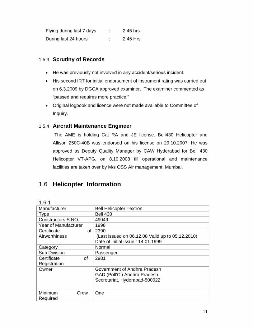
1.6.1 Manufacturer Bell Helicopter Textron Type Bell 430 Constructors S.NO. 49049 Year of Manufacturer 1998 Certificate of Airworthiness
2390 (Last issued on 06.12.08 Valid up to 05.12.2010) Date of initial issue : 14.01.1999
Category Normal Sub Division Passenger Certificate of Registration
2981
Owner Government of Andhra Pradesh GAD (Poll’C’) Andhra Pradesh Secretariat, Hyderabad-500022
Minimum Crew Required
One
12
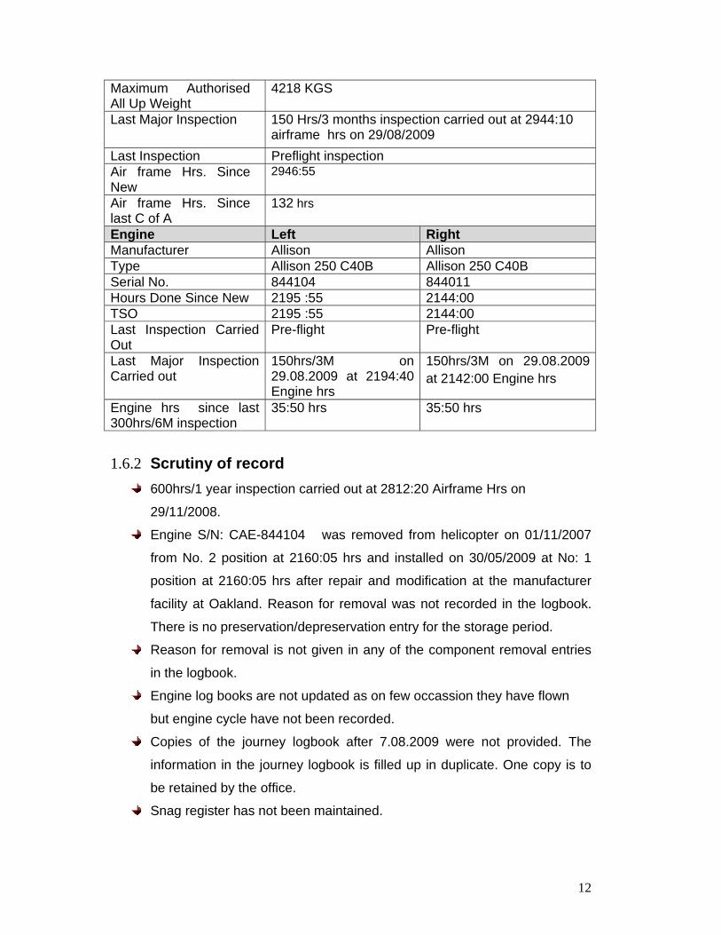
Maximum Authorised All Up Weight
4218 KGS
Last Major Inspection 150 Hrs/3 months inspection carried out at 2944:10 airframe hrs on 29/08/2009
Last Inspection Preflight inspection Air frame Hrs. Since New
2946:55
Air frame Hrs. Since last C of A
132 hrs
Engine Left Right Manufacturer Allison Allison Type Allison 250 C40B Allison 250 C40B Serial No. 844104 844011 Hours Done Since New 2195 :55 2144:00 TSO 2195 :55 2144:00 Last Inspection Carried Out
Pre-flight Pre-flight
Last Major Inspection Carried out
150hrs/3M on 29.08.2009 at 2194:40 Engine hrs
150hrs/3M on 29.08.2009 at 2142:00 Engine hrs
Engine hrs since last 300hrs/6M inspection
35:50 hrs 35:50 hrs
1.6.2 Scrutiny of record 600hrs/1 year inspection carried out at 2812:20 Airframe Hrs on
29/11/2008.
Engine S/N: CAE-844104 was removed from helicopter on 01/11/2007
from No. 2 position at 2160:05 hrs and installed on 30/05/2009 at No: 1
position at 2160:05 hrs after repair and modification at the manufacturer
facility at Oakland. Reason for removal was not recorded in the logbook.
There is no preservation/depreservation entry for the storage period.
Reason for removal is not given in any of the component removal entries
in the logbook.
Engine log books are not updated as on few occassion they have flown
but engine cycle have not been recorded.
Copies of the journey logbook after 7.08.2009 were not provided. The
information in the journey logbook is filled up in duplicate. One copy is to
be retained by the office.
Snag register has not been maintained.
13
Scrutiny of the journey log book for last one year did not indicate any snag
pertaining to transmission or any repetitive snag. On 07.06.2009, torque
had exceedance took place on No.1 engine and it was 105.8% for 1 sec.
Inspection carried out as per MM-Chapter 5.
1.6.3 Aircraft Emergency Locator Transmitter (ELT) ELT Type Pointer 4000-10 and Serial No. 408587 was installed on the
helicopter after NRL test on 18/06/2009. After installation, its operation
was found to be satisfactory. The certificate of Release to service (CRS)
after NRL test and bench check was issued by DGCA approved
organisation. The CRS was valid up to 16/06/2010. The ELT battery was
replaced with new one P/N 2020 ; the replacement of battery was due on
04/2011.
This type of ELT conforms to TSO –C91A specification. This solid state
transmitter operates at emergency frequencies of 121.5 MHz and 243.0
MHz.
1.6.4 Downloading of ECU data The laptop used for the downloading of the data from ECU and IIDS was
in bad state. No exceedance or the engine history data was stored in it
after March 2007. Since March 2007 following exceedance have occurred
for which laptop has been used for clearing the data from the memory after
FADEC degraded, A/RLT for automatic relight, SRT ABT, for ‘Start abort’.
Whenever an OEI condition is detected by the IIDS, the following caution
will appear above the Mast torque: OEI when the engine torque is less
than 80.256, CONT OEI when engine torque is between 90.2 and 92.8%,
2 MIN OEI when engine torque is between 92.9 and 105.3% and 30 SEC
OEI when engine torque is at 105.4% and above. The OEI caution will not
trigger the Master warning/ caution.
e) TRANSMISSION
The transmission is mounted to the cabin roof with a vibration attenuation
system. Power from the engines is transmitted from input quills through
various stages of reduction gearing to obtain necessary torque and speed
for mast and tail rotor drive. A hydraulic pump is mounted on each
outboard quill. Freewheeling clutches are incorporated in outboard quills to
permit disengagement of either engine in the event of engine failure, while
allowing both hydraulic pumps to remain powered.
e-1) TRANSMISSION OIL SYSTEM
The transmission oil system lubricates and cools the transmission. A gear-
driven pump and return screen are mounted in the transmission sump
case. An oil manifold, located on the left side of the transmission, supports
an oil thermostat, oil temperature bulb, oil temperature switch, oil pressure
transmitter, oil pressure regulator, and oil filter. Each transmission/engine
oil cooler consists of two separate, independent cores welded together.
The forward core of each cooler is for the respective engine oil system and
the aft core of each cooler is for the transmission oil system. The oil
coolers are mounted over ducting aft of the aft engine firewall. Oil in the
sump is pumped through an internal line to the manifold and filter. After
passing through the filter, oil is routed by a thermostat either to the oil
cooler or directly to the pressure regulator, depending on the oil
23
temperature. The oil is then routed to eight jets which spray the oil directly
on gears and bearings. A filter bypass valve opens if excessive back
pressure develops as a result of extremely cold temperature or a clogged
filter.
f) ROTOR SYSTEMS
f-1) MAIN ROTOR
The main rotor is a four bladed, all composite bearing less system. The
two yokes bolt directly to the mast flange. A pitch change adapter at the
inboard end of yoke section houses an elastomeric shear restraint and two
elastomeric dampers. The blades have an integral cuff that fits over the
hub yoke and bolts to the pitch change adapter, two more bolts are used
to secure the blade to the outer portion of the yoke. The leading edges of
the blades are fitted with a stainless steel abrasion strip. The end of the
blade is a nickel cap. The stainless strip and nickel cap are used to protect
the rotor blade against erosion.
f-2) TAIL ROTOR
The tail rotor is a two-bladed, semi rigid system mounted on the left side of
the tail boom. All-metal blades incorporate the spherical pitch change
bearings. Rotor flapping is allowed by a delta hinge for stability during
hovering and forward flight.
f-3) ROTOR SYSTEM INDICATORS
Rotor system Indicators consist of a triple tachometer, triple torque meter,
rotor RPM caution light, rotor RPM audio warning signal, and an O/TRQ
caution message on the IIDS.
g) ELECTRICAL SYSTEMS
The electrical system consists of two nonessential, essential, emergency
DC busses and two static inverters.
24
g-1) ELECTRICAL SYSTEM
The DC electrical system is a 28 volt direct current, negative ground
system. Power is supplied by two 30 volt, 200 ampere starter generators
(derated to 180 ampere), one mounted on each engine, and by a 24 volt,
28 ampere hour nickel-cadmium battery located aft of baggage bay. The
electrical power distribution system is composed of two independent
subsystems, which can be interconnected in the event of failure of either
or both generators. Electrical separation between the subsystems is
accomplished with relays, circuit breakers, fuses, and isolation diodes.
Each generator supplies 28 VDC power, controlled by a fault-sensing
voltage regulator (Generator Control Unit), to respective DC main bus
feeder. Each main bus then distributes power to respective non-essential,
essential, and emergency DC busses. Two non-essential busses provide
power to all equipment considered non-essential for flight Two essential
busses provide power to all equipment considered essential for flight
(when either or both generators are operational). Two emergency busses
provide power to all equipment considered essential for flight under all
generator operating conditions, including dual generator failure. The
generators cannot be paralleled and will operate normally at differing
ampere loads. Failure of either generator will render its respective non-
essential DC bus inoperative; however, both emergency busses and both
essential busses are interconnected and will remain powered by the
remaining generator. Power can be restored to the affected nonessential
DC bus through a bus interconnect relay, which will close upon pressing
the BUS INTCON switch in the overhead console. The interconnect relay
will be inhibited from closing if the failure is caused by a bus/feeder fault
(short circuit). This protects the operating generator from being connected
to the faulty system. Also, diodes prevent current flow from the emergency
busses and essential busses back to the non-essential busses. In the
event of a failure of the second generator, both non-essential and both
essential busses will be de-energized. This automatic load shedding
feature allows a minimum of 30 minutes flight with both emergency busses
25
powered by the battery only. Battery power can be applied to both non-
essential and both essential busses by pressing the BUS INTCON switch.
This action closes both the battery relay and interconnect relay, provided
there is no bus/feeder fault. Shortened battery life (less than 30 minutes)
can be expected in this mode. Pressing the BUS DISCON switch will open
both relays to disconnect the battery power from all but the two emergency
busses. The essential busses are fault-protected from each other by the
ESS BUS PWR circuit breaker. The emergency busses are fault protected
from each other by two interconnecting EMER BUS PWR circuit breakers.
The non-essential busses are ground fault-protected from the emergency
busses and essential busses by fuses. The battery is protected from faults
on the emergency feeder circuit to the two emergency busses by the
EMER BUS CONT remote controlled circuit breaker (RCCB). Two 250 VA
inverters provide the 115 VAC and 26 VAC power required for various
navigation and flight control systems. No. I inverter derives its power from
ESSENTIAL BUS 1 while No. 2 inverter derives its power from
EMERGENCY BUS 2.
g-2) ELECTRICAL SYSTEM PRIMARY CONTROLS
Electrical system primary controls consist of a battery switch, generator
switches, inverter switches, bus interconnect and disconnect switches, all
located in the overhead console (figure 1-5) and engine start switches and
a disengage switch located in the glare shield panel.
g-3) GENERATOR SWITCHES
The GEN 1 and GEN 2 switches open and close the generator field
circuits. When either of switches is ON and the output voltage from the
respective generator reaches 25 +0.5 VDC, the generator relay will close
to energize the DC bus and the appropriate GEN caution message will
extinguish. During engine starts using battery power, each GEN switch
should be OFF until its respective engine is operating at Idle (61 ±1% NG).
After the first engine is started, its generator may be switched on to assist
the battery in starting the second engine (generator-assisted start). During
engine starts using external power, both GEN switches should remain
26
OFF until both engines are operating at idle and external power has been
disconnected. A RESET function is provided to reset a generator relay
which has been tripped due to overvoltage, reverse current, or a ground
fault If the malfunction condition persists, the generator relay cannot be
reset and further attempts to reset should not be made.
1.6.6 Load & Trim Sheet The seating arrangement in the passenger cabin was as follows:
1. Passenger No.1 – Left Forward Behind Co-Pilot
2. Passenger No.2 – Right Middle
3. Passenger No.3 – Right Rear
The load and trim sheet is available on the journey logbook (JLB). The
current JLB was destroyed during the crash. The organisation has not
retained the second copy. Based on the available records load and CG
position was calculated and both were found to be within permissible
range.
1.7 Meteorological Information Meteorological briefing for the route VOHY-Chittoor-Ankul Pattru (Nellore Dist)-
Ongole was provided to the pilot of the ill-fated helicopter by Aviation
Meteorological Services (AMS) Begumpet at 6:30 IST of 2nd September, 09. At
the time of briefing METAR 6:10 IST, local forecast of VOHY/VOHS and 100 nm
around with validity period 01.09.2009/3:30 IST – 02.09.2009/11:30 IST, with
validity TAF of 02.09.09/7:30 IST and TAF for other stations on the route with
validity 02.09.09/7:30 IST were provided. Also, en-route synoptic situation were
provided along with the flight folder. The flight folder contained upper
wind/temperature charts of 050 FL, 100 FL and 140 FL and national significant
weather charts.
The pilot was briefed about the presence of CB clouds tops reaching 12 km and
shown the 05:30 IST imagery and satellite bulletin based on 01.09.2009 / 17:30
IST.
27
1.7.1 Met Report: VOHS
Time : 6:40IST Wind : 290/08 KT
Visibility : 4000 M
Weather : FBLRA
Clouds : SCT 1500 FT, SCT 2000 FT, BKN 8000 FT
Temp. : 23˚C
Dew Point : 23˚C
QNH : 1007 HPA 2973INS
QFE : 936 HPA 2764 INS
Trend : No Significant
Time : 7:10 IST Wind : 300/08 KT
Visibility : 4000 M
Weather : FBLRA
Clouds : SCT 1500 FT, SCT 2000 FT, BKN 8000 FT
Temp. : 23˚C
Dew Point : 23˚C
QNH : 1008 HPA 2976INS
QFE : 936 HPA 2764 INS
Trend : No Significant
Time : 7:40 IST Wind : 300/06 KT
Visibility : 4000 M
Weather : FBLRA
Clouds : SCT 1500 FT, SCT 2000 FT, BKN 8000 FT
Temp. : 23˚C
Dew Point : 23˚C
QNH : 1008 HPA 2976 INS
QFE : 936 HPA 2764 INS
Trend : No Significant
28
Time : 8:10 IST Wind : 300/06 KT
Visibility : 4000 M
Weather : FBLRA
Clouds : SCT 1500 FT, SCT 2000 FT, BKN 8000 FT
Temp. : 23˚C
Dew Point : 23˚C
QNH : 1008 HPA 2976 INS
QFE : 937 HPA 2767 INS
Trend : No Significant
Time : 8:40 IST Wind : 310/08 KT
Visibility : 4000 M
Weather : RERA
Clouds : SCT 1500 FT, SCT 2000 FT, BKN 8000 FT
Temp. : 24˚C
Dew Point : 23˚C
QNH : 1009 HPA 2980 INS
QFE : 937 HPA 2767 INS
Trend : No Significant
Time : 9:10 IST Wind : 310/08 KT
Visibility : 4000 M
Weather : RERA
Clouds : SCT 1500 FT, SCT 2000 FT, BKN 8000 FT
Temp. : 24˚C
Dew Point : 23˚C
QNH : 1009 HPA 2980 INS
QFE : 937 HPA 2767 INS
Trend : No Significant
29
Time : 9:40 IST Wind : 310/06 KT
Visibility : 4000 M
Weather : HZ
Clouds : SCT 1500 FT, SCT 2000 FT, BKN 8000 FT
Temp. : 24˚C
Dew Point : 23˚C
QNH : 1009 HPA 2980 INS
QFE : 937 HPA 2767 INS
Trend : No Significant
Time : 10:10 IST Wind : 310/07 KT
Visibility : 4000 M
Weather : HZ
Clouds : SCT 1500 FT, SCT 2000 FT, BKN 8000 FT
Temp. : 25˚C
Dew Point : 23˚C
QNH : 1009 HPA 2980 INS
QFE : 937 HPA 2767 INS
Trend : No Significant
1.7.2 Met Report: VOHY
Time - 08:10 IST Visibility - 5000 m.
Winds - 310/04 kts
Weather - HZ
Clouds - SCT 1500Ft, OVC 8000 Ft
Temperature - 24˚C
DEW Point - 21˚C
QNH - 1008 HPA
QFE - 946 HPA
Trend - No Significant
30
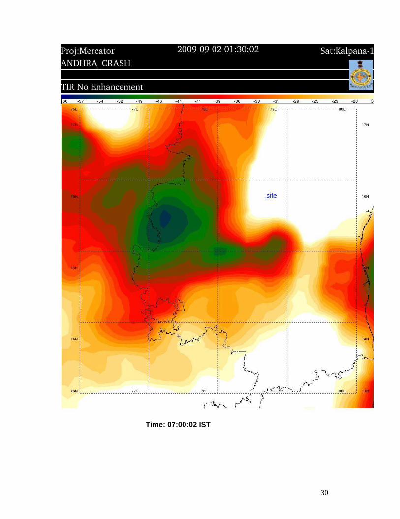
Time: 07:00:02 IST
31
Time: 08:00:02 IST
32
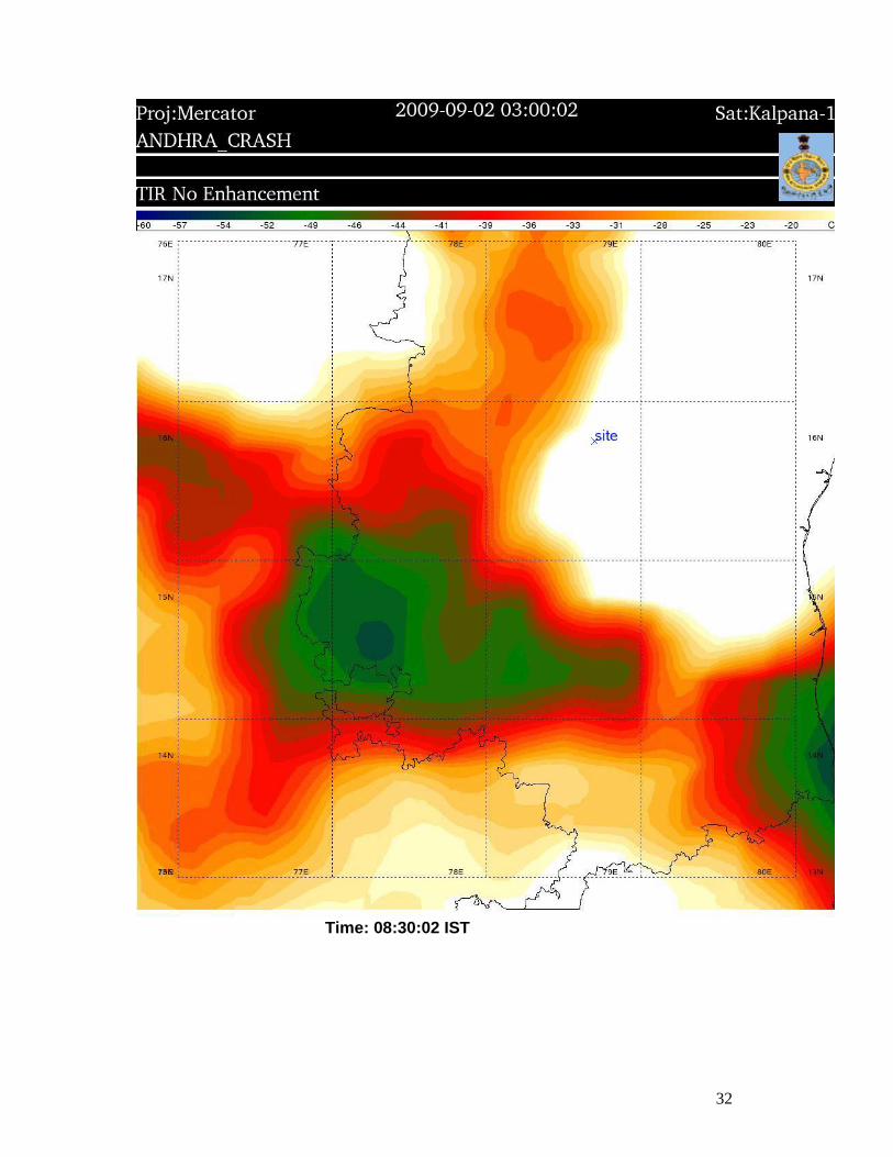
Time: 08:30:02 IST
33
Time: 09:00:02 IST
34
Time: 09:30:02 IST
35
1.7.3 Analysis of the weather Provided by the Indian Meteorological Department.
Following paras list the interpretation/analysis of the weather situation provided
by the Indian Metrological department
1.7.3.1 Current Weather Observations West-northwesterly to northwesterly winds were reported by Begumpet
airport from 08:10 IST to 12:10 IST and the speeds were between 04
knots to 09 knots. The visibility reported was 5000 m throughout the
period and the weather was haze. 3-4 oktas low clouds were observed
with base height 450 m and the sky was overcast with clouds with base
height 2400 m.
The METARs of Shamshabad also shows northwesterly wind but slightly
stronger, i.e. 06 to 08 knots during the period. Visibility was 4000 m only
and rain was observed during the period. Here also, 3-4 oktas of low
clouds with base height 450 m and base height 600 m along with 5-7
oktas of clouds with base height 2400 m were present. By 09:10 IST
visibility improved to 5000 m in haze but again reduced to 3000 m in rain
at 11:40 IST and further to 1500 m in rain at 11:50 IST.
1.7.3.2 Synopsis observations at Kurnool a) 05:30 IST :Wind 02 knots, direction variable overcast sky with 3
okta low clouds with base height 600-999 m, visibility less than 4000 m,
weather continuous rain.
b) 08:30 IST :Wind 5 knots from direction 270 degrees, visibility
4000-10000 m, weather slight rain, visibility less than 4000 m, overcast
sky with 3 oktas low clouds of base height 600-999 m.
36
c) 11:30 IST :Wind 5 knots from direction 270 degrees, visibility
and cloud amount, height of base of cloud remained the same, but
weather was continuous and heavy at the time of observation.
1.7.3.3 Synopsis situation
From the observations of 08:30 IST on 2nd September, rain/thunderstorms
were observed at most places of Telangana and Kurnool reported 4.5 cm
rain. In the forecast valid till 08:30 IST on 4 September, rain/thunderstorm
was forecasted for entire Andhra at many places with heavy rain at
isolated places. From the 08:30 IST observation on 3rd September it is
seen that, rain occurred at many places in Telengana, but Kurnool
reported only 0.7 cm rain. There were no synoptic systems present
exactly over the accident region, however, the southwest monsoon was
active in the neighbouring subdivisions, like Konkan & Goa, Vidarbha,
coastal Karnataka, and Kerala on 2nd September. On 3rd September, also,
monsoon was active in Konkan & Goa, Madhya Maharashtra and
Vidarbha.
1.7.3.4 Interpretation of the satellite imageries
06:00 IST Low clouds with embedded weak convection were observed
over the accident site. CB tops reaching 16 kms were seen
embedded. There were no significant convective clouds
over the eastern sector of the site.
06:30 IST: Increase in convection and aerial extension, specially
towards southeastern sector of the accident site was
observed.
07:00 IST: Further slight increase in convection and aerial extension in
southeast sector of the accident site is observed.
37
08:00 IST: The convection in the southeast sector nearer to the
accident site area decreased. In the rest of the
areas/sectors cloud clusters remain more or less same.
08:30 IST: Almost same situation persisted as 08:00 UTC.
09:00 IST: There is sudden increase in convection over the site and
also the accident site area is fully covered by convective
cloud cluster. The maximum increase in convection found
over southwest sector.
09:30 IST: The accident site is fully covered by convective cloud cluster
and there is further increase in aerial extension of the
convective cloud cluster.
1.7.3.5 The Aviation Forecasts
a) Local forecast for VOHY/VOHS and 100nm around
In the local forecast valid 02/03:30 IST to 02/11:30 IST, the surface wind
was forecast to be 290/10 KT. A reduction of visibility to 3000 m in
moderate rain/drizzle or haze was forecast till 08:30 IST. Possible
formation of isolated Towering Cumulus or CB clouds with base at 750
meter and top height 9000 meter was also forecasted. Moderate to severe
turbulence and icing in CB was forecasted during the period. Warning for
light aircraft “WIND SPEED MAY REACH 20 KT IN GUST FROM 270˚ ”
was also appended to the local forecast.
b) Terminal Aerodrome Forecasts
In the TAF for VOHS and VOHY valid for 02/ 08:30 and 02/ 17:30, 10
knots wind from direction 250˚ was forecasted and the wind was expected
38
to increase to 20 knots in gusts during the forecast period. Also possibility
of development of CB clouds and temporary reduction in visibility from
6000 meter to 3000 meter in thunderstorm and light rain was forecasted
during 02 /15:30 to 02/ 17:30 IST.
In the TAF for Chittoor, Ongole and Krishnapatnam, the possible formation
of CB clouds and temporary reduction in visibility from 6000 meter to 3000
meter in thunderstorm and light rain was forecasted from 07:30 to 14:30
IST.
1.7.3.6 Analysis of convective stability parameters In the analysis of the RS/RW data of nearest available station, Hyderabad,
for the 05:30 IST ascent on 02.09.09, at 925 hPa level, the vertical velocity
(up-draught) was found to be negative (-7.466577E-01 m/s). But at 900
hPa level other vertical velocity was positive (1.071932 m/s). From next
level (850 hPa) vertical velocity was nil. In this analysis only the vertical
velocity due to convection was considered. However by 17:30 IST, the
magnitude of the vertical velocities increased and high values were seen
even up to 113 hPa. The estimated vertical velocity in the lower levels
were of the order of 15 m/s. These observations were at a location of
about 150 km from the accident site and also taken at 05:30 & 17:30 IST.
Hence exact values of up-draught at the site and the time of accident
could not be estimated.
1.7.4 Eyewitness Account: As per the residents of area near the accident site, it was raining heavily in
the area and the visibility was also poor.
1.7.5 Lightning Data: M/s India Precision Lightning Network, who have established lightning
detection network in India as joint collaboration of M/s Rationale
Technologies and TOA system were requested to provide the lighting data
for 2.09.2009. The information provided by them states as follows:
39
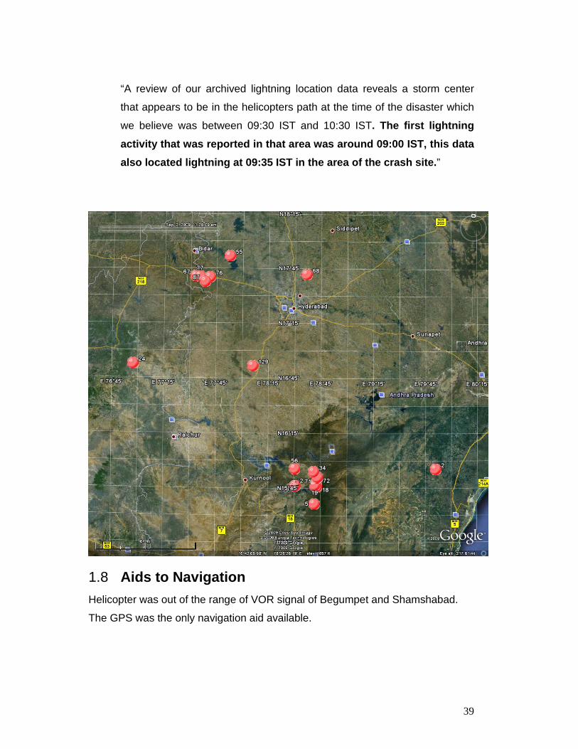
“A review of our archived lightning location data reveals a storm center
that appears to be in the helicopters path at the time of the disaster which
we believe was between 09:30 IST and 10:30 IST. The first lightning activity that was reported in that area was around 09:00 IST, this data also located lightning at 09:35 IST in the area of the crash site.”
1.8 Aids to Navigation Helicopter was out of the range of VOR signal of Begumpet and Shamshabad.
The GPS was the only navigation aid available.
40
1.9 Communication
1.9.1 ATC communication record of Begumpet At 8:29:10 IST - Start up was approved for VT-APG and QNH was given
as 1008
At 8:34:14 IST - Helicopter was given taxi to holding point “B”
At 8:35:42 IST - VT-APG was given departure instructions “VT-APG
cleared to destination Chittoor direct, altitude 5500 feet departure RWY-27
climb RWY heading 4600 feet further with RADAR for departure squawk
2736”. At 8:36:27 IST, it was given take-off clearance from RWY 27.
Helicopter was airborne at 8:37:57 and at 8:38:05 handed over to
approach. Crew copied all the ATC instructions.
1.9.2 Communication Recording of Approach Radar Shamshabad
Helicopter came in contact with Approach Radar Hyderabad at 08:38:50
IST. After identification it was given clearance “Runway heading climb to
5600 feet and reaching 5600 feet turn left set course to HIA (VOR-
Hyderabad)”. The clearance was copied by the helicopter. At 0842:16 IST
helicopter was asked to turn left intercept track to Cuddapah. Then it was
clarified by the helicopter that the destination was Chittoor. At this point
helicopter was on Radial 172˚ from HHY (Begumpet) distance 25.6 miles.
Helicopter requested for the radial 170 for Chittoor. This was approved. At
08:45:00 IST Approach asked for the ETA Chittoor. At 08:45:58 IST, the
crew gave estimate Chittoor as 10:30 IST. At 08:39:41 IST Approach
asked “Confirm destination is Chittoor on Radial 172˚ ”. Helicopter asked if
they could maintain the present course. ATC asked “Report Established
Radial 172˚ from HHY”, which was affirmed by the helicopter. At 09:03:20
approach asked helicopter to report at 50 miles from HHY. The helicopter
gave the present position as 46 miles maintaining 5600 feet. Approach
asked helicopter “Report in contact with Chennai Control 118.9 alternate
Chennai Radio.” Helicopter affirmed that they were in contact with HF. At
41
09:03:45 IST helicopter asked “May we maintain 5600 or 5500 feet”.
Approach cleared it to descent to 5500 feet at 50 miles. At 09:06:22 IST
helicopter confirmed with approach that Chennai area control frequency as
118.9. At 09:12:34 IST helicopter informed the approach that they have
contacted the Chennai radio and the next contact is at 09:30 IST. The
frequency change was approved and radar services terminated. The last
radio contact with Hyderabad approach was made at 09:12:52 IST.
1.9.3 ATC communication record of Chennai Helicopter contacted Chennai radio at HF frequency 6655KHZ at 08:59:56
IST and passed the information that they are at 5500 feet; estimate
Chittoor at 10:30 IST; CM on board; departure clearance issued to them
by Begumpet. HF Chennai advised helicopter to make next contact at
09:30 IST.
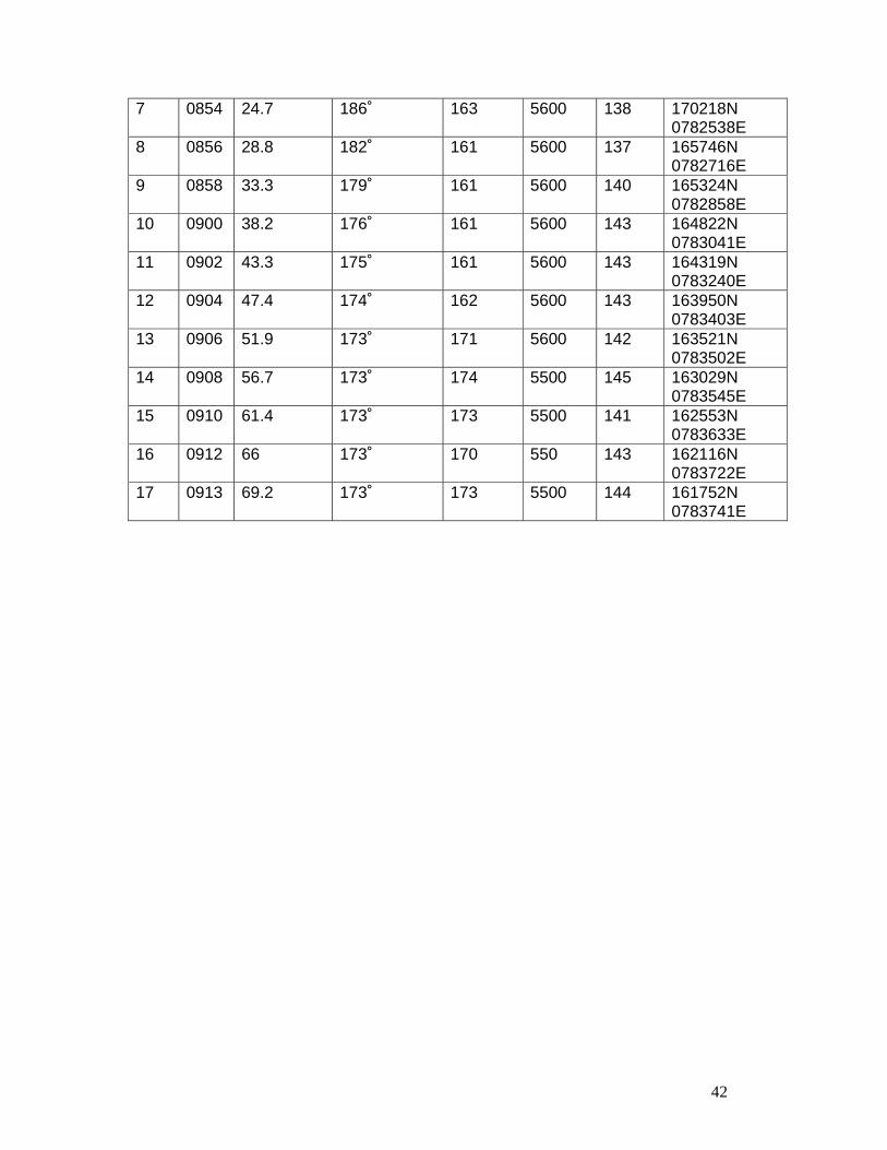
1.9.4 Radar Recording of Shamshabad
The helicopter was painting on the approach radar Shamshabad up to
79.2 nm from it. The radar recording of Approach Radar Shamshabad was
obtained and on its basis the position of helicopter w.r.t. Begumpet was
determined as given below:
S.No Time
(IST)
Distance from Begumpet (nm)
Bearing w.r.t.
Begumpet (HHY)
Heading (Approx)
Altitude (Ft)
Ground Speed (Kts)
Lat/Long.
1 0838 Airborne from Begumpet
Overhead Begumpet RWY 27
RWY heading
2000 059 172657N 0782655E
2 0844 7.9 245˚ 172 5600 104 172325N 0782011E
3 0846 9.8 222˚ 174 5600 136 171938N 0782109E
4 0848 13 206˚ 171 5600 134 171444N 0782214E
5 0850 15 202˚ 172 5600 135 171037N 0782255E
6 0852 20.8 191˚ 163 5600 135 170622N 0782403E
42
7 0854 24.7 186˚ 163 5600 138 170218N 0782538E
8 0856 28.8 182˚ 161 5600 137 165746N 0782716E
9 0858 33.3 179˚ 161 5600 140 165324N 0782858E
10 0900 38.2 176˚ 161 5600 143 164822N 0783041E
11 0902 43.3 175˚ 161 5600 143 164319N 0783240E
12 0904 47.4 174˚ 162 5600 143 163950N 0783403E
13 0906 51.9 173˚ 171 5600 142 163521N 0783502E
14 0908 56.7 173˚ 174 5500 145 163029N 0783545E
15 0910 61.4 173˚ 173 5500 141 162553N 0783633E
16 0912 66 173˚ 170 550 143 162116N 0783722E
17 0913 69.2 173˚ 173 5500 144 161752N 0783741E
43
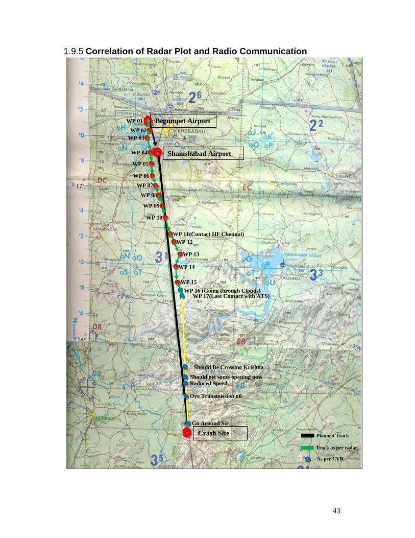
1.9.5 Correlation of Radar Plot and Radio Communication
Shamshabad Airport
Crash Site
Begumpet Airport WP 01 WP 02
WP 03
WP 04
WP 05
WP 06
WP 07
WP 08
WP 09
WP 10
WP 11(Contact HF Chennai)WP 12
WP 13
WP 14
WP 15WP 16 (Going through Clouds)
WP 17(Last Contact with ATS)
Should Be Crossing Krishna
Should get some opening now Reduced Speed
Oye Transmission oil
Go Around Sir
Planned Track
Track as per radar
As per CVR
44
1.10 Aerodrome information 1.10.1 Hyderabad airport is located 7 kms. from Hyderabad Railway Station.
The ARP coordinates of Hyderabad Airport are 172711.2N 0782729.1E
and elevation is 531.3 meters. IFR/VFR types of traffic are permitted with
24 hours operation. The airport has DGCA licence No. AL/Public/011.
1.10.2 Meteorological Services It has class-I Met Office with 24 hours of service. The trends are issued
from 05:40 to 21:40 IST every 30 minutes and 16:40 to 23:40 IST hourly.
Hyderabad ATS units are also provided with the information.
1.10.3 Diversion Helipads Within close proximity of accident site, the diversion helipad could be
Atamkur to the right of the flight path. Approximately six minutes before
the helicopter encountered transmission oil snag, the diversionary helipads
available were Achempet, Kurnool and Atamkur. Achempet was on the
track while other two were to the right of the track.
1.10.4 Search and Rescue Services The Search and Rescue Service in India is organized by the Airports
Authority of India in collaboration with the Ministry of Defence, which has
the responsibility for making the necessary resources available. Airports
Authority of India has prepared a manual for search and rescue operation.
The relevant extract for the manual for organizing search and rescue are
as follows:
Head of SAR Services Chennai
The General Manager (Aerodromes) Airports Authority of India, Chennai
Airport is the head of the Search and Rescue Services of Southern
Region.
45
Agencies involved in SAR operations
Various other departments of the Central and State Governments viz.
Railways, P&T, All India Radio Police and District Collectors/Magistrates
etc., Municipal and Local Bodies, Airline Operators, Flying Clubs,
Professional Pilots, Mercantile Marine, Port Trusts and Armed Forces are
available for Search and Rescue missions as and when required.
Delimitation of the Area of Responsibility
The SAR area of Chennai Search and Rescue Region is the area
contained within the boundaries of Chennai Flight Information Region.
The coordinates of Chennai Flight Information is as follows:
1800N 7600E to 1800N 8100E to 1630N 8300E to 1400N 9200E to
1330N 9425E to 0600N 9425E to 0600N 9200E to 1000 N 8000E to
0600N 7800E to 0600N 7200E to 1500N 7200E to 1500N 7600E to
1800N 7600E
RCC Chennai – Functions
The RCC Chennai is responsible for promoting efficient organization of
SAR Services and co-ordinating conduct of SAR operations within
Chennai SRR. RCC is responsible for drawing up a detailed plan for the
conduct of SAR in its area, which includes the –
(a) Organisation of the quickest possible means of communication in
the area and with adjacent areas, for exchange of search and
rescue information;
(b) Organisation of rescue units and designation of alerting posts;
(c) Coordination with services and organizations likely to be useful;
(d) Responsibilities of personnel assigned to search and rescue;
(e) Location, call signs, hours of watch and frequencies of radio
stations maintaining watch for the purposes;
46
(f) Manner in which search and rescue is to be conducted;
(g) Actions planned jointly with adjacent Rescue Coordination Centers
(h) Any special provisions necessary or incidental to the conduct of
search and rescue.
Information regarding State of Emergency of an Aircraft
An ATS Unit may generally become aware that an aircraft is in a state of
emergency in one or more of the following ways:
a) Report to that effect by the aircraft itself.
b) Failure of an aircraft to report position or to respond to calls either from
the ground or from other aircraft.
c) Failure to appear on radar when normally it should have appeared or
sudden disappearance from radar screen.
d) Emergency indications on ADS and Secondary Surveillance Radar
(SSR).
The following SSR Code will be applicable relating to the nature of an
emergency as below:
State of Emergency: Mode A Code 7700
Two-way communication lost: Mode A Code 7600
Unlawful interference: Mode A Code 7500
e) Reports by Pilots of other aircraft or ships at sea.
f) Reports from Airline Operators who may have received the information
on their Company channels.
g) Reports from members of public.
h) Alert messages received via Satellites relayed by INMCC Bangalore.
Declaration of Emergency
Notification of emergency : Without prejudice to any other circumstance
that may render such notification advisable ATS Units shall notify RCC
Chennai immediately, that an aircraft is considered to be in a state of
emergency.
47
Phases of Emergency
a) Uncertainty Phase
i) When no communication has been received from an aircraft within a
period of 30 minutes after the time, a communication should have been
received or from the time an unsuccessful attempt to establish
communication with such aircraft was first made, whichever is earlier
or when
ii) An aircraft fails to arrive within 30 minutes of the estimated time of
arrival last notified to or estimated by Air Traffic Services Unit,
whichever is the later except when no doubt exists as to the safety of
the aircraft and its occupants.
b) Alert Phase
i) Following the uncertainty phase, subsequent attempts to establish
communication with the aircraft or enquiries to other relevant sources
have failed to reveal any news of the aircraft, or when
ii) An aircraft has been cleared to land and fails to land within five
minutes of the estimated time of landing and communication has not
been re-established with the aircraft’ or when
iii) An aircraft is known or believed to be the subject of unlawful
interference.
c) Distress Phase
Following the alert phase further unsuccessful attempts to establish
communication with the aircraft and more widespread unsuccessful
enquiries point to the probability that the aircraft is in distress.
48
Initiation of Action
On receiving information that an aircraft is in a state of emergency, the
FIC Coordinator should initiate action immediately.
Aircraft whose position is unknown
In the event that an emergency phase is declared in respect of an aircraft
whose position is unknown and may be in Chennai or any other SRR the
following will apply:
If RCC Chennai is notified of an emergency phase and it is unaware of
other centers taking appropriate action, RCC Chennai will assume
responsibility for initiation of suitable action in accordance with these
procedures and confer with neighboring RCCs to designate an RCC to
assume responsibility in this regard.
Actions during Emergency Phase
Actions to be taken when aircraft enters into uncertainty phase:
i) The flight of the aircraft involved shall be plotted on a chart by FIC in order
to determine the probable future positions of the aircraft at its maximum
range of action from its last known position. The flight of the aircraft
known to be in the vicinity of the aircraft involved should also be plotted to
determine the maximum endurance.
ii) When FIC decides that an aircraft is in a state of emergency, it shall, as
soon as possible inform other aircraft known to be in the vicinity of the
aircraft involved, the nature of the emergency. At the discretion of the
RCC other SAR units and RCCs may be alerted.
49
Alert Phase SAR action is normally initiated when the state of emergency enters the
Alert Phase. The GM (aero) besides informing all concerned Chennai at
his discretion will keep the Chairman, AAI (NAD), New Delhi informed
through Member (O) and ED(ATM).
i) Send ALERFA message to concerned neighboring FICs, destination,
alternate and other Aerodromes on the route where the aircraft could have
landed.
ii) Plot the progress of the flight in Chennai FIR, its point of entry, route
followed, last position known or reported for further action.
iii) If the overdue aircraft is over the land, informs the Duty Officer, IAF,
Tambaram to relay message to Officer Commanding to keep the search
aircraft on standby.
iv) Maintain watch on frequencies on which the aircraft was last working and
do blind weather broadcast for the destination and alternate aerodromes,
if the weather condition at Chennai is below minima, if the destination of
the involved aircraft is Chennai.
v) Inform Met Officer to send to FIC in plain language route forecast etc., for
the route involved up to destination and alternate aerodromes.
1.11 Flight Recorders
The helicopter is equipped with CVR but not DFDR (neither it is required to be
equipped with DFDR). The CVR was recovered in damaged condition. It was
decoded at NTSB facility at Washington D.C in presence of representative of
committee of inquiry.
Salient Points from the CVR transcript are as under:
The Flying Crew was well aware of inclement weather enroute as the same
was discussed, visually observed and interpreted the weather Radar picture
throughout the flight.
50
* The Crew was in contact with Hyderabad approach on VHF
frequency till they were asked to change over to Chennai control
after establishing the contact with Chennai on HF frequency.
* The Crew was not sure about Chennai frequency and was debating
among themselves about the Chennai frequency given to them by
Hyderabad approach which shows poor flight planning.
* The PIC was well aware of the repercussions of bad weather and
instructed the Co-Pilot to keep his hand under the collective to safe
guard against exceedance of Torque and up and down draughts
and turbulence.
* The Crew noticed transmission pressure display on IIDS and failed
to correlate with other indication associated with it. They wanted to
refer the emergency encountered with the help of emergency
checklist but could not locate the emergency either in the
emergency checklist or in the Flight Manual.
* The CVR transcript shows that they were expecting some
improvement in weather conditions after crossing Krishna River
which was flowing at right angle to the flight path in hilly region.
* The Crew got so engrossed with the emergency and lost situational
awareness of extreme bad weather ahead.
* There were repeated warnings from Co-pilot to Go Around due to
close proximity of ground which he may have realized either with
the help of Radio altimeter or may have sighted the obstruction
momentarily, the PIC failed to react to the situation.
* The CVR transcript shows that there was poor CRM amongst the
Crew at any given stage of flying.
1.12 Wreckage and Impact Information Accident site is approximately 26 km from Atamakur in the dense forest. The
coordinates of the accident site are N 15° 47´04.7”, E 078° 42´40.9¨.Accident site
is at the slope of a hill. The surface is rocky. Due to impact the helicopter had
51
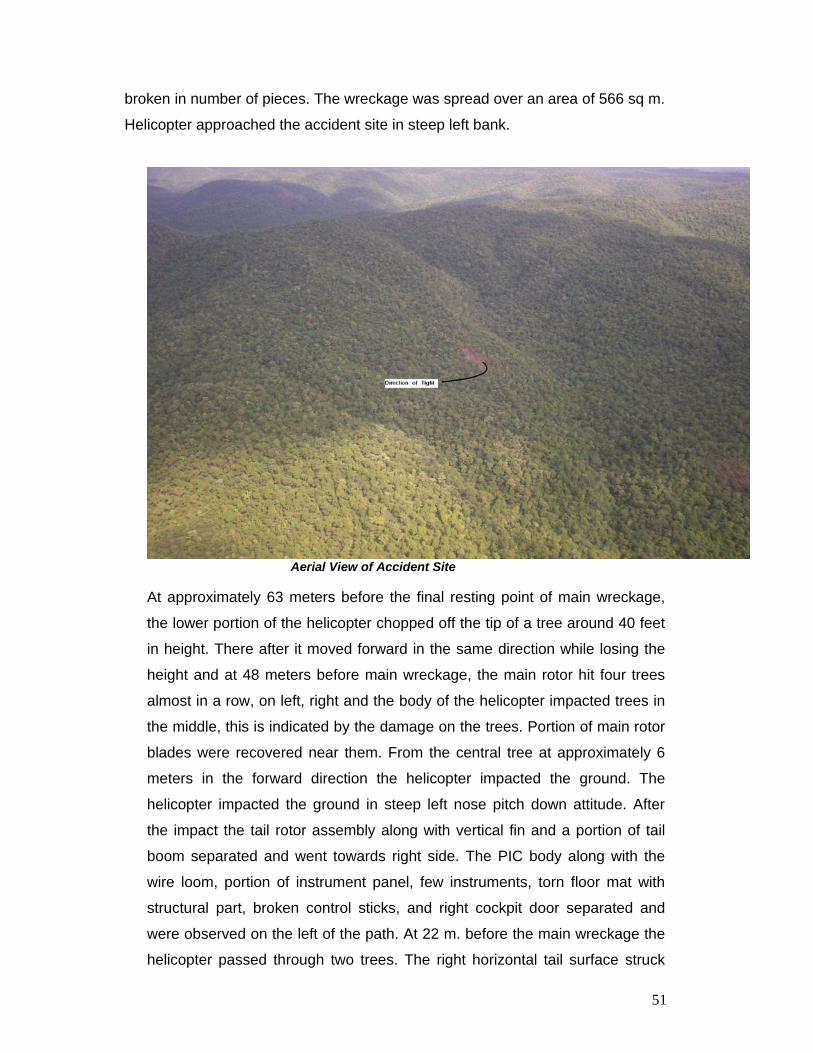
broken in number of pieces. The wreckage was spread over an area of 566 sq m.
Helicopter approached the accident site in steep left bank.
Aerial View of Accident Site
At approximately 63 meters before the final resting point of main wreckage,
the lower portion of the helicopter chopped off the tip of a tree around 40 feet
in height. There after it moved forward in the same direction while losing the
height and at 48 meters before main wreckage, the main rotor hit four trees
almost in a row, on left, right and the body of the helicopter impacted trees in
the middle, this is indicated by the damage on the trees. Portion of main rotor
blades were recovered near them. From the central tree at approximately 6
meters in the forward direction the helicopter impacted the ground. The
helicopter impacted the ground in steep left nose pitch down attitude. After
the impact the tail rotor assembly along with vertical fin and a portion of tail
boom separated and went towards right side. The PIC body along with the
wire loom, portion of instrument panel, few instruments, torn floor mat with
structural part, broken control sticks, and right cockpit door separated and
were observed on the left of the path. At 22 m. before the main wreckage the
helicopter passed through two trees. The right horizontal tail surface struck
52
the tree on the right and this portion of the tail boom separated from the
helicopter. The Copilot body was further on the left along with the frame of the
seat. At 15m from this point, Left wing upper portion, burnt VIP seat, and
“passenger no.1” body was recovered. The back of the body bore signs of fire
burn. The right wing upper portion with soot deposit was recovered 15 m to
the right of main wreckage. The helicopter moved forward, its parts
progressively separated and finally came to rest after impacting a group of
trees and caught fire. The main wreckage was resting on left side and turned
by 90˚ to the direction of motion.
No aircraft part was recovered before the tree where the initial impact was
made. Ground marks of fire/soot were observed from 22 m before the main
wreckage on the tree and the stones. Marks of the fire were observed on the
leading edge of the one tail rotor blade, left horizontal stabilizer, lower portion
of tail boom on the left and floor mat located near the horizontal stabilizer.
Detailed wreckage diagram is given as appendix ‘A’.
View of the site with direction of flight
53
1.12.1 Fuselage
a. Fuselage was broken in to number of pieces and spread along the
direction of the motion. Due to impact the nose compartment had
shattered, the avionic components, electrical components, radar and
CVR housed in it were scattered near the point of initial impact with the
ground. All the units were damaged/stripped open. A portion of the
right side of the cockpit along with the instrument panel had separated
initially. Both the seats in the cockpit were shattered. Left side crew
seat belt was buckled on the body and attached to the frame. The
cockpit doors and frames were broken and bent. Left cockpit door was
recovered with the lock in engaged mode. The right cockpit door was
bent outward. Control sticks of both sides were bent and broken, top
panel of the cockpit was located at the main wreckage position along
with overhead electrical console, center pedestal in damaged condition
and bore fire damage/soot deposit. All the passenger seats frames
were shattered. Passenger door of the right side with the glass and
upper portion of the window frame broken and baggage compartment
door in the locked condition was recovered. Soot deposits were
observed on the rear panel of the baggage compartment. The fuselage
fuel tank, auxiliary fuel tank were ripped open. Fuel tank rear spar with
a portion of ribs attached, partially burnt bladders, fuel filler neck along
with fuselage panel were recovered. Fire damage was seen on the
spar. The warping and burning of the skin had taken place. The portion
of skin on right side was missing.
b. Following items were recovered :
Pilot seat frames, Co-pilot seat frame, DR Compass, Altimeters,
1&2”, “BUS INCON”, “GEN2 FIELD”, “GEN1 FIELD” were observed to
be out.
Switches Position TEMP CONT Middle
WSHLD WIPER HIGH
ENG1 (FADEC) AUTO MODE
ENG2 (FADEC) MAN MODE
ENG2 (FIRE) ARM
d. Cockpit Instrument Readings Instrument Reading Air Speed Indicator (Left) Out of Scale
Air Speed Indicator (Right) 160 kts
Vertical Speed Indicator 3500 ft/min
(descent)
Helicopter Clock 09:29
Altimeter Pressure Setting 1007.5 MB
Altitude 1230 feet
55
1.12.2 Stubwing : Both the left and the right stubwings had shattered. Upper skin panel of both
the stubwings were recovered. They showed the sign of axial load with bent
line near the step portion. Soot deposits were seen on the right wing upper
panel and it was recovered around 50 feet from the main wreckage towards
its right. The forward and the bottom portions were missing. The spar in
continuation of the fuselage tank was available on both left and right side.
1.12.3 Landing Gear Skids assembly was broken into pieces. The cross tubes and the skids had
separated.
1.12.4 Engines
Both the engines were recovered at the site of main wreckage. They were
located in their housing on top of fuselage. Right engine had extensive fire
damage. The accessory gearbox casing was completely burnt and starter
generator had shattered. Oil and transmission cooler along with the blower
had separated. No debris was seen in the inlet and exhaust of both the
engines.
1.12.5 Main Transmission The main transmission was located at its position on the top of the fuselage.
The right input drive quill adapter had separated from the transmission. All the
mounts were intact. Tail rotor quill and the rotor brake assembly were intact.
1.12.6 Main Rotor
Main rotor assembly was intact. Only 1/4th of the blade length was available.
The blades displayed significant leading edge damage, with middle portion
and trailing edge of the composite blades shattered. The damage observed to
the main rotor blades was consistent with the blades impacting with power
being applied.
56
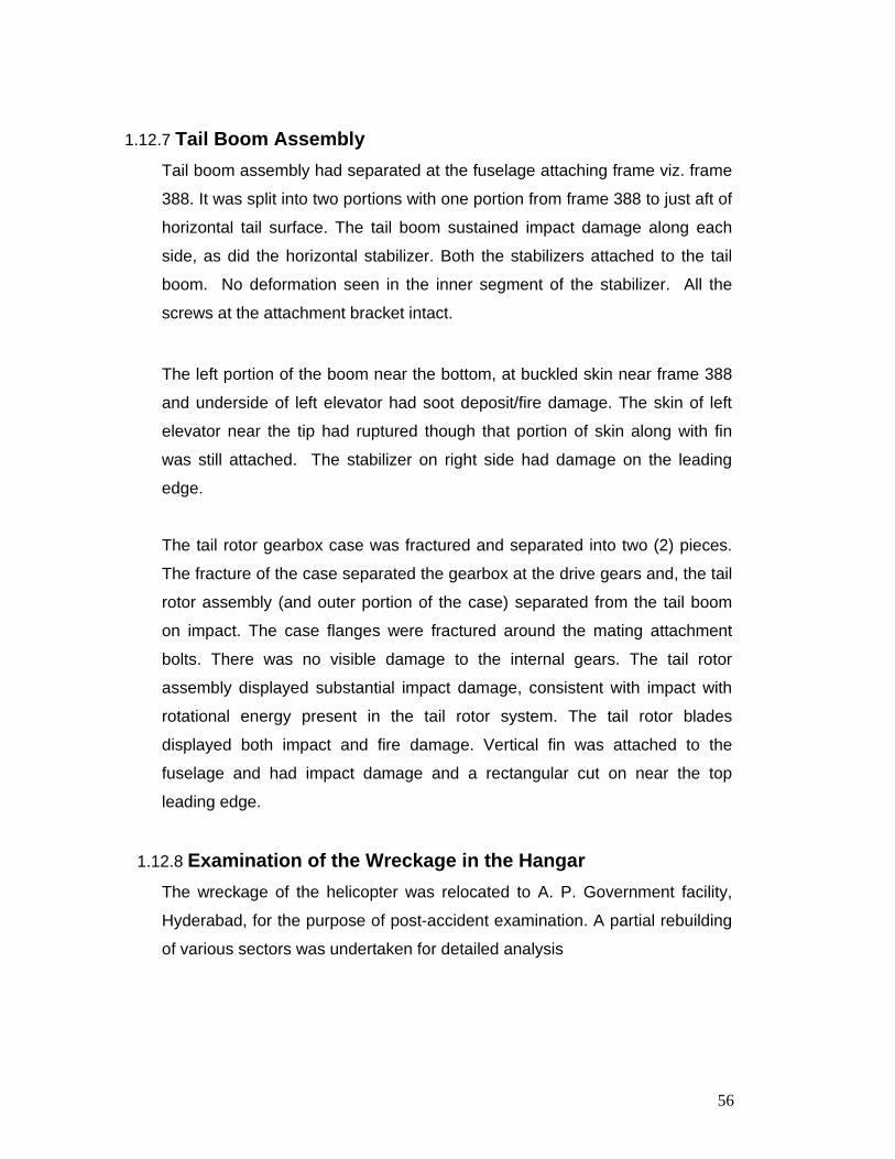
1.12.7 Tail Boom Assembly
Tail boom assembly had separated at the fuselage attaching frame viz. frame
388. It was split into two portions with one portion from frame 388 to just aft of
horizontal tail surface. The tail boom sustained impact damage along each
side, as did the horizontal stabilizer. Both the stabilizers attached to the tail
boom. No deformation seen in the inner segment of the stabilizer. All the
screws at the attachment bracket intact.
The left portion of the boom near the bottom, at buckled skin near frame 388
and underside of left elevator had soot deposit/fire damage. The skin of left
elevator near the tip had ruptured though that portion of skin along with fin
was still attached. The stabilizer on right side had damage on the leading
edge.
The tail rotor gearbox case was fractured and separated into two (2) pieces.
The fracture of the case separated the gearbox at the drive gears and, the tail
rotor assembly (and outer portion of the case) separated from the tail boom
on impact. The case flanges were fractured around the mating attachment
bolts. There was no visible damage to the internal gears. The tail rotor
assembly displayed substantial impact damage, consistent with impact with
rotational energy present in the tail rotor system. The tail rotor blades
displayed both impact and fire damage. Vertical fin was attached to the
fuselage and had impact damage and a rectangular cut on near the top
leading edge.
1.12.8 Examination of the Wreckage in the Hangar
The wreckage of the helicopter was relocated to A. P. Government facility,
Hyderabad, for the purpose of post-accident examination. A partial rebuilding
of various sectors was undertaken for detailed analysis
57
1.12.8.1 Examination of the Fuselage and Tail Boom
Forward fairing, Transmission cowling, air inlet cowling, upper engine cowling
and fairing was missing/split into fragments. Roof of the cockpit had spilt in
three parts viz. Cockpit roof, Transmission deck and engine web. Fuselage
shell consisting of frames and longitudinal members had shattered. Tail boom
had separated at fuselage attaching frame.
Transmission deck: both the hydraulic modules were intact. All the four
manifold intact, all the hydraulic lines are connected. Three front and three
rear Bell crank attachments separated.
Transmission Deck
Engine Web Left Top Panel of the No.1 Engine: Decolouration and bluish marks seen near
the exhaust and forward portion on the RHS. On the inner side completely
covered with the soot. Burning of surface seen in patches and white deposit
were seen near the exhaust.
Bottom Portion of the No.1 Engine: Warping of the surface seen in damage
condition due to fire. Metallic hose burnt. Bluish and brown marks observed.
58
No.2 Engine Bottom Panel: The surface colour is brown and bluish. White
material deposit, thick soot deposit and charring of the metal on the front side
out board. Lower panel cover, bluish and brown marks at leading edge.
Bottom surface warping seen.
Right Side Aft Panel: Side portion heavy soot deposits are seen. A large
portion of the grill was burnt.
Exhaust Panel: Top portion, decolouration, bluish and brown marks observed.
White deposits were seen in the direction of flow in the exhaust. Inner side
soot deposit and white deposit seen, bluish and brown patches observed.
Rear Panel: Showed sign of fire damage/soot deposit. On the top, mesh is
intact. On the left side a portion of wire mesh is burnt. The portion shows fire
damage, discoloration and soot deposit.
Fire Wall Front Side: Sign of fire damage observed and deformed due to
impact. Metal puddle is seen on RHS flowing downward. The fire wall
material is shattered and burnt.
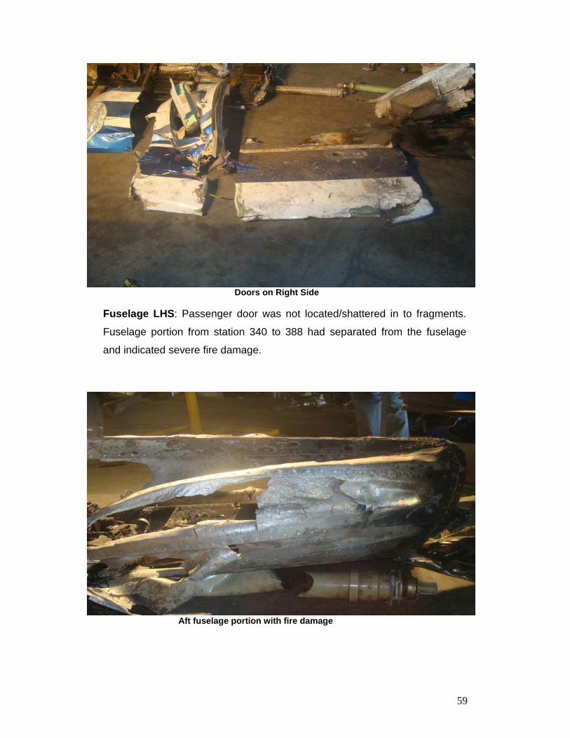
Fuselage RHS: Cargo door fully recovered. Door is in locked position and
separated from the fuselage. Passenger door glass with frame separated.
59
Doors on Right Side
Fuselage LHS: Passenger door was not located/shattered in to fragments.
Fuselage portion from station 340 to 388 had separated from the fuselage
and indicated severe fire damage.
Aft fuselage portion with fire damage
60
Tail Boom Tail Boom: Separated at fuselage attachment to the tail boom. The first frame
is damaged and about ¼ portion is missing. All the eight longerons attached,
however, broken at attachment point due bending. The impact was from the
left bottom. Soot deposit, decolouration and burning of the paint seen on the
left bottom portion. Elsewhere in the left side soot deposit seen. Tail boom
fractured at tail boom frame No.10. No fire damage and separation occurred
due to bending and rupture. End portion of the frame No.10 has impacted. All
fasteners of the drive shaft upper panel were intact. No fire damage or soot
deposit seen.
Vertical Fin: Entire length of the vertical fin recovered near the root end
trailing edge there is impact causing compression cord wise and in vertical
direction. On the left side near leading edge there is a rectangular cut 5cm x
2cm. Leading edge ripped open about 12’inch leading edge impact and
flattened. TGB housing attached along with portion of tail drive shaft. TGB
mounting is in place. TGB separated from the housing. No fire damage
observed.
Tail Gear Box: Casing broken. Pitch change link broken from airframe
attachment. Input rod from the cockpit broken. However, the linkages are
intact. No fire damage.
Tail Rotor Blade: Tail rotor blade separated from the gear box. Both the
blades attached to the hub. No damage in the leading edge. Blade S/N A-
1895 intact with impact damages. No fire damage. Blade S/N A-1892 only
leading edge available, a portion of honeycomb near the root end available.
Ripped open at the trailing edge and has fire damage / soot deposit. Leading
edge also indicate signature of high temp. Bulbs of the paint were formed.
Tail Drive Shaft: All the four segments of the tail drive shaft recovered. No.1
segment separated on the MGB side due to tear and torsion. Several scoring
marks observed on the shaft. At the rear end the Thomas coupling is intact.
None of the fasteners are adrift. Splines are satisfactory. No.2 Segment
61
came out from the spline. The inner splines are intact. Near the forward
portion soot deposit and brown colouration is due to high temperature. On the
rear, the shaft was ruptured. Splines are satisfactory and the coupling is
attached. Third segment intact, attached at both ends and tail boom. No.4
Segment Split in two pieces. On the front end the coupling attached. Inner
splines were found intact.
Tail boom and Tail rotor drive Shaft
Wire locking and other fasteners available. No fire damage. Rear portion
attached to the TGB. Coupling is intact and free to rotate.
Left Stabilizer: Auxiliary fin detached along with a portion of stabilizer.
Leading Edge slat is intact. Compression is due to impact from the tip
towards the root. On the top surface soot deposit and burning of the paint
observed in the out board portion. Soot deposit seen on the inner surface of
the stabilizer skin. Entire bottom surface shows soot deposit, burning of paint
and discoloration.
62
Right Stabilizer: Attached with the tail boom. Auxiliary fin attached. Bottom
portion of the auxiliary fin bent due to impact. Leading edge slat impacted at
the out board portion of the leading edge. Compression is due to hit with the
tree. All fasteners of drive shaft upper panel were intact. No fire damage
and soot deposit seen.
1.12.8.2 Examination of the Cockpit The roof panel of the fuselage is deformed and bent inward due to impact
from the front and left side. It is covered with soot. Only a portion frame of left
and right cockpit door and frame was recovered. The forward edge of the
right door is battered and bent outward in the forward direction. The lower
portion of the frame is also bent in the forward direction. The left door is
pushed in the backward direction. The frame is also buckled. Scissor
assembly is damaged and separated. The damage pattern indicates forward
and vertical impact on the left side and vertical impact on the right side.
Cockpit doors with Upper Portion
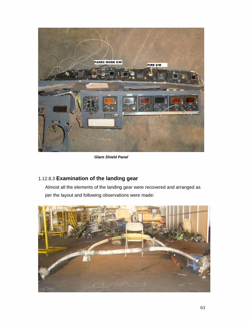
The glare shield panel indicates that the No.2 engine fire was armed. No.1
engine was in FADEC auto mode while No.2 engine was FADEC manual
mode.
63
Glare Shield Panel
1.12.8.3 Examination of the landing gear
Almost all the elements of the landing gear were recovered and arranged as
per the layout and following observations were made:
64
• Skid gear separated from the fuselage at the attachment points.
• Forward Cross tube on the left side was flattened and attachment to the
skid was served and twisted backward.
• Left Skid had served near attachment at forward cross tube and aft cross
tube and broken into three pieces.
• Right Skid was broken into five pieces.
• Aft cross tube support beam shifted towards the left.
Damage to the landing gear indicates that heavy impact was felt on the left
side in the vertical and longitudinal direction which cased the flattening and
twisting backward of the forward cross tube on the left side.
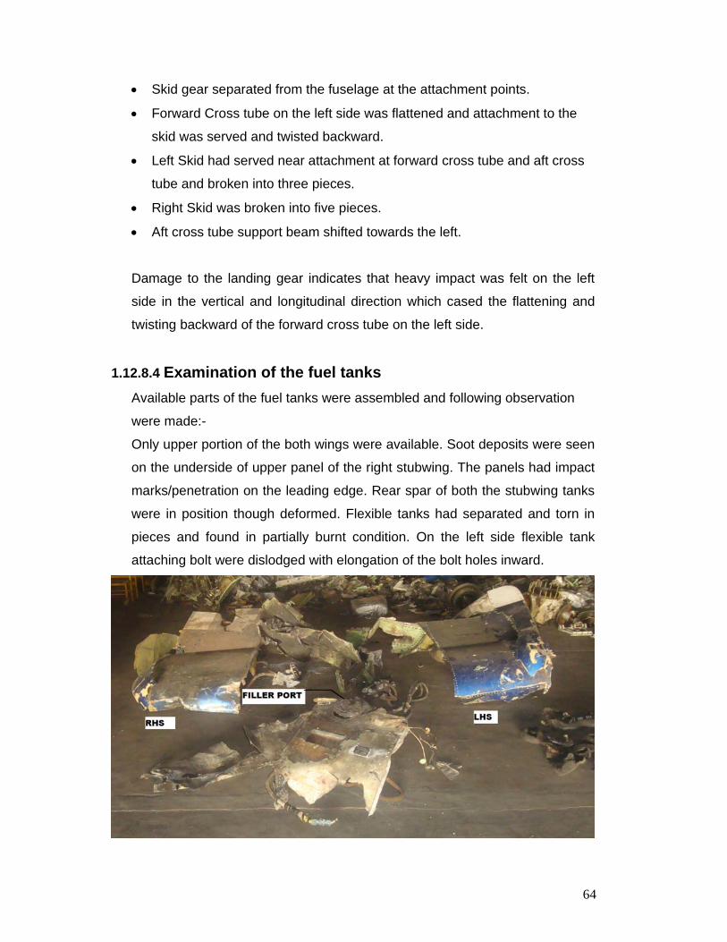
1.12.8.4 Examination of the fuel tanks
Available parts of the fuel tanks were assembled and following observation
were made:-
Only upper portion of the both wings were available. Soot deposits were seen
on the underside of upper panel of the right stubwing. The panels had impact
marks/penetration on the leading edge. Rear spar of both the stubwing tanks
were in position though deformed. Flexible tanks had separated and torn in
pieces and found in partially burnt condition. On the left side flexible tank
attaching bolt were dislodged with elongation of the bolt holes inward.
65
Left wing fairing separated at the bolt line. Holes failed in the inward direction.
Central fuel tank rear spar was available and showed signs of severe burns
on the right side. Main tank and auxiliary fuel caps were recovered. Auxiliary
fuel tank was totally burnt. Both sides of wing tip fairings have shattered in
pieces.
1.13 Medical and Pathological Information 1.13.1 The post-mortem examination of crew and passengers was carried out by
the Forensic Science Department of Kurnool Medical College. The
examination revealed that the clothes of all the bodies were torn and
stained with blood, mud, pieces of vegetations, electric wires, seat belts
and glass were found embedded in the muscular tissues/viscera. The
facial features were intact and identifiable but the skulls were crushed,
with the cranial cavity exposed and brain tissues either oozing out or
missing. The limbs were fractured or separated. The abdominal and
thoracic cavities were exposed. Most of these injuries were anti-mortem.
Fire injuries were observed on occupants seated on left side. The cause
of death has been given to be shock and hemorrhage resulting from
multiple injuries.
1.13.2 The postmortem reports were referred to DMS (CA) for his opinion. As per
opinion expressed by him on the reports in respect of crew/passengers
suggest the following:
Severe decelerative stress leading to multiple fractures/bony injuries
indicating very high speed impact.
Post crash fire for a short duration due to extensive fuel spill – Flash
burns.
66
1.14 Fire Soot deposit/fire damage was observed on the left side aft of left wing.
The fire damage/soot deposit followed the air pattern. The soot deposit
was not in the upward direction. These parts had separated subsequently
along the direction of motion before the helicopter wreckage finally came
to rest. Fuselage portion aft of the baggage compartment had severe
burns and warping of the skin. Bodies of the passengers which were
thrown out had fire injuries on the back. This indicates the fire was
triggered either during impact with the trees or after the first impact with
the ground, the fire was of moderate intensity and of short duration. Also
there were no signs of fire during the flight like metal spattering along the
flight direction or brooming.
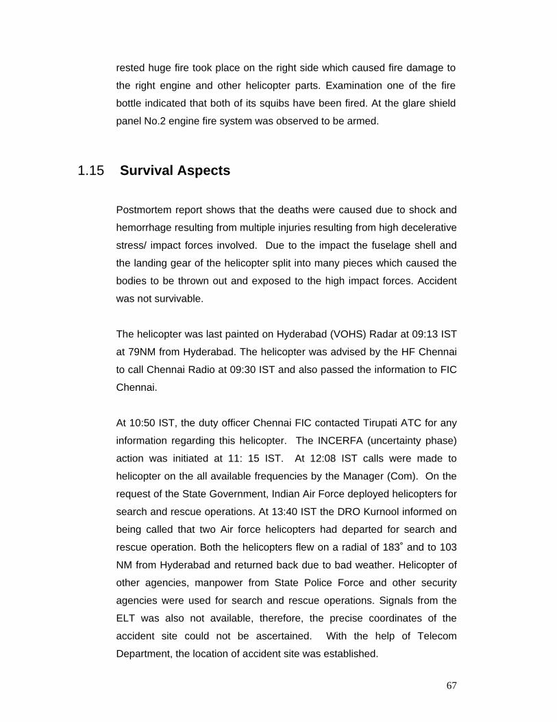
Fired Squib
Therefore fire appears to have been triggered in the baggage
compartment which houses auxiliary fuel tank. Externally it caused fire
damage soot deposit on the area of the helicopter behind it. Inside the
cabin fire traveled from aft to the forward. At the place the wreckage finally
67
rested huge fire took place on the right side which caused fire damage to
the right engine and other helicopter parts. Examination one of the fire
bottle indicated that both of its squibs have been fired. At the glare shield
panel No.2 engine fire system was observed to be armed.
1.15 Survival Aspects
Postmortem report shows that the deaths were caused due to shock and
hemorrhage resulting from multiple injuries resulting from high decelerative
stress/ impact forces involved. Due to the impact the fuselage shell and
the landing gear of the helicopter split into many pieces which caused the
bodies to be thrown out and exposed to the high impact forces. Accident
was not survivable.
The helicopter was last painted on Hyderabad (VOHS) Radar at 09:13 IST
at 79NM from Hyderabad. The helicopter was advised by the HF Chennai
to call Chennai Radio at 09:30 IST and also passed the information to FIC
Chennai.
At 10:50 IST, the duty officer Chennai FIC contacted Tirupati ATC for any
information regarding this helicopter. The INCERFA (uncertainty phase)
action was initiated at 11: 15 IST. At 12:08 IST calls were made to
helicopter on the all available frequencies by the Manager (Com). On the
request of the State Government, Indian Air Force deployed helicopters for
search and rescue operations. At 13:40 IST the DRO Kurnool informed on
being called that two Air force helicopters had departed for search and
rescue operation. Both the helicopters flew on a radial of 183˚ and to 103
NM from Hyderabad and returned back due to bad weather. Helicopter of
other agencies, manpower from State Police Force and other security
agencies were used for search and rescue operations. Signals from the
ELT was also not available, therefore, the precise coordinates of the
accident site could not be ascertained. With the help of Telecom
Department, the location of accident site was established.
68
On 3.9.2009 at 09:10 IST information was received by WSO, Hyderabad
ATC that an Air Force helicopter has sighted the wreckage and ground
parties are proceeding to the site. Finally the wreckage of helicopter was
located after more than 24 hours of search. At 12:01 IST information was
received by WSO, Hyderabad ATC confirming the death of all five
passengers. At 17:10 IST message was received by WSO, Hyderabad
ATC that three helicopters have departed from the crash site to Begumpet
with the dead bodies. At 19:20 IST search and rescue operation was
terminated by GM(Aero)-Chennai.
1.16 Tests and Research
1.16.1 Forensic Report Forensic Examination of the samples collected from the site was carried
out at Andhra Pradesh Forensic Science Laboratories, Hyderabad. In
their report, they have ruled out the presence of explosive substances,
their residues and inflammable hydrocarbons.
1.16.2 Metallurgical Examination
1.16.2.1 Metallurgical examination of No.1 Engine accessory gear box housing
and electrical harnesses of No.1 generator was carried out at Defense
Metallurgical Research Laboratory Hyderabad using Scanning Electron
Microscope (SEM). The fracture surface of larger sample revealed
globular deposits over large areas. The area clear from such deposits
predominantly revealed an intergranular fracture having secondary
intergranular cracks. The fracture surface of the smaller sample also
showed globular deposits before cleaning. After cleaning the fracture
surface revealed predominantly an intergranular fracture.
69
In order to simulate an impact loading condition, a small piece of the gear
box housing was cut and broken using impact load. On examining this
sample under SEM an essentially intergranular fracture was revealed over
the entire fracture surface. A bunch of wires from a few broken strands of
all the three generator cable were cleaned and examined under SEM. The
broken ends showed relatively brittle failure without much deformation. At
higher magnification the fractured ends of the wires revealed dimpled
rupture.
Metallographic Examination
Sections near the failed region and away from it were prepared for
metallographic examination. On etching with picral the samples revealed
equiaxed grains of magnesium solid solution and intergranular precipitates
of a second phase in both the samples.
Chemical Analysis The accessory gear box housing and the powder collected from the burnt
surface were analysed by wet chemical method and Electron Probe Micro
Analyser (EPMA). The result revealed the presence of rear earth, zinc,
zirconium and magnesium. On analyzing the surface deposit powder by
EPMA, results revealed the presence of Mg, Zn, O and C. X-Ray mapping
of the matrix and grain boundary phase showed the presence of Mg, RE,
Zr and Zn along the grain boundary.
Hardness Hardness was measured on the sample cut from accessory gear box
housing at 5 kg load and the average Vickers hardness was found to be
60 HV.
Conclusion
SEM fractography revealed intergranular fracture features. This mode of
cracking/ fracture can occur under Stress Corrosion Cracking (SCC) or
70
due to impact overload in magnesium based alloys. Since the second
phase comprising of Mg-RE-Zn along grain boundaries resists crack
propagation by SCC the fracture mode in this alloy due to SCC is
predominantly transgranular with branching. As this kind of evidences
were not observed in the present case, SCC as the cause of failure can be
ruled out.
Further to eliminate SCC as the cause of failure the material was
subjected to impact load under laboratory condition, which showed that the
material fractures in intergranular mode.
The Mg-RE-Zn phase forming along the grain boundaries is a massive
brittle phase that reduces the ductility of this alloy, although the alloy
exhibits very good strength and castability. Under the condition of impact
overload the alloy fractures in an intergranular mode as the easy path of
crack propagation is along the brittle grain boundary phase. The mode of
failure has also been confirmed by simulated laboratory test.
It is, therefore, reasonable to infer that the component had failed by impact overloading at the damaged area as evidenced by intergranular
fracture in SEM fractography. The adherence of some deposits on the
fracture surface were found to be due to burning of the portion after
breakage as it was found to contain oxides of magnesium and zinc.
The broken ends of the wires did not show any deformation which
confirmed that the failure was due to a sudden pull rather a slow tensile
pull. The ends of the wires did also not show presence of any melted and
resolidified globules ruling out the possibility of sparking leading to the
breakage cables. Hence it is inferred that the breakage of the generator
cable was due to overload at high strain rate condition as evidenced by
SEM fractography.
71
1.16.2.2 National Aeronautics Laboratory had carried out general examination of
the wreckage to establish the cause of failure. Based on the evidences
and physical examination of various items/components, it was concluded
that there was no failure in the flight control system components in air.
The failure in these components was instantaneous and would have
occurred during impact of the helicopter on ground. There were no
signatures of explosive damage on any of the components of the
helicopter. The conclusion was arrived based on physical inspection of
the wreckage and examinations carried out in the laboratory.
1.16.2.3 Tear Down Inspection of Transmission
CVR indicated that in the later part of the flight crew experienced
transmission pressure snag. To confirm snag of the transmission; possible
gear degradation teardown inspection of the transmission was carried out.
History and related Data:
Part No. : 430-040-003-109
Part Serial No. : A-55
TSN : 2949 hrs.
External Condition
The swash plate and controls were attached to the mast. The left side
input pinion had fractured from the transmission assembly due to overload
fracture of the case.
72
Left Aft View of Transmission
Examination on Dis assembly:
The mast and controls were removed from the transmission exposing the
mast lower end. The top case was removed, which exposed the planetary
carrier and ring gear. Gear teeth of on a typical planet gear, planetary ring
gear and upper teeth of the sun gear were in good condition. Teeth on the
collector gear and on the right side input pinion were in good condition.
Conclusion:
The transmission gears were in good condition. No evidence of
degradation due to lack of oil pressure which was observed. The gears in
the transmission were capable of smooth transmission of power.
73
Planetary Carriers and Gears
Upper Portion of Sun Gear
1.16.3 Temperature, Pressure Sensor/switch and Pressure regulator of Transmission
Following components were tested in M/s Pawan Hans Electrical
Instrument Lab:
a) Pressure Switch Part No.214-040-806-3, S.No.11686 was found to be
operating normally.
74
b) Pressure Regulator Part No. 206-040-088-00 – The pressure regulator
opened at approx. 40 PSI letting the oil flow from t he circumferential
outlet.
c) Fuel Oil Pressure Transmitter Part No.IPT-20RTI-1000-100G,
S.No.7113-2-969 was found to be operating normally.
d) Oil Temperature Switch Part No. 214-040-805, S.No.73168 found to be
operating normally and opened in the tolerance of 2˚ centigrade.
e) Thermal Switch Part No.102-00002, S.No. 70407 The contacts are
open circuit at 150 centigrade and closed 105 centigrade
1.16.4 Inspection of Transmission and engine Oil Cooler
The transmission and engine oil cooler was cut open to check for any
abnormality in the oil cooler. However, there was no sign of blockage, fire
and any other abnormality which could be associated with the
transmission oil cooler.
1.16.5 Boroscope Inspection of No.1 Engine
Boroscope inspection of No.1 engine was carried out by M/s Rolls Royce
representative at Hyderabad. Following are the findings:
75
• The engine had experienced obvious signs of heavy impact and fire.
• All engine mount struts had been fractured in apparent overload.
• All evidence of fire is consistent with post-impact fire. There was no
evidence of in flight fire.
• Both the N1 and N2 rotor systems were locked and could not be turned
by hand.
• The fuel system had been compromised by fire; no sample was
available.
• All engine accessories were heavily damaged by impact and fire.
• The upper and lower chip detectors were not removed.
• The engine CEFA assembly was melted by fire, exposing the filter
elements. No contamination was visible on these elements.
• The fuel nozzle was removed and inspected; it had begun to rust but was
otherwise normal.
• Boroscope inspection of the compressor revealed no obvious internal
failings of the compressor wheel. The compressor had been exposed to
fire and was sooted as far as the boroscope equipment could reach. The
compressor intake (#1 bearing support strut) had sustained minor impact
damage.
• Boroscope inspection of the combustor section (via the fuel spray nozzle
port) revealed no obvious signs of failure or combustion anomalies. The
combustor contained a significant amount of what appeared to be finely
shredded vegetative matter. There was no metal spatter or other evidence
of compressor failure.
• Boroscope inspection of the turbine section revealed no obvious signs of
damage to either the (#4 turbine wheel or nozzle, nor the #1 turbine wheel
or nozzle).
1.16.6 Download of Data from Engine Electronic Control Unit
ECU data from the No.2 engine FADEC system was downloaded at
Hyderabad by Rolls Royce representative and examined by Rolls-Royce
engineers in Indianapolis. Due to damage to the No.1 engine FADEC
76
system it was downloaded at M/s Goodrich Facility at Connecticut. The
No.2 engine FADEC was again downloaded and was functionally tested
for Standard Acceptance Testing Process, no test anomalies were
recognized during this process. Available evidences revealed both
engines appeared to be operating normally until impact. No hard faults
were recorded on either engine.
The sequence of events leading to accident is as follows:-
Time 0 to 3.6 seconds
Both engine and FADEC were operating normally. There is increase in
ambient pressure indicating drop in altitude of 500 to 850 ft. Both the
throttles are in ‘fly’ position collective pitch on No.1 engine is 32% and
No.2 at 34%. Both FADEC controlled engine in auto mode. No.1 engine
two minutes OEI event had been detected.
Time 3.6 to 8.4 seconds
Collective pitch is reduced from 24 to 18% on No.1 engine and 24 to 20%
on No.2 engine. Correspondingly there is reduction in fuel flow, engine
power, torque and an MGT. Ambient pressure climbs indicating drop of
approximately 1200 ft. on No.1 FADEC and 650 on No.2 FADEC.
Time 8.4 to 10.8 seconds Collective pitch is increased (18 to 24 % No1, and 20 to 24% on No2).
However the rotor speed continues to climb to 108%. The power turbine
speed follows rotor speed to 104% before turning back to 100%. Ambient
pressure climbs indicating drop in altitude of approximately 600 ft. on No.1
FADEC and 1100 ft. on No.2 FADEC.
77
Time 10.8 to 12.0 seconds
Both collective pitch setting was rapidly increased from 22 to 44% and
then lower to 8%. As a result the speed of the unloaded power turbine
climbs to 108% on both engines. Rotor speed continues to increase to
111% on both despite torque of 2%. Ambient pressure climbs from 13.33
to 13.52 PSI on No.1 and 13.7 to 13.75 on No.2 indicating additional drop
in altitude of approx. 400 ft. and 50 ft. respectively.
From the above as recorded by FADEC No.1 cumulatively over 12
seconds ambient pressure increased by 1.29 seconds psia indicating that
altitude decreased by approx. 2800 ft. to 2200 ft PA. This equates a
descent rate of approx. 14,000 ft./min. Similarly, FADEC No.2 indicates
corresponding increase of ambient pressure by 1.31 psia indicating that
altitude decreased by approx. 2850 ft. to 1650 ft PA. This equates to a
descent rate of approx. 237 ft./sec or 14,200 ft./min
The ECU data indicated that on No.1 engine, two minutes OEI event had
occurred. The event lasted for 14.208 seconds and was due to MGT
exceeding the two minute OEI limit of 1468ºF for more that 12 seconds
continuously. The cumulative MGT exceedance is recorded for 44.256
seconds. The data also indicates that during the event, torque exceeded
its two minute OEI limit of 102.5% for 4.224 seconds. Because the event
data is recorded in NVM and restored to RAM at ECU power-up, it is
possible that the event occurred during a previous flight. Had an MGT run
limit exceedance occurred during the final flight, it is expected that an MGT
run limit exceedance fault (MGTRLmTOut) would have been recorded in
the last engine run fault, accumulated fault and timestamped fault areas of
NVM Fault recorder. Therefore it is concluded that the exceedance
occurred during a previous flight and the exceedance fault records were
manually cleared from the accumulated and time stamped fault areas of
NVM using the maintenance terminal during the previous maintenance
action. It would have resulted in an advisory indication to the pilot,
78
displayed as a white ‘1M/OEI’ on the IIDS prior to and during the final flight.
1.16.7 Engine Tear Down Inspection Further to the boroscope inspection of No.1 engine performed by M/s Rolls
Royce representative, tear down inspection of power plant was performed at
the facilities of A.P. Government at Begumpet Airport. The engines displayed
no indications of any pre-impact anomalies or distress that would have
precluded normal engine operation prior to impact. Both the engines were
running when the impact took place. The salient observations made during
the strip examination are as follows:
Note: -All positional references are in relation to view from aft looking forward. Upstream and downstream references are in relation to gas path flow from the compressor inlet to exhaust.
SUMMARY OF FINDINGS
Both the left and right engines displayed severe impact and fire
damage.
There were no indications of any pre-impact distress or operational
dysfunction to any of the engine components examined.
No.2 engine showed more appreciable sign of circumferential rub in the
turbine section and damage to the leading edges of the compressor
vanes.
1.16.7.1 LEFT ENGINE (No.1) EXAMINATION.
i External Condition The engine was recovered in the engine housing. It exhibited impact
damage and fire damage. The compressor intake had fire damaged.
79
View from the front
a. Two compressor support struts had sustained frontal impact damage. No.1
lubrication line was intact. None of the compressor blades exhibited
impact or foreign object damage. Diffuser vent pipe in place no rupture
seen. Discharge tube was in place and no rupture seen. Main Drive Shaft
was broken. AGB housing is burnt and broken on the forward bottom right
side. N2 pickup is bent though in place. N1 pickup was in place.
b. Accessory Gear Box Top surface covered with soot and discoloration observed. Filter was
satisfactory and no pop out was observed. Breather was in place. HMU
was intact and in place and lever was free to move.
c. Exhaust Duct: Displayed moderate compressional deformation.
d. MGT harnesses were all intact. 6 &7 and No. 8 bearing lube line in place.
The spray face of the fuel spray nozzle exhibited light carbon buildup and
had begin to rust. Majority of the fuel line to FSN was consumed by fire.
The Combined Engine Filter Assembly (CEFA) had melted by fire
exposing the fuel filter element.
80
ii. DISASSEMBLY OBSERVATION
a. Combustion Chamber Liner displayed no sign of operational distress. Inlet vanes were in
satisfactory condition. No elongation or crack seen in primary, secondary,
tertiary holes. No distress, crack or metal deposit seen on the flame tube.
Combustion Chamber
b. Accessory Gear Box
Cooler shaft drive adopter shows sign of overheating and soot deposits.
The half burnt “O” ring was available on the shaft.
HMU SNO JGAMT 0539: Potentiometer burnt and charred. FADEC cable
burnt. Output line to fuel nozzle was satisfactory. Splined drive was
satisfactory. Electrical connection intact with burn marks. At the mating
surface of pump and metering unit burn mark, fusion and charring
observed. Heat shield burnt and frayed.
Starter Generator: Soot deposit seen on mounting pad. Insulation of the
electric harness was burnt and few electric harnesses were snapped and
81
showed formation of metallic bulb or deposit of molten metal at the broken
end.
Electric Harness GEN. 1
Burnt oil deposits seen inside the accessory box casing and gears. No
mechanical failure observed in the gearbox.
c. Turbine: No.2 Stage: No damage/operational distress seen on the guide vanes and
rotor blades or scoring on the shroud. Free to rotate. No cocking observed
in No 6&7 bearing. Burnt oil seen in the hub. All four thermocouples were
in satisfactory condition.
No.3 Stage: No damage/operational distress seen on the guide vanes and
rotor blades. Turbine shroud displayed light circumferential scoring from
3ºclock position to 9°clock due to radial contact with blade tips. Turbine
was free to rotate.
82
No.4 Stage: No damage/operational distress seen on the guide vanes and
rotor blades. Burning marks were seen on the tip of two blades. Aluminum
drops were seen on tip of one blade. No.8 bearing nozzle was clean
d. Centrifugal Compressor Inlet is clean except for ingestion of smoke and dust. Diffuser discharge
tubes are clean. Compressor rear was clean, no pitting or burn marks
observed.
No 2 bearing free to rotate. On outer surface soot deposit and little
charring observed
2½ bearing impression and burning observed on the inner race.
1.16.7.2 RIGHT ENGINE (No.2)
i External Condition
The engine was recovered in the engine housing. It exhibited impact and
fire damage. The compressor intake was also damaged in fire.
In the compressor, damage was observed on the leading edge of seven
blades from 12° clock position to 9° clock position which was apparently
due to ingestion of foreign objects. No.1 lubrication line was intact. Main
Driveshaft was intact. Diffuser vent pipe in place no rupture seen.
Discharge tube was in place and no rupture was seen.
a. Accessory Gear Box
Casing of Accessory gearbox was consumed in fire. Drive train had
separated. Discoloration soot deposit and white deposits were observed
on gears and shaft. Heat shield burnt and warping observed.
Starter Generator: Disintegrated
b. Exhaust Duct: Displayed moderate compressional deformation and white
deposit on the inner surface.
83
c. MGT harnesses were all intact. 6 &7 and No. 8 bearing lube line in place.
The spray face of the fuel spray nozzle was clean. Majority of the fuel line
to Fuel Spray Nozzle was consumed by fire.
ii DIS-ASSEMBLY OBSERVATION
Dis-assembled view of Engine No.2
a. Combustion Chamber Liner displayed no sign of operational distress. Inlet vanes were in
satisfactory condition. No elongation or crack seen in primary, secondary,
tertiary holes. No distress, crack or metal deposit seen on the flame tube.
b. Turbine: No.2 Stage: Blade impression seen on the turbine shroud. No damage
seen on guide vanes and rotor blades. Free to rotate. No cocking
observed in No 6&7 bearing. Burnt oil seen in the hub. All four
thermocouples were in satisfactory condition.
No.3 Stage: No damage/operational distress seen on the guide vanes and
The officials were not able to reach to the site of accident as the Air Force
helicopters were engaged in recovery of the bodies and transporting it to
Kurnool. The District Magistrate was requested to get the investigation
team flown through a Air Force Helicopter to the accident site however no
helicopter could be made available.
The police team from the district had reached the spot and recovered the
CVR and few other documents which were subsequently handed over to
CB-CID, State of AP. These documents got further transferred to CBI.
The CBI was also investigating the helicopter accident simultaneously, had
many queries on the technical issues for their investigation and the same
could not be answered as the technical investigation was at initial stage.
91
The multiple agencies carrying out investigation definitely does not augur
well as the investigation for the technical aspect requires thorough study of
various shop level investigation of various components and items of
equipment.
• Release of Information to Media:
During the course of investigation it was observed that many media
agencies and the aggrieved families wanted to seek the information on the
progress of investigation. As the matter of international practice adopted
all over the developed nation it is essential to brief the stakeholder by
giving a press release or brief on the progress of accident investigation.
However, in the absence of directives on the issue to the Committee such
briefings were not conducted.
1.18 Additional information Nil
1.19 Useful and Effective Investigation Techniques Nil
2.0 ANALYSIS
2.1 Airworthiness of Helicopter
2.1.1 Maintenance of Helicopter The Certificate of Airworthiness of the helicopter was current and valid.
Periodicity of all scheduled maintenance task were maintained. As per the
available records no snag was reported during the C of A inspection. The
organisation did not maintain any snag register to allow analysis of the
defects.
92
Para 08,Section II, Chapter 2 of QC cum Assurance Manual requires that” a
separate ‘Snag Register’ for each helicopter shall be maintained where all
defects and rectification actions as recorded in flight report Book &
additional work sheet shall be reproduced”
The action of the maintenance organisation was in violation of the procedure
specified in the Quality Control manual.
Review of journey log book did not indicate repetitive snags. Power
assurance check was carried out regularly and engine parameters were
being recorded. Review of power assurance check did not indicate any
abnormality. Journey logbook only up to 7th August 2009 was provided.
Engine S/N: CAE-844104 was removed from helicopter on 01/11/2007 from
No. 2 position at 2160:05 hrs and installed on 30/05/2009 at No: 1 position
at 2160:05 hrs after repair and modification at the manufacturer facility at
Oakland. Reason for removal was not recorded in the logbook. There is no
preservation/de-preservation entry for the storage period. Reason for
removal of any other component is not recorded. This indicates casual
attitude of the maintenance personnel.
As per the Quality Control cum Assurance manual of the organisation, “The
QA manager should be free from all certification duties so that his decisions
are not influenced by production/certification consideration”. In this
organisation only one AME was performing the job of certifying staff, QCM
and Quality assurance personnel. The organisation had once engaged
outside personnel for the audit. The report submitted by him did not mention
any deficiency despite many deficiencies as mentioned above. Therefore
quality assurance function of the organisation was not performed as per the
laid down practices/ directives.
2.1.2 Download of FADEC Data The data from the ECU was downloaded at M/s Goodrich facilities, USA.
ECU data indicated that the engine No 1 was operated over the MGT run
limit of 1435 F for 44.256 seconds. The peak MGT recorded during the
93
exceedance time is 1487.8 F. because the exceedance time is cumulative, it
is possible that there was more than one exceedance event, although an
event must persist for more than 12 seconds before the exceedance time
i.e., including the 12 second is recorded. Had an MGT run limit exceedance
occurred during the final flight, it is expected that an MGT run limit
exceedance fault (MGTRLmTOut) would have been recorded in the last
engine run fault, accumulated fault and timestamped fault areas of NVM
Fault recorder. Therefore it is concluded that the exceedance occurred
during a previous flight and the exceedance fault records were manually
cleared from the accumulated and time stamped fault areas of NVM using
the maintenance terminal during the previous maintenance action.
A ‘Two minutes OEI’ event had been detected on No.1 engine. The event
lasted for 14.208 seconds and was due to MGT exceeding the two minute
OEI limit of 1468ºF (for more than 12 seconds continuously). The
cumulative MGT exceedance is recorded for 44.256 seconds. The data also
indicates that during the event, torque exceeded its two minute OEI limit of
102.5% for 4.224 seconds. Because the event data is recorded in NVM and
restored to RAM at ECU power-up, it is possible that the event occurred
during a previous flight.
However the exceedance did not have the timestamped information.
Therefore it was not known that at what stage the exceedance had
occurred. If exceedance is not erased after necessary rectification
action/inspection, it continues to be indicated on the IIDS screen. M/s
Goodrich has opined that “it would have resulted in an advisory indication to the pilot, displayed as a white ‘1 M/OEI’ on the IIDS prior to and during the final flight.” As per section 3 emergency / malfunctions
of document BHT-430-FM-1 “the maintenance action is required prior to
next flight, if this advisory is indicated”. This implies that before operation of
flight the advisory should have been seen by the AME during the preflight
check and also by the pilot before undertaking the flight.
94
The AME has stated that at no stage this exceedance was seen on IIDS
either during the preflight inspection on 02.09.2009 or before it. The engine
was installed on this helicopter after rectification action at the manufacturer
facility and they returned the engine after clearing all the defects. Further
150hrs/3 month inspection schedule was carried out on 28.08.2009. During
that inspection snag/exceedance if any had to be cleared. Thereafter the
helicopter flew on 1.09.2009. The helicopter on 02.09.2009 was released
with this exceedance.
The organisation has maintained neither the soft copy nor the printout of
ECU downloads of the exceedance data after March 2007. However,
organisation has been maintaining a register for recording the exceedances.
All the exceedances recorded were examined and only exceedance of the
torque was observed on No.1 engine in June 2009. However none of
recorded exceedance matched the exceedance observed during the post
accident ECU down load. Therefore the exceedance had occurred during
the training/positioning flight on 1.09.2009 / 2.09.2009. This is lapse on the
part of the crew and on the part of AME that with advisory of No.1 OEI, AME
released the helicopter for the flight and the crew operated the flight.
No written instruction exists for departure from the practice of retaining soft
copy. The reason advanced by the AME was poor state of the laptop and
the past practices. As per the manufacturer requirements, any laptop
meeting their specification for the hardware can be used and the software is
available online. It is apparent that replacement action for the laptop and
software was delayed due to unsettled organisation and lack of knowledge
in handling the laptop for downloading the data and removing the
exceedances after the rectification action.
2.1.3 Serviceability of Engine Examination of the wreckage revealed that there was soot deposit/fire
damage on the left side of helicopter aft of the baggage compartment. Soot
deposit was also seen on the stones and the trees. The passengers sitting
95
in the left portion of the helicopter also had fire injuries in the back of the
body. Also there was fire at the place where helicopter wreckage finally
rested. There was substantial fire due to which accessory gear box of the
right engine was burned /destroyed in the fire. Other helicopter parts at the
main wreckage location also sustained fire damage. Further the glare shield
panel indicated No.2 engine in manual mode and No.2 fire system in armed
position. One of the fire extinguishers which were intact was dismantled and
on inspection it was revealed that it had been fired. CVR readout of the last
phase also suggested that the helicopter was losing height and same was
corroborated by the ECU readout which indicated a very high rate of
descent during last 14 seconds. Therefore strip investigation of the engines
were carried out to determine there serviceability. ECU readout of both the
FADECs indicated in the pre-incidence phase the engine parameters viz.
Torque, MGT, Power turbine RPM to be normal. This indicated that the
performance of both the engines before the accident was satisfactory.
The boroscope inspection of the No.1 engine was carried out by the expert
from the manufacturer and also tear down inspection of both the engines
were carried out. These inspections did not reveal of any abnormality in the
compressor, turbine and combustion chambers. This indicates that there
was no engine fire or any engine related abnormality. Visual inspection of
the electric harness of the No.1 generator revealed that few of the cut wires
had globules/ molten metal deposit at the cut end. To confirm whether any
short circuit/arcing had taken place or not, the harnesses were subjected to
metallurgical examination. Metallurgical examination revealed that the failure
was due to high tensile stress and did not reveal of the electrical fire. It
indicates that the generator was working when the electric harness
snapped. Further the No.1 generator was also examined. It indicated
electrical overheating and not fire. Thus it indicates that both the engines
were producing power before the impact and there was no engine failure.
2.1.4 Serviceability of Transmission Gear Box As per the CVR readout at 09:21:07 IST the crew encountered the snag of
transmission oil. For taking appropriate action they reviewed the checklist
96
and the flight manual for transmission oil pressure. Therefore to identify any
failure which led to snag encountered by the crew the teardown inspection
of the rotor transmission gearbox was carried out. The transmission gears
were found to be in good condition. No evidence of degradation due to lack
of oil pressure was observed. No sign of overheating was observed. The
gears in the transmission were capable of smooth transmission of power.
Further to identify the reported snag transmission oil pressure and
temperature sensors; pressure and temperature switches and pressure
regulator were subjected to the bench check at the M/s PHHL facility in
Mumbai and manufacturers facility in Texas, USA. However no discrepancy
was noticed. Therefore the cause of the observed snag could not be
established. The crew also did not collaborate with other identifications of
emergency i.e. caution warning light as evident from CVR readout.
2.1.5 As per CAR Section 2 Series F Part V, the Certificate of Airworthiness of an
aircraft shall be deemed to be suspended when an aircraft ceases or fails
to conform with condition stipulated in the Type Certificate or C of A,
airworthiness requirements in respect of operation, maintenance,
modification, repair, replacement, overhaul, process or inspection applicable
to that aircraft, or
2.1 is modified or repaired otherwise than in accordance with approved
procedure, or
2.2 suffers major/substantial damage (which requires replacement or
extensive repair of any major component), or
2.3 develop a major defect which would affect the safety of the aircraft or its
occupants in subsequent flights.
It appears from the available evidences that on 02.09.2009 the helicopter
was released with the exceedance of MGT and use of OEI on no.1 engine.
Thus the helicopter was probably not airworthy when it was released for
flight on 02.09.2009 even though it was not a contributory factor to the
accident.
97
2.1.6 Why ELT failed to transmit?
It was established that ELT was installed on the helicopter and was
serviceable. However, ELT had 121.5 MHZ and 243 MHZ as operating
frequencies. As per CAR of Section 2, Series O Part V and ICAO’s
recommendations in Annex 10, all ELT must have three frequencies
including 406 MHZ as operating frequencies. This requirement is effective
from 01 January 2005, however, was not implemented by APACL on this
helicopter. This issue needs to be addressed by the Regulatory Authority.
Unless signals are transmitted at 406 MHZ, it is not possible to initiate
satellite based search operation to pin point the location of the accident,
aircraft/helicopter. The ELT got detached and had fire damage. Even if it
had transmitted the signals, being at location out of VHF coverage, ATC
would not have picked up the distress call.
In view of failure of ELT to transmit distress signals in a number of previous
accidents, installation and suitability of ELT location needs immediate
examination. An alternate system of flight following needs to be examined
and installed for prompt search and rescue in case of accident.
2.2 Weather Local forecast for VOHY/VOHS and 100nm around valid 02/03:30 IST to
02/11:30 IST indicated the surface wind to be 290/10 KT. A reduction of
visibility to 3000 m in moderate rain/drizzle or haze till 08:30 IST. Possible
formation of isolated Towering Cumulus or CB clouds with base at 750 meters
and top height 9000 meters was also forecast. Moderate to severe turbulence
and icing in CB was forecast during the period. Warning for light aircraft
“WIND SPEED MAY REACH 20 KT IN GUST FROM 270˚ ” was also
appended to the local forecast.
98
In the TAF for Chittoor, Ongole and Krishnapatnam, the possible formation of
CB clouds and temporary reduction in visibility from 6000 meters to 3000
meters in thunderstorm and light rain was forecast, from 07:30 to 14:30 IST.
Synoptic observations for the Kurnool for the period for 08:30 IST and 11:30
IST was slight rain, overcast sky with 3 oktas low clouds of base height 600-
999 m.
Satellite imagery of 09:00 IST indicated a sudden increase in convection over
the site and also the accident site area to be fully covered by convective cloud
cluster. The maximum increase in convection was over southwest sector.
Satellite imagery of 09:30 IST indicated accident site was fully covered by
convective cloud cluster and there was further increase in aerial extension of
the convective cloud cluster.
From the observations of 08:30 IST on 2nd September, rain/thunderstorms
were observed at most places of Telangana and Kurnool reported 4.5 cm of
rain. There were no synoptic systems present exactly over the accident
region, however, the southwest monsoon was active in the neighbouring
subdivisions, like Konkan & Goa, Vidarbha, coastal Karnataka, and Kerala on
2nd September 2009.
As per the lightning data, the storm center was located in the path of
helicopter and lightning activity was reported in the area comprising the
accident site at about 09:00 hrs IST and 09:35 IST.
As per the residents of area near the accident site, it was raining heavily in the
area and the visibility was also poor.
As per the CVR readout, they were encountering clouds almost from the
beginning of flight. At 9:10:50 IST and at a distance of 64 nm the helicopter
entered the clouds and accordingly the PIC instructed the co-pilot to keep
hand on the collective so as to reduce it, as down draught may lead to
exceedance of the torque. The Helicopter weather radar was painting red
99
which shows heavy rain or CB clouds. At 9:13:17 IST due weather, they
decided to be slightly on the left of the track. Although they cleared the red
zone as painted on their weather radar, however they continued to fly through
the clouds. At 9:16:31 IST they observed that clouds were more on the right of
the track and quantum of clouds were increasing. They decided that after
crossing Krishna River they would turn left. At 09:20:11 IST they reported
abeam Kurnool but were still in clouds. At 09:20:22 IST, they were at 86 nm
and probably crossing Krishna River. From 09:27:24 IST there were repeated
callouts from co-pilot to “Go Around” thus indicating of some problem. The
Engine Control Unit (ECU) readout shows that during the last 14 seconds the
rate of descent was in excess of ten thousand feet/minute indicating that
helicopter during this period when the co-pilot was giving callouts for go
around was encountering very high rate of descent. During this period as per
the ECU readout there was exceedance of Main rotor RPM, power turbine
RPM with simultaneous drop in the collective.
From the above it is apparent that they were flying through the clouds and
anticipated up draught/down draught. Finally at the accident site they
experienced sudden sink. At that point of time (09:30 IST) as per the satellite
imagery, accident site was fully covered by convective cloud cluster and there
was further increase in aerial extension of the convective clouds accompanied
with heavy rain and lightning.
As per Text on Aviation Meteorology by K.M. Wickson, Airlife Publishing Ltd.
England, “In thunderstorms or CB substantial shafts of air may be
encountered, with no warning, which can be moving either vertically up or
down. Such shafts may be virtually side by side, and the shear will then be
very marked and violent”. It further states that “Cumulonimbus-Thunderstorms
mature stage is reached when there is precipitation. By this time, the ice
crystals have formed together with large concentrations of water droplets,
resulting in precipitation. This will cause down currents which may reach
speeds of 2000 ft to 3000 ft per minute. The up currents increasing at this
stage to some 6000 ft/minute. These vertical movements cause turbulence
100
inside the cloud. The cloud top will be close to tropopause height and in low
latitudes this can be in excess of 50,000 ft”.
Thus it is apparent that at the accident site severe down draught existed and
was encountered by the helicopter. This is corroborated by high rate of sink
encountered by the helicopter and heavy precipitation in form of heavy rain.
2.3 Conduct of the Flight
2.3.1 Crew Qualification and proficiency Both the crew held valid license and were qualified on type. Their ratings
were current. The PIC had a total flying experience of 6204:30 hrs out of
which 350:40 Hrs were on Bell 430 helicopter.
• Air safety Circular 2 of 1981, Para 3.2 regarding carriage of VIPs in
private/State Government owned aircraft states :-
3.3.2When operation is by Helicopter:
3.3.2.1 The Pilot –in –Command should be in possession of a
current commercial Helicopter Pilots Licence.
3.3.2.2 The pilot should have a minimum of 500 hrs.
experience as Pilot-in-command on Helicopters, including 10
hrs. of night flying and not less than 75 hrs., as Pilot-in-
command, on type of helicopter t o be flown.
3.3.2.3 The pilot should have a minimum of 30 hrs.
experience as PIC on Helicopters in the last 6 months
including 5 hrs. on the type helicopter in the last 30 days,
immediately preceding the date of intended flight.
NOTES:
(ii) Whenever practicable, an additional pilot may be carried
possessing current CHPL and IR rating.
101
Both the crew met all the requirements of the above air safety circulars on
the date of the flight. However following were the discrepancies regarding
license of PIC:-
For the Endorsement on Bell 430 helicopters only one instrument
rating test was carried out against the requirement of two Instrument
rating tests with two different examiners for as per Schedule 2,
Section P, Subpara E of Aircraft Rules 1937.
Flying hours during training sorties have been reflected as PIC flying
in the personal log book whereas it should be in Training Column.
The instructor who conducted the night flying and instrument flying
training has also undertaken night skill test and instrument rating test
as well. Only day skill test by the training instructor was carried out
with FOI (H) DGCA on board as observer.
This indicates lack of knowledge/disregards to the rules by the PIC and
supervisory staff. The above two discrepancies also went unnoticed
during the check by the then Instructor/examiner and endorsement on
his licence by the licensing authority.
• CAR Section 7 Series B, Part XIV, Para 2.2b (ii) requires
Simulator Training for critical emergencies: At least 5 hours of mandatory practice of critical emergencies in
simulator such as engine failure, system failure, tail rotor failure etc.
which cannot be practiced or simulated in actual flying shall be carried
out by a pilot on specific type of flight simulator once in two years. The
satisfactory simulator test report shall be submitted to the Directorate
General of Civil Aviation along with application for renewal of pilot
licence.
102
Recurrent simulator training became due for PIC in the month of June
2009 on completion of two years from the date of endorsement viz.
5.06.2007 and was not carried out. This is non-compliance of Civil Aviation
Requirements.
2.3.2 Flight Planning Crew obtained the Meteorological briefing for the route VOHY-Chittoor-
Ankul Pattru (Nellore Dist)-Ongole from Aviation Meteorological Services
(AMS) Begumpet at 06:30 IST on 2nd September, 2009. The pilot was
briefed about the presence of CB clouds tops reaching 12 km and showed
the 05:30 IST imagery and satellite bulletin based on 01.09.2009 / 17:30
IST. In the local forecast and for 100 nm around VOHY/VOHS valid
02/03:30 IST to 02/11:30 IST, the surface wind was forecast to be 290/10
KT. A reduction of visibility to 3000 m in moderate rain/drizzle or haze was
forecast till 08:30 IST. Possible formation of isolated Towering Cumulus or
CB clouds with base at 750 meter and top height 9000 meter was also
forecast. Moderate to severe turbulence and icing in CB was forecast
during the period. In the TAF for Chittoor, Ongole and Krishnapatnam, the
possible formation of CB clouds and temporary reduction in visibility from
6000 meter to 3000 meter in thunderstorm and light rain was forecasted
from 07:30 to 14:30 IST. Thus the crew was aware of the existence of the
CB clouds with top reaching 12KM, in the route to be flown. However they
did not review the subsequent satellite pictures before the preparation of
departure at 08.29 IST. Subsequent satellite pictures revealed as follows:-
• 06:30 IST: Increase in convection and aerial extension, specially
towards southeastern sector of the accident site was observed.
• 07:00 IST: Further slight increase in convection and aerial
extension in southeast sector of the accident site is observed.
103
• 08:00 IST: The convection in the southeast sector nearer to the
accident site area decreased. In the rest of the areas/sectors
cloud clusters remain more or less same.
CAR section 4 Series E Part I Para 3.6.2.4 states that
Weather deterioration below the VMC. When it becomes evident that flight
in VMC in accordance with its current flight plan will not be practicable, a
VFR flight operated as a controlled flight shall:
a) Request an amended clearance enabling the aircraft to continue in
VMC to destination or to an alternative aerodrome, or to leave the
airspace within which an ATC clearance is required; or
b) If no clearance in accordance with a) can be obtained, continue to
operate in VMC and notify the appropriate ATC unit of the action
being taken either to leave the airspace concerned or to land at the
nearest suitable aerodrome; or
c) If operated within a control zone, request authorization to operate as
a special VFR flight; or
d) Request clearance to operate in accordance with the instrument flight
rules.
Crew was aware of the poor weather conditions on the route and before
departure did not again review the weather situation. They choose to fly in
Instrument meteorological conditions whereas the flight was to be
conducted as per the visual flight rules. As seen from the CVR readout
they were encountering clouds almost from the beginning. At 9:10:50 IST
and at a distance of 64 nm the helicopter entered the clouds.
Subsequently also they were flying in the clouds. At this stage they should have decided either to divert to nearby location or return back to Hyderabad (sufficient fuel was available for the same).
104
Accidents that occurs in reduced visibility conditions after a pilot has
attempted VFR flight into IMC are much more likely to be fatal than
accidents that occur in Visual Meteorological Conditions (VMC) for various
reasons which also includes spatial disorientation and getting into unusual
altitude. During past three years approximately half of helicopter accidents
in India occurred in IMC and all such accidents have been fatal. None of
the pilots in these fatal accidents in those conditions had activated an IFR
flight plan.
2.3.3 Adherence to Procedures Crew copied all the instructions given by the Air traffic control. However at
09:03:20 IST approach asked helicopter to “Report in contact with Chennai
Control 118.9 alternate Chennai Radio.” There was confusion among the
crew regarding the Chennai control VHF frequency. Although they finally
verified it with Hyderabad control.
At 09:21:07 IST they encountered the snag of transmission oil. The co-
pilot was bestowed with the task of locating the procedure in emergency
checklist for the transmission pressure fault. The co-pilot reviewed the
checklist and flight manual but was not able to locate the emergency
procedure in the checklist appropriate for the snag encountered. Thus
almost six minutes of the vital time was consumed in locating the
emergency procedure in order to take appropriate actions and both pilots
were so much engrossed in it that they lost situational awareness.
2.3.4 Spatial Disorientation Reduced visibility conditions, dark night VMC, or combining VMC & IMC
also greatly increase the risk of spatial disorientation. Spatial disorientation
occurs when a pilot develops an incorrect perception of aircraft attitude,
altitude or motion relative to the Earth’s surface. It results when a pilot’s
normal visual cues to aircraft attitude are inaccurate, unavailable or
105
inadequately monitored and the pilot, instead, relies on other cues to
aircraft attitude that may be misleading.
These cues are provided by the motion-sensing vestibular organs in each
inner ear. The sensory organs of the inner ear detect angular
accelerations in the pitch, yaw and roll axes, as well as gravity and linear
accelerations. The vestibular system provides useful sensory information
under conditions of self-locomotion on the ground but provides misleading
sensations in the flight environment. Vestibular sensations are easily
ignored when pilots have a clear view of the horizon, but they become
compelling illusions when external visual references are not available.
Instrument-rated pilots are taught to ignore misleading vestibular
sensations in favour of the visual cues from flight instrumentation when
operating in IMC. However, even experienced, instrument-rated pilots can
experience episodes of spatial disorientation in reduced visibility
conditions. Situational risk factors for spatial disorientation include false
surface planes created by sloping clouds or terrain, transitions between
VMC and IMC that require the shifting of visual attention between external
visual references and cockpit flight instruments, sustained turns and high
workload. Spatially disoriented pilots are at risk of making inappropriate
control inputs that can result in loss of aircraft control.
The aircraft was flying through the clouds and there is great possibility of
spatial disorientation. During last few minutes of the flight they had
encountered a technical snag and they got engrossed in it. These two
factors may have lead to loss of situational awareness. Therefore when
the helicopter entered areas of high convective activity and the down
draught was encountered there was loss of control and helicopter
impacted the ground.
106
2.4 Management Issues and System of Maintenance & Operation
On 31.03.2006 the Government of Andhra Pradesh promoted the A.P.
Aviation Corporation Limited (a Public Limited company) with objectives of
developing aviation sector in Andhra Pradesh by setting of training
academy, acquiring aircraft and helicopters to serve the commitments of
various departments of the state government and private parties.
Accordingly it appointed full time Managing Director. However during this
period the managing director was changed three times and no system had
been evolved for coordinated working of the organisation.
The organisation changed its name to APACL. However it continues to
hold organisation approval in the name The Aviation Division, Helicopter
Wing (GAD). It is holding approval in Category “C”. The approval of the
organisation is valid up to 31.12.2009. As per the QC cum Assurance
Manual, Maintenance organisation will be headed by Quality Control
Manager assisted by Deputy QCM and AME. .The Organisation entered in
to contract with M/s OSS management services to provide maintenance
for the Bell 430 helicopter along with AW-139 helicopter. After the contract
materialized, M/s OSS expressed its inability to take care of the
maintenance of Bell 430 helicopter. Apparently no careful assessment of
service provider was carried out before entering into the contract.
Thereafter the organisation partially revived its maintenance setup for the
Bell 430 Helicopter. Prior to the contract the Helicopter wing had three
AMEs, and the supporting staff. However post contract it was left with only
one AME who also performed the duties of the Dy. Quality Control
Manager (QCM). There was no approved QCM. This put all the
responsibilities on the AME and his working was not supervised / cross-
checked for any deviation from the standard maintenance practices.
The operation wing is headed by Chief Pilot/Pilot Coordinator/Chief
operating officer. For the operation of the Bell 430 one pilot was taken
107
under contract from M/s OSS Management services. Earlier the other two
pilots were in the employment of the State Government on deputation
basis from the Indian Air Force. Though at all time organisation had
licensed crew, however no attempt was made to revise the operation
manual of the organisation in line with new Civil Aviation Requirements
and the changes in the operational policy of the organisation. The
operations manual was made in 2004 and never revised thereafter.
Organisation has not prescribed any minimum flying experience
requirements in the operation manual before permitting a newly endorsed
crew on Bell 430 helicopter to fly as PIC. Records reveal that organization
did not encourage its pilots to undergo recurrent simulator training. Many
of the reportable incidents / snags were not reported to regulatory
authorities.
Record reveals that earlier both the pilots on deputation from Indian Air
Force were engaged in the act of one up manship and despite the adverse
entries, were able to prolong their stay in the organisation beyond the
permitted deputation period. They were able to influence the decision
making process even at the highest level in the State. They were also
involved in various procurements and also like helicopter procurements
without adequate knowledge about the subject. Even selection of AMEs
for the training on new helicopter was not appropriate as the AMEs under
state were overlooked.
This did not promote a healthy culture in the organisation and indicates
lack of involvement and poor knowledge of personnel in-charge of State
Aviation set up.
2.5 What was the Source of Fire and how did it Start? Soot deposit/fire damage was observed on the left side aft of left wing. The
fire damage/soot deposit followed the air pattern. The soot deposit was not
in the upward direction. These parts had separated sequentially along the
direction of motion before the helicopter wreckage finally came to rest.
Fuselage portion aft of the baggage compartment had severe burns and
108
warping of the skin. Blistering of the paint on the leading edge was
observed on one of the blades of the tail rotor. Bodies of the passengers
which were thrown out also had fire injuries on the back.
The auxiliary fuel tank was found disintegrated and burnt. Fire damage
was also observed on the aft spar of the central tank. Baggage
compartment houses auxiliary fuel tank. Externally the fire damage soot
deposit has been caused on left side on the area of the helicopter behind
it. Inside the cabin fire traveled from aft to the forward. At the place where
the wreckage finally rested, huge fire took place on the right side which
caused fire damage to the right engine and other helicopter parts.
Examination of one of the fire bottle indicated that both of its squibs have
been fired. At the glare shield panel No.2 engine fire system was observed
to be armed and No.2 engine was observed to be in manual mode.
However, there were no signs of fire during the flight like metal spattering
on the surface along the flight direction or brooming, same is corroborated
by the intensity of fire.
Due to the fuel consumption pattern the auxiliary fuel tank was first to be
emptied. Therefore it may have been containing fuel vapours. Due to the
impact, the fuel tank might have got damaged leading to the release of the
fuel vapours which might have caught fire.
This indicates the fire was triggered either during impact with the trees or
after the first impact with the ground from the baggage compartment. In-
flight fire can safely be ruled out.
2.6 Was any explosive device detonated? Wreckage examination was carried out at the site of the accident to look
out for evidence to determine if any explosion had taken place on board at
the accident flight. Wreckage did not reveal damage due to splinters nor
the splinters were observed. Curling of metal on edges of broken parts
was absent. No damage due to impact of high pressure gases was
109
observed. Seat cushion were recovered and examined in details to find
out if there were embedded splinters or associated damages. However,
nothing was observed.
Post mortem report has not recorded any impact of/embedded splinters in
soft tissues of dead bodies nor there is evidence of affect of high pressure
waves on lungs, etc.
Opinion on the issue was taken from NAL, Bangalore who also ruled out
the possibility of any explosive material in the wreckage.
2.7 Sequence of Events On 02.09.2009 Andhra Pradesh Government Bell 430 Helicopter VT-APG
was to operate a flight from Begumpet Airport in Hyderabad to Chittoor for
the commitment of the Hon’ble Chief Minister. There were five persons on
board which consisted two crew members, Hon’ble Chief Minister and a
two member team accompanying him.
Flight plan was filed with the air traffic control at Begumpet airport. As per
the flight plan, helicopter was to fly direct to Chittoor at altitude 5500 ft.
ETA / ETD Chittoor as 09:45 IST/12:00 IST. From Chittoor the helicopter
was to proceed to Ankulpattur (ETA/ETD: 12:40/16:00 IST) and finally,
Ongole (ETA 16:45 IST). The flight was to be conducted under visual
flight rules (VFR). However, Instrument Meteorological Conditions (IMC)
prevailed at that level enroute and near the accident site.
The helicopter was positioned at the VIP departure apron. After the
positioning, no snag was reported by the crew. Crew obtained ATC and
met briefing at 06:30 IST. During the met briefing they were shown the
synoptic charts, satellite picture of 05:30 IST and provided with met folder.
As per the met briefing CB cells with height up to 12 km were present on
the route to be flown. The crew did not obtain any subsequent update of
the weather. The movement was coordinated with Chennai FIC (FIC No.
0033 and ADC No. C523).
110
The helicopter took off from Begumpet Airport RWY 27 at 08:38 IST.
Helicopter was given direct clearance to destination Chittoor at enroute
altitude 5500 ft. It was cleared to take-off from RWY-27, climb on RWY
heading to 4600 feet and further in coordination with approach radar. At
08:38:50 IST helicopter was transferred to the Hyderabad approach and it
established contact with approach radar at Hyderabad. Approach Radar
gave it clearance for climb to 5600 ft. and after reaching 5600 ft. to turn left
and set course to Hyderabad (VOHS) due to traffic. At 08:42:16 IST
helicopter was at a radial of 172˚ from HHY distance 25.6 nm and
requested to proceed to Chittoor on course 170˚ and gave ETA Chittor as
10:30 IST. Same was approved by approach Control. At 08:39:41 IST,
Approach asked “Confirm destination is Chittoor on Radial 172˚ ”.
Helicopter requested that if they could maintain the present course. ATC
asked “Report Establish Radial 172˚ from HHY” which was affirmed by the
helicopter.
At 09:03:20 IST, it reported 46 miles maintaining 5600 ft. It was asked to
descent to 5500 at 50 miles. At around 09:02 IST the helicopter contacted
Chennai on HF frequency 6655 KHZ and relayed its position along with
estimated time of arrival 10:30 IST at Chittoor. HF Chennai advised the
helicopter to report at 09:30 IST. At 09:07:46 IST and distance of 55 NM
from VOHY as per CVR readout there was a callout “altitude 5500, speed
120, ground speed 144, 83” indicating that helicopter was maintaining a
speed of 120 kts and 83% collective. It was encountering clouds from the
beginning. At 9:10:50 IST and at a distance of 64 nm the helicopter
entered the clouds and accordingly the PIC instructed the co-pilot to keep
hand on the collective so as to reduce it, as draughts may lead to
exceedance of the torque. As per CVR readout helicopter weather radar
was painting red. Last radio contact with Approach Hyderabad was made
at 09:12:52 IST and that was the last contact the helicopter had with any
ATS units during its flight. The helicopter painted on the radar screen of
approach radar Hyderabad up to 9:13 IST and at distance of 79.2 nm from
VOHS Airport. At 9:13:17 IST due to weather, they decided to be slightly
111
on the left of the track. Although they cleared the red zone as painted on
their weather radar, however they continued to fly through the clouds. Till
the helicopter painted on the radar screen of approach control, it was
maintaining an altitude of 5500 ft and ground speed of around 140 kts. At
09:18 IST there was a call out that both the VORs have gone i.e. the
helicopter was out of range from any of the VORs and would be navigating
based on the GPS and visual references. At 09:20:11 IST as per CVR
they reported abeam Kurnool whereas they were slightly short of abeam
Kurnool and were still in clouds. Despite being constantly in clouds they never thought it fit to turn back to Hyderabad or divert. At
09:20:22 IST, they were at 86 nm and had crossed Krishna River. At this
stage they were hopeful of some improvement in the weather ahead. At
09:20:46 IST there was a callout to reduce the speed. Subsequently there
was inter-crew talk that whether any thing will happen below 40kts.
At 09:21:07 IST they encountered the snag of transmission oil. Thereafter
they got engaged in finding out the procedure in the checklist for the
transmission oil pressure but were not able to find it. At 09:27: 25 IST
there was a callout regarding the Autopilot. Probably it had tripped and
was re-engaged. The autopilot would trip if the speed falls below 50 kts.
Thus it appears they had reduced the speed to 40 kts. They were flying in
Instrument metrological condition. The snag of transmission oil occupied
their attention till the helicopter impacted the ground and apparently they
lost focus of weather conditions. From 09:27:24 IST there were repeated
callouts from co-pilot to “Go Around” thereby indicating of some problem
might be close vicinity of hill feature. The Engine Control Unit (ECU)
readout shows that during the last 14 seconds the rate of descent was
probably in excess of ten thousand feet/minute indicating that helicopter
during this period when the co-pilot was giving callouts for go around was
encountering very high rate of descent. During this period as per the ECU
readout there was exceedance of Main rotor RPM, power turbine RPM
with simultaneous drop in the torque. This is consistent with a rapid
lowering of collective. As mentioned in Para 2.2 apparently a severe
downdraught existed and was encountered by the helicopter at the
112
accident site which caused sudden loss of height of the helicopter and it
impacted the hills. This is corroborated by the reading of (-) 3500 ft/min on
vertical speed indicator and speed of more than 150 kts on the airspeed
indicator. No procedure has been prescribed by M/s Bell helicopters to
negotiate the severe down draught or the flight through turbulence. CAA,
UK recommends following action when caught in a down draught.
“Widely varying conditions make it difficult to detail specific actions
to take if the aircraft encounters a powerful down draught. In general,
however, the following action should be taken: -
(a) Apply full power.
(b) Fly at best ROC/angle of climb speed depending upon the
proximity to obstruction.
(c) Turn away from the feature causing the down-drought,
while selecting a downhill route towards a clear area.
(d) Closely monitor IAS, but disregard high ground speed.
(e) Regain height in the ascending air on lifting slope.
The down-draught will reduce in severity somewhere in the
valley bottom. The following actions should be taken in case the
aircraft is likely to be forced into ground.
(a) Maintain full power and climbing speed.
(b) Turn into wind.
(c) Jettison load, if possible.
(d) Choose a landing site, which is as flat as possible — if
the ground is sloping, head up the slope if possible.
As far as possible a touchdown should be avoided and an escape
route should be followed away from further down-droughts.”
113
Inspection of the wreckage site revealed that helicopter had turned left of
its flight path by 90 degrees before impacting the hill. At 9:16:31 IST they
observed that clouds were more on the right of the track and quantum of
clouds were increasing. They decided that after crossing Krishna River
they would turn to the left. It appears that they turned left as a part of
procedure to get out of the severe downdraught or while they were turning
left as decided, they encountered the down draught. However there is no
call out for turning left and damage pattern of the helicopter suggests that
the helicopter impacted the ground in severe left bank. Thus it is apparent
that the helicopter turned left as part of procedure to get out of the down
draught. However the loss of height was so rapid that it was forced into
ground.
2.8 Search and Rescue- was the Operation Coordinated ? The Search and Rescue Service in India is organized by the Airports
Authority of India in collaboration with the Ministry of Defence, local
administrative setup, Indian Air force and other agencies who have means
to help in search and rescue operation. Since the helicopter was in the FIR
boundary of Chennai FIC. Therefore it was the responsibility of the RCC
Chennai to initiate different phases which constitute this operation. The
helicopter was advised by the HF controller to call Chennai Radio at 09:30
IST and also passed the information to Chennai FIC.
Uncertainty Phase
As per the uncertainty phase when no communication has been received
from an aircraft with in a period of thirty minutes after
• When no communication has been received from an aircraft within a
period of 30 minutes after the time, a communication should have been
received or from the time an unsuccessful attempt to establish
communication with such aircraft was first made, whichever is earlier or
when
• An aircraft fails to arrive within 30 minutes of the estimated time of
arrival last notified to or estimated by Air Traffic Services Unit,
114
whichever is the later except when no doubt exists as to the safety of
the aircraft and its occupants.
Alert Phase
• Following the uncertainty phase, subsequent attempts to establish
communication with the aircraft or enquiries to other relevant sources
have failed to reveal any news of the aircraft, or when
• An aircraft has been cleared to land and fails to land within five minutes
of the estimated time of landing and communication has not been re-
established with the aircraft’ or when
• An aircraft is known or believed to be the subject of unlawful
interference.
As per above Chennai ATC was to call the helicopter with in 30 minutes
after a communication was to be received i.e. by 10:00 IST. However, no
call was made on HF. Accordingly the alert phase should have been
initiated at 10:00 IST. It is a practice with the ATC to call the aircraft
landing at uncontrolled airfield if no communication has been received
within the 30 minutes after the estimated landing time. Accordingly only at
10:50 IST, the duty officer FIC contacted Tirupati ATC for any information
regarding this helicopter. The INCERFA (uncertainty phase) action was
initiated at 11:15 IST. At 12:08 IST calls were made to helicopter on the
all available frequencies by the Manager (Com). On the request of the
State Government, Indian Air Force deployed helicopters for search and
rescue operations. At 13:40 IST the DRO Kurnool informed on being
called by RCC Chennai that two Air Force helicopters had departed for
search and rescue operation. Apparently the helicopters were dispatched
without any coordination and briefing with RCC Chennai. Both the
helicopters went on radial 183º and upto 103 NM from Hyderabad and
returned back due to bad weather. Aircraft of other agencies, manpower
from State Police Force and other security agencies were used for search
and rescue operations. Signals from the ELT were also not available,
therefore, the precise coordinates of the accident site could not be
115
ascertained. With the help of Telecom agencies, the location of accident
site was established and finally the wreckage of helicopter was located
after a lapse of more than 24 hours of search.
The RCC Chennai was to draw a plan based upon the last location of the
helicopter as available to the air traffic services with input from the
Meteorological experts and other agencies who were to carry out search
and rescue operations, inform duty officer, IAF Tambaram to relay
message to Officer Commanding to keep search aircraft on standby.
However, the available data reveals that RCC Chennai failed to perform
the assigned functions. All the agencies acted independently of RCC
Chennai and it was merely reduced to obtaining information about the
activities and passing on the information to different agencies. The CAR
section 4 series ‘C’ Part-I and ICAO Annex.12 lays down the requirement
for establishment of search and rescue centre and conduct of search and
rescue operation. Examination of the system revealed that the RCC set up
is not as per the requirements as above. The Rescue Coordination Centre
(RCC) is being manned only by one DGM(SAR) who besides this function
is bestowed with other duties and has a sketchy set up. Therefore, the
search and rescue patterns were not developed by RCC Chennai. After
the termination of the operation no evaluation of search and rescue
operation was carried out.
There are no structured exercises conducted to evaluate the effectiveness
of the system. The above requirements demands that search and rescue
plan for a particular region should be developed with all other agencies
who would participate or lend support during such exigencies. A review of
search and rescue manual indicated that it is merely repetition of
requirements as stated in the CAR and ICAO Annex.12 and no plan has
been developed in coordination with other agencies. Further, no mutual
coordination meetings are held.
Due to the above stated reasons, search and rescue operation has failed
to yield result in a desired fashion and time limit, time and again.
116
3. CONCLUSION
3.1 Findings:
3.1.1 Certificate of Airworthiness of the helicopter was current and valid.
3.1.2 The organisation did not maintain any snag register to allow analysis of the
defects. The action of the maintenance organisation was in violation of the
procedure specified in the QC manual.
3.1.3 Engine S/N: CAE-844104 was removed from helicopter on 01/11/2007
from No.2 position at 2160:05 hrs and installed on 30/05/2009 at No: 1
position. Reason for removal was not recorded in the logbook. There is no
preservation/de-preservation entry for the storage period. Reason for
removal of any other component is also not recorded. This indicates
casual attitude of the maintenance personnel.
3.1.4 In APACL only one AME is performing the job of certifying staff, QCM and
Quality assurance personnel. The organisation once engaged outside
personnel for the audit. The report submitted by him did not mention any
deficiency despite many deficiencies as mentioned above. Therefore
quality assurance function of the organisation was not performed as per
the laid down practices/ directives.
3.1.5 ECU data indicated that on No.1 engine during some previous flight two
minutes OEI event had occurred. The event lasted for 14.208 seconds
and was due to MGT exceeding the limit of 1468ºF for more than 12
seconds continuously. The cumulative MGT exceedance is recorded for
44.256 seconds. The data also indicates that during the event, torque
exceeded its two minute OEI limit of 102.5% for 4.224 seconds. “it would
have resulted in an advisory indication to the pilot, displayed as a white ‘1
M/OEI’ on the IIDS prior to and during the final flight.” This requires
maintenance action prior to release for the next flight. AME and flight
crew ignored this advisory before operation of the flight on 2.09.2009.
Thus the helicopter was probably not airworthy when it was released for
flight on 02.09.2009 even though it was not a contributory factor to the
accident.
117
3.1.6 Both engines were operating normally and capable of producing power at
the time of impact.
3.1.7 The Main Gear Box, gears were found to be in good condition. No
evidence of degradation due to lack of oil pressure was observed. No sign
of overheating was observed. The gears in the transmission were capable
of smooth transmission of power. Observed snag could not be established.
3.1.8 The installed ELT had 121.5 MHZ and 243 MHZ as operating frequencies.
As per CAR of Section 2, Series O Part V and ICAO’s recommendations in
Annex 10, all ELT must have three frequencies including 406 MHZ as
operating frequencies. This requirement is effective from 01 January
2005, however, was not implemented by APACL on this helicopter.
3.1.9 At the accident site severe down draught existed and was encountered by
the helicopter.
3.1.10 Both the crew held valid license and were qualified on type. Their ratings
were current. They met the requirements of Air safety Circular 2 of 1981,
Para 3.2 regarding carriage of VIPs.
3.1.11 Following were the discrepancies regarding license of Pilot –In-
Command:-
For the Endorsement on Bell 430 helicopters only one instrument
rating test was carried out against the requirement of two Instrument
rating tests with two different examiners for as per Schedule 2,
Section P, Subpara E of Aircraft Rules 1937.
Flying hours during training sorties have been reflected as PIC flying
in the personal log book whereas it should be in Training Column.
The instructor who conducted the night flying and instrument flying
training has also undertaken night skill test and instrument rating test
as well. Only day skill test by the training instructor was carried out
with FOI (H) DGCA on board as observer.
This indicates lack of knowledge/disregard to the rules by the PIC and
supervisory staff. The above discrepancies also went unnoticed during the
check by Instructor/examiner and endorsement process on his license.
118
3.1.12 Recurrent simulator training for PIC became due in the month of June
2009 on completion of two years from the date of endorsement viz.
5.06.2007 and was not carried out. This is non-compliance of Civil Aviation
Requirements. The organization also did not encourage its pilots to
undergo recurrent simulator training.
3.1.13 Crew was aware of the poor weather conditions on the route and before
departure did not again review the weather situation The Crew continued
to proceed ahead inspite of inclement weather which was continuously
aggravating and was becoming more and more difficult to negotiate. The
Co-pilot also did not advise the PIC to return back or divert to nearest
location.
3.1.14 The crew encountered a snag of transmission oil pressure prior to the
accident. Crew got engrossed in locating the appropriate procedure in
emergency checklist for the snag. They were not aware about immediate
actions, co-relating the visual indications and cautions of the emergency.
3.1.15 Fire was triggered either during impact with the trees or after the first
impact with the ground from the baggage compartment. There was no in-
flight fire.
3.1.16 ECU data is consistent with a lowering of collective and rapid descent
during the last 14 seconds of the flight.
3.1.17 At 9:10:50 IST and at a distance of 64 nm the helicopter entered the
clouds and remained in IMC through out the flight although it was cleared
under visual flight rules.
3.1.18 Mixing-up of VFR & IFR is a dangerous situation where chances of
disorientation are very high.
3.1.19 Helicopter experienced turbulence and the Captain reduced the speed
below 40 knots resulting in tripping of auto pilot, which was re-engaged by
co-pilot.
3.1.20 The crew got so engrossed with the observed snag and neglected the
weather ahead and experienced severe down draught; sudden loss of
height and impacted the ground.
3.1.21 Inspite of repeated callouts from Co-pilot during the last 14 seconds to “Go
Around”, the Pilot-in-command could not act apparently due to
119
incapacitation.
3.1.22 M/s APACL had decided to handover the O & M of Bell 430 helicopter to
M/s OSS and in view of this decision reduced the strength of personnel
maintaining the helicopter. However for the reasons best known continued
O & M themselves with inadequate manpower which also did not possess
requisite professionalism.
3.1.23 There is lack of procedure for flight in turbulent weather conditions.
3.1.24 RCC Chennai failed to perform its assigned functions as per the manual.
All the agencies involved in search and rescue operation, acted
independently of RCC Chennai and it was merely reduced to obtaining
information about the activities and passing on the information to different
agencies. No assessment of search and rescue operation was carried out
after its termination. There are no structured exercises conducted to
evaluate the effectiveness of the system. The relevant requirements
demands that search and rescue plan for a particular region should be
developed with all other agencies that would participate or lend support
during such exigencies. However no plan has been developed in
coordination with other agencies and no mutual coordination meetings are
held.
3.2 Probable cause: Accident occurred due to loss of control resulting in uncontrolled
descent in the terrain at a very high rate of descent due to entry into
severe downdraught
Contributory Factors:
1) Crew noticed a snag and was engrossed for more than vital six
minutes before the impact in searching for relevant information in the
emergency checklist and the Flight Manual. This distracted their
attention from the prevailing weather conditions which led to loss of
situational awareness.
2) The Crew was flying in Instrument Meteorological Conditions (IMC)
whereas the flight plan was cleared for VFR flying.
3) They had no intention either to divert or return back to base.
120
4. SAFETY RECOMMENDATIONS 4.1.1 Regulatory Authority/IMD may reemphasize the benefit of taking latest
weather briefings including satellite bulletins to all the pilots in aviation. In
case of any delay in planned departure by more than half an hour, updated
weather re-briefing be made mandatory for the helicopter pilots. Regulatory
Authority may like to issue modified instructions accordingly.
4.1.2 IMD may consider setting up automatic weather observatories on priority in
remote areas to provide instantaneous weather information to aviation
personnel with wider coverage over India. This will help more updated
weather briefing leading to improvement in safety of operations.
At present weather parameters are observed at meteorological observatories
located at many places. After collation of observations like temperature,
humidity, wind pattern at different levels, a forecast is prepared. There is time
delay / lag when the actual parameters are collated and a forecast is
prepared (Usually it takes 3 to 6 hours). Many times it is observed that actual
weather significantly differs from the forecasted. Obviously due to continuous
and fast changing wind pattern, temperature and humidity conditions, thus
seriously affecting the helicopter operations in far flung and remote stations
like Kedarnathji, Nallamalla forests and North East region of India. Therefore,
there is a need to have a system that could provide almost actual weather
scenario to flight planners / captain of the helicopter without any delay.
It is understood that Indian Meteorological Department is planning to establish
many automatic weather stations located in critical areas where mapping of
meteorological parameters are not only difficult but critical due to terrain and
undulating surface. The automatic weather stations which are specially
designed to observe local meteorological data, analyse and process without
conventional delays (as is now) and transmits it online to the flight planners
which could also be sent to the pilots through SMS on the cell phone for safe
conduct of flight.
121
4.2 Need for Satellite based flight following system
There is a need to implement an effective flight following system based on
satcom technologies. The system should be capable of transmitting the
actual position of the helicopter enroute at regular intervals. A study group
may be formed to assess various technologies available for the flight
following systems and recommend adoption in a time bound manner. This
will also facilitate the operator to monitor the movement of their helicopters at
any given time during its operation.
4.3 Regulatory Issues
4.3.1 It was noticed that on earlier occasions MD, APACL / the pilots were
summoned by DGCA for certain complaints / regulatory violations and were
given caution/counseling. The violations committed by the licensed
personnel should be viewed seriously and action be initiated under
enforcement policy.
4.3.2 Compendium of all the helicopters related CARs and publication on the
Website (without further / cross references) be considered.
4.3.3 DGCA may also consider conduction of appraisal/update courses on
relevant provisions/CARs for helicopter operators.
4.3.4 In the present case it was seen that one time authorization was given for
the Proficiency check of co-pilot. In the training flight of 1.9.2009 on Bell
430 helicopter i.e. just one day prior to the accident, the proficiency check of
co-pilot was undertaken by the PIC. There is a need of sufficient
independence and professional checks in this area.
4.3.5 The system of one time instructor /examiner authorization of flight crew by
the DGCA for carrying out various recurrent checks/trainings should be
dispensed with and number of check pilots, instructors and examiners be
increased in all the streams of helicopters to look after this aspect. The
122
system of awarding open ended authorization to AME to function as Quality
Manager should also be stopped.
4.3.6 All the state government aviation setups should be audited in view of the
aircraft being utilized by the state VIP/VVIPs. The organizational capability
as per the provisions of applicable CAR should be established. In case of
any deficiency / lack of capability, DGCA, Hqrs may advise outsourcing of
Operations & Maintenance.
4.3.7 Experience of the crew rostered for the VIP/VVIP flights should have
acceptable level of gradient in their respective experience and be as follows-
o The PIC should have the substantial twin engine experience while
joining State Aviation setup and should undergo rigorous instrument
flying training either on simulator or on type.
o The regulatory authority may quantify the flying experience
requirement while joining and thereafter also in respect of PIC and
Copilot.
4.3.8 The district administration should give a certificate about the suitability of
temporary helipad as per the stipulation of CAR. The same should be issued
by the officer of level not less than District Revenue Officer and also the
officer coordinating the movement should provide the weather conditions
prevailing at the destination helipad from the meteorological dept. and also
from nearby aerodrome to operations head of the state government aviation
division.
4.3.9 Various States operating helicopters be advised to review their standard
operating procedures (SOPs) to ensure that as far as possible the VIP
sorties be avoided over dense forests / difficult hilly terrains where SAR /
emergent landings become difficult in case of any eventuality. Designate
areas where search & rescue is difficult be identified and listed separately.
The standard operating procedures of the States be periodically reviewed at
least once in a year so as to incorporate the various advancements in SAR
related infrastructure.
123
4.3.10 The requirement regarding recurrent trainings including simulators should
be strictly enforced. Enforcement action be incorporated in the existing
CARs for non-compliance of the same.
4.4 APACL functioning
4.4.1 The performance and capability of various MDs of APACL who headed the
organization definitely lacked the knowledge of aviation related issues. This
resulted into certain issues not being undertaken and certain actions not
being initiated due to lack of their professional knowledge/sufficient tenure. It
is proposed that a separate technical audit on the functioning of APACL be
conducted. It will be better if appropriate qualification requirement (QR) for
senior officials like MD/CEO are laid down. CEO / Head of Operations
should have adequate knowledge / experience of regulatory, O&M and other
aeronautical issues.
The lapses by the AME concerned also need to be addressed suitably by
the Regulatory Agencies.
4.4.2 The Committee while examining the technical cause of the present accident
also briefly reviewed the reasons of non-availability of AW-139 helicopter
(procured by the APACL one year back). It was found that the helicopter
was not serviceable on that day and that is why Bell 430 was assigned the
flight. The procurement, contract administration and O&M of AW-139
helicopter seem to lack professionalism. It is recommended that an
independent audit be conducted to look into the manner in which this
helicopter was selected & procured, the processes involved in training,
selections and the contract administration of present O&M services. The
circumstances leading to the extension of two years period to a five years
plus period in case of the then Chief Operating Officer Capt. Jagan
Manthena and also his role into the above aspects need a thorough
examination by the State.
4.5 Search and Rescue Operations
124
4.5.1 At present the responsibility of SAR coordination rests with AAI. However it
was noticed that no exclusive manpower / infrastructure is put in place. In
the present case, there was obvious lack of reporting / coordination among
various agencies. The role of AAI got reduced only to gather flight / SAR
operations information. AAI may like to take appropriate action to
strengthen the mechanism of search and rescue in the country with active
participation of other agencies.
4.5.2 It is recommended that an exclusive national Search & Rescue (SAR)
Board for on land / onshore search be formed to effectively handle the SAR
needs in future.
4.5.3 In the instant case, it was found that the ELT itself was not conforming with
the relevant regulations of the DGCA. It was not equipped with 406 MHZ
frequencies and therefore no questions being captured by any satellite
communication system. It is recommended that DGCA may conduct a one
time audit on all the ELTs fitted helicopters in India.
4.6 Setting up of National Helicopter Academy
India today has 268 helicopters operated by 62 operators. While top five
operators account for 71 helicopters. Most of the operators are confined to
operate 1 to 3 helicopters only. Such small operators neither have capacity
nor capability to :
- Update knowledge on Civil Aviation Requirements, circulars and rules
issued by the competent authority from time to time.
- Operate under the stipulations of CAR-145 for maintenance
- Post induction training for pilots, AMEs and Technicians
- Have self audit/safety management system in true sense.
- Have their own safety/QC set up.
It is recommended that a National Helicopter Academy be formed to
provide support to small operators on the above aspects on chargeable
basis. This academy also be entrusted with the job of periodical third party
audits prior to mandatory audit by DGCA.
125
Till such academy is in place, leading helicopter operators in the country
can be entrusted with this task with adequate initial funding by the
Government. It is also recommended that O&M setups in the States should
be independent of the administrative control of the State Govt. and should
be entrusted with large/capable helicopter operators.
4.7 Deputation Norms for Defence Pilots to States
4.7.1 The Government may lay out clear cut policy regarding the tenure of
deputation of Defence Pilots to the State Governments Civil Aviation set
up which should be strictly enforced.
4.7.2 Since all the State Governments utilize twin engine helicopters for VIP
flying, the pilots inducted to State Government on deputation, should be
qualified on twin engine helicopter having adequate PIC flying experience
during preceding one year.
4.7.3 The CRM and Regulations/CAR training should be made mandatory for
the entire Defence Pilots who seek employment in the civil aviation sector.
4.8 Courses on VIP flying
The Committee in the present case could not find any evidence / indication
wherein VIP interfered/influenced the flight planning / progression.
However, it is felt that suitable short duration courses may be designed
wherein the pilots / AMEs and the VIPs themselves could be reoriented on
the capabilities and limitations of the helicopters. Some advisory on this
are normally issued by the DGCA / Voluntary organizations during the time
of general elections. Structured courses on such aspects may help in safe
conduction of VIP flying.
126
4.9 Enhanced Role for Ministry of Civil Aviation and DGCA in Helicopter Operations by States/PSUs
4.9.1 DGCA today is the regulatory agency for helicopter flying in the country. It
is also the repository of various statistics/data/operator capability and
compliance related statistics.
4.9.2 Committee has observed that in some cases Bidders/service providers
submit incorrect data about their flying experience/crew proficiency etc
which state/PSU set up are not in a position to verify. Many state owned
PSU’s frame their own requirements / qualifications in isolation to DGCA
regulations. Many States /MHA funded acquisition/wet lease contracts also
contain specifications which may be contrary to DGCA stipulations/safety
practices.
4.9.3 It is proposed that a representative from DGCA/nominated by Ministry of
Civil Aviation be invariably co-opted/associated for deciding contract
conditions/ specifications/verifying technical claims of bidders in case of
acquisitions/wet lease of State PSU’s/MHA funded helicopter operations
for various states in India.
4.10 Media Briefing
In future any committee of Enquiry if formed may be empowered for
selective briefings to the Media and other stake holders as deemed fit
during the progress of investigation.
4.11 Some points to ponder in the larger interests of Helicopter flying in the country.
During the course of investigation the committee also deliberated on the
various issues faced by helicopter industry in India and the country’s
requirement for efficient, secure and safe helicopter operations.
127
4.11.1 Memories are fresh of last two accidents (EC135 -14 July 2007 and Bell
430-03 August 2008) and the present accident of Bell 430 helicopter.
Some of the common factors in all these accidents were :
- The helicopters involved were of third generation twin engine helicopters
that had the capability to negotiate through weather since they were IFR
certified and had weather radar.
- Piloted by experienced pilots
- Flights were under VFR/Special VFR
- At the time of take off, enroute weather was bad
- Accidents occurred in flight while negotiating weather
- Loss of visual reference was evident in these cases
- Pilots had the option to abort their flights and return to departure airport or
make a precautionary landing in any of clear patch enroute but for some
reason they did not do so.
Inspite of helicopters having requisite capabilities and crew experience,
the pilots could not negotiate through weather. The missions ended in
failure.
Could it be due to lack of basic decision making capabilities or skills, or a
combination of both? Could it be due to lack of adequate training or non
availability of simulator based training facilities or all the factors combined?
There is a need to review the following:
- Adequacy of recurrent /refresher training related to instrument flying
- Manner in which proficiency checks and IR tests are conducted
- Since the VFR flights do not have the benefit of proper communication,
surveillance and real time information in uncontrolled airspace, could the
use of mobile on helicopter flying be allowed?
- The process leading to the endorsement of instrument rating by enhanced
use of synthetic, simulator based training and by conduction of higher
training hours on IFR certified helicopters.
128
- Could Special VFR capsules which are today being conducted for only
unrated pilots, be made mandatory for all CHPL/ALTP (H) holding pilots?
Could the industry capacity for such training be further expanded by
nominating one or two more organizations in addition to the present
courses done by RWSI?
4.11.2 The fixed wing flying today is considered safer than the helicopter flying (a
general perception). A lot of investment has gone into the ground
communication set up and also the space monitoring set up. Inspite of its
tough operational environment helicopter industry does not have the same
level of infrastructure funding as the fixed wing / schedule airline
operations.
The first civil helicopter flight in India took place in the year 1953.
However, since then no investment has gone into the creation of
infrastructure suitable for helicopter flying in the country. It is the time that
civil aviation authorities may take measures for enhancing the VHF range
by means of VHF repeater stations or by raising the height of VHF
transmission towers. Other systems such as automated dependent
surveillance broadcast (ADSB) may also be considered and be funded by
the Government.
4.11.3 Some Bigger Issues:
a) We are one of the fastest growing economies in the world. A population of
106 crores plus which is spread over 28 States, 7 Union Territories and
618 districts. We aspire to be the third largest economy of the world with
14.3% share of global economy by the year 2015 and plan to emerge as
the “third pole of economy in the world”.
b) 59% of India’s land area is under threat from moderate to severe seismic
hazards, over 40 million hectares area prone to floods, a long coastline of
approximately 8041 km. exposed to nearly 10% of worlds tropical
cyclones, 6,36,394 cases of unnatural accidents during 2007, 13 of 28
states having serious problems of law and order issues.
129
c) Traditionally, Indian Air Force in our country does the yeoman services of
search and rescue support. Whether it is the disaster management to
States like Bihar, Maharashtra, Rajasthan, J&K or the helicopter crashes.
(Like the present one, where IAF was quick to respond) IAF also plays a
significant role in the emergency medical services (EMS) needs.
The Committee briefly examined as to how various developed
countries handle their EMS, disaster management, search and rescue
assignments. For India the most suitable helicopter model to handle
these issues emerges as under:
- All the 618 districts in the country be provided with requisite funding for
creation of helipads. One Helicopter can be assigned to each district
commissioners to help district administration in governance / EMS /
search and rescue support. Earmarking 8-10 helicopters specifically to
handle law and order issues for priority States may be considered. The
fund for procurement be centrally provided by Ministry of Home Affairs
(MHA) and O&M be handed over to an independent agency for
effective serviceability / availability.
- AAI may be provided by requisite funding for investment into latest
helicopter operations support and maintenance systems including night
landing facilities at smaller airports.
- The Police Depts. of eight mega cities of the country be allowed to
have helicopter fleet on the model of New York Police Department.
- Every State be funded by Central Government to maintain 2-3
helicopters to be used by them in case of medical or law and order
emergencies. If such helicopters are available with the States, the
same could have been used for the efficient search and rescue
operations.
- All Navratanas and other bigger PSUs allocate 0.75% of their
distributable profits for corporate social responsibility (CSR) into the
areas of their locations. It is proposed that at least 30% of their CSR
130
allocations be pooled together under aegis of SCOPE and such funds
be utilized for positioning the helicopters in remote / isolated places in
the country so as to serve the emergent need of SAR /EMS /Law and
Order.
4.11.4 As discussed above, India needs more helicopters however, general public perception is that helicopters flying is unsafe and is meant only for VIP’s and bigwigs of society.
In order to boost the public confidence in helicopter operations and
ensure safe flying, It is proposed that a working group may be formed
to formulate a National Helicopter Policy wherein the roles for all the
important stakeholders viz. Ministry of Civil Aviation, DGCA, helicopter
operators, 3rd party inspectors/trainers, pilots, Aircraft Maintenance
Engineers and state Governments be defined. A funding option by
Central Government for creating a central pool for creation of
helicopters resources, simulators, SAR resources and other relevant
institutions may also be considered under such National Policy.
(Sanjay K. Bramhane) (Maneesh Kumar) (Capt. Irshad Ahmed) Member Member Secretary Member
(R.K. Tyagi) Chairman
131
132
133
6. Acknowledgement
6.1 The Government of India appointed me as the Chairman of an Enquiry
Committee constituted to investigate the accident to Andhra Pradesh Bell 430
helicopter VT-APG on 02 September 2009 vide Notification no. AV.
15013/003/2009-DG dated 03 September 2009. Captain Irshad Ahmed and Shri
Sanjay Bramhane were appointed as Members and Shri Maneesh Kumar as
Member Secretary. The magnitude of the task was immense and challenging,
however, the help, assistance and cooperation by all concerned made it possible
to complete the Enquiry within a short time.
6.2 On behalf of the Committee I would like to express our gratitude to Shri
Praful Patel, Hon’ble Minister of Civil Aviation and Shri M. Nambiar, Secretary,
Civil Aviation for reposing faith and confidence in the capacity and capability of
the Members of the Committee for conduction of this Enquiry of national
importance in a professional manner and thereby assignment of this Task to this
Team.
6.3 I convey thanks to Dr. S.N.A. Zaidi, Director General of Civil Aviation for
providing all assistance and enabling support to the Committee. Our special
thanks to Shri AK Chopra, Jt. Director General, DGCA for his guidance and
professional support at all the stages from the commencement of this Enquiry.
Shri R.P. Sahi, Jt.Director General, Shri Raju, Director Air Safety, Shri
Chinnadurai, DDG of DGCA also provided valuable help from time to time. The
discussions with Dr. J.K. Shrivastava on deputation to DGCA from Indian Air
Force were also of immense help.
6.4 Before proceeding further, I must place on record my appreciation and
gratitude to the two Committee Members without whose assistance, advice and
cooperation, I would not have been able to complete the Enquiry. Shri
Bramhane’s technical and professional competency is, of course well known. His
134
mature judgment and sagacity were of additional value. Capt. Irshad Ahmed was
useful not only in matters related to civil aviation’s rules and regulations but was
also great source of information and expertise on helicopter operations because
of his extensive previous experience. His vast knowledge and experience of
flying and also on weather related aspects were of great help.
6.5 Shri Maneesh Kumar, Member Secretary had the onerous task of setting
up the office for the Committee’s work at Delhi. He was also the custodian of all
the documents and depositions obtained by the Committee of Enquiry. His
investigative skills developed through a long process of various investigations
and specific investigation courses were of immense help in the present
investigation. His professional advice and assistance played a great role in the
preparation of the final report.
6.6 I would like to place on record the help and contribution made by Shri
Sanjeev Razdan, DGM (Engg) of Pawan Hans Helicopters Limited for being
continuously associated and providing engineering support and understanding on
the matters of relevance for the conduction of this Enquiry.
6.7 We are grateful to the District Administration Team of Kurnool headed by
Shri Mukesh Kumar Meena and also the officials of APACL for facilitating the
visits to the site and ensuring the smooth arrangements for investigation during
the visit of the Committee to Andhra Pradesh. We are also thankful to the Chief
Secretary and the Secretary (Infrastructure) of AP Government for the enabling
support and help.
6.8 During the course of investigation, the Committee took the technical help
of foreign agencies like NTSB, M/s. Bell Helicopters, M/s. Rolls Royce and M/s.
Goodrich, USA. I would like to place on record our thanks and appreciation for
their positive role in investigation. Shri BS Singhdeo who represents Bell
Helicopters in India also deserves a special mention and thanks.
135
6.9 We are thankful for the excellent help and support provided by the Indian
Meteorological Department (IMD) headed by AVM Ajit Tyagi. We are thankful to
Shri Raju Shukla of India Precision Lightning Network, New Delhi for providing
technical help in assessing the electric charge scenario behavior of the clouds on
the site of the accident on 2.9.2009.
6.10 We are especially thankful to Air Marshal P.K. Barbora, Vice Chief of Air
Staff for directing the IAF inputs in the conduction of the present Enquiry. The
Airports Authority of India led by Shri V.P. Aggarwal, Chairman, AAI provided all
the requisite help in ATC records at Hyderabad and Chennai and also about the
search & rescue initiatives taken by AAI at Chennai.
6.11 We are grateful to Defence Metallurgical Research Laboratory (DMRL),
Hyderabad and National Aeronautics Laboratories (NAL), Bangalore for help in
conduction of various metallurgical tests and fracture analysis.
6.12 In addition to the present Committee of Enquiry, the Government had
instituted various other investigations into the same accident. One of these is the
investigation by the Central Bureau of Investigation with Shri Nageshwar Rao,
DIG as the Investigating officer. We are thankful for informal interactions and
help provided by him for certain examinations through CFSL and other
investigative details which helped this Committee to undertake better examination
of evidences.
6.13 Most of the report writing and discussions were held at the office of Pawan
Hans Helicopters Ltd. New Delhi for prolonged working hours, especially on
holidays and Sundays. I am thankful to all the officers and staff of PHHL/DGCA
for their valuable support into enabling of the working of the Committee.
136
I place on record the valuable help by Ms. Raakhee Kharbanda, Ms.
Meenakshi Kamra, Shri Sanjay Gogia and Shri Pradeep Kumar for secretarial
help into preparation of this Report. We are also thankful to Shri Hari Singh and
Shri Alok who used to drive us down in early mornings’ hours and also in late
hours in the foggy winters of Delhi during this period.
Our appreciations to the Administration team led by Shri H.S. Kashyap for
making sure the administrative arrangements including meals during the long
sitting hours of the Committee.
6.14 I thank all those who offered valuable suggestions/inputs for the
investigations. We are also indebted to various helicopters professionals in the
country with the specific mention of AVM R. Sridharan, President, Rotary Wing
Society of India for their technical inputs/support from time to time.
(R.K. TYAGI)
Chairman of Enquiry Committee
Date : 14.01.2010
137
GLOSSARY OF ABBREVIATIONS USED IN THIS REPORT
AGB Accessory Gear Box ADC Air Defense Clearance ATC Air Traffic Control ATCO Air Traffic Control Officer TWR Air Traffic Control Tower ATS Air Traffic Service ATPL Air Transport Pilot Licence AME Aircraft Maintenance Engineer AAI Airport Authority of India APACL Andhra Pradesh Aviation Corporation Ltd. BDDS Bomb Detection and Disposal Squad CB Cumulonimbus Clouds CVR Cockpit Voice Recorder CEFA Combined Engine Filter Assembly CPL Commercial Pilot Licence CAW Controller of Air Worthiness, O/o DGCA P2 Co-Pilot CRM Crew Resource Management EFIS Electronic Flight Instrumentation System ELT Emergency Locator Transmitter ECU Engine Electronic Control Unit ETA Estimated Time of Arrival ETD Estimated Time of Departure FAA Federal Aviation Administration (USA) FADEC Full Authority Digital Electronic Control FBLRA Feeble Rain FIC Flight Information Center VOHY Hyderabad Airport (Begumpet) HF High Frequency (for communication) HHY VOR Begumpet Airport HIA VOR Shamshabad Airport HMU Hydro Mechanical Unit HPa A Unit for measuring pressure HZ Haze IMD Indian Meteorological Department IRAS Indian Railways Administrative Services IST Indian Standard Time IFR Instrument Flight Rules IMC Instrument Meteorological Conditions IAL Instrument Approach to Land Procedure IIDS Integrated Instrument Display System MDS Main Drive Shaft MGB Main Gear Box MGT Mean Gas Temperature
138
MSSR Monopulse Secondary Surveillance Radar NVM Non Volatile Memory NGV Nozzle Guide Vane OSD Officer on Special Duty OEI One Engine Inoperative PHHL Pawan Hans Helicopters Ltd PMA Permanent Magnet Alternator PIC Pilot-in-Command PLA Power lever Angle PTO Power Turbine Output QNH Pressure Setting to Indicate Elevation QC Quality Control QCM Quality Control Manger RAM Random Access Memory RCC Rescue Coordination Center RERA Recent Rain RPM Revolution Per Minute R/W Runway SHP Shaft Horse Power VOHS Shamshabad Airport SAR Search and Rescue SKC Sky Clear SRR Search and Rescue Region TAF Terminal Area Forecast TSN Time Since New TSO Time Since Overhaul VHF Very High Frequency VOR VHF Omni Range (Navigational Aid) VFR Visual Flight Rules VMC Visual Meteorological Conditions