FIGURE 13. PILOT PLANT FLOOR LEVEL..................................................................................................................................................... 22
FIGURE 14. PILOT PLANT SECOND LEVEL .................................................................................................................................................. 22
FIGURE 15. PILOT PLANT SIDE VIEW ......................................................................................................................................................... 22
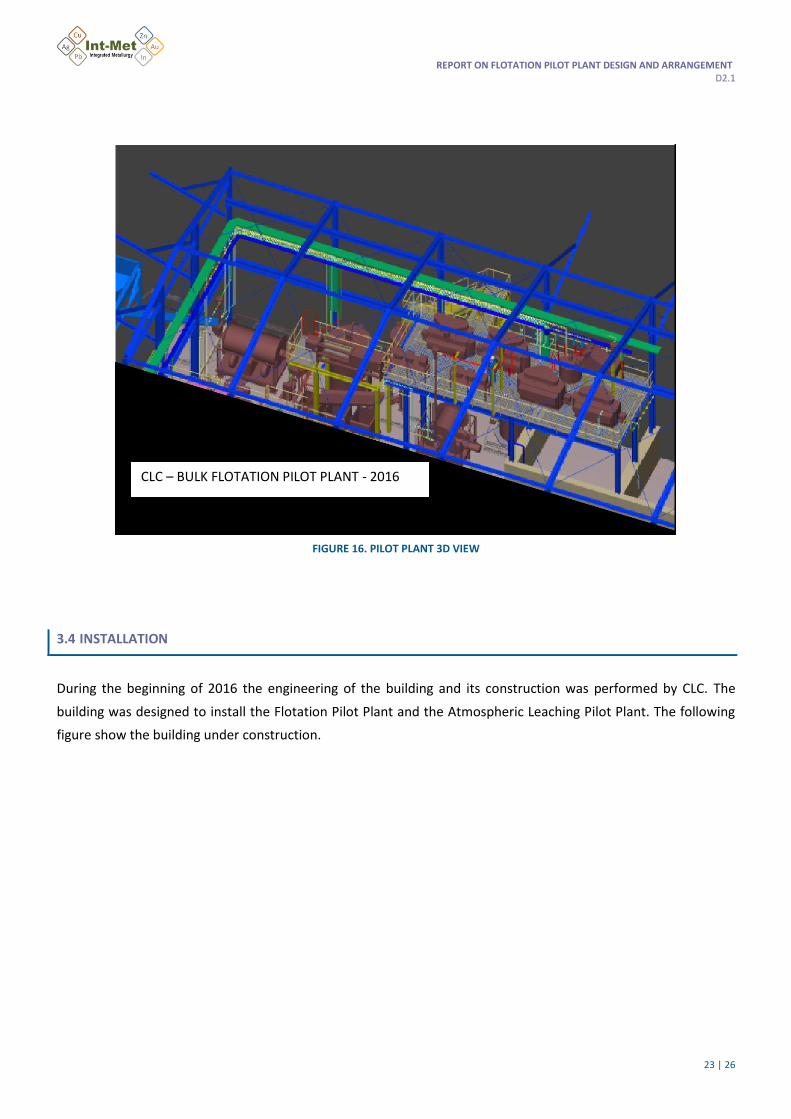
FIGURE 16. PILOT PLANT 3D VIEW ........................................................................................................................................................... 23
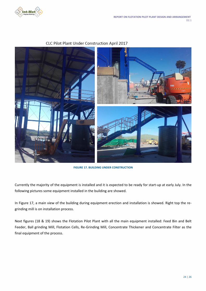
FIGURE 17. BUILDING UNDER CONSTRUCTION ........................................................................................................................................ 24
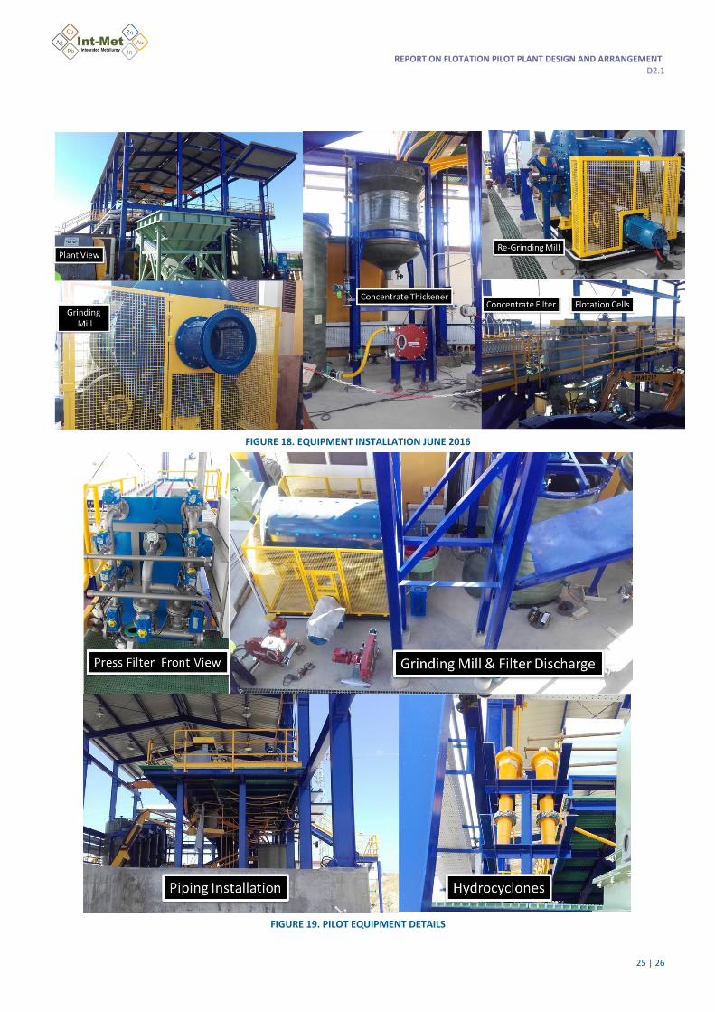
FIGURE 18. EQUIPMENT INSTALLATION JUNE 2016 .................................................................................................................................. 25
FIGURE 19. PILOT EQUIPMENT DETAILS ................................................................................................................................................... 25
REPORT ON FLOTATION PILOT PLANT DESIGN AND ARRANGEMENT D2.1
5 | 26
LIST OF TABLES
TABLE 1: CATIONIC COLLECTORS
TABLE 2: STRUCTURAL FORMULAS OF SODIUM SALTS OF ANIONIC COLLECTORS
TABLE 3: ANIONIC SULFHYDRYL COLLECTORS
TABLE 4: CO-ADSORPTION ON MINERAL PARTICLES RESULTING IN THEIR FLOTATION DEPRESSION AND RESULTING
IN THEIR FLOTATION ACTIVATION
REPORT ON FLOTATION PILOT PLANT DESIGN AND ARRANGEMENT D2.1
6 | 26
ABBREVIATIONS AND ACRONYMS
EIP European Innovation Partnership on Raw Materials
REPORT ON FLOTATION PILOT PLANT DESIGN AND ARRANGEMENT D2.1
7 | 26
1. INTRODUCTION
INTMET is focused on a sustainable and efficient beneficiation of polymetallic, complex and low grade ores
including tailings and wastes. The concept is to produce bulk concentrates or middling concentrates that will be
efficiently treated through tailored leaching technology approach to produce added value refined metal
(commodities) like Cu, Zn and other metals and critical materials (e.g. Au, Ag, In, Co). This novel
hydrometallurgical process has the potential to treat existing complex or low grade concentrates from current
operating mines, opening the way to a new and profitable mining business model. Effluents originated in the
process will be reused and recycled, maximizing the recovering of dissolved metals. Besides, a very innovative
hydroprocessing to valorize sulphur (producing fertilizers) and recover iron from pyrite secondary raw materials
will be developed.
INTMET falls under the PolymetOre (EIP-RM Awarded Commitment) umbrella aiming to develop a sustainable and
efficient solution to process polymetallic, complex and low grade ores to allow exploitation of resources that are
unviable today by conventional routes due to their complexity or low grade. These valuable resources are
abundant in some European mining regions in Spain, Portugal, Poland, Serbia, Sweden, Greece, etc. INTMET
includes different innovative technologies to increase raw materials efficiency in EU mining business, allowing at
the end unlocking a substantial volume of difficult ores that are currently unviable to treat through conventional
ways.
An important part of the project is to develop the technological concept for bulk concentrate processing
producing metals with high recovery at low cost and using an environmental friendly approach (Workpackage 2 of
the INTMET Project). For that reason is necessary to define the proper route to produce above mentioned
concentrate (nowadays only marketable sulphides concentrates are available in mineral processing industry: Cu
concentrate, Zn concentrate & Pb concentrate). Tasks 2.1 & 2.2 of the project deal with improvement of
technology for comminution and flotation to define the most suitable process to produce a bulk concentrate. And
Task 2.3 consist on the work required to arrange a Flotation Pilot Plant that will produce the sample material for
further testing in the different Workpackages of the project (WP3 atmospheric leaching- WP4 Pressure leaching –
WP5 Bio-leaching).
The following text present the main results obtained during the works performed in Task 2.3 devoted to the
design of the Flotation Pilot Plant.
REPORT ON FLOTATION PILOT PLANT DESIGN AND ARRANGEMENT D2.1
8 | 26
2. FLOTATION OF SULPHIDE ORES
2.1 FLOTATION TECHNOLOGY
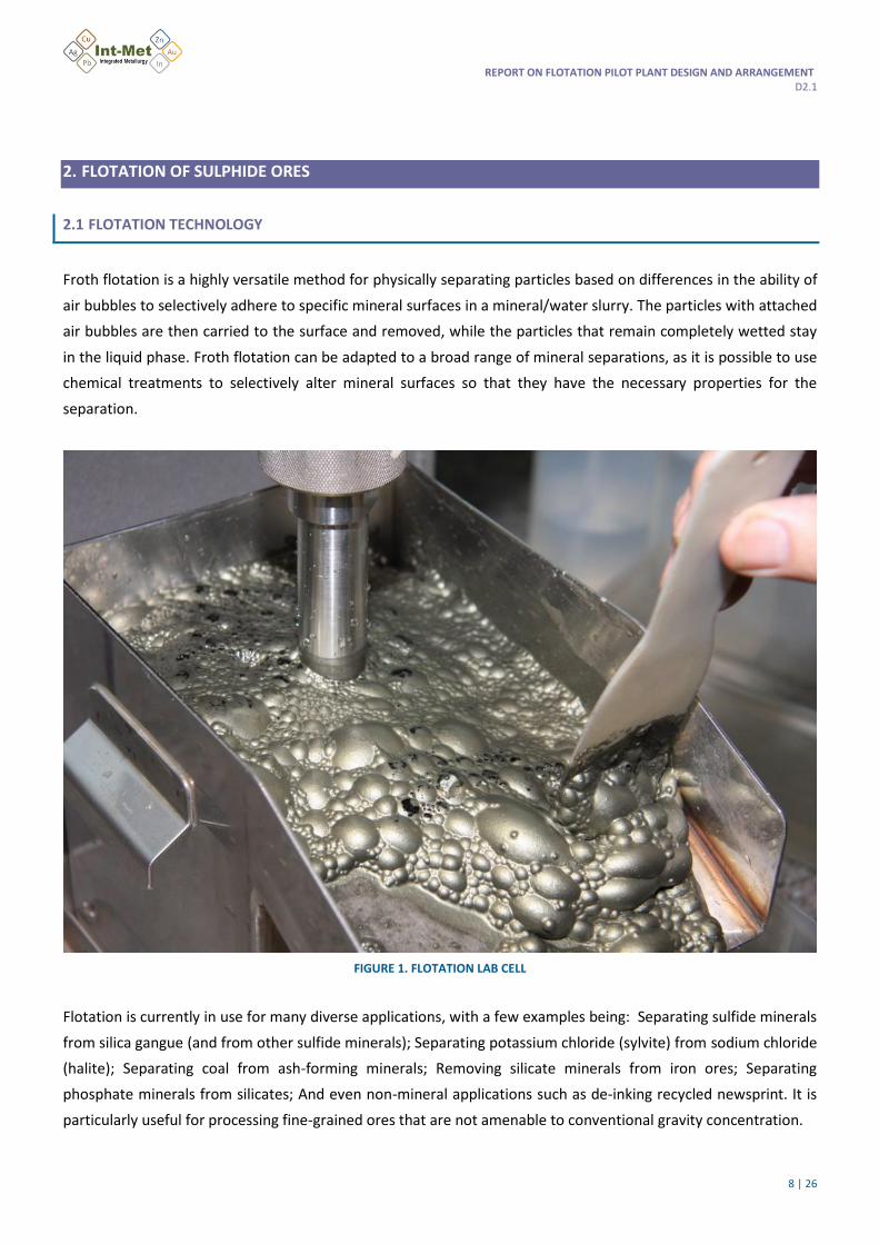
Froth flotation is a highly versatile method for physically separating particles based on differences in the ability of
air bubbles to selectively adhere to specific mineral surfaces in a mineral/water slurry. The particles with attached
air bubbles are then carried to the surface and removed, while the particles that remain completely wetted stay
in the liquid phase. Froth flotation can be adapted to a broad range of mineral separations, as it is possible to use
chemical treatments to selectively alter mineral surfaces so that they have the necessary properties for the
separation.
FIGURE 1. FLOTATION LAB CELL
Flotation is currently in use for many diverse applications, with a few examples being: Separating sulfide minerals
from silica gangue (and from other sulfide minerals); Separating potassium chloride (sylvite) from sodium chloride
(halite); Separating coal from ash-forming minerals; Removing silicate minerals from iron ores; Separating
phosphate minerals from silicates; And even non-mineral applications such as de-inking recycled newsprint. It is
particularly useful for processing fine-grained ores that are not amenable to conventional gravity concentration.
REPORT ON FLOTATION PILOT PLANT DESIGN AND ARRANGEMENT D2.1
9 | 26
The Flotation System Chemistry Components are mainly: Collectors, Frothers, Activators, Depressants and pH.
Operation Components are Feed Rate, Mineralogy, Particle Size, Pulp Density and Temperature. Equipment
Components are Cell Design, Agitation, Air, FlowCell, Bank Configuration, and Cell Bank Control.
The Industrial flotation system includes many interrelated components, and changes in one area will produce
compensating effects in other areas.
FIGURE 2. INDUSTRIAL FLOTATION PLANT
2.2 FLOTATION REAGENTS
A number of organic and inorganic reagents are used in flotation processes to achieve the desired separation.
These can be classified into collectors, frothers, extenders, activators, depressants, deactivators, flocculants and
dispersants.
REPORT ON FLOTATION PILOT PLANT DESIGN AND ARRANGEMENT D2.1
10 | 26
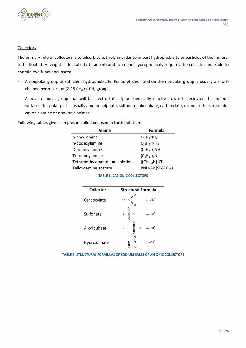
Collectors
The primary role of collectors is to adsorb selectively in order to impart hydrophobicity to particles of the mineral
to be floated. Having this dual ability to adsorb and to impart hydrophobicity requires the collector molecule to
contain two functional parts:
- A nonpolar group of sufficient hydrophobicity. For sulphides flotation the nonpolar group is usually a short-
chained hydrocarbon (2-15 CH2 or CH3 groups).
- A polar or ionic group that will be electrostatically or chemically reactive toward species on the mineral
surface. This polar part is usually anionic sulphate, sulfonate, phosphate, carboxylate, oxime or thiocarbonate,
cationic amine or non-ionic oximes.
Following tables give examples of collectors used in froth flotation:
Amine Formula
n-amyl amine C5H11NH2
n-dodecylamine C12H25NH2
Di-n-amylamine (C5H11)2NH
Tri-n-amylamine (C5H11)3N
Tetramethylammonium chloride [(CH3)4N]+Cl-
Tallow amine acetate RNH3Ac (96% C18)
TABLE 1. CATIONIC COLLECTORS
Collector Structural Formula
Carboxylate
Sulfonate
Alkyl sulfate
Hydroxamate
TABLE 2. STRUCTURAL FORMULAS OF SODIUM SALTS OF ANIONIC COLLECTORS
REPORT ON FLOTATION PILOT PLANT DESIGN AND ARRANGEMENT D2.1
11 | 26
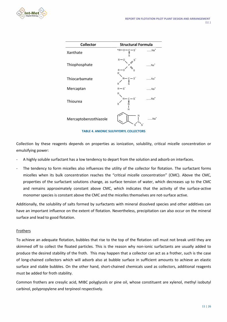
Collector Structural Formula
Xanthate
Thiophosphate
Thiocarbamate
Mercaptan
Thiourea
Mercaptobenzothiazole
TABLE 4. ANIONIC SULFHYDRYL COLLECTORS
Collection by these reagents depends on properties as ionization, solubility, critical micelle concentration or
emulsifying power:
- A highly soluble surfactant has a low tendency to depart from the solution and adsorb on interfaces.
- The tendency to form micelles also influences the utility of the collector for flotation. The surfactant forms
micelles when its bulk concentration reaches the “critical micelle concentration” (CMC). Above the CMC,
properties of the surfactant solutions change, as surface tension of water, which decreases up to the CMC
and remains approximately constant above CMC, which indicates that the activity of the surface-active
monomer species is constant above the CMC and the micelles themselves are not-surface active.
Additionally, the solubility of salts formed by surfactants with mineral dissolved species and other additives can
have an important influence on the extent of flotation. Nevertheless, precipitation can also occur on the mineral
surface and lead to good flotation.
Frothers
To achieve an adequate flotation, bubbles that rise to the top of the flotation cell must not break until they are
skimmed off to collect the floated particles. This is the reason why non-ionic surfactants are usually added to
produce the desired stability of the froth. This may happen that a collector can act as a frother, such is the case
of long-chained collectors which will adsorb also at bubble surface in sufficient amounts to achieve an elastic
surface and stable bubbles. On the other hand, short-chained chemicals used as collectors, additional reagents
must be added for froth stability.
Common frothers are cresylic acid, MIBC polyglycols or pine oil, whose constituent are xylenol, methyl isobutyl
carbinol, polypropylene and terpineol respectively.
REPORT ON FLOTATION PILOT PLANT DESIGN AND ARRANGEMENT D2.1
12 | 26
Extenders
In addition to frothers and collectors, non-ionic and nonpolar surface-active agents are used in to enhance the
hydrophobicity of the particles and the resultant flotation recovery. These reagents act by forming a multilayer
coating on the already partly hydrophobic surfaces. They can also act like frothers by co-adsorbing with collectors.
Activators
Many minerals do not adsorb collectors, so the special reagents are necessary to activate their adsorption. So, an
activator normally acts by adsorbing on the mineral, providing sites for adsorption of the collector species. As
example, copper sulphate acts as an activator for the flotation of sphalerite using xanthate as a collector at
relatively low concentration. Copper ion exchanges for zinc ion of the mineral surface, and the sphalerite particle
then behaves in flotation like a copper sulphide particle.
Depressants
Depressants retard or inhibit flotation of a desired solid. The depressing agent is adsorpted on the particle
surface, which pre-empts the collector from adsorbing and masks the adsorbed collector from the bulk solution
and achieves the particle does not exhibit a hydrophobic exterior. Chemicals used as depressants include
multivalent ions as phosphate, silicates, chromates, aluminium salts or organics. Common examples include
starch, tannin, quebracho and dextrin.
FIGURE 3. CO-ADSORPTION ON MINERAL PARTICLES RESULTING IN THEIR FLOTATION DEPRESSION AND RESULTING IN THEIR FLOTATION
ACTIVATION
Figure above illustrates depression of flotation through action of a cationic polymer; the same polymer can
activate flotation using an anionic collector.
Deactivators
Deactivators react with activators to form inert species and prevent flotation.
Dispersants and flocculants
Flotation is often hampered by the presence of fine particles or slimes, which can coat the coarser mineral
particles and consume excessive amounts of reagent because of their large specific surface areas. To solve this
problem dispersants are used in order to disperse these slimes.
REPORT ON FLOTATION PILOT PLANT DESIGN AND ARRANGEMENT D2.1
13 | 26
Flocculants are used to deal with fines. Polymers are used to flocculate particles into larger aggregates or flocs by
forming bridges between them. On mineral particles, adsorption of polymers is attributed to hydrogen bonding
between functional groups, or chemical or electrostatic bonding between polymer functional groups and surface
sites. Then, it is followed by separation of the flocs.
pH as Modifier
The pH in the pulp is a key variable to maximize recovery and selectivity, so it must be carefully controlled. Lime,
sodium hydroxide, sodium carbonate, ammonia, hydrochloric acid or sulphuric acid are used to control pH.
2.3 INDUSTRIAL FLOTATION EQUIPMENT
The purpose of flotation machines is to ensure the flow of the pulp into good, active contact of particles with
bubbles and the levitation of mineral-laden air bubbles to the top of the cell, allowing the removal of entrapped
particles.
A mechanical flotation cell consists of a vessel or a tank fitted with an impeller or rotor. The impeller agitates the
slurry to keep particles in suspension, disperses air into fine bubbles and provides an environment in the cell tank
for interaction of bubbles and hydrophobic particles and separation of valuable mineral particles from the
undesired gangue mineral particles.
The major manufacturers and different design features of flotation cells to be highlighted at present are the
following described below.
Bateman Cell
Bateman flotation cells (BQR serie) have a round tank design (cell sizes vary from 5 m3 to 100 m3). The mechanism
of these cells consists of a hemispherical-shaped impeller connected to a solid drive shaft. The impeller has no
disc on the top, so the blades are opened top and bottom opened. The drive shaft is shrouded with a stand pipe.
Through the gap between the standpipe and the shaft air is supplied into the mechanism by a forced entry mode.
It also has an overhung-type stator which is connected to the bottom of the standpipe and composed of a
horizontal hood with baffle plates projecting downwards.
REPORT ON FLOTATION PILOT PLANT DESIGN AND ARRANGEMENT D2.1
14 | 26
FIGURE 4. BATEMAN FLOTATION CELL DIAGRAM
Dorr-Oliver Cells
The Dorr-Oliver cell is marketed by FLSmidth Dorr-Oliver Eimco in a wide range of sizes, form 0.03 m3 to 200 m3.
Cell tanks on all large Dorr-Oliver flotation cells are truncated, conical bottom, round tanks or U-shaped in cross-
section. Corners are eliminated, and the conical bottom or U-shape helps to feed slurry into the pump action of
the rotor and prevent shortcircuiting.
FIGURE 5. DORR-OLIVER FLOTATION CELL DIAGRAM
REPORT ON FLOTATION PILOT PLANT DESIGN AND ARRANGEMENT D2.1
15 | 26
This mechanism consists of a hemispherical-shaped impeller fitted to a hollow shaft. Air is introduced to the
impeller through the hollow shaft, being a forced air entry mode. Stators are generally mounted on the bottom
but in the large cells mechanisms these are overhung.
Wemco Cells
Wemco has long been a trusted and proven leader in flotation technology under the FLSmidth Dorr-Oliver Eimco
brand.
There are two major Wemco designs, the Wemco 1+1 and new SmartCell:
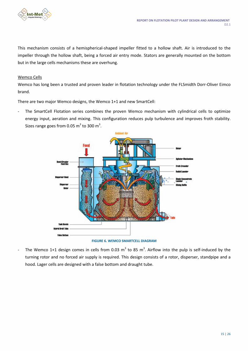
- The SmartCell Flotation series combines the proven Wemco mechanism with cylindrical cells to optimize
energy input, aeration and mixing. This configuration reduces pulp turbulence and improves froth stability.
Sizes range goes from 0.05 m3 to 300 m3.
FIGURE 6. WEMCO SMARTCELL DIAGRAM
- The Wemco 1+1 design comes in cells from 0.03 m3 to 85 m3. Airflow into the pulp is self-induced by the
turning rotor and no forced air supply is required. This design consists of a rotor, disperser, standpipe and a
hood. Lager cells are designed with a false bottom and draught tube.
REPORT ON FLOTATION PILOT PLANT DESIGN AND ARRANGEMENT D2.1
16 | 26
FIGURE 7. WEMCO 1+1 DIAGRAM
In both Wemco cells, rotor size, speed and submergence in the pulp determine the air and pulp circulation into
the cell. Therefore, liquid circulation and air transfer are function of rotor speed, size and submergence.
Outokumpu Cells
Outokumpu produces different flotation machines which can be categorized as:
1. OK conventional flotation machines: for rougher, scavenger and cleaner flotation.
2. TankCell flotation machines: for rougher and scavenger flotation.
3. SkimAir flotation units: for flash flotation.
4. High-Grade flotation machines: for cleaner flotation.
OK conventional flotation cells are available in volumes up to 38 m3. Conventional cells have a rectangular tank
design for cells up to 3 m3 and U-shaped tank above 3 m3 and up to 38 m3.
TankCell designs are available from volumes of 5 m3 to 500 m3. These cells are cylindrical with flat bottom.
REPORT ON FLOTATION PILOT PLANT DESIGN AND ARRANGEMENT D2.1
17 | 26
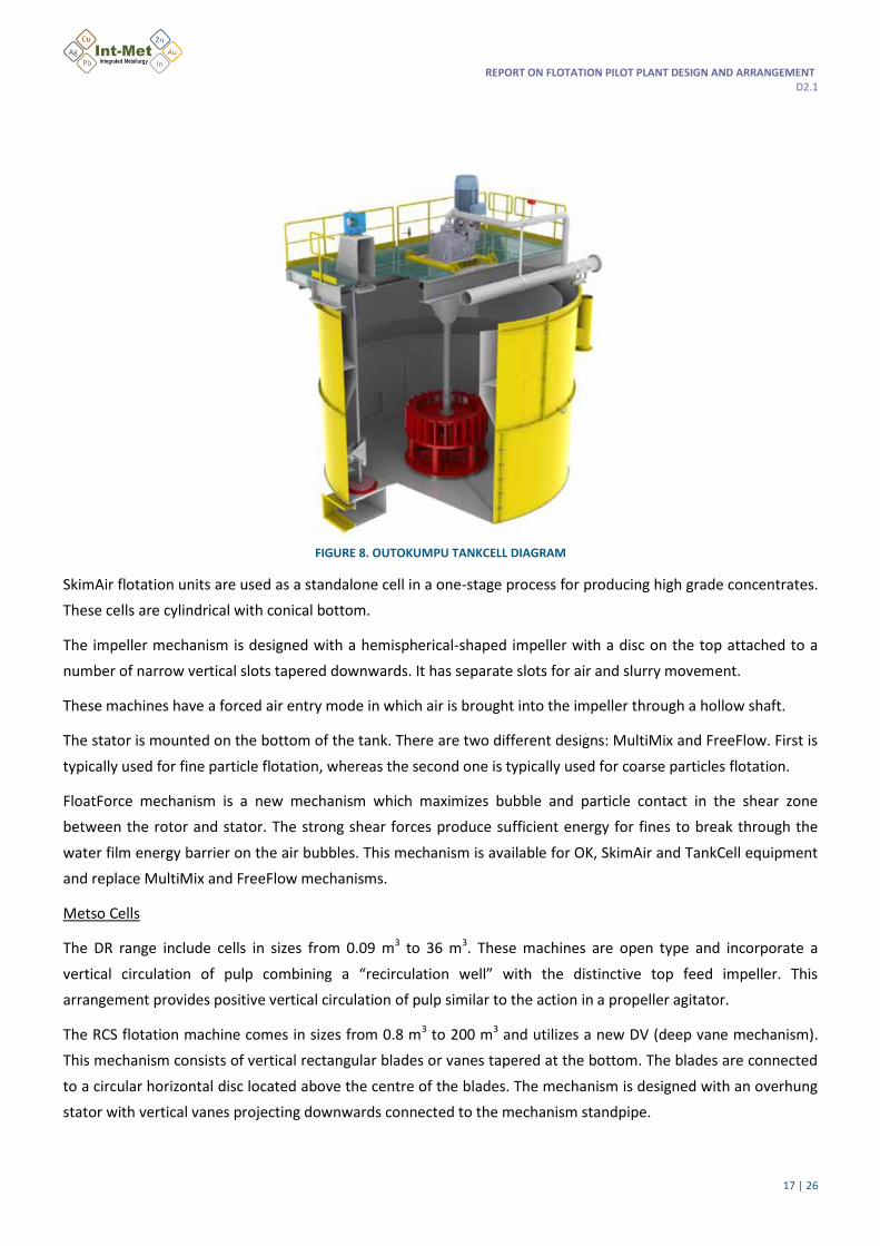
FIGURE 8. OUTOKUMPU TANKCELL DIAGRAM
SkimAir flotation units are used as a standalone cell in a one-stage process for producing high grade concentrates.
These cells are cylindrical with conical bottom.
The impeller mechanism is designed with a hemispherical-shaped impeller with a disc on the top attached to a
number of narrow vertical slots tapered downwards. It has separate slots for air and slurry movement.
These machines have a forced air entry mode in which air is brought into the impeller through a hollow shaft.
The stator is mounted on the bottom of the tank. There are two different designs: MultiMix and FreeFlow. First is
typically used for fine particle flotation, whereas the second one is typically used for coarse particles flotation.
FloatForce mechanism is a new mechanism which maximizes bubble and particle contact in the shear zone
between the rotor and stator. The strong shear forces produce sufficient energy for fines to break through the
water film energy barrier on the air bubbles. This mechanism is available for OK, SkimAir and TankCell equipment
and replace MultiMix and FreeFlow mechanisms.
Metso Cells
The DR range include cells in sizes from 0.09 m3 to 36 m3. These machines are open type and incorporate a
vertical circulation of pulp combining a “recirculation well” with the distinctive top feed impeller. This
arrangement provides positive vertical circulation of pulp similar to the action in a propeller agitator.
The RCS flotation machine comes in sizes from 0.8 m3 to 200 m3 and utilizes a new DV (deep vane mechanism).
This mechanism consists of vertical rectangular blades or vanes tapered at the bottom. The blades are connected
to a circular horizontal disc located above the centre of the blades. The mechanism is designed with an overhung
stator with vertical vanes projecting downwards connected to the mechanism standpipe.
REPORT ON FLOTATION PILOT PLANT DESIGN AND ARRANGEMENT D2.1
18 | 26
FIGURE 9. RCS FLOTATION MACHINE
2.4 INDUSTRIAL FLOTATION PROCESSES
Current industrial flotation processing for Metals recovery are focused on separate commercial concentrates to
be used on Copper, Zinc and Lead refineries. Depending on the feed ore different reagent combination and
flotation stages (including grinding and regrinding) are used. In the case of sulphides one of the major issues is the
pyrite content in the ore that must be depressed in the flotation process for purification purpose. In the case of
zinc the necessity of an activator as copper sulphate is the base for an effective metal recovery. Different reagents
combinations are used (collectors, modifiers, etc) with the aim of producing the final concentrates.
In the next figures the diagrams showing concentrates production from different raw materials are presented.
REPORT ON FLOTATION PILOT PLANT DESIGN AND ARRANGEMENT D2.1
19 | 26
FIGURE 10. COPPER CONCENTRATE FLOTATION FLOWSHEET
FIGURE 11. LEAD & ZINC CONCENTRATES FLOWSHEETS
Main stages included in all the processing routes are: Conditioning, Rougher, Scavenger, Cleaning, thickening and
Filtration. Grinding and Regrinding (including the necessary classification operation unit) stages are needed to
ensure mineral liberation from gangue.
REPORT ON FLOTATION PILOT PLANT DESIGN AND ARRANGEMENT D2.1
20 | 26
3. BULK FLOTATION PILOT PLANT DESIGN
In accordance with the objectives of the INTMET project the high recovery of metals from polymetallic and
complex ores are needed. Producing separate commercial concentrates, as current technology does, metals
recovery are low and, at the same time, processing cost are high. For that reason bulk concentrate production is
the best option and the flotation pilot plant must be designed with this final aim.
3.1 DESIGN BASIS
Main design basis for pilot plant design are as follows: