Page 1
©The contents of this report are property of A1 Consulting Group, Inc. Any reproduction, copying or use of its contents other than by the designated user for the specific project will be held against the user and can result in civil action.
A1 Project No # 10-070 PREPARED BY: A1 Consulting Group, Inc. Consulting Engineers, Surveyors, Planners, Construction Managers 117 International Drive Morrisville, NC 27560
REPORT ON SUBSURFACE
EXPLORATION AND
GEOTECHNICAL ENGINEERING
ANALYSIS
For the
PROPOSED BOX CULVERT
UNIVERSITY DRIVE, DURHAM, NC
September, 2011
Page 2
A1 Consulting Group, Inc 117 International Drive
Aka: NFE Technologies, Inc. Morrisville, NC 27560 Planners, Engineers & Surveyors Environmental Scientists Construction Managers http://www.a1consultinggroup.com
117 International Drive Morrisville, NC 27560 (919) 469-4800 Email: [email protected] http://www.a1consultinggroup.com
September 07, 2011 Kenneth E. Trefzger, PE, CFM HDR, Inc. 3733 National Drive, Suite 207 Raleigh, NC 27612-4845 Re: Revised Geotechnical Report of the Proposed Box Culvert at the
University Drive, for the City of Durham, NC (A1 Project No: 10- 070) Dear Mr. Trefzger, We are pleased to submit to you our revised report on the subsurface exploration and geotechnical recommendation for the proposed Box Culvert at the University Drive, for the City of Durham, NC The purpose of the exploration was to evaluate the general subsurface conditions within the proposed box culvert and pavement areas with regard to the design and construction of the culvert and pavement systems. This report presents our findings, conclusions and recommendations for foundation design, as well as construction considerations for the proposed foundations and paved areas. A1 appreciates the opportunity to assist you during this phase of the project. If you should have any questions concerning this report, or if we may be of further assistance, please contact us. We look forward to our continued relationship. Respectfully submitted, A1 Consulting Group, Inc.
V. K Goel, Ph.D., PE H. William Boyd, Ph.D., PG President Chief Geologist
Report prepared by: James Connors, PE
Page 3
University Drive Culvert Page 2 A1 Project 10-070
TABLE OF CONTENTS
Letter of Transmittal 1
Table of Contents 2
Project Understanding 4
Project Design Summary 5
1.0 Project Information 6
1.01 Project Overview 6
1.02 Background and Site 6
1.03 Loading Information 6
1.04 Purpose and Scope of Services 7
1.05 Proposed Construction 8
1.06 Investigation Summary 8
1.07 Report Overview 11
2.0 Site and Subsurface Description 11
2.01 Site Location and Description 11
2.02 Site Geology and Soils 11
2.03 Subsurface Conditions 12
2.04 Groundwater 13
3.0 Structural Discussion 14
3.01 Seismic Classification 14
3.02 Foundations 14
3.03 Settlement Analysis 14
4.0 Geotechnical Recommendations 15
4.01 Shrinkage and Swell Factors 15
4.02 General Site Development considerations 15
4.03 Highly Plastic Soils 16
4.04 Utilities 16
Page 4
University Drive Culvert Page 3 A1 Project 10-070
4.05 Construction Dewatering 17
4.06 Earth Slopes 17
4.07 Foundation recommendations 18
4.08 Retaining Structures 19
4.09 Earth Pressures 20
4.10 Reinforced Soil Structures 21
4.11 Pavement design Recommendations 21
5.0 Construction Recommendations 22
5.01 Site Grading and Earthwork 22
5.02 Temporary Shoring 23
5.03 Temporary Excavation Stability 24
5.04 Structural Fill 24
5.05 Effects of Construction Methods 25
6.0 General Conditions and Notes 26
6.01 General Conditions 26
6.02 Procedures Regarding Field Logs, Laboratory 27
6.03 Additional Services 28
Appendix 29
Figure 1 - Site Location and Vicinity Maps
Figure 2 - Boring Location Maps
Figure 3 – Culvert Profile with Boring locations
Figure 4 - Existing Site Conditions Photographs
Table 1 – SPT Values
Table 2 - Laboratory Results
Legend Sheet – Soil Classification
Boring Logs and Profile
Rock Quality Analysis
Seismic Analysis Table
NC Geological Map
Earthquake Forces calculation
Page 5
University Drive Culvert Page 4 A1 Project 10-070
PROJECT UNDERSTANDING
We understand that A1 Consulting Group, Inc was hired by the HDR
Engineering Company to perform the following services on the proposed
relocation of Box Culvert at the University Drive for the City of Durham, NC:
1. Evaluate the subsurface soil and groundwater information based on
drilling work performed by us on site.
2. Assess Site Geology
3. Earthwork recommendations for site grading
4. Review construction procedures for site work
5. Recommendations on earth slopes and their stability.
6. Recommendations on seismic classification and active forces.
7. Evaluation of soil bearing pressure
8. Recommendations on footings for the box culvert.
9. Recommendations on concrete rigid pavement design above the box culvert.
10. Recommendations on retaining walls for the box culvert.
11. Recommendations on the temporary shoring for the box culvert.
12. Recommendations on structural fill materials.
13. Quality control measures for construction.
Page 6
University Drive Culvert Page 5 A1 Project 10-070
PROJECT DESIGN SUMMARY:
The proposed project consists of the site investigation for the relocation of a concrete box
culvert at the University Drive for the City of Durham, NC. The purpose of this geotechnical
exploration was to determine the subsurface conditions as an aid to the structural
recommendations for a 350-linear feet long double 5’x5’ reinforced concrete box culvert.
For this purpose, six (6) borings were drilled at locations determined in consultation with the
client. The borings were all advanced to predetermined depths ranging from 20 to 25 feet.
Rock coring was conducted in select borings. Groundwater was measurable at the time of
drilling; however seasonal variations in the groundwater levels can be expected.
The following parameters may be used for the design of foundations:
Expected Loading Vehicles 8,000 vehicles per day on University Drive Horizontal Not provided
Foundation Type Spread Footings / Thickened slab Foundation Base natural excavated ground, engineered fill soils
and #57 stone. Undercut and replace unsuitable soils.
Average bearing pressure 1,500 PSF (to be field verified during construction) Construction De-watering may be necessary Water level considered for design varies Minimum Foundation width: 84 inch (bottom of the box culvert) Minimum depth of footings: 72 inch (below the concrete pavement) Settlement, as per design parameters: **
Maximum ¾ inch Differential ¾ inch Pavement 6” ABC base 2.5 /3.5 inch of asphalt pavement in parking lot
Handling of existing utilities Will be required Rock excavation May be required Floodplain & wetlands May be applicable
*Note: structural foundation bases must be field verified by a professional Geotechnical
Engineer for adequate bearing capacity prior to pouring concrete.
**Note: settlements are estimated based upon design parameters and observed
subsurface conditions. A professional Geotechnical Engineer should verify subsurface
conditions during excavation in order to determine if undercutting is required.
Assumptions and Exclusions/Limitations:
Client supplied information is accurate
Information in this report is to be used for planning and initial design purposes only
Borehole observations are assumed to approximate actual subsurface conditions
Information in this report is not intended to be used for bid purposes
Page 7
University Drive Culvert Page 6 A1 Project 10-070
Project Information 1.01 Project Overview:
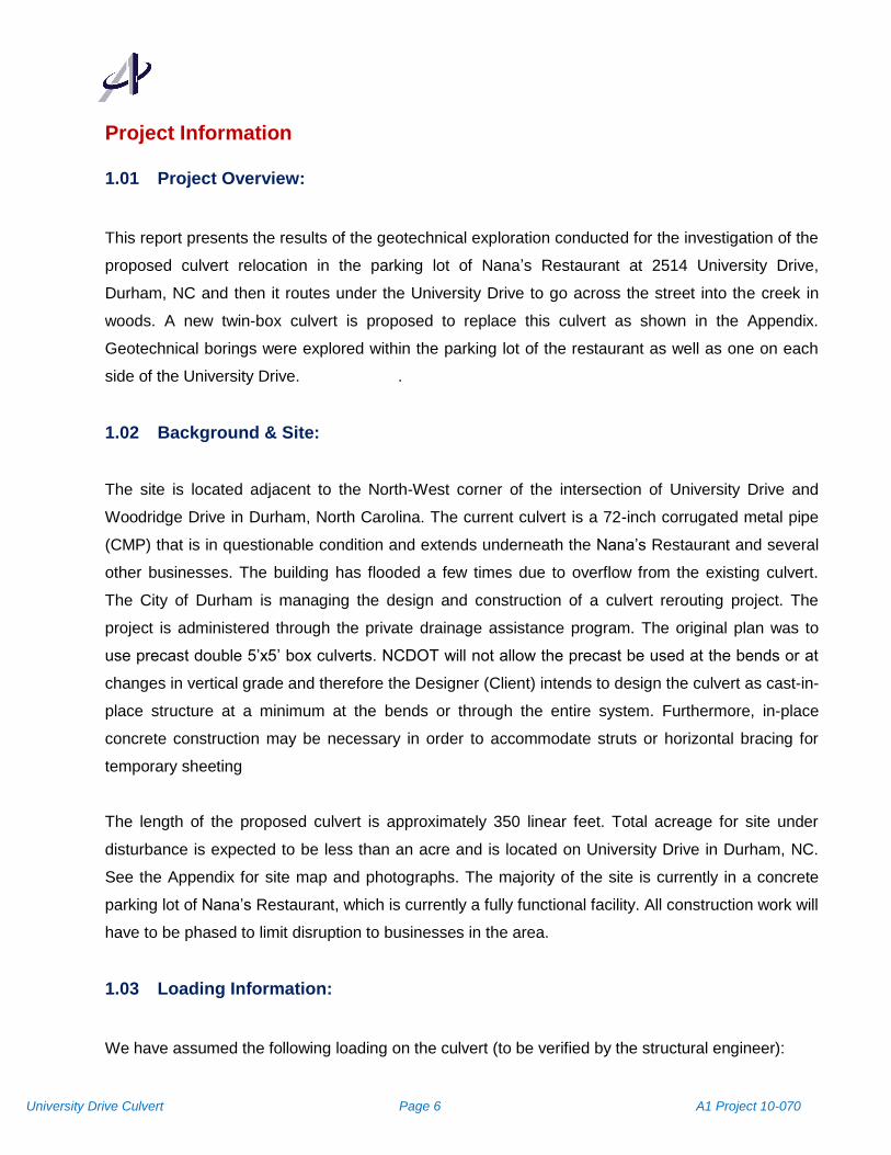
This report presents the results of the geotechnical exploration conducted for the investigation of the
proposed culvert relocation in the parking lot of Nana’s Restaurant at 2514 University Drive,
Durham, NC and then it routes under the University Drive to go across the street into the creek in
woods. A new twin-box culvert is proposed to replace this culvert as shown in the Appendix.
Geotechnical borings were explored within the parking lot of the restaurant as well as one on each
side of the University Drive. .
1.02 Background & Site:
The site is located adjacent to the North-West corner of the intersection of University Drive and
Woodridge Drive in Durham, North Carolina. The current culvert is a 72-inch corrugated metal pipe
(CMP) that is in questionable condition and extends underneath the Nana’s Restaurant and several
other businesses. The building has flooded a few times due to overflow from the existing culvert.
The City of Durham is managing the design and construction of a culvert rerouting project. The
project is administered through the private drainage assistance program. The original plan was to
use precast double 5’x5’ box culverts. NCDOT will not allow the precast be used at the bends or at
changes in vertical grade and therefore the Designer (Client) intends to design the culvert as cast-in-
place structure at a minimum at the bends or through the entire system. Furthermore, in-place
concrete construction may be necessary in order to accommodate struts or horizontal bracing for
temporary sheeting
The length of the proposed culvert is approximately 350 linear feet. Total acreage for site under
disturbance is expected to be less than an acre and is located on University Drive in Durham, NC.
See the Appendix for site map and photographs. The majority of the site is currently in a concrete
parking lot of Nana’s Restaurant, which is currently a fully functional facility. All construction work will
have to be phased to limit disruption to businesses in the area.
1.03 Loading Information:
We have assumed the following loading on the culvert (to be verified by the structural engineer):
Page 8
University Drive Culvert Page 7 A1 Project 10-070
Parking Lot:
We have estimated that the traffic volumes for the pavements on the site will be approximately 250
automobiles per day with ten-percent delivery trucks and service vehicles. For purpose of this report,
we have estimated maximum weight of delivery truck to be 50,000 pounds.
University Drive:
Total vehicular traffic on the University Drive at the site: estimated 8,000 vehicles per day with 10%
heavy trucks.
If actual traffic volumes are greater than these assumed and reported volumes, please notify us and
we will review our recommendations for applicability to the higher traffic.
1.04 Purpose and Scope of Services:
The purpose of this geotechnical exploration was to determine the subsurface conditions in order to
provide recommendations regarding the design of the concrete box culvert. The following activities
were conducted during our investigations:
Advanced a total of six (6) soil test at locations determined by the client. Four of these
borings were in the concrete parking lot, one boring was in asphalt pavement at the
shoulder of University Drive and one boring was in grass shoulder of the University Drive
at the other end of the culvert near the creek.
Prepared soil boring logs describing the types of soils encountered and other relevant
information. Sealed samples were carried to A1 laboratories.
Performed laboratory tests on selected soils samples (tests included determination of
grain size distribution, Atterberg Limits, moisture content, soil resistivity, pH, rock quality
determination, and California bearing ratio test).
Conducted geotechnical engineering evaluation of the available data to provide
recommendations regarding construction considerations such as subgrade preparation,
excavation, earthwork and groundwater control.
Geotechnical recommendations on box culvert foundation and walls, and pavements.
Prepared a report presenting all data, soil boring logs, observations and
recommendations.
Boring locations, boring quantities and target depths were all determined by the client. The scope
of services did not include an environmental assessment for determining the presence or absence of
Page 9
University Drive Culvert Page 8 A1 Project 10-070
wetlands or hazardous or toxic materials in the soil, surface water, groundwater, or air, on or below
or around the site.
1.05 Proposed Construction:
We understand that a new concrete box culvert will be built at the site. The box culvert could be a
combination of precast and cast-in-place or it could be all cast-in-place.
The anticipated site grading may be minimal. As indicated by the design civil engineer, the top of the
proposed box culvert at the inflow may be at elevation 307.0 LF and the top of the box culvert at the
outflow may be at elevation 303.0 LF. Proposed invert-in is at 301.24 LF and invert-out is 297.0 LF.
Box culvert will have a reinforced cast-in-place concrete slab on top and then an engineered fill. We
recommend asphalt pavement above that to accommodate any potential settlements within the
culvert area due to varied soft soils underneath.
Widening and repaving of University Drive are also expected but are not part of our project.
1.06 Investigation Summary:
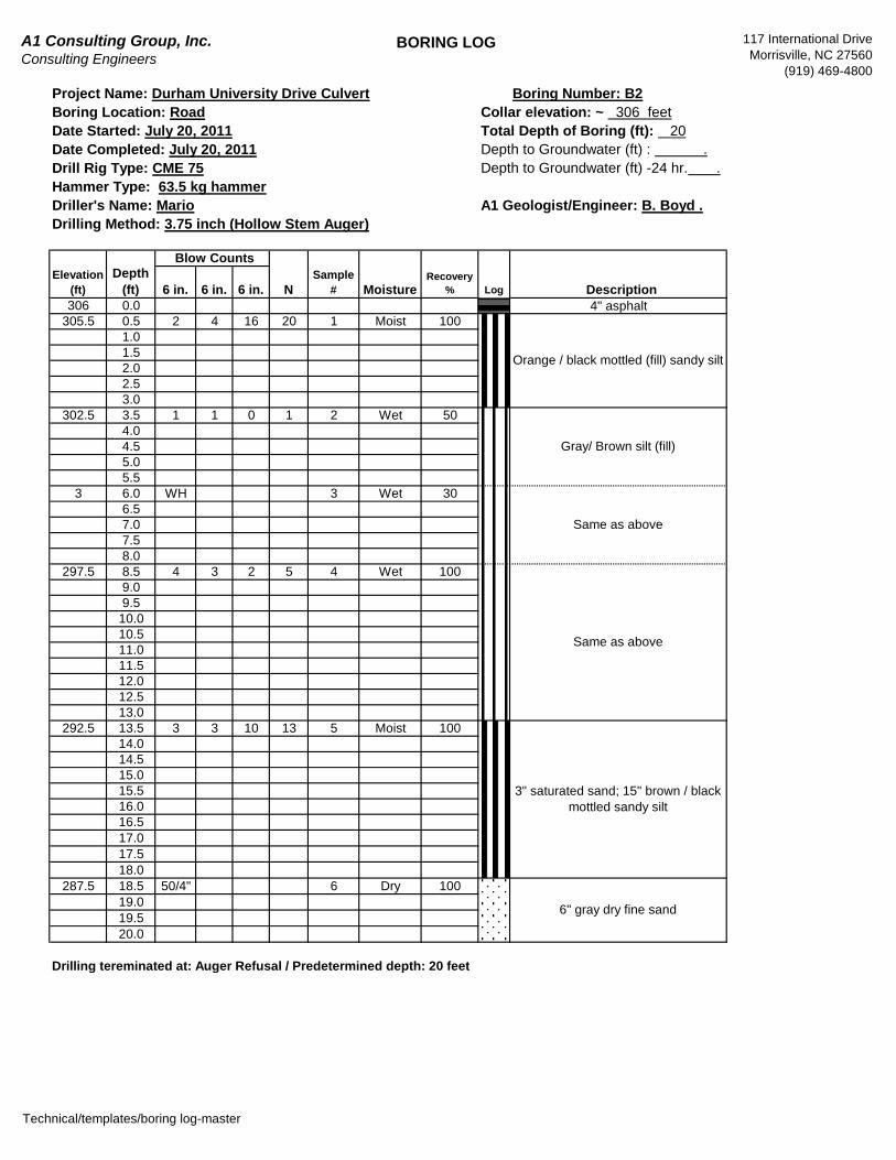
This phase of the subsurface investigation was conducted on July 20 and 21, 2011. The soil borings
were advanced using a truck-mounted drill rig fitted with 3.25-inch inside diameter rotary augers.
Split spoon samples (SPT) were taken, four in the top ten feet and one for every five feet thereafter.
To obtain the samples, the sampler was placed on the bottom of the borehole and driven to
penetrate to a depth of 18 inches (or to a maximum of 50 blows per 6 inches). The first 6 inches of
sampler penetration is considered as seating, and the sum of second and third 6-inch increments of
penetration (or a fraction thereof) is termed as the Standard Penetration Resistance (N-value). In
the case of continuous sampling the penetration distance is 24 inches, and the sum of the third and
fourth 6-inch increments are used to determine the N-value.
Boring locations were staked in the field by A1 from the client’s boring location site plan. A joint site
visit was conducted with the client’s project manager to confirm boring locations. All boring locations
were adjusted based on utilities interference and client’s requests. A boring location diagram
Page 10
University Drive Culvert Page 9 A1 Project 10-070
indicating the drilled boring locations is presented in the Appendix. All drilling and sampling
operations were conducted in general compliance with ASTM D 1586.
A1 staff had contacted the North Carolina One-Call Center (ULOCO) 72 hours in advance and they
had marked all the utilities on site.
Six (6) soil borings were advanced at staked locations as shown on the boring location plan. All
borings were extended to the auger refusal or as authorized by the client. The location of all borings
was as close as possible to the staked locations, subject to utilities interference and drilling
convenience.
Field boring logs were prepared incorporating the details such as blow counts, occurrence of ground
water, description of soils, rock, etc. Groundwater was measured at the time of drilling. The borings
were back-filled using on site auger cuttings. The site was cleaned and restored prior to
demobilization.
Standard Penetration Tests were performed at designated intervals in the soil test borings in general
accordance with ASTM D 1586 in order to obtain data for estimating soil strength and consistency.
In conjunction with the penetration testing, split-spoon soil samples were recovered for soil
classification and potential laboratory testing. Water level measurements were attempted at the
termination of drilling.
While in the field, a representative of the geotechnical engineer visually examined each sample to
evaluate the type of soil encountered, soil plasticity, moisture condition, organic content, presence of
lenses and seams, colors and apparent geological origin. The results of the visual soil
classifications for the borings, as well as field test results, are presented on the individual “Test
Boring Records,” included in the Appendix. Similar soils were grouped into strata on the logs. The
strata lines represent approximate boundaries between the soil types; however, the actual transition
between soil types in the field may be gradual in both the horizontal and vertical directions.
All SPT samples were carried in sealed containers and submitted to the A1 laboratory, where
selected samples were checked for moisture, gradation analysis, Atterberg limits, and USGS
classification. Additional tests were performed for soil resistivity and pH values. All rock samples
were carried in cardboard boxes and checked for RQD and rock integrity. The results of the
Page 11
University Drive Culvert Page 10 A1 Project 10-070
laboratory tests are included in the Appendix, and are summarized below. Three bulk samples from
borings along the present University Drive and parking lot were collected for pavement design
purposes.
Four grain size analyses, six natural moisture content analyses, three soil resistivity tests, and three
CBRs were performed. Grain size analysis was done on samples representative of the soils
encountered. Results are incorporated into the report below.
Beneath the topsoil and concrete pavement, each of the test borings encountered 6-feet to 13-feet
of silty SAND and/or sandy SILT Fill over sandy Clay / Clay SAND with Mica. Some of the borings
encountered partially weathered rock (PWR) or Rock. Ground water was encountered in several
borings (Boring # 4 at depth 8.4’ and boring # 5 At depth 12.0’). Some of the soil descriptions
include “plastic” silts. These materials exhibited standard penetration resistances of 2 to 4 blows per
foot. The provided laboratory test data indicated that the soils had approximately 45% passing the
#200 sieve. Liquid limits ranging from 20 to 26, and plasticity indices ranging from non-plastic to 12.
Three bulk samples tested using Standard Proctor techniques resulted in maximum dry densities of
117 to 122 pounds per cubic foot (PCF) at optimum moisture contents of 9 to 12 percent. All of the
moisture content tests indicated that the natural soil moisture content is above the optimum moisture
content for compaction (except in boring B5).
Soil pH and resistivity were measured in three borings to test for corrosive influences on the
proposed structure. The soil pH values as measured are generally not in the range to be considered
corrosive to concrete. Soil pH values above 6.0 are considered to be of low corrosivity potential.
Two of the pH values were slightly more acidic. Values in the range of 5.0 to 6.0 are considered to
be moderate risk for corrosiveness to concrete. Since much of the existing overburden appears to
be fill the pH values could vary within short distances.
Soil resistivity as measured indicates the soil to be corrosive to steel. Concrete is not as susceptible
to corrosion due to resistivity, but any exposed steel may be. If any steel is to be exposed to the
soils deeper than ten feet from the surface then some form of corrosion protection (such as an
epoxy or bituminous coating) may be justified.
Ground water levels at 24-hours of 8.4 to 12 feet below ground surface (BGS) were noted. Ground
water levels will fluctuate depending on seasonal variations of precipitation and other factors.
Page 12
University Drive Culvert Page 11 A1 Project 10-070
1.07 Report Overview:
The remainder of this report will discuss the surface and subsurface conditions at the project site
(Section 2.0), a discussion of observations and collected data (Section 3.0), and Recommendations
(Section 4.0). The Appendix contains site plans, maps, site photographs, tabulated data, boring logs
and cross sections illustrating and documenting the information in the report body.
2.0 Site and Subsurface Description
2.01 Site Location and Description:
The site is located adjacent to the N-W corner of the intersection of University Drive and Woodridge
Drive at Nana’s restaurant, 2514 University Drive, Durham, NC , mainly in a populated urban
commercial area of Durham, in Durham County, North Carolina.
The majority of the site is located under an existing concrete parking lot of the restaurant with a small
segment running under the University Drive leading into the creek.
The overall topography of the project site can be described as flat to mildly sloping towards the culvert
outfall. Total relief between the surface high point (311.0’) and the low point (307.0’) on the project is
approximately 4 feet.
No wetland studies were performed by A1.
We were informed that the project site is not within the FEMA-designated 100-year floodplain.
See Appendix for photographs of site conditions.
2.02 Site Geology and Soils:
The site is located within Durham County, North Carolina and is in the piedmont geologic province.
The piedmont is characterized by rolling topography with rounded hills and valleys.
The geological province of the site is the Durham Basin, characterized by sedimentary rocks. The
geology underlying the site and vicinity has been mapped as the Chatham Group, consisting of
Page 13
University Drive Culvert Page 12 A1 Project 10-070
conglomerate, sandstone and mudstone of Triassic age. The parent rock material is characterized
by a wide variation in grain sizes, (Geologic Map of North Carolina, North Carolina Geological
Survey, Raleigh, North Carolina, 1985).
The residual soils at the site are derived from the underlying sedimentary rocks, and are mapped as
Cartecay Series (Kirby, 1971). Cartecay soils, found in stream flood plains along smaller streams,
are poorly drained and consist of grayish brown to brown silty loam, sandy loam or sandy clay loam.
The soils have a moderate permeability and are moderate to strongly acidic. The shrink-swell
potential is low. Much of the soil may be poorly suited for foundations, and is fair for use as road fill.
(Kirby, Robert M.., 1970, Soil Survey of Durham County, North Carolina. United States Department
of Agriculture, Soil Conservation Service). With the increased depth, the soil becomes less
weathered, coarser grained and the structural character of underlying parent rock becomes more
evident. Soils underneath may become partially weathered rock with blow counts of 100 per foot or
greater. The bedrock depth is more than 5 feet.
2.03 Subsurface Conditions:
Details of soil conditions encountered in our field exploration program are shown on the individual soil
boring logs (B1 through B6) included in the Appendix. The soils present were largely composed of silt,
sand, or fine sandy silt. The following subsurface description is of a generalized nature, provided to
highlight the major soil strata encountered at the site. Boring logs should be reviewed for specific
information as to individual boring locations. The stratification of the soils, as shown on the soil boring
logs represents the soil conditions in the actual boring locations; other variations may occur and should
be expected between borings. Lines of demarcation represent the approximate boundary between
subsurface materials; the transition may be gradual. The general stratification may be found as follows:
A layer of organic topsoil. In the borings under pavement this layer is absent and replaced with
disturbed soil of a gravelly sand/soil mix.
A stratum consisting of very soft to very stiff dark brown, gray, orange mottled fine sandy silt.
This layer could extend to depths of up to 5 feet. Typical SPT N values for this stratum range
from 2 to 17.
A layer of loose to medium dense brown to gray silty or clayey sand. In this stratum there may
be lenses of clayey and silty material containing visible very fine mica. This stratum may extend
to about 13 feet. Typical SPT N values for this stratum range from 2 to 18.
Page 14
University Drive Culvert Page 13 A1 Project 10-070
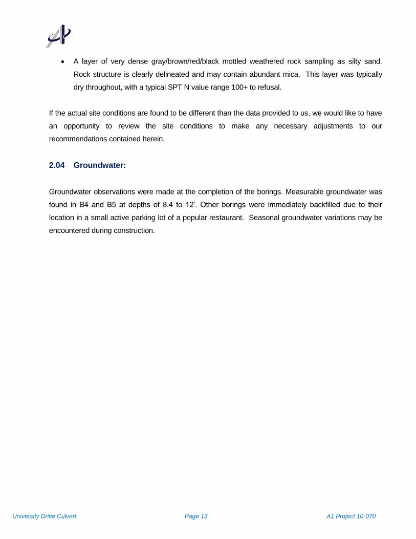
A layer of very dense gray/brown/red/black mottled weathered rock sampling as silty sand.
Rock structure is clearly delineated and may contain abundant mica. This layer was typically
dry throughout, with a typical SPT N value range 100+ to refusal.
If the actual site conditions are found to be different than the data provided to us, we would like to have
an opportunity to review the site conditions to make any necessary adjustments to our
recommendations contained herein.
2.04 Groundwater:
Groundwater observations were made at the completion of the borings. Measurable groundwater was
found in B4 and B5 at depths of 8.4 to 12’. Other borings were immediately backfilled due to their
location in a small active parking lot of a popular restaurant. Seasonal groundwater variations may be
encountered during construction.
Page 15
University Drive Culvert Page 14 A1 Project 10-070
3.0 Structural Discussions
The recommendations made in this report are based on the data obtained during the field
investigation program and laboratory testing.
3.01 Seismic Classification and Active Force on Culvert Wall:
Every structure should be evaluated to resist the effects of earthquake motions. The proposed site
is located in Durham, North Carolina.
Based on the International Building code 2009, the site is classified as Type E table 1615.1.1. Active
Force on Culvert Wall with Earthquake Forces was calculated using Mononobe-Okabe Equation and
is enclosed in the Appendix. Active Force per unit length of wall was calculated to be 1,500 PLF,
determined at a height of 2/3rd from bottom of culvert. Shear wave testing of the soils can be used to
provide a more thorough evaluation of the seismic classification of site. A 100-foot deep boring was
not required by the structural engineer due to size and height of the proposed structure.
3.02 Foundations:
Borings B1 through B6 show blow counts ranging from 3 to 80 blows per foot (bpf) approximately 9
feet below the ground surface. Based on the exploration, the soils encountered for this site
consisted of mostly brown fine sandy silt or silty sand. Bearing capacity calculations indicated that
a maximum allowable design soil bearing pressure of 1,500 PSF (gross) should be used for the
bottom of the box culvert footing. The footing base should be designed using a modulus of
subgrade reaction (k) of 100 pounds per cubic inch. In addition, the footing and culvert slab should
bear at a sufficient depth to provided adequate resistance to scour. A scour study was not part of
this investigation.
3.03 Settlement:
Based on the estimated settlement calculations, general stratigraphy in the building areas, past
experience with similar projects and the anticipated magnitude of the traffic loads, it is our opinion
that the total immediate settlement could be over 1-inch in the low blow count silts and differential
settlement potentials for the culvert should be on the order of ¾ of an inch. This conclusion is
contingent upon compliance with the site preparation and fills placement recommendations outlined
in this report.
Page 16
University Drive Culvert Page 15 A1 Project 10-070
4.0 Geotechnical Recommendations
4.01 Shrinkage and swell factors:
Based on our previous experience with similar soils, we recommend a shrinkage factor of 20 % and
a swell factor of 10 % for all excavations on this project.
The following recommendations are based on the information available on the proposed
construction, the subsurface data provided to us, and our experience with soils and subsurface
conditions similar to those described in the test boring records provided to us. Conditions may be
encountered during construction that are substantially different than those indicated by the borings.
In these instances, adjustments to the design and construction may be necessary depending on
actual conditions.
4.02 General Site Development Considerations
Any trees, underbrush, topsoil, roots, and other deleterious materials should be removed from the
proposed construction area. Special attention should be given to the removal of tree stumps within
the proposed construction area. Site clearing, grubbing, and stripping, should be performed only
during dry weather conditions. Operation of heavy equipment on the site during wet conditions
could result in excessive mixing of topsoil, humus and organic debris with clean underlying soils.
All relocation of existing underground utilities should be completed before site grading begins. The
ends of abandoned underground utilities should be permanently sealed to prevent the inadvertent
introduction of fluids into the construction area. Any septic tanks and drain fields within proposed
construction areas and 20 feet outside the construction limits should be excavated and removed.
We recommend that areas to receive structural fill be proofrolled prior to placement of structural fill.
Areas of proposed excavation should be proofrolled after rough finished subgrade is achieved.
Proofrolling should be performed using a loaded dump truck weighing at least 15 tons. Proofrolling
should be accomplished by performing at least 3 passes in each of two perpendicular directions
within entire construction areas, and 10 feet beyond. Any unsuitable materials that may be present,
and any low consistency soils that are encountered which cannot be adequately densified in place,
should be removed and replaced with well compacted fill material placed in accordance with the
Page 17
University Drive Culvert Page 16 A1 Project 10-070
Structural Fill section of this report. Proofrolling should be observed by our representative to
determine if remedial measures are necessary. Proofrolling should facilitate the identification of soft
surficial soils, but should not be expected to reveal soft conditions more than 2 feet below the
ground surface at the time of proofrolling. Footing examinations will be required to evaluate the
presence of deeper soft soils, which could adversely affect foundation support. Footing
examinations will be discussed later in this report.
Based on our experience on similar sites, there may also be buried obstructions such a boulders or
construction debris. On sites located in developed areas this is not an unusual occurrence. Such
buried materials occur in isolated areas which may not be detected by the soil test borings. Any
buried waste construction debris or trash which is found during the construction operation should be
thoroughly excavated, and the waste material should be removed from the site prior to placement of
fill soils.
After excavation, some heave of the soils should be expected. Additionally, creating an excavation
of this size could also allow inflow of ground water. Remedial measures should be expected in this
area at the time of construction to provide a suitable base for support of the culvert structure.
Site grading is expected in the planned road widening of University Drive. No test data has been
provided regarding subsurface conditions in the area of University Drive and is not within our scope
of services.
4.03 Highly Plastic Soils:
Soil boring logs indicate the presence of some moderately plastic soils on the site. If any highly
plastic soils occur at or near design subgrades their characteristic to shrink and swell with changes
in moisture can cause structural problems. In addition, these soils lose strength when wet. All
highly plastic soils within 3 feet of design subgrades under structures and within 2 feet of design
subgrade in areas to be paved should be removed and replaced with low plasticity materials. The
low plasticity materials should have a plastic index (PI) of less than 30.
4.04 Utilities:
Page 18
University Drive Culvert Page 17 A1 Project 10-070
We recommend any / all utility lines be located outside of planned construction areas, the trenches
cleaned of backfill soils, and, after utility emplacement, the trench backfilled with compacted fill as
recommended in this report. Past experience indicates utility trench backfill is often poorly
compacted. Also, cracked or deteriorated pipes can collapse, leak or serve as conduits for
subsurface erosion. Any of these conditions can result in excessive settlement of foundations and
pavements.
4.05 Construction Dewatering
The presence of ground water was encountered during drilling operation. Therefore, we do
anticipate that ground water control will be essentially required. However, ground water levels can
fluctuate. In areas where excavations are greater than 3 or 4 feet below the ground water level, or in
areas where trench dewatering proves to be ineffective, it may be necessary to use a well point
system or other methods to efficiently perform construction dewatering.
We must emphasize that dewatering requirements will be dictated by ground water conditions at the
time of construction. The contractor should use a technique or combination of techniques which
achieves the desired result under actual field conditions.
4.06 Earth Slopes
Because of the confined nature of the site, the depth of the excavation required for culvert
installation and the close proximity of the existing masonry building it will be necessary to
install some type of temporary earth support to protect both the workers and the building.
The contractor will be required to submit the proposed system to the owner for review by the
client prior to the start of construction.
There may be some locations where temporary construction slopes can be installed. If this option
becomes available then the temporary construction slopes should be designed in strict compliance
with the most recent OSHA regulations. The test borings indicate that most soils at the site are Type
C as defined in the Occupational Safety and Health Standards for the Construction Industry (29
CFR, Part 1926, Subpart P), July 1, 2001. This dictates that temporary construction slopes in
residual soils be no steeper than 1.5 horizontal to 1 vertical for excavation depths of up to 20 feet.
Flatter slopes may be required due to the presence of large volumes of mica within the soils, or in
Page 19
University Drive Culvert Page 18 A1 Project 10-070
areas where softer soils are encountered. We recommend that a “competent person” as defined in
the OSHA Regulations be present on site during excavations. Temporary construction slopes should
be closely observed for signs of mass movement: tension cracks near the crest, bulging at the toe of
the slope, etc. If potential stability problems are observed, the Geotechnical Engineer should be
immediately contacted. The responsibility for excavation safety and stability of construction slopes
should be solely with the contractor.
We recommend that permanent cut or fill slopes be approximately 3 (H) to1.0(V) to maintain long
term stability and to provide ease of maintenance. Slopes constructed steeper than 3(H) to 1.0(V)
could be highly susceptible to erosion, will be difficult to maintain, and could experience large scale
slope failure in some instances. However, steeper slopes under tight site conditions can be built
using the following stabilization methods. For fill slopes, use geogrid reinforcement. For cut slopes,
use soil nails or pile panel wall or other approved method. The crest or toe of cut or fill slopes should
be no closer than 15 feet to any building foundation. The crest or toe should be no closer than 10
feet to the edge of any pavements. For slope stability designs, contractor shall engage a
professional engineer to design alternates and get it approved from the owner.
4.07 Foundation Recommendations
After site preparation and site grading are complete, it is our opinion that the proposed box culvert
may be supported on conventional shallow foundations. We recommend the use of a design
allowable soil bearing pressure of 1,500 pounds per square foot (PSF).
Portions of the footings for this project may bear on new structural fill material. For this reason, we
must emphasize the importance of quality control during the placement of structural fill.
Performance of building foundations which are supported by structural fill material will depend
largely on achieving the recommended level of compaction on fill materials. Compacted soil
densities less than the recommended percentage of the standard Proctor maximum dry density
could result in excessive foundation settlement.
There may be locations where undercut of the existing soil is required in order to achieve the
necessary 1500 psf bearing capacity. Access to these may not allow for the placement of the
standard structural fill. In these areas the undercut material can be replaced with # 57 stone
wrapped in filter fabric.
Page 20
University Drive Culvert Page 19 A1 Project 10-070
It is possible that during construction, some of the existing soils at the project site will have an
allowable soil bearing pressure less than the recommended design value. Therefore, foundation
bearing surface evaluations will be critical to aid in the identification of such soils and to enable the
development of remedial measures.
Detailed foundation examinations should be performed in each foundation excavation prior to
placement of reinforcing steel. These examinations should be performed by our representative to
confirm that the design allowable soil bearing pressure is available. The footing examinations
should be performed using a combination of visual observation, hand rod probing, and dynamic
cone penetrometer testing. Dynamic cone penetrometer testing, as described in ASTM STP-399,
should be performed in the entire length of culvert foundation at no greater than 50 foot intervals in
staggered locations. If the soil is found to have an unsatisfactory bearing capacity, our inspector will
review the problem with our project Geotechnical Engineer.
Remedial measures should be based on actual field conditions. However, in most cases we expect
the use of the stone replacement techniques to be the primary remedial measure.
Exposure to the environment may weaken the soils at the foundation bearing surface, if they are
exposed for extended periods of time. If the foundation bearing surface becomes softened due to
exposure, the soft soils should be removed prior to placement of concrete.
4.08 Retaining Structures:
The following lateral earth pressure coefficients, assuming a level backfill surface and no excess
hydrostatic pressure are given below.
Description #57 Stone On-Site Silty SAND or Sandy SILT Soils
Ø = 34° Ø = 32°
At-rest Coefficient, Ko 0.33 0.44 0.47
Active Coefficient, Ka 0.20 0.28 0.31
Passive Coefficient, Kp 5.00 3.54 3.25
Moist Unit Weight 105 pcf 118 pcf
Soil/Concrete Friction Factor 0.50 0.3
Page 21
University Drive Culvert Page 20 A1 Project 10-070
Friction angle for soils can be used as 33° for design; and friction angle between soil and concrete is
21°
For soils of this nature, the fill slopes should be compacted to 95% relative density and should be
protected from erosion by vegetation or other means. Cut and fill slopes of 3H: 1V or flatter may be
desirable for mowing and other maintenance purposes. Should constructed slopes be required for
this project, it is recommended that a geotechnical engineer be contacted to perform slope stability
analysis.
4.09 Earth Pressure
For the design of the lateral pressures acting on the sides of the culvert box, Ko for the on-site soils
should be used.
If cantilever sheeting is used to protect the adjacent buildings during construction. Ka of the on site
soils should be used for the lateral pressure design.
If horizontal braced sheeting is used Ko of the on-site soils should used. for the lateral pressure
design.
The ground water unit weight should be used if no drainage system is incorporated behind retaining
walls. The development of excessive water pressure is a common cause of retaining wall failures.
Drainage systems should be carefully designed to insure that long term permanent drainage is
accomplished.
For the evaluation of the resistance of soil to lateral loads, which is frequently necessary for
evaluating the stability of retaining walls, and laterally loaded foundations, the passive earth
pressure must be calculated. The passive earth pressure can be calculated using the same basic
equation described above with the coefficient of passive pressure, Kp, as follows:
Kp = 4.02 for soil types SP and SP-SM
Kp = 3.54 for soil type SM
Kp = 3.25 for soil types ML
Kp= 2.76 for soil type CL
Page 22
University Drive Culvert Page 21 A1 Project 10-070
It should be noted that full development of passive pressure requires deflections toward the soil
mass on the order of 1.0% to 4.0% of total wall height.
For analysis of sliding resistance of the base of a retaining wall, the coefficient of friction may be
taken as 0.3 for the micaceous silts reported to be present at the project site. The force which
resists the base sliding is calculated by multiplying the normal force on the base by the coefficient of
friction. Full development of the frictional force could require deflection of the base of roughly ¼ to
½ inch. Active force on culvert wall due to earthquake forces is calculated and attached separately.
The above design recommendations are based on the following assumptions:
(1) Horizontal backfill
(2) 95% standard Proctor compaction effort on backfill (ASTM D-698)
(3) Direct soil pressure based on soil characteristics is used for computations
(4) Uniform surcharge (if any)
(5) Negligible wall friction. We recommend that no wall friction be used since the value of wall friction is
highly dependent on the degree of compaction immediately adjacent to the wall.
For sloping backfill conditions, the same basic approach may be used with some adjustment to the
earth pressure coefficients. The earth pressure coefficients for cases of sloping backfill depend on
several factors, not the least of which is the actual slope of the backfill. Earth pressure coefficients
for cases of sloping backfill can be provided at your request.
4.10 Reinforced Soil Structures:
Reinforced soil structures may not apply in this situation.
4.11 Pavement Design Recommendations
Based on the above described site preparation recommendations, we anticipate that the pavement
area subgrade soils in the planned pavement areas will consist of micaceous silts. We understand
that the existing pavement is PC concrete. However bituminous concrete pavement should be
considered because of the soft soils, potential settlement in the area of the culvert, and possible
Page 23
University Drive Culvert Page 22 A1 Project 10-070
need to access the top of culvert in future. However, the design engineer can use other options for
aesthetic reasons.
We have used a design CBR value for these soils of 4
We recommend that the pavement be designed as a flexible pavement using guidelines established
by the Asphalt Institute for Full Depth Asphalt Pavement Structures. Based on laboratory tests on
similar material, a California Bearing Ratio of four was selected for on-site soil compacted to 95
percent of the maximum dry density determined in accordance with ASTM Specification D-698,
Standard Proctor Method. For the general parking area we recommend that the pavements be
designed for two and a half inches of asphalt overlying six inches of compacted crushed stone. For
general access roadways (University Drive section) and in truck loading areas we recommend the
design consist of a minimum of three and a half inches of asphalt over eight inches of compacted
crushed stone. These designs are based on the Asphalt Institute’s MS-1 Thickness Design Manual.
However, if the actual road section at University Drive is higher than these recommendations,
contractor shall follow that standard section.
Regardless of the section and type of construction utilized, saturation of the subgrade materials and
asphalt pavement areas results in a softening of the subgrade material and shortened life span for
the pavement. Therefore we recommend that both the surface and subsurface materials for the
pavement be properly graded to enhance surface and subgrade drainage. By quickly removing
surface and subsurface water, softening of the subgrade can be reduced and the performance of the
parking area can be improved. Site preparation for the parking areas should be similar to that for
the building area including stripping, proofrolling, and the placement of compacted structural fill.
Proofrolling the parking and drive areas may identify portions of the pavement subgrade that contain
soft unsuitable soils. (HOWEVER PROOFROLLING IS NOT RECCOMENDED WITHIN FIVE FEET
OF THE CULVERT). In such sections, we recommend use of Dynamic Cone Penetrometer. CBR
values greater than 10 represent good subgrade. If significant areas with low strength are
discovered, we can provide specific recommendations for repairs which may include undercutting,
placement of reinforcing grid and additional stone base or replacement with properly compacted fill
soils. Making these recommendations requires observing conditions during construction and
addressing the problems if they occur.
5.0 Construction Recommendations
5.01 Site Grading & Earthwork
Page 24
University Drive Culvert Page 23 A1 Project 10-070
All trees, underbrush, roots and other organic matter should be removed before construction. Soils
on site should be easily graded using typical earth moving equipment.
The vertical and horizontal extent of loose soils should be determined in the field by a soils engineer
at the time of excavations. All excavations should be performed during dry weather.
We recommend that excavations for footings bearing in virgin soil be examined by a qualified
geotechnical engineer or his representative prior to placement of concrete. The purpose of this
inspection would be to establish that the exposed materials are similar to those encountered by the
borings. Any soft or loose soils should be undercut and backfilled with suitable fill materials. The
undercutting should extend laterally beyond the footing perimeter a minimum distance of 9 inches for
each 1 ft. of vertical excavation below the base of the footing. The backfill should be compacted as
described above. Foundation excavation bearing in properly compacted fill need only be checked
and cleaned of any loose soil prior to concrete placement.
Due to the nature of the native soils, it will be necessary to protect the site from runoff during rain
events. Runoff should be prevented from accumulating on the graded surface by ditching or other
suitable means. In addition, construction traffic should be limited across the slab/foundation area.
Access route around the perimeter should be created.
5.02 Temporary Shoring:
During partial removal of the existing culvert and construction of the new culvert temporary shoring
of the excavation walls may be necessary. Construction slopes should be designed in strict
compliance with current OSHA regulations. Results of the test borings indicate that most soils are
Type C as defined by OSHA. Type C soils will require construction slopes no steeper the 1.5 H to 1
V for excavations up to 20 feet. Depending upon the actual conditions encountered, including
groundwater, flatter slopes may be necessary. A competent person as defined by OSHA guidelines
should be present during excavation to determine the type of material encountered, and to monitor
the slopes for any signs of mass movement (such as tension cracks near the crest, bulging at the
toe of the slope, etc.). If potential stability problems are encountered the geotechnical engineer
should be contacted immediately, for additional services. Note that the contractor bears sole
responsibility for excavation safety and the stability of construction slopes.
Page 25
University Drive Culvert Page 24 A1 Project 10-070
If a shoring system is used, it should be designed by a registered Professional Engineer. The
system design should include all calculations, plans, specifications, assumptions, and testing
requirements. The system should stabilize all boulders and/or soft soils behind the shoring system.
This shoring should be evaluated as the excavation proceeds in order to assure the integrity of the
excavation walls.
5.03 TEMPORARY EXCAVATION STABILITY
Excavations greater than four feet in depth should be sloped or shored in accordance with local,
state, and federal regulations, including OSHA “Construction Standard for Excavations” (29 CFR
Part 1926.650-652). The contractor is usually solely responsible for site safety. This information is
provided only as a service and under no circumstances should A1 be assumed to be responsible for
construction site safety.
5.04 Structural Fill In order to achieve high density structural fill, the following recommendations are offered:
(1) Materials selected for use as structural fill should be free of vegetable matter, waste,
construction debris, mica, and other deleterious materials. The material should not contain
rocks having a diameter over 3 inches. On-site soils with silt and mica are not recommended
for structural fill. It is our opinion that the following soils represented by their USCS group
symbols will typically be suitable for use as structural fill: (SW), (SP), (SM), (SC), (ML),(CL),
(GC), and (GM). The following soil types are considered unsuitable for use as structural fill
at this site (MH), (CH), (OL), (OH), and (PT).Please refer to Type-III soils for select backfill in
NCDOT specification.
(2) Laboratory Proctor compaction tests and classification tests should be performed on
representative samples obtained from the proposed borrow material to provide data
necessary to determine acceptability and for quality control. The moisture content of suitable
borrow soils should generally not be more than 3 percentage points above or more than 3
percentage points below optimum at the time of compaction. Tighter moisture limits may be
necessary with the micaceous silts present at this site.
(3) Suitable fill material should be placed in thin lifts (lift thickness depends on type of
compaction equipment, but in general, lifts of 8 inches loose measurement are
Page 26
University Drive Culvert Page 25 A1 Project 10-070
recommended). The soil should be compacted by mechanical means such as steel drum or
sheepsfoot rollers. Proofrolling with rubber tired, heavily loaded vehicles may be desirable at
approximately every third lift to bind the lifts together and to seal the surface of the
compacted area thus reducing potential for absorption of surface water following a rain. This
sealing operation is particularly important at the end of the work day and at the end of the
week.
Within small excavations such as behind retaining walls or in footing excavations, we
recommend the use of “wacker packers” or diesel sled tamps to achieve the specified
compaction. Loose lift thicknesses of 4 to 6 inches are recommended in small area fills.
(4) We recommend that structural fill be compacted to a minimum of 98% of the standard Proctor
maximum dry density (ASTM Specification D-698). Additionally, the in-place maximum dry
density of structural fill should be no less than 90 pcf. Pavement area fill soils and pavement
subgrades should be compacted in accordance with the current NCDOT Standard
Specifications.
(5) An experienced soil engineering technician should take adequate density tests throughout
the fill placement operation to verify that the specified compaction is achieved. It is
particularly important that this be accomplished during the initial stages of the compaction
operation to enable adjustments to the compaction operation, if necessary.
5.05 EFFECTS OF CONSTRUCTION METHODS
Several aspects of construction at this site could adversely affect the adjacent streets, utilities and
nearby facilities. Therefore, proper design and special care during construction will be needed to
protect the adjoining properties. These items are discussed below.
Jackhammering, blasting, pile driving and other construction activities can generate vibrations that
travel off-site. These vibrations can cause damage to adjacent structures if not properly controlled.
Care must be taken to prevent damage of newly placed structures, Especially fresh concrete. Any
blasting charges that are used must be properly sized and timed to prevent structural damage. We
recommend that vibration monitoring be performed for structures located nearby during the
construction activities that generate a large amount of vibration. This will reduce the potential for
large magnitude vibrations and subsequent damage claims.
Page 27
University Drive Culvert Page 26 A1 Project 10-070
6.0 General Conditions And Notes
6.01 General Conditions:
The analysis, conclusions, and recommendations submitted in this report are based on the
exploration previously outlined and the data obtained from the client and collected at the points
shown on the attached locations plan. This report does not reflect specific variations that may occur
between test locations, and therefore can not be used for bid quantity determination. The full nature
and extent of variations between borings and of subsurface conditions may not become evident until
the course of construction. If variations become evident at any time before or during the course of
construction, it will be necessary to make a re-evaluation of the conclusions and recommendations
of this report and further exploration, observation, and/or testing may be required.
This report has been prepared in accordance with generally accepted soil and foundation
engineering practices and makes no other warranties, either expressed or implied, as to the
professional advice under the terms of our agreement and included in this report. The
recommendations contained herein are made with the understanding that the contract documents
between the owner and foundation or earthwork contractor or excavating and earthwork
subcontractors, if any, shall require that the contractor certify that all the work in connection with
foundations, compacted fills and other elements of the foundation or other supporting components
are in place at the locations, with proper dimensions and plumb, as shown on the plans and
specifications for the project.
Further, it is understood the contract documents will specify that the contractor will, upon becoming
aware of apparent or latent subsurface conditions differing from those disclosed by the original soil
investigation work, promptly notify the owner, both verbally to permit immediate verification of the
change and in writing, as to the nature and extent of the differing conditions and that no claim by the
contractor for any conditions differing from those anticipated in the plans and specifications and
disclosed by the soil studies will be allowed under the contract unless the contractor has so notified
the owner both verbally and in writing, as required above, of such changed conditions. The owner
will, in turn, promptly notify this firm of the existence of such unanticipated conditions and will
authorize such further investigation as may be required to properly evaluate these conditions.
Further, it is understood that any specific recommendation made in this report as to on-site
Page 28
University Drive Culvert Page 27 A1 Project 10-070
construction review by this firm will be authorized and funds and facilities for such review will be
provided at the times recommended if we are to be held responsible for the design
recommendations.
During all below ground construction activities a geotechnical engineer should be present to make
specific evaluations of the actual conditions encountered.
6.02 Procedures Regarding Field Logs, Laboratory Data Sheets and Samples:
In the process of obtaining and testing samples and preparing this report, procedures are followed
that represent reasonable and accepted practice in the field of soil and foundation engineering.
Specifically, field logs are prepared during performance of the drilling and sampling operations that are
intended to portray essentially field occurrences, sampling locations and other information.
The engineer preparing the report reviews the field and laboratory logs, classifications and tests data, and in
his judgement in interpreting this data, may make further changes.
Samples taken in the field, some of which are later subjected to laboratory tests, are retained in our
laboratory for sixty (60) days and are then destroyed unless special disposition is requested by the client.
Samples retained over a long period of time even in sealed jars are subject to moisture loss, which changes
the apparent strength of cohesive soil generally increasing the strength from what was originally
encountered in the field. Since they are no longer representative of the moisture conditions initially
encountered, an inspection of these samples should recognize this factor.
The subsurface information contained herein has been obtained for planning and design purposes
only and not for construction or pay purposes. Soil strata, soil moisture, groundwater levels and rock
strata descriptions and indicated boundaries are based on interpretation and may not necessarily
reflect the actual subsurface conditions within a borehole, beyond or between borehole locations.
This report is prepared for the exclusive use of HDR Engineers and the City of Durham for the
specific application to the proposed construction project. This report is for design purposes only and
is not sufficient to prepare an accurate bid of quantities. No other warranties expressed or implied
are made.
Page 29
University Drive Culvert Page 28 A1 Project 10-070
6.03 Additional Services:
As the project progresses, site conditions may dictate revising certain design parameters. All
recommendations made here were arrived at through field information and project information
supplied by the Engineer.
Since the final design may deviate from the design on which these recommendations are made, A1
would be pleased to review the revised design and make additional recommendations as an
additional consulting service. Items that may require additional services include:
Review of plans and specifications for foundations, drainage, etc.
Site preparation observation for grading work.
Footing and slab evaluation
Review of locations requiring subgrade improvement for the foundation system.
Review of earthwork quantities and unsuitable soils or rock removal quantities from
foundation and utility trench areas.
Pavement construction observation
In addition, A1 will provide construction review, field engineering, inspection and material testing
services during the earthwork foundation, concrete and pavement phases of the project. A1
assumes no responsibility for compliance with the design, recommendations or performance of the
foundation or pavement systems unless we have been authorized to perform these services during
construction.
Page 30
University Drive Culvert Page 29 A1 Project 10-070
Page 32
University Drive Culvert Replacement Boring Locations – Plan View
B6
B5B4
B3A
B2
B1
Page 33
University Drive Culvert Replacement Boring Locations- Profile
B6B5 B4 B3A B2 B1
Page 34
University Drive Culvert Replacement Site Conditions
Boring B6 Boring B3 and B2 locations
Boring B1location Restored B4
Page 35
Laboratory Results Summary
Boring
No.
Sample
No.
Sample
Depth (ft)
USCS
Class. Description
Liquid
Limit
Plastic
Limit
Plasticity
Index
Natural
Moisture pH
Min Soil
Resistivity
1 3 6.0-7.5 26
4 8.5-10.0 ML sandy silt 20 NP NP 5.3
2 3 6.0-7.5 8.5
5 14.0-15.5 19.0
3A 2 3.5-5.0 7.2
3 6.0-7.5 SC-SM silty clayey sand 23 18 5
4 8.5-10.0 30.0
B4 2 3.5-5.0 16.0
4 8.5-10.0 26.0 6.5
B5 3 6.0-7.5 5.3
4 8.5-10.0 SM silty sand 26 17 9 8.0
B6 3 6.0-7.5 5.1
4 8.5-10.0 22.0
5 14.0-15.5 SW-SC well graded sand with clay 25 13 12
B! BLK1
Max dry density 117.4 pcf @ 12.5%
moisture: CBR 13% (unsoaked), 4%
(soaked)
4.650 k
ohm/cm
@ 16%
moisture
B3A BLK3A Max dry density 122.1 pcf @ 9% moisture
2.750 k
ohm/cm
@ 17%
moisture
B6 BLK6
Max dry density 117.6 pcf @ 12% moisture:
CBR 12% (unsoaked) 7% (soaked)
3.000 k
ohm/cm
@ 15%
moisture
A1 Consulting Group, Inc. 8/15/2011 University Drive Culvert Replacement
Page 36
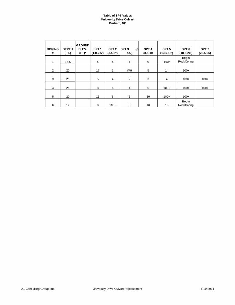
Table of SPT Values
University Drive Culvert
Durham, NC
BORING
#
DEPTH
(FT.)
GROUND
ELEV.
(FT)*
SPT 1
(1.0-2.5')
SPT 2
(3.5-5'')
SPT 3 (6-
7.5')
SPT 4
(8.5-10
SPT 5
(13.5-15')
SPT 6
(18.5-20')
SPT 7
(23.5-25)
1 15.5 4 4 4 9 100*
Begin
RockCoring
2 20 17 1 WH 5 14 100+
3 25 5 4 2 3 4 100+ 100+
4 25 8 6 4 5 100+ 100+ 100+
5 20 13 8 8 30 100+ 100+
6 17 8 100+ 8 10 18
Begin
RockCoring
A1 Consulting Group, Inc. University Drive Culvert Replacement 8/10/2011
Page 37
A1 Consulting Group, Inc. Phone:(919) 469 4800
117 International Dr. Fax:(919) 319 8400
Morrisville, NC 27560
SIEVE ANALYSIS
Project # Date: 8/1/2011
Project Name: Depth: 6.0-7.5
Sample # Tested by: Bill Boyd
Weight of Checked by: V. Goel
Oven-dried sample(gms)
# Sieve Size Sieve Size Weight Retained Weight Passed Total Percent
(mm)
1 3/8 in 9.5 100.0 100.0
2 No. 4 4.75 0 100.0 100.0
3 No. 10 2 0 100.0 100.0
4 No. 40 0.425 4.2 95.8 95.8
5 No. 60 0.25 7.8 88.0 88.0
6 No. 100 0.15 16.2 71.8 71.8
7 No. 200 0.075 21.3 50.5 50.5
8 No. 270 0.053 10.3 40.2 40.2
0.041 29.0
0.029 24.0
0.019 (Hydrometer Values) 18.5
0.011 14.0
0.0081 12.5
0.0058 11.0
0.0029 8.5
0.0012 6.0
Liquid Limit: 20
Plastic Index: NP
USCS Classification: ML
sandy silt
100
10-070
University Drive Culvert Replacement
B1 S3
0.0
10.0
20.0
30.0
40.0
50.0
60.0
70.0
80.0
90.0
100.0
0.0010.010.1110
Pe
rce
nt
Fin
er
Th
an
Particle Size (mm)
B1 S3
Page 38
A1 Consulting Group, Inc. Phone:(919) 469 4800
117 International Dr. Fax:(919) 319 8400
Morrisville, NC 27560
SIEVE ANALYSIS
Project # Date: 8/1/2011
Project Name: Depth: 6.0-7.5
Sample # Tested by: Bill Boyd
Weight of Checked by: V. Goel
Oven-dried sample(gms)
# Sieve Size Sieve Size Weight Retained Weight Passed Total Percent
(mm)
1 3/8 in 9.5 100.0 100.0
2 No. 4 4.75 0 100.0 100.0
3 No. 10 2 0.5 99.5 99.5
4 No. 40 0.425 12.7 86.8 86.8
5 No. 60 0.25 13 73.8 73.8
6 No. 100 0.15 13.7 60.1 60.1
7 No. 200 0.075 12.6 47.5 47.5
8 No. 270 0.053 5.7 41.8 41.8
0.041 31.0
0.029 29.0
0.019 (Hydrometer Values) 23.5
0.011 21.0
0.0081 20.0
0.0058 18.0
0.0029 14.0
0.0012 11.0
Liquid Limit: 23
Plastic Index: 5
USCS Classification: SC-SM
clayey silty sand
100
10-070
University Drive Culvert Replacement
B3 S3
0.0
10.0
20.0
30.0
40.0
50.0
60.0
70.0
80.0
90.0
100.0
0.0010.010.1110
Pe
rce
nt
Fin
er
Th
an
Particle Size (mm)
B3 S3
Page 39
A1 Consulting Group, Inc. Phone:(919) 469 4800
117 International Dr. Fax:(919) 319 8400
Morrisville, NC 27560
SIEVE ANALYSIS
Project # Date: 8/1/2011
Project Name: Depth: 13.5-15.0
Sample # Tested by: Bill Boyd
Weight of Checked by: V. Goel
Oven-dried sample(gms)
# Sieve Size Sieve Size Weight Retained Weight Passed Total Percent
(mm)
1 3/8 in 9.5 50.0 100.0
2 No. 4 4.75 0 50.0 100.0
3 No. 10 2 0 50.0 100.0
4 No. 40 0.425 0.1 49.9 99.8
5 No. 60 0.25 0.6 49.3 98.6
6 No. 100 0.15 11.3 38.0 76.0
7 No. 200 0.075 17.5 20.5 41.0
8 No. 270 0.053 4.0 16.5 33.0
0.047 24.0
0.033 19.0
0.021 (Hydrometer Values) 16.0
0.012 14.0
0.008 10.0
0.0063 9.0
0.0031 3.0
0.0013 0.0
Liquid Limit: 26
Plastic Index: 9
USCS Classification: SM
silty sand
50
10-070
University Drive Culvert Replacement
B5 S4
0.0
10.0
20.0
30.0
40.0
50.0
60.0
70.0
80.0
90.0
100.0
0.0010.010.1110
Pe
rce
nt
Fin
er
Th
an
Particle Size (mm)
B5 S4
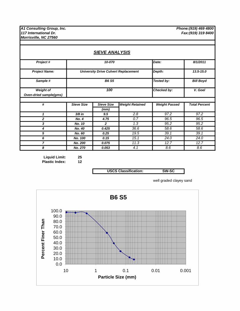
Page 40
A1 Consulting Group, Inc. Phone:(919) 469 4800
117 International Dr. Fax:(919) 319 8400
Morrisville, NC 27560
SIEVE ANALYSIS
Project # Date: 8/1/2011
Project Name: Depth: 13.5-15.0
Sample # Tested by: Bill Boyd
Weight of Checked by: V. Goel
Oven-dried sample(gms)
# Sieve Size Sieve Size Weight Retained Weight Passed Total Percent
(mm)
1 3/8 in 9.5 2.8 97.2 97.2
2 No. 4 4.75 0.7 96.5 96.5
3 No. 10 2 1.3 95.2 95.2
4 No. 40 0.425 36.6 58.6 58.6
5 No. 60 0.25 19.5 39.1 39.1
6 No. 100 0.15 15.1 24.0 24.0
7 No. 200 0.075 11.3 12.7 12.7
8 No. 270 0.053 4.1 8.6 8.6
Liquid Limit: 25
Plastic Index: 12
USCS Classification: SW-SC
well graded clayey sand
10-070
University Drive Culvert Replacement
B6 S5
100
0.0
10.0
20.0
30.0
40.0
50.0
60.0
70.0
80.0
90.0
100.0
0.0010.010.1110
Pe
rce
nt
Fin
er
Th
an
Particle Size (mm)
B6 S5
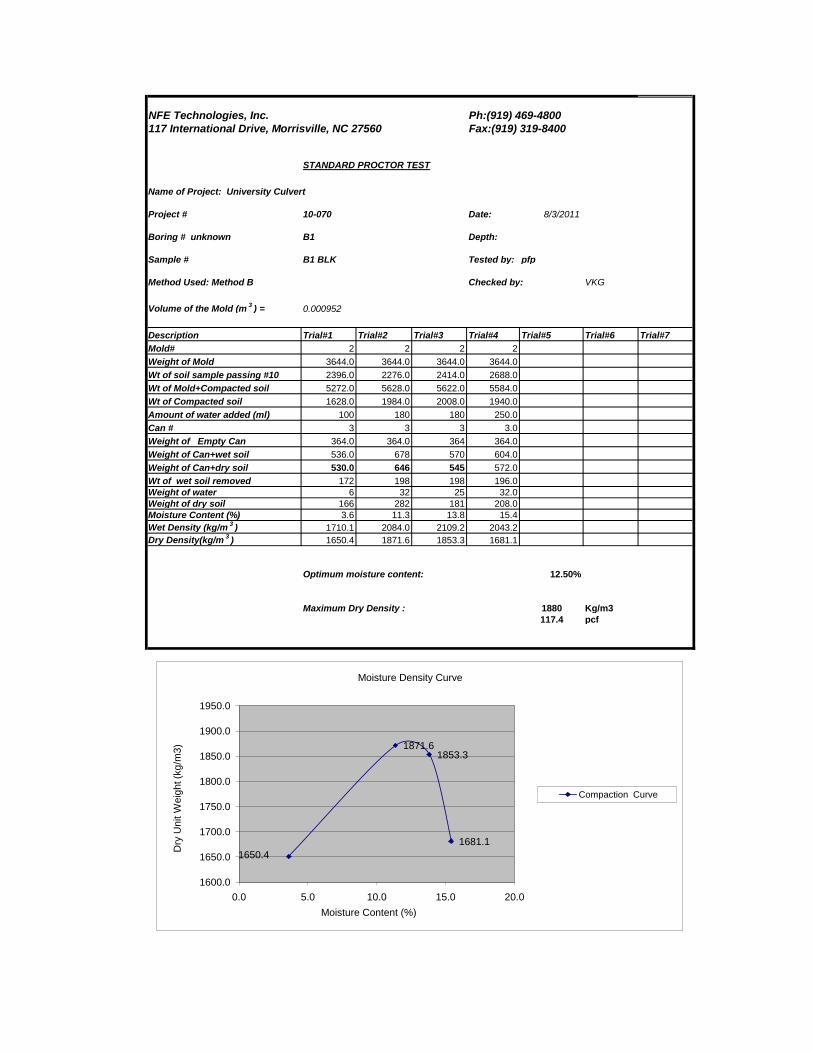
Page 41
NFE Technologies, Inc. Ph:(919) 469-4800
117 International Drive, Morrisville, NC 27560 Fax:(919) 319-8400
STANDARD PROCTOR TEST
Name of Project: University Culvert
Project # 10-070 Date: 8/3/2011
Boring # unknown B1 Depth:
Sample # B1 BLK Tested by: pfp
Method Used: Method B Checked by: VKG
Volume of the Mold (m3) = 0.000952
Description Trial#1 Trial#2 Trial#3 Trial#4 Trial#5 Trial#6 Trial#7
Mold# 2 2 2 2
Weight of Mold 3644.0 3644.0 3644.0 3644.0
Wt of soil sample passing #10 2396.0 2276.0 2414.0 2688.0
Wt of Mold+Compacted soil 5272.0 5628.0 5622.0 5584.0
Wt of Compacted soil 1628.0 1984.0 2008.0 1940.0
Amount of water added (ml) 100 180 180 250.0
Can # 3 3 3 3.0
Weight of Empty Can 364.0 364.0 364 364.0
Weight of Can+wet soil 536.0 678 570 604.0
Weight of Can+dry soil 530.0 646 545 572.0
Wt of wet soil removed 172 198 198 196.0
Weight of water 6 32 25 32.0
Weight of dry soil 166 282 181 208.0
Moisture Content (%) 3.6 11.3 13.8 15.4
Wet Density (kg/m3) 1710.1 2084.0 2109.2 2043.2
Dry Density(kg/m3) 1650.4 1871.6 1853.3 1681.1
Optimum moisture content: 12.50%
Maximum Dry Density : 1880 Kg/m3
117.4 pcf
1650.4
1871.61853.3
1681.1
1600.0
1650.0
1700.0
1750.0
1800.0
1850.0
1900.0
1950.0
0.0 5.0 10.0 15.0 20.0
Dry
Un
it W
eig
ht (k
g/m
3)
Moisture Content (%)
Moisture Density Curve
Compaction Curve
Page 42
NFE Technologies, Inc. Ph:(919) 469-4800
117 International Drive, Morrisville, NC 27560 Fax:(919) 319-8400
STANDARD PROCTOR TEST
Name of Project: University Culvert
Project # 10-070 Date: 8/3/2011
Boring # B3A Depth:
Sample # B3A BLK Tested by: pfp
Method Used: Method B Checked by: VKG
Volume of the Mold (m3) = 0.000952
Description Trial#1 Trial#2 Trial#3 Trial#4 Trial#5 Trial#6 Trial#7
Mold# 2 2 2
Weight of Mold 3644.0 3644.0 3644.0
Wt of soil sample passing #10 2082.0 2414.0 2688.0
Wt of Mold+Compacted soil 5620.0 5674.0 5660.0
Wt of Compacted soil 1976.0 2030.0 2016.0
Amount of water added (ml) 100 180 250
Can # 3 3 3
Weight of Empty Can 364.0 364.0 364
Weight of Can+wet soil 522.0 606 600
Weight of Can+dry soil 510.0 586 576
Wt of wet soil removed 158 198 196
Weight of water 12 20 24
Weight of dry soil 146 222 212
Moisture Content (%) 8.2 9.0 11.3
Wet Density (kg/m3) 2075.6 2132.4 2117.6
Dry Density(kg/m3) 1918.0 1956.1 1902.3
Optimum moisture content: 9.00%
Maximum Dry Density : 1956 Kg/m3
122.1 pcf
1918.0
1956.1
1902.3
1890.0
1900.0
1910.0
1920.0
1930.0
1940.0
1950.0
1960.0
0.0 2.0 4.0 6.0 8.0 10.0 12.0
Dry
Unit W
eig
ht (k
g/m
3)
Moisture Content (%)
Moisture Density Curve
Compaction Curve
Page 43
NFE Technologies, Inc. Ph:(919) 469-4800
117 International Drive, Morrisville, NC 27560 Fax:(919) 319-8400
STANDARD PROCTOR TEST
Name of Project: University Culvert
Project # 10-070 Date: 8/3/2011
Boring # B4 Depth:
Sample # B4 BLK2 Tested by: pfp
Method Used: Method B Checked by: VKG
Volume of the Mold (m3) = 0.000952
Description Trial#1 Trial#2 Trial#3 Trial#4 Trial#5 Trial#6 Trial#7
Mold# 2 2 2 2
Weight of Mold 3644.0 3644.0 3644.0 3644.0
Wt of soil sample passing #10 2396.0 2414.0 2414.0 2688.0
Wt of Mold+Compacted soil 5532.0 5584.0 5652.0 5662.0
Wt of Compacted soil 1888.0 1940.0 2008.0 2018.0
Amount of water added (ml) 100 180 180 250.0
Can # 3 3 3 3.0
Weight of Empty Can 364.0 364.0 364 364.0
Weight of Can+wet soil 650.0 570 570 604.0
Weight of Can+dry soil 626.0 550 548 572.0
Wt of wet soil removed 286 198 198 196.0
Weight of water 24 20 22 32.0
Weight of dry soil 262 186 184 208.0
Moisture Content (%) 9.2 10.8 12.0 15.4
Wet Density (kg/m3) 1983.2 2037.8 2109.2 2119.7
Dry Density(kg/m3) 1816.8 1840.0 1884.0 1837.1
Optimum moisture content: 12.00%
Maximum Dry Density : 1884 Kg/m3
117.6 pcf
1816.8
1840.0
1884.0
1837.1
1810.0
1820.0
1830.0
1840.0
1850.0
1860.0
1870.0
1880.0
1890.0
0.0 5.0 10.0 15.0 20.0
Dry
Unit W
eig
ht (k
g/m
3)
Moisture Content (%)
Moisture Density Curve
Compaction Curve
Page 44
A1 Consulting Group, Inc. Phone:(919)469-4800
117 International Drive, Fax:(919)319-8400
Morrisville, NC 27560
DETERMINATION OF SOIL RESISTIVITY
Project # 10-070 Date 8/2/2011
Boring # B1 Depth 10-15'
Total Dry 1500 Tested by HWB
Sample Wt.(g)
Checked by VKG
# Water Temp Can # Wt of Wt of can+ Wt of can+ Wt of Wt of Moisture Resistivity
Quantity(ml) °C Can (g) Wet soil(g) Dry soil(g) Water(g) Soil (g) Content (%) k ohm .cm
1 75 28 29 29.8 157.3 117.2 40.1 87.4 6 12000
2 50 28 8 30.9 146.9 139.1 7.8 108.2 10 6400
3 50 28 25 29.9 155.9 111.3 44.6 81.4 15 4650
4 50 28 44 30.4 174.4 134.9 39.5 104.5 20 5250
5
6
7
8
9
10
11
12
13
14
B1
Minimun Soil Resistivity 4650
Maximum Soil Moisture 16%
0
2000
4000
6000
8000
10000
12000
14000
0 5 10 15 20 25
res
isti
vit
y (
ko
hm
cm
)
moisture (%)
Soil Resistivity
Series1
A1 Consulting Group, Inc. 8/10/2011
Page 45
A1 Consulting Group, Inc. Phone:(919)469-4800
117 International Drive, Fax:(919)319-8400
Morrisville, NC 27560
DETERMINATION OF SOIL RESISTIVITY
Project # 10-070 Date 8/2/2011
Boring # B3A Depth 10-15'
Total Dry 1500 Tested by HWB
Sample Wt.(g)
Checked by VKG
# Water Temp Can # Wt of Wt of can+ Wt of can+ Wt of Wt of Moisture Resistivity
Quantity(ml) °C Can (g) Wet soil(g) Dry soil(g) Water(g) Soil (g) Content (%) k ohm .cm
1 50 28 3 31.4 129.9 117.2 12.7 85.8 15 2900
2 75 28 7 31.1 157.9 139.1 18.8 108.0 17 2750
3 100 28 47 30.4 128.0 111.3 16.7 80.9 21 3000
4 50 28 26 29.9 159.7 134.9 24.8 105.0 24 3050
5
6
7
8
9
10
11
12
13
14
B3A
Minimun Soil Resistivity 2750
Maximum Soil Moisture 17%
2700
2750
2800
2850
2900
2950
3000
3050
3100
0 5 10 15 20 25
res
isti
vit
y (
ko
hm
cm
)
moisture (%)
Soil Resistivity
Series1
A1 Consulting Group, Inc. 8/10/2011
Page 46
A1 Consulting Group, Inc. Phone:(919)469-4800
117 International Drive, Fax:(919)319-8400
Morrisville, NC 27560
DETERMINATION OF SOIL RESISTIVITY
Project # 10-070 Date 8/3/2011
Boring # B4 Depth 10-15'
Total Dry 1500 Tested by HWB
Sample Wt.(g)
Checked by VKG
# Water Temp Can # Wt of Wt of can+ Wt of can+ Wt of Wt of Moisture Resistivity
Quantity(ml) °C Can (g) Wet soil(g) Dry soil(g) Water(g) Soil (g) Content (%) k ohm .cm
1 100 28 41 30.6 135.9 126.4 9.5 95.8 10 6350
2 50 28 45 30.3 147.8 133.6 14.2 103.3 14 3200
3 50 28 18 31.1 144.7 127.7 17.0 96.6 18 3450
4
5
6
7
8
9
10
11
12
13
14
B4
Minimun Soil Resistivity 3000
Maximum Soil Moisture 15%
0
1000
2000
3000
4000
5000
6000
7000
0 5 10 15 20
res
isti
vit
y (
ko
hm
cm
)
moisture (%)
Soil Resistivity
Series1
A1 Consulting Group, Inc. 8/10/2011
Page 47
A1 Consulting Group, Inc. Phone:(919)4694800
117 International Drive, Fax:(919)3198400
Morrisville, NC 27560
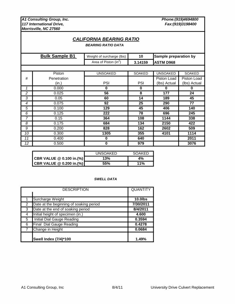
CALIFORNIA BEARING RATIO
BEARING RATIO DATA
Bulk Sample B1 Weight of surcharge (lbs) 10 Sample preparation by
Area of Piston (in2) 3.14159 ASTM D968
Piston UNSOAKED SOAKED UNSOAKED SOAKED
# Penetration Piston Load Piston Load
(in.) PSI PSI (lbs) Actual (lbs) Actual
1 0.000 0 0 0 0
2 0.025 56 8 177 24
3 0.05 60 14 189 45
4 0.075 92 25 290 77
5 0.100 129 45 406 140
6 0.125 222 78 696 245
7 0.15 364 108 1144 338
8 0.175 684 134 2150 422
9 0.200 828 162 2602 509
10 0.300 1305 355 4101 1114
11 0.400 0 640 2011
12 0.500 0 979 3076
UNSOAKED SOAKED
CBR VALUE @ 0.100 in.(%) 13% 4%
CBR VALUE @ 0.200 in.(%) 55% 11%
SWELL DATA
DESCRIPTION QUANTITY
1 Surcharge Weight 10.0lbs
2 Date at the beginning of soaking period 7/30/2011
3 Date at the end of soaking period 8/4/2011
4 Initial height of specimen (in.) 4.600
5 Initial Dial Gauge Reading 0.3594
6 Final Dial Gauge Reading 0.4278
7 Change in Height 0.0684
Swell Index (7/4)*100 1.49%
A1 Consulting Group, Inc 8/4/11 University Drive Culvert Replacement
Page 48
0
200
400
600
800
1000
1200
1400
0.000 0.050 0.100 0.150 0.200 0.250 0.300 0.350
Lo
ad
(lb
.)
Penetration (in.)
CBR Bearing DataB1
Series1 Series2
Page 49
A1 Consulting Group, Inc. Phone:(919)4694800
117 International Drive, Fax:(919)3198400
Morrisville, NC 27560
CALIFORNIA BEARING RATIO
BEARING RATIO DATA
Bulk Sample B6 Weight of surcharge (lbs) 10 Sample preparation by
Area of Piston (in2) 3.14159 ASTM D968
Piston UNSOAKED SOAKED UNSOAKED SOAKED
# Penetration Piston Load Piston Load
(in.) PSI PSI (lbs) Actual (lbs) Actual
1 0.000 0 0 0 0
2 0.025 37 6 115 18
3 0.05 56 17 175 53
4 0.075 86 38 270 118
5 0.100 124 65 388 205
6 0.125 148 97 466 306
7 0.15 282 123 886 385
8 0.175 449 151 1410 473
9 0.200 664 174 2086 546
10 0.300 1227 350 3856 1101
11 0.400 0 0
12 0.500 0 0
UNSOAKED SOAKED
CBR VALUE @ 0.100 in.(%) 12% 7%
CBR VALUE @ 0.200 in.(%) 44% 12%
SWELL DATA
DESCRIPTION QUANTITY
1 Surcharge Weight 10.0lbs
2 Date at the beginning of soaking period 7/30/2011
3 Date at the end of soaking period 8/4/2011
4 Initial height of specimen (in.) 4.600
5 Initial Dial Gauge Reading 0.103
6 Final Dial Gauge Reading 0.112
7 Change in Height 0.009
Swell Index (7/4)*100 0.20%
A1 Consulting Group, Inc 8/4/11 University Drive Culvert Replacement
Page 50
0
200
400
600
800
1000
1200
1400
0.000 0.050 0.100 0.150 0.200 0.250 0.300 0.350
Lo
ad
(lb
.)
Penetration (in.)
CBR Bearing DataB5
Series1 Series2
Page 51
SOIL CLASSIFICATION CHART
SW
SP
SM
SC
ML
CL
MH
CH
MLS
CLS
ML-CL
PWR
PWR
Rock
WELL GRADED SANDS, GRAVELLY SANDS, LITTLE OR NO
FINES
POORLY-GRADED SANDS, GRAVELLY SAND, LITTLE OR
NO FINES
SILTY SAND, SAND - SILT MIXTURES
PARTIALLY WEATHERED ROCK
ROCK
MIXTURE OF CLAY AND SAND
MIXTURE OF SILT AND CLAY
CLAYEY SANDS, SAND - CLAY MIXTURES
INORGANIC SILTS AND VERY FINE SANDS, ROCK FLOUR,
SILTY OR CLAYEY FINE SANDS OR CLAYEY SILTS WITH
SLIGHT PLASTICITY
INORGANIC CLAYS OF LOW TO MEDIUM PLASTICITY,
GRAVELLY CLAYS, SANDY CLAYS, SILTY CLAYS, LEANS
CLAYS
INORGANIC SILTS, MICACEOUS OR DIATOMACEOUS
FINE SAND OR SILTY SOILS
INORGANIC CLAYS OF HIGH PLASTICITY
MIXTURE OF SILT AND SAND
A1 Consulting Group, Inc 117 International Drive
Morrisville, NC 27560
Phone (919) 469-4800
Fax (919) 319-8400
Page 52
A1 Consulting Group, Inc.Consulting Engineers
BORING LOG 117 International Drive
Morrisville, NC 27560
(919) 469-4800
Project Name: Durham University Drive Culvert Boring Number: B1
Boring Location: Grass beside road, near culvert outlet Collar elevation: ~ 303 feet
Date Started: July 21, 2011 Total Depth of Boring (ft): 15.5
Date Completed: July 21, 2011 Depth to Groundwater (ft) : .
Drill Rig Type: CME 75 Depth to Groundwater (ft) -24 hr. .
Hammer Type: 63.5 kg hammer
Driller's Name: Mario A1 Geologist/Engineer: B. Boyd .
Drilling Method: 3.75 inch (Hollow Stem Auger)
Blow Counts
Elevation
(ft)
Depth
(ft) 6 in. 6 in. 6 in. N
Sample
# MoistureRecovery
% Log Description
303 0.0 2" grass, topsoil
302.5 0.5 3 2 3 5 1 Moist 100
1.0
1.5
2.0
2.5
3.0
299.5 3.5 2 3 2 5 2 Wet 100
4.0
4.5
5.0
5.5
297 6.0 2 1 2 3 3 S 100
6.5
7.0
7.5
8.0
8.5
9.0
293.5 9.5 2 2 6 8 4 Wet 100
10.0
10.5
11.0
11.5
12.0
12.5
290 13.0 9 50/2" 100+
13.5
14.0
14.5
15.0
15.5
287 16.0
16.5
17.0
17.5
18.0
18.5
19.0
19.5
20.0
20.5
21.0
21.5
Drilling tereminated at: Auger Refusal / Predetermined depth: 15.5 feet
Rock
Brown/Gray mottled mixed fill with
mica; samples as silty sand
PWR
Gray silty medium sand with mica
Same as above; (all fill to 10')
Brown/Orange mottle PWR sampling
as silty fine sand; Very hard drilling
@ 15'; refusal 15.5'
Same as above
Technical/templates/boring log-master
Page 53
A1 Consulting Group, Inc.Consulting Engineers
BORING LOG 117 International Drive
Morrisville, NC 27560
(919) 469-4800
Project Name: Durham University Drive Culvert Boring Number: B2
Boring Location: Road Collar elevation: ~ 306 feet
Date Started: July 20, 2011 Total Depth of Boring (ft): 20
Date Completed: July 20, 2011 Depth to Groundwater (ft) : .
Drill Rig Type: CME 75 Depth to Groundwater (ft) -24 hr. .
Hammer Type: 63.5 kg hammer
Driller's Name: Mario A1 Geologist/Engineer: B. Boyd .
Drilling Method: 3.75 inch (Hollow Stem Auger)
Blow Counts
Elevation
(ft)
Depth
(ft) 6 in. 6 in. 6 in. N
Sample
# MoistureRecovery
% Log Description
306 0.0 4" asphalt
305.5 0.5 2 4 16 20 1 Moist 100
1.0
1.5
2.0
2.5
3.0
302.5 3.5 1 1 0 1 2 Wet 50
4.0
4.5
5.0
5.5
3 6.0 WH 3 Wet 30
6.5
7.0
7.5
8.0
297.5 8.5 4 3 2 5 4 Wet 100
9.0
9.5
10.0
10.5
11.0
11.5
12.0
12.5
13.0
292.5 13.5 3 3 10 13 5 Moist 100
14.0
14.5
15.0
15.5
16.0
16.5
17.0
17.5
18.0
287.5 18.5 50/4" 6 Dry 100
19.0
19.5
20.0
Drilling tereminated at: Auger Refusal / Predetermined depth: 20 feet
6" gray dry fine sand
Orange / black mottled (fill) sandy silt
Gray/ Brown silt (fill)
Same as above
Same as above
3" saturated sand; 15" brown / black
mottled sandy silt
Technical/templates/boring log-master
Page 54
A1 Consulting Group, Inc.Consulting Engineers
BORING LOG 117 International Drive
Morrisville, NC 27560
(919) 469-4800
Project Name: Durham University Drive Culvert Boring Number: B3
Boring Location: Front Parking Lot Collar elevation: ~ 308 feet
Date Started: July 20, 2011 Total Depth of Boring (ft): 25
Date Completed: July 20, 2011 Depth to Groundwater (ft) : .
Drill Rig Type: CME 75 Depth to Groundwater (ft) -24 hr. .
Hammer Type: 63.5 kg hammer
Driller's Name: Mario A1 Geologist/Engineer: B. Boyd .
Drilling Method: 3.75 inch (Hollow Stem Auger)
Blow Counts
Elevation
(ft)
Depth
(ft) 6 in. 6 in. 6 in. N
Sample
# MoistureRecovery
% Log Description
308 0.0 1" asphalt; 3" concrete
307.5 0.5 2 2 2 4 1 Moist 100
1.0
1.5
2.0
2.5
3.0
304.5 3.5 2 1 3 4 2 Wet 100
4.0
4.5
5.0
5.5
302 6.0 1 1 1 2 3 Wet 100
6.5
7.0
7.5
8.0
299.5 8.5 2 1 2 3 4 Wet 100
9.0
9.5
10.0
10.5
11.0
11.5
12.0
12.5
13.0
294.5 13.5 2 2 2 4 5 Moist 100
14.0
14.5
15.0
15.5
16.0
16.5
17.0
17.5
18.0
289.5 18.5 50/6" 6 Moist 100
19.0
19.5
20.0
20.5
21.0
22.0
22.5
285 23.0 50/3"
23.5
24.0
24.5
25.0
Drilling tereminated at: Auger Refusal / Predetermined depth: 25 feet
Same as above
Gray silty sand with mica
Brown silty sand with mica
Same as above
Brown clay sand with mica; plastic
Gray sandy clay plastic; minor fine
mica
Gray silty sand, non plastic;
saturated mud to 17'; harder drilling
Technical/templates/boring log-master
Page 55
A1 Consulting Group, Inc.Consulting Engineers
BORING LOG 117 International Drive
Morrisville, NC 27560
(919) 469-4800
Project Name: Durham University Drive Culvert Boring Number: B4
Boring Location: Side Parking Lot Collar elevation: ~ 310 feet
Date Started: July 20, 2011 Total Depth of Boring (ft): 25
Date Completed: July 20, 2011 Depth to Groundwater (ft) : dry .
Drill Rig Type: CME 75 Depth to Groundwater (ft) -24 hr. 8.4' .
Hammer Type: 63.5 kg hammer
Driller's Name: Mario A1 Geologist/Engineer: B. Boyd .
Drilling Method: 3.75 inch (Hollow Stem Auger)
Blow Counts
Elevation
(ft)
Depth
(ft) 6 in. 6 in. 6 in. NSample
# MoistureRecovery
% Log Description
310 0.0
0.5
309 1.0 3 4 4 8 1 Moist 100
1.5
2.0
2.5
3.0
306.5 3.5 3 2 3 5 2 Moist 100
4.0
4.5
5.0
5.5
304 6.0 1 2 2 4 3 Moist 100
6.5
7.0
7.5
8.0
301.5 8.5 2 2 2 4 4 Moist 100
9.0
9.5
10.0
10.5
11.0
11.5
12.0
12.5
13.0
296.5 13.5 50/4" 100+ 5 Dry 100
14.0
14.5
15.0
15.5
16.0
16.5
17.0
17.5
18.0
291.5 18.5 50/3" 6 Dry 100
19.0
19.5
20.0
20.5
21.0
22.0
22.5
287 23.0 50/2" 7 Dry 100
23.5
24.0
24.5
25.0
Drilling tereminated at: Auger Refusal / Predetermined depth: 25 feet
Silty clay sand with mica 13'; harder
drilling
Gray silty sand with mica - friable
Same as above; Refusal broke
machine in attempt to advance
Gray / Black silty sand with mica
friable; very hard drilling
6" concrete; 2" stone
Brown silty sand - fill
Brown gray silty sand - fill
Dry sand with mica
Technical/templates/boring log-master
Page 56
A1 Consulting Group, Inc.Consulting Engineers
BORING LOG 117 International Drive
Morrisville, NC 27560
(919) 469-4800
Project Name: Durham University Drive Culvert Boring Number: B5
Boring Location: Parking Lot Near Dumpsters Collar elevation: ~ 314 feet
Date Started: July 20, 2011 Total Depth of Boring (ft): 20
Date Completed: July 20, 2011 Depth to Groundwater (ft) : dry .
Drill Rig Type: CME 75 Depth to Groundwater (ft) -24 hr. 12' .
Hammer Type: 63.5 kg hammer
Driller's Name: Lee A1 Geologist/Engineer: B. Boyd .
Drilling Method: 3.75 inch (Hollow Stem Auger)
Blow Counts
Elevation
(ft)
Depth
(ft) 6 in. 6 in. 6 in. N
Sample
# MoistureRecovery
% Log Description
314 0.0
0.5
313 1.0 7 7 6 13 1 Dry 100
1.5
2.0
2.5
3.0
310.5 3.5 6 8 6 14 2 Dry 100
4.0
4.5
5.0
5.5
308 6.0 5 8 9 17 3 Dry 100
6.5
7.0
7.5
8.0
305.5 8.5 17 30 50 80 4 Dry 100
9.0
9.5
10.0
10.5
11.0
11.5
12.0
12.5
13.0
300.5 13.5 50/4" 5 Dry 100
14.0
14.5
15.0
15.5
16.0
16.5
17.0
17.5
18.0
295.5 18.5 50/3" 6 Dry 100
19.0
19.5
20.0
Drilling tereminated at: Auger Refusal / Predetermined depth: 20 feet
Same as above; very hard, friable
Partially weathered rock sampling as
silty fine sand
8" concrete
Brown fill - silty sand with mica
Same as above
Brown / Orange silty sand with mica
Hard friable gray silty sand w mica
PWR
Technical/templates/boring log-master
Page 57
A1 Consulting Group, Inc.Consulting Engineers
BORING LOG 117 International Drive
Morrisville, NC 27560
(919) 469-4800
Project Name: Durham University Drive Culvert Boring Number: B6
Boring Location: Rear Parking Lot @ Culvert Collar elevation: ~ 314 feet
Date Started: July 21, 2011 Total Depth of Boring (ft): 17
Date Completed: July 21, 2011 Depth to Groundwater (ft) : 13 .
Drill Rig Type: CME 75 Depth to Groundwater (ft) -24 hr. 12' .
Hammer Type: 63.5 kg hammer
Driller's Name: Lee A1 Geologist/Engineer: B. Boyd .
Drilling Method: 3.75 inch (Hollow Stem Auger)
Blow Counts
Elevation
(ft)
Depth
(ft) 6 in. 6 in. 6 in. N
Sample
# MoistureRecovery
% Log Description
314 0.0 6" concrete
313.5 0.5 4 4 3 7 1 Moist 100
1.0
1.5
2.0
2.5
3.0
310.5 3.5 50/2" Dry 100
4.0
4.5
5.0
5.5
308 6.0 2 2 1 3 3 Wet 100
6.5
7.0
7.5
8.0
305.5 8.5 2 3 4 7 4 Wet 100
9.0
9.5
10.0
10.5
11.0
11.5
12.0
12.5
13.0
300.5 13.5 6 10 9 19 5 Wet 100
14.0
14.5
15.0
15.5
16.0
16.5
17.0
296.5 17.5
18.0
18.5
19.0
19.5
20.0
20.5
21.0
21.5
22.0
Drilling tereminated at: Auger Refusal / Predetermined depth: 17 feet
Rock
Brown / gray clayey sand mixed cse
and fine plastic; 17' hard rock - auger
refusal
Brown mixed fill- sand silt with mica
Gray concrete (?), slighty silty sand
with stones
Brown sandy silt plastic minor mica
Brown sandy clay, plastic abundant
fine mica
Technical/templates/boring log-master
Page 58
Subsurface Conditions That May Impact Construction
316 316
315 315
B6 B5
314 314
7
313 13 313
312 312
311 311
100+ 14 B4
310 310
309 8 309
B3
308 3 17 308
4
307 307
5
306 306
7 80
305 305
4
304 4 304
B1
303 303
5
302 2 302
4
301 301
19 100+
300 300
3 5
299 299
Inferrred Water
298 Table 298
297 100+ 3 297
100+
296 296
100+
295 295
4
294 294
8
293 293
292 292
100+
291 291
290 100+ 290
100+
289 289
288 288
100+
287 287
286 286
100+
285 285
284 284
283 283
282 282
B6 B5 B4 B3 B1
Brackets Indicate Weak Soil Groundwater
Ele
vati
on
(ft
)
Boring Number
PWR
*Distances Not to Scale*
PWR
Top of Culvert
Bottom of Culvert
A1 Consulting Group, Inc University Drive Culvert Replacement 8/15/2011
Page 59
Rock Core B6
Run: 5’ Recovery: 85% RQD: 67.5% (fair rock)
Coring began at a depth of 17’
At the top of the core there is approximately 6” of river jack – rounded stream cobbles.
Sue to the nature of the material it the exact length of core containing river jack cannot
be determined.
Below the river jack is 35” continuous of gray fine to medium grain sound sandstone.
There are no obvious joints or fractures.
After a break there is another 10.5” of the same material.
top 6” 35” 10.5” end
river jack sandstone sandstone
Page 60
Rock Core B1
Run: 5’ Recovery: 80% RQD: 63% (fair rock)
Coring began at depth of 15.5’
At the top there is 15” of sound fine/medium grain sandstone with no obvious joints or
fractures. Fracture occurs at change in composition.
Below the fracture there is 2” dark gray sandstone, ½” of the same, then 2” sandstone
with vugs and non-displaced vertical fractures.
Below this is a 6” gap.
Below the gap begins 7” of brown siltstone with horizontal bedding and evidence of
healed horizontal fractures and filled vugs.
Another 6” gap.
Below the second gap is 10” of brown siltstone with low angle fractures, 3 of which have
no displacement. At the bottom of this section is a fracture and an approximately ½”
section of the same material.
The core ends with 9” of brown siltstone with 1 displaced fracture.
top 15” 2” ½” 2” 6” 7” 6” 10” ½” 9” 1” end
sandstone gap siltstone gap fractured siltstone
siltstone
Page 62
A1 Consulting Group, Inc117 International DriveMorrisville, NC 27560