+ All Categories
Home > Documents > Report on the seismic reinforcement work of Sagamihara ... · Report on the seismic reinforcement...

Report on the seismic reinforcement work of Sagamihara ... · Report on the seismic reinforcement...

Date post: 30-Apr-2019
Category:
Upload: tranthien
View: 215 times
Download: 0 times
Share this document with a friend
10
Report on the seismic reinforcement work of Sagamihara Sedimentation Basin Construction Section, Facilities Department, Yokohama Water Works Bureau SUZUKI, Tomomi Abstract Sagamihara Sedimentation Basin is a structure of the earth-fill dam type for removing suspended solids in raw water via deposition. In FY 2011, the bank was inspected for seismic resistance. The inspection showed that the main bank lacked the required seismic resistance on the side facing the basin (referred to as the “upstream face”). By considering constraints on construction, etc., the basin was decided to be seismically retrofitted by replacing the outside part (referred to as the “downstream face”) of the bank with reinforced embankment of soil cement. 1. INTRODUCTION Yokohama Water Works Bureau supplies a daily average of approximately 1.15 million m 3 of drinking water to approximately 3.7 million citizens. Since the establishment of waterworks in 1887, the Bureau has expanded its facilities eight times in order to respond to population growth and the expansion of the urban areas. Today, the facilities are being improved on seismic resistance and water treatment functions based on the “Long-term vision and 10-year plan”, which was formulated in 2006. This paper is a report on the seismic reinforcement work on the main bank of Sagamihara Sedimentation Basin. Fig. 1.1 An entire view of Sagamihara Sedimentation Basin
Transcript

Report on the seismic reinforcement work of

Sagamihara Sedimentation Basin Construction Section, Facilities Department, Yokohama Water Works Bureau

SUZUKI, Tomomi

Abstract

Sagamihara Sedimentation Basin is a structure of the earth-fill dam type for removing

suspended solids in raw water via deposition. In FY 2011, the bank was inspected for

seismic resistance. The inspection showed that the main bank lacked the required

seismic resistance on the side facing the basin (referred to as the “upstream face”).

By considering constraints on construction, etc., the basin was decided to be seismically

retrofitted by replacing the outside part (referred to as the “downstream face”) of the

bank with reinforced embankment of soil cement.

1. INTRODUCTION

Yokohama Water Works Bureau

supplies a daily average of

approximately 1.15 million m3 of

drinking water to approximately 3.7

million citizens.

Since the establishment of waterworks

in 1887, the Bureau has expanded its

facilities eight times in order to

respond to population growth and the

expansion of the urban areas. Today,

the facilities are being improved on

seismic resistance and water treatment

functions based on the “Long-term vision and 10-year plan”, which was formulated in

2006.

This paper is a report on the seismic reinforcement work on the main bank of

Sagamihara Sedimentation Basin.

Fig. 1.1 An entire view of Sagamihara

Sedimentation Basin

2. OVERVIEW OF SAGAMIHARA SEDIMENTATION BASIN

Sagamihara Sedimentation Basin was constructed in 1954 by making use of the natural

landform. This basin is located between Lake Sagami, which is one of water resources

of Yokohama City, and Nishiya water purification plant (Fig. 2.1). Its structure is the

earth-fill dam type. (Fig.2.2 and 2.3) It can store 883,000 m3 of water as emergency

water storage and remove suspended solids in raw water via deposition. In case that the

turbidity of the raw water becomes high such as during a typhoon or storm, the

sedimentation is accelerated by adding PAC (Poly aluminum chloride).

3. CIRCUMSTANCES OF THE SEISMIC RESISTANCE INVESTIGATION

Yokohama Water Works Bureau examined the seismic resistance of Sagamihara

Sedimentation Basin in 1982 and discovered that the slip surface of the downstream

face of the main bank lacked seismic resistance. Therefore, the main bank was

retrofitted by cutting and installing counterweight fill along the downstream face of the

bank (Fig. 3.1). Later, in 1997 and 2009, the Seismic Design Guideline for Water

Works Facilities (hereinafter referred to as the “Guidelines”) was revised requiring for a

raised seismic resistance level. Because there are a university and Sagamihara Park,

which is a governmentally designated evacuation site at the time of disaster, near the

Fig. 2.3 Representative sectional view of Sagamihara Sedimentation Basin

Fig. 2.2 Plan of Sagamihara Sedimentation Basin Fig. 2.1 Locality map of Sagamihara

Sedimentation Basin

Fig. 3.1 Outline map of the retrofit work

basin, collapse of the bank was

feared to lead to secondary

damage and affect people and

properties. A dam which had a

structure similar to that of this

basin collapsed in the Great East

Japan Earthquake. Therefore, the

seismic resistance of the basin was

checked based on the Guidelines (2009). The main bank was found to not have the

required seismic resistance, and retrofit work started in 2013.

4. VERIFICATION OF SEISMIC RESISTANCE

The main bank of Sagamihara Sedimentation Basin is an earth-fill dam structure.

Therefore, the seismic resistance of the main bank was evaluated by referring to the

standards for dams.

The basin is an important facility for lowering the turbidity of water as well as storing

water for emergencies. Therefore, the stability of the main bank against Level 1

earthquake motions was analyzed by using the modified seismic coefficient method,

which is a strict method for evaluating seismic resistance. The standards to conform to

were those of the “Draft of Guidelines for Seismic Design of Embankment Dams”

(1991, Japan Institute of Country-ology and Engineering), which refers to the inspection

of seismic resistance of dams by using the modified seismic coefficient method.

According to the Guidelines (2009), the safety against Level 2 earthquake motions was

analyzed by following the “Guidelines for Seismic Performance Evaluation of Dams

During Large Earthquakes (Draft) and Explanation” (2005, Ministry of Land,

Infrastructure, Transport and Tourism). An overview and the results of the evaluation

are shown in Table 1.

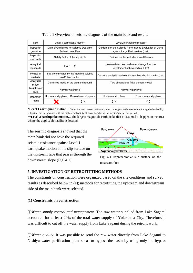
Fig. 4.1 Representative slip surface on the

upstream face

*Level 1 earthquake motion…Out of the earthquakes that are assumed to happen in the area where the applicable facility

is located, the earthquakes with the highest probability of occurring during the facility’s in-service period. **Level 2 earthquake motion…The largest magnitude earthquake that is assumed to happen in the area where the applicable facility is located.

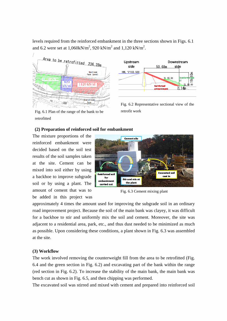
The seismic diagnosis showed that the

main bank did not have the required

seismic resistance against Level 1

earthquake motion at the slip surface on

the upstream face that passes through the

downstream slope (Fig. 4.1).

5. INVESTIGATION OF RETROFITTING METHODS

The constraints on construction were organized based on the site conditions and survey

results as described below in (1); methods for retrofitting the upstream and downstream

side of the main bank were selected.

(1) Constraints on construction

①Water supply control and management. The raw water supplied from Lake Sagami

accounted for at least 20% of the total water supply of Yokohama City. Therefore, it

was difficult to cut off the water supply from Lake Sagami during the retrofit work.

②Water quality. It was possible to send the raw water directly from Lake Sagami to

Nishiya water purification plant so as to bypass the basin by using only the bypass

Table 1 Overview of seismic diagnosis of the main bank and results

Item

Inspectionguideline

Inspectionstandards

Method ofanalysis

Analyticalmodel

Target waterlevel

Upstream slip plane Downstream slip plane Upstream slip plane Downstream slip plane

× ○ ○ ○

Level 1 earthquake motion* Level 2 earthquake motion**

Draft of Guidelines for Seismic Design ofEmbankment Dam

Guideline for the Seismic Performance Evaluation of Damsagainst Large Earthquakes (draft)

Safety factor of the slip circle Residual settlement, elevation difference

No overflow, secured water storage function(settlement not exceeding 1.0m)

Slip circle method by the modified seismiccoefficient method

Analyticalstandards

Fs≧1.2

Inspectionresult

Dynamic analysis by the equivalent linearization method, etc.

Combined model of the dam and ground Two-dimensional finite element model

Normal water level Normal water level

pipeline shown in Fig. 2.3. However, there are no sedimentation facility between

Nishiya Water Purification Plant and Sagamihara Sedimentation basin. This would

lower the performance of water treatment in the event that the turbidity of the raw water

increased, for instance during a typhoon or a storm. Therefore, water could not be sent

solely through the bypass pipeline over a long period of time.

③Ground conditions, etc. When the basin was completed approximately 60 years ago,

cracks developed on the bottom surface of the basin. When the bottom surface was

dried cracks were highly likely to develop again and cause water leakage. Furthermore,

construction of temporary structures that were needed for the retrofit work had risks of

inducing cracks and water leakage.

(2) Plans of retrofitting the upstream face

A common method for retrofitting a slip surface on the upstream face is to retrofit the

edge of the slip surface. Because of the constraints on water supply control and

management mentioned in ①, raw water transmission could not be halted. Therefore

the three methods shown in Table 2 were investigated for retrofitting the upstream side.

Plan A involves emptying the basin and retrofitting the upstream side. As described

above regarding constraints on ground conditions (③), the bottom surface of the basin

was suspected to develop cracks and leak water. To empty the basin, it was necessary to

solely use the bypass pipeline, but water could not be sent solely through the bypass

pipeline over a long period of time as described in the constraints on water quality (②).

Therefore, Plan A was rejected.

Plan B involves closing the area to retrofit by installing a temporary structure such as

steel sheet piles and retrofitting the upstream side. However, as mentioned in the

constraints on ground conditions (③ ), installation of a temporary structure was

suspected to cause cracks on the bottom surface of the basin. Therefore, Plan B was

rejected.

Plan C involves separating the area to retrofit by installing an underwater curtain and

retrofitting the upstream side. However, insertion of the retrofitting materials was

suspected to stir up sediments on the bottom of the basin and deteriorate the quality of

water. Because the plan does not meet the constraints on water quality (②), Plan C was

rejected.

It was thus judged very difficult to retrofit the upstream face.

Table 2 Plans of retrofitting the upstream face

Table 3 Major construction quantities of

the retrofit work

Counterweight fill 14,759m3

Reinforcedembankment 16,759m3

Amount of cementadded(Total)

3,965t

Area to beretrofitted 10,337m2(235m×23~52m)

(3) Plans of retrofitting the downstream face

It was judged difficult to retrofit the slip plane (Fig. 4.1) that did not have the required

safety factor on the upstream side (Plans A, B, and C).

Therefore, a method was investigated

that involved increasing the resistance

of the slip surface on the downstream

face to ensure the required safety

factor (Fig. 5.1).

This method improves the downstream slope where the slip surface passes through,

increases the cohesion and thus enhances the resistance along the slip surface.

The downstream slope was decided to be improved through reinforced embankment by

replacement. The method involves replacing the surface soil of the downstream slope

with reinforced embankment. The uniaxial compressive strength of the reinforced

embankment was increased by mixing cement to the excavated surface soil. The method

has the following advantages among others:

* Work is performed only on the downstream side of the main bank outside the basin;

and thus there are no limitations on water transmission method, such as having to solely

use the bypass pipe, and no deterioration of water quality.

* The depth of improvement is 1 to 2m from the dam surface. Installation of temporary

structures is not required and the materials of the existing bank can be used. Therefore,

the method is economical.

As described, the reinforced embankment by replacement was judged to satisfy the

constraints and to be economical and was thus adopted.

6. RETROFITTING WORKS

(1) Overview of the works

The working area was approximately

10,000m2 on the downstream slope of the

main bank of Sagamihara Sedimentation

Basin. The uniaxial compressive strength

Fig. 5.1 Schematic sectional view of the retrofit plan

Fig. 6.3 Cement mixing plant

levels required from the reinforced embankment in the three sections shown in Figs. 6.1

and 6.2 were set at 1,060kN/m2, 920 kN/m2 and 1,120 kN/m2.

(2) Preparation of reinforced soil for embankment

The mixture proportions of the

reinforced embankment were

decided based on the soil test

results of the soil samples taken

at the site. Cement can be

mixed into soil either by using

a backhoe to improve subgrade

soil or by using a plant. The

amount of cement that was to

be added in this project was

approximately 4 times the amount used for improving the subgrade soil in an ordinary

road improvement project. Because the soil of the main bank was clayey, it was difficult

for a backhoe to stir and uniformly mix the soil and cement. Moreover, the site was

adjacent to a residential area, park, etc., and thus dust needed to be minimized as much

as possible. Upon considering these conditions, a plant shown in Fig. 6.3 was assembled

at the site.

(3) Workflow

The work involved removing the counterweight fill from the area to be retrofitted (Fig.

6.4 and the green section in Fig. 6.2) and excavating part of the bank within the range

(red section in Fig. 6.2). To increase the stability of the main bank, the main bank was

bench cut as shown in Fig. 6.5, and then chipping was performed.

The excavated soil was stirred and mixed with cement and prepared into reinforced soil

Fig. 6.2 Representative sectional view of the

retrofit work Fig. 6.1 Plan of the range of the bank to be

retrofitted

for embankment. The reinforced soil and counterweight fill were banked on the main

bank, and the slope was formed. The workflow is shown in Fig. 6.6.

(4) Work control

① Quality control of reinforced embankment. The weight of the cement to be added

was always monitored at the control room of the plant to ensure that the added material

was consistent with the mixture design. A specimen was sampled for each 500m3, and

was subjected to an unconfined compression test.

② Checking rolling and compaction. The reinforced soil for embankment was banked

on the main bank where the soil was excavated. Soil cement cannot manifest the target

strength unless it is sufficiently compacted 1). Therefore, the soil cement was

roll-compacted during backfilling at every 30cm in depth to ensure sufficient

compaction. After completion of the backfill, the degree of compaction was properly

checked by the RI method.

③ Controlling the time from preparation of reinforced soil for embankment until

backfilling. Prepared reinforced soil for embankment starts hardening soon after

Fig. 6.4 Excavating the bank

Fig. 6.6 Flow of the works Fig. 6.5 Bench cutting

① Dam body soil investigation

② Determining the reinforced soilmixture proportions

③ Removal of the counterweight fill

④ Excavation of the downstream face of the main bank

⑤ Stirring and mixing of cement (preparation of reinforced soil for

embankment)

⑥ Backfilling of reinforced embankment

⑦ Backfilling of counterweight fill

⑧ Formation of the slope

preparation 1). Therefore, the construction quantity per hour was adjusted so that the

prepared reinforced soil was backfilled and roll-compacted within 6 hours of the

preparation.

7. CONCLUSION

The retrofit work of the main bank of Sagamihara Sedimentation Basin is scheduled to

be complete in March 2016. Holding up the goal of constructing an earthquake-resistant

and reliable lifeline in the 10-year long-term vision formulated in 2006, Yokohama

Water Works Bureau has promoted seismic retrofitting of its facilities.

This project is one of seismic retrofitting projects of its water conveyance facilities. The

Bureau will continue this and other projects aiming at 100% earthquake-resistant

facilities.

References

1) Fukutani, W. and T. Sakakibara: Study on the use of mortar mixed backfill soil for

sewer installation, Technical Note of National Institute for Land and Infrastructure

Management, No. 531, 2009.


Recommended